DTC303 - Cordless crimper MAKITA - Free user manual and instructions
Find the device manual for free DTC303 MAKITA in PDF.

| Product Type | Cordless Crimping Pliers |
| Brand | Makita |
| Model | DTC303 |
| Dimensions (L × W × H) | 398 × 81 × 298 mm |
| Weight | 5.3 – 5.7 kg (depending on battery) |
| Rated Force | 60 kN |
| Oil Capacity | 78 ml |
| Motor | DC Motor |
| Opening between tips | 32 mm |
| Compatible Batteries | BL1815N, BL1820B, BL1830B, BL1840B, BL1850B, BL1860B |
| Compatible Charger | Fast charger specified by Makita |
| Sound Pressure Level | 61.9 dB(A) (K=3 dB(A)) |
| Sound Power Level | 73.1 dB(A) (K=3 dB(A)) |
| Vibrations (handle) | 0.4 m/s² (K=1.5 m/s²) |
| Retraction Function | Automatic (adjustable to manual) |
| Work Light | Integrated LED |
| Safety Equipment | Trigger lock, battery protection |
| Recommended Charging Temperature | 10 °C to 40 °C |
| Estimated Service Life | Up to 10,000 uses |
| Recommended Maintenance | Cleaning with soapy cloth; maintenance every 2 years |
| Warranty | Makita warranty (subject to conditions) |
Frequently Asked Questions - DTC303 MAKITA
User questions about DTC303 MAKITA
0 question about this device. Answer the ones you know or ask your own.
Ask a new question about this device
Download the instructions for your Cordless crimper in PDF format for free! Find your manual DTC303 - MAKITA and take your electronic device back in hand. On this page are published all the documents necessary for the use of your device. DTC303 by MAKITA.
USER MANUAL DTC303 MAKITA
natural_image
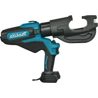
Line drawing of a Makita manual tool with handle and base (no text or symbols on the device itself)DTC303

Read before use.
WARNING: Please read and understand all of the instructions and safety information in this operator's guide and instructions. Use for unintended applications may lead to serious injury or death.
- Thank you for purchasing our Cordless Crimper.
- Please read these Operating Instructions thoroughly and carefully before attempting to use the equipment. After reading these operating instructions, store them in an easily accessible location.
Safety precautions
Be sure to observe the following
The following are the items that you should observe to prevent people from being harmed and property from being damaged.
WARNING: The user may be killed or seriously injured if this product is misused.
1) Work area safety
a) Keep work area clean and well lit. Cluttered or dark areas invite accidents.
b) Do not operate power tools in explosive atmospheres, such as in the presence of flammable liquids, gases or dust. Power tools create sparks which may ignite the dust or fumes.
c) Keep children and bystanders away while operating a power tool. Distractions can cause you to lose control.
2) Electrical safety
a) Power tool plugs must match the outlet. Never modify the plug in any way. Do not use any adapter plugs with earthed (grounded) power tools. Unmodified plugs and matching outlets will reduce risk of electric shock.
b) Avoid body contact with earthed or grounded surfaces, such as pipes, radiators, ranges and refrigerators. There is an increased risk of electric shock if your body is earthed or grounded.
c) Do not expose power tools to rain or wet conditions. Water entering a power tool will increase the risk of electric shock.
d) Do not abuse the cord. Never use the cord for carrying, pulling or unplugging the power tool. Keep cord away from heat, oil, sharp edges or moving parts. Damaged or entangled cords increase the risk of electric shock.
e) When operating a power tool outdoors, use an extension cord suitable for outdoor use. Use of a cord suitable for outdoor use reduces the risk of electric shock.
f) If operating a power tool in a damp location is unavoidable, use a residual current device (RCD) protected supply. Use of an RCD reduces the risk of electric shock.
3) Personal safety
a) Stay alert, watch what you are doing and use common sense when operating a power tool.
Do not use a power tool while you are tired or under the influence of drugs, alcohol or medication. A moment of inattention while operating power tools may result in serious personal injury.
b) Use personal protective equipment. Always wear eye protection. Protective equipment such as dust mask, non-skid safety shoes, hard hat, or hearing protection used for appropriate conditions will reduce personal injuries.
c) Prevent unintentional starting. Ensure the switch is in the off-position before connecting to power source and/or battery pack, picking up or carrying the tool. Carrying power tools with your finger on the switch or energizing power tools that have the switch on invites accidents.
d) Remove any adjusting key or wrench before turning the power tool on. A wrench or a key left attached to a rotating part of the power tool may result in personal injury.
e) Do not overreach. Keep proper footing and balance at all times. This enables better control of the power tool in unexpected situations.
f) Dress properly. Do not wear loose clothing or jewelry. Keep your hair, clothing and gloves away from moving parts. Loose clothes, jewelry or long hair can be caught in moving parts.
g) If devices are provided for the connection of dust extraction and collection facilities, ensure these are connected and properly used. Use of dust collection can reduce dust-related hazards.
h) Do not let familiarity gained from frequent use of tools allow you to become complacent and ignore tool safety principles. A careless action can cause severe injury within a fraction of a second.
4) Power tool use and care
a) Do not force the power tool. Use the correct power tool for your application. The correct power tool will do the job better and safer at the rate for which it was designed.
b) Do not use the power tool if the switch does not turn it on and off. Any power tool that cannot be controlled with the switch is dangerous and must be repaired.
c) Disconnect the plug from the power source and/or the battery pack from the power tool before making any adjustments, changing accessories, or storing power tools. Such preventive safety measures reduce the risk of starting the power tool accidentally.
d) Store idle power tools out of the reach of children and do not allow persons unfamiliar with the power tool or these instructions to operate the power tool. Power tools are dangerous in the hands of untrained users.
e) Maintain power tools and accessories. Check for misalignment or binding of moving parts, breakage of parts and any other condition that may affect the power tool's operation. If damaged, have the power tool repaired before use. Many accidents are caused by poorly maintained power tools.
f) Keep cutting tools sharp and clean. Properly maintained cutting tools with sharp cutting edges are less likely to bind and are easier to control.
g) Use the power tool, accessories and tool bits etc. in accordance with these instructions, taking into account the working conditions and the working conditions and the work to be performed.
Use of the power tool for operations different from those intended could result in a hazardous situations.
h) Keep handles and grasping surfaces dry, clean and free from oil and grease. Slippery handles and grasping surfaces do not allow for safe handling and control of the tool in unexpected situations.
5) Battery tool use and care
a) Recharge only with the charger specified by the manufacturer. A charger that is suitable for one type of battery pack may create a risk of fire when used with another battery pack.
b) Use power tools only with specifically designated battery packs. Use of any other battery packs may create a risk of injury and fire.
c) When battery pack is not in use, keep it away from other metal objects, like paper clips, coins, keys, nails, screws or other small metal objects, that can make a connection from one terminal to another. Shorting the battery terminals together may cause burns or a fire.
d) Under abusive conditions, liquid may be ejected from the battery; avoid contact. If contact accidentally occurs, flush with water. If liquid contacts eyes, additionally seek medical help. Liquid ejected from the battery may cause irritation or burns.
e) Do not use a battery pack or tool that is damaged or modified. Damaged or modified batteries may exhibit unpredictable behavior resulting in fire, explosion or risk of injury.
f) Do not expose a battery pack or tool to fire or excessive temperature. Exposure to fire or temperature above 130 °C may cause explosion.
g) Follow all charging instructions and do not charge the battery pack or tool outside the temperature range specified in the instructions. Charging improperly or at temperatures outside the specified range may damage the battery and increase the risk of fire.
6) Service
a) Have your power tool serviced by a qualified repair person using only identical replacement parts. This will ensure that the safety of the power tool is maintained.
b) Never service damaged battery packs. Service of battery packs should only be performed by the manufacturer or authorized service providers. Hold the power tool by insulated gripping surfaces, when performing an operation where the fastener may contact hidden wiring. Fasteners contacting a "live" wire may make exposed metal parts of the power tool "live" and could give the operator an electric shock.
Precautions in using cordless crimper
- When using this tool, follow the instructions as shown below:
Precautions for the tool
- Never operate the tool while the head is pointing in the direction of bystanders.
- When the tool has been stored for extended period at the temperature of 0^ C or less, leave it at a temperature of 10^ C to 15^ C for approximately 60 minutes. This is to ensure the smooth flow of hydraulic oil and also correct operation of the tool.
- Do not drop the tool or expose it to sudden shocks. This tool contains many small components and precision parts. The tool will not operate correctly if exposed to sudden shocks.
- Do not expose the tool to water, oil or solvents.
- Never operate the tool without dies and a connector in place.
• Always point the tool away from other people. - Do not drop the tool. Dropping the tool may damage the hydraulic circuit and result in the tool not functioning correctly.
- Keep the head and ram clean and free of debris. Solvents can be used to clean the head, but should not be used on the plastic body. Use soap and water to clean the body.
Precautions in using the battery pack
- Never short-circuit the terminals.
- Keep the battery pack away from water, oil or organic solvents.
- Do not disassemble or modify the battery pack.
- If the battery pack is disposed of, do not subject it to flames or dispose of it as general waste. (We promote recycling.) (see page 9)
- Do not throw or drop the battery pack.
- Do not leave the battery pack in a place where the temperature is 40^ or higher for a long time.
- Do not short-circuit the battery by placing dirt or dust on the terminal, as this will lead to malfunction. If the terminal is corroded, do not use the battery pack.
- A protective function that stops the output is equipped to prolong the life of the battery pack. The motor may stop when the remaining battery level is low even while the operation switch is pressed during the use of this tool. However, this phenomenon is caused not by malfunction but by the protective function. In such a case, immediately charge the battery.
Precautions for the battery charger
- This battery charger has an indicator lamp (multi-colored LED) to show the battery charging state.
- Do not short-circuit the charger by placing dirt or dust into the insertion slot, as this will lead to malfunction. If the metal terminal is corroded, do not use the battery charger.
Symbols
Only for EU countries
Due to the presence of hazardous components in the equipment, waste electrical and electronic equipment, accumulators and batteries may have a negative impact on the environment and human health.
Do not dispose of electrical and electronic appliances or batteries with household waste!
In accordance with the European Directive on waste electrical and electronic equipment and on accumulators and batteries and waste accumulators and batteries, as well as their adaptation to national law, waste electrical equipment, batteries and accumulators should be stored separately and delivered to a separate collection point for municipal waste, operating in accordance with regulations on environmental protection. This is indicated by the symbol of a crossed-out wheeled bin placed on the equipment.

⚠ WARNING: To reduce the risk of arc flash, electric shock and property damage, work on deenergized lines when possible. The tool is not insulated. Should work on energized lines be required, ensure that all proper precautions, including those contained in NFPA 70E, have been taken first.
Noise
The typical A-weighted noise level determined according to EN62841-1:
Sound Pressure level (K=3 dB(A)): 61.9 dB(A)
Sound Power level (K=3 dB(A)): 73.1 dB(A)
NOTE: The declared noise emission value(s) has been measured in accordance with a standard test method and may be used for comparing one tool with another.
NOTE: The declared noise emission value(s) may also be used in a preliminary assessment of exposure.
WARNING:
- Wear ear protection.
- The noise emission during actual use of the power tool can differ from the declared value(s) depending on the ways in which the tool is used, especially what kind of workpiece is processed.
- Be sure to identify safety measures to protect the operator that are based on an estimation of exposure in the actual conditions of use (taking into account of all parts of the operating cycle such as the times when the tool is switched off and when it is running idle in addition to the trigger time).
Vibration
The vibration total value (tri-axial vector sum) determined according to EN62841-1:
Handle: 0.4 m/s ^2
Uncertainty (K): 1.5 m/s ^4
NOTE: The declared vibration total value(s) has been measured in accordance with a standard test method and may be used for comparing one tool with another.
NOTE: The declared vibration total value(s) may also be used in a preliminary assessment of exposure.
WARNING:
- The vibration emission during actual use of the power tool can differ from the declared value(s) depending on the ways in which the tool is used, especially what kind of workpiece is processed.
- Be sure to identify safety measures to protect the operator that are based on an estimation of exposure in the actual conditions of use (taking into account of all parts of the operating cycle such as the times when the tool is switched off and when it is running idle in addition to the trigger time).
Applicable battery cartridge and charger
Battery cartridge BL1815N / BL1820B / BL1830B / BL1840B / BL1850B / BL1860B
Charger DC18RC / DC18RD / DC18RE / DC18SD / DC18SE / DC18SF /
DC18SH / DC18WC
- Some of the battery cartridges and chargers listed above may not be available depending on your region of residence.
- To charge the battery, please read the instruction manual for the battery charger.
⚠ WARNING: Only use the battery cartridges and chargers listed above. Use of any other battery cartridges and chargers may cause injury and/or fire.
Important safety instructions for battery cartridge
- Before using battery cartridge, read all instructions and cautionary markings on (1) battery charger, (2) battery, and (3) product using battery.
- Do not disassemble or tamper with the battery cartridge. It may result in a fire, excessive heat, or explosion.
- If operating time has become excessively shorter, stop operating immediately. It may result in a risk of overheating, possible burns and even an explosion.
-
If electrolyte gets into your eyes, rinse them out with clear water and seek medical attention right away. It may result in loss of your eyesight.
-
Do not short the battery cartridge:
(1) Do not touch the terminals with any conductive material.
(2) Avoid storing the battery cartridge in a container with other metal objects such as nails, coins, etc.
(3) Do not expose the battery cartridge to water or rain.
A battery short can cause a large current flow, overheating, possible burns and even a breakdown.
-
Do not store or use the tool and battery cartridge in locations where the temperature may reach or exceed 50^ C ( 122^ F).
-
Do not incinerate the battery cartridge even if it is severely damaged or is completely worn out. The battery cartridge can explode in a fire.
-
Do not nail, cut, crush, throw, or drop the battery cartridge, or allow a hard object to hit the battery cartridge. Such conduct may result in a fire, excessive heat, or explosion.
-
Do not use a damaged battery.
-
The contained lithium-ion batteries are subject to the Dangerous Goods Legislation requirements.
For commercial transport e.g. by third parties, forwarding agents, special requirements on packaging and labeling must be observed.
For preparation of the item being shipped, consulting an expert regarding hazardous material is required. Please also observe possibly more detailed national regulations.
Tape over or cover open contacts and pack up the battery in such a manner that it cannot move around in the packaging.
-
When disposing of the battery cartridge, remove it from the tool and dispose of it in a safe place. Follow your local regulations relating to disposal of batteries.
-
Use the batteries only with products specified by Makita. Installing the batteries to non-compliant products may result in a fire, excessive heat, explosion, or leak of electrolyte.
-
If the tool is not used for a long period of time, the battery must be removed from the tool.
-
During and after use, the battery cartridge may take on heat, which can cause burns or low-temperature burns. Pay attention to the handling of hot battery cartridges.
-
Do not touch the terminal of the tool immediately after use, as it may get hot enough to cause burns.
-
Do not allow chips, dust or soil stuck into the terminals, holes and grooves of the battery cartridge. It may cause heating, catching fire, burst or malfunction of the tool or battery cartridge, resulting in burns or personal injury.
-
Unless the tool supports use near high-voltage electrical power lines, do not use the battery cartridge near high-voltage electrical power lines. It may result in a malfunction or breakdown of the tool or battery cartridge.
-
Keep the battery away from children.
SAVE THESE INSTRUCTIONS.
CAUTION:
- Only use genuine Makita batteries.
Use of non-genuine Makita batteries, or batteries that have been altered, may result in the battery bursting, causing a fire, personal injury and damage. It will also void the Makita warranty for the Makita tool and charger.
Tips for maintaining maximum battery life
- Charge the battery cartridge before it is completely discharged. Always stop tool operation and charge the battery cartridge when you notice less tool power.
- Never recharge a fully charged battery cartridge. Overcharging shortens the battery service life.
- Charge the battery cartridge at room temperature at 10^ C– 40^ C ( 50^ F– 104^ F). Let a hot battery cartridge cool down before charging it.
- When not using the battery cartridge, remove it from the tool or the charger.
- Charge the battery cartridge if you do not use it for a long period (more than six months).
Parts and standard accessories
DTC303
Cordless Crimper
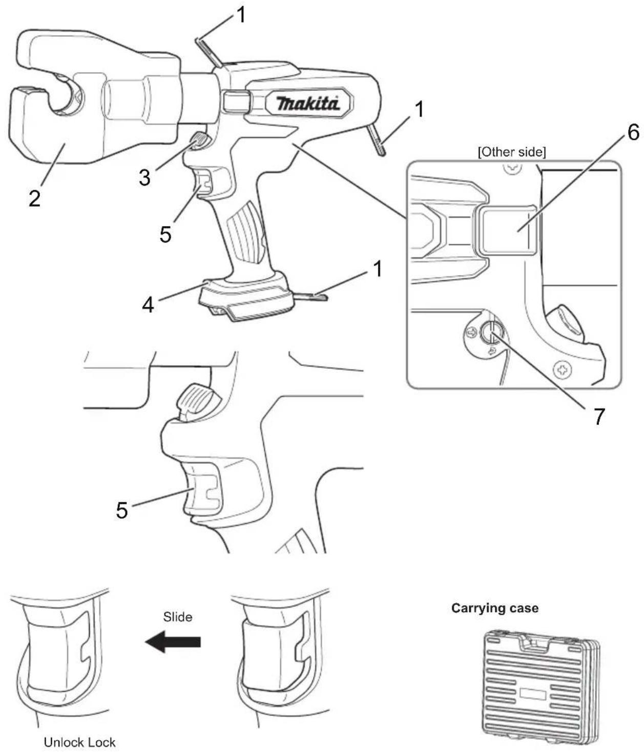
| 1 Strap 5 Trigger with lock | ||
| 2 Head 6 For service (Do not remove the cover.) | ||
| 3 Release knob 7 Auto retract function (see page 10.) | ||
| 4 LED work light |
Battery
Battery
- At the time of purchase, the battery protection function may be activated due to the battery not being sufficiently charged. (Please be careful because this product may start operating if you operate the switch.) Correctly charge the battery with the rapid charger before use.
- Attach the battery cover when not using the product. It will help protect the battery from water and dust.
- When not using the product for a long period, store it with the battery removed.
To increase the life of the battery
- When you sense that the force of the tool has become weak, stop use and charge the battery.
- Do not recharge a battery that is fully charged.
- Charge the battery in an ambient temperature range of 10^ to 40^ .
- When the battery has become hot such as immediately after use, we recommend inserting it into the charger to cool and charge it.
- When a lithium-ion battery will not be used for a long period of time (at least 6 months), we recommend charging and then storing it.
Battery collection
- Used batteries are collected for recycling. Please take the battery to the store where you purchased the product or a Makita sales office.

Li-ion
Recycle the lithium-ion battery
How to attach and detach the battery
WARNING:
Insert the battery into the product properly. If the red part at the top of the button is visible, the battery is not fully locked into place. Firmly insert the battery until all of the red part cannot be seen.
- If the battery is not inserted sufficiently, it may detach and cause an accident.
- To detach the battery from this product, A. hold down the button on the battery front and B. slide the battery to remove it.
- When attaching the battery, align the battery with the grooves in the product and then insert it all the way by performing the procedure in reverse. If the red part at the top of the button is visible at this time, the battery is not fully locked into place. Insert the battery properly all the way until all of the red part cannot be seen.
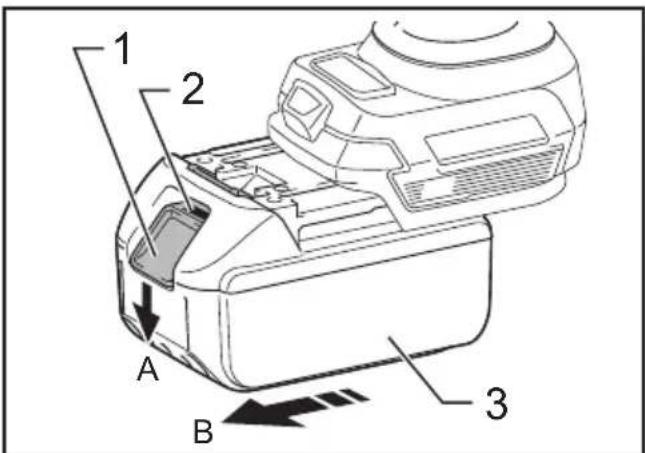
▶ 1. Button 2. Red part 3. Battery
Indicating the remaining battery capacity
Only for battery cartridges with an indicator
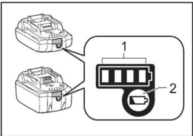
▶ 1. Indicator lamps 2. Check button
Press the check button on the battery cartridge to indicate the remaining battery capacity. The indicator lamps light up for a few seconds.
| Indicator lamps Remaining | capacity | ||
| Lighted Off | Blinking | ||
| 75% to 100% | |||
| 50% to 75% | |||
| 25% to 50% | |||
| 0% to 25% | |||
| Charge the battery. | |||
| The battery may have malfunctioned. | |||
NOTE: Depending on the conditions of use and the ambient temperature, the indication may differ slightly from the actual capacity. NOTE: The first (far left) indicator lamp will blink when the battery protection system works.
Applicable compression range
| Applicable compression range | Opening between nibs: 32 mm |
Specifications
| Nominal output 60 kN | |
| Oil capacity 78 ml | |
| Electric motor DC motor | |
| Dimension (mm) D398 × H298 × W81 | |
| Weight 5.3–5.7 kg | |
The weight may differ depending on the attachment(s), including the battery cartridge. The lightest and heaviest combination are shown in the table.
How to use the tool
Attaching the battery pack
-
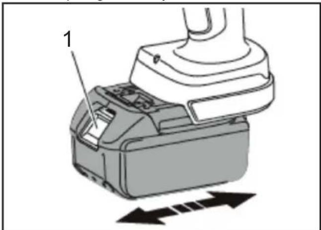
While pressing the latch, pull out the battery pack. To replace the battery pack, push the new pack firmly into place.
-
After sliding a battery pack on, check if it is securely in place by pulling it gently. Do not press the latch when pulling the battery.
natural_image
Diagram of a mechanical device with labeled component '1' and directional arrows indicating movement (no text or symbols beyond label)▶ 1. Latch
Select Auto retract / Manual
Auto retract is a function to automatically retract the ram to the original position after completing compression.
The Auto retract function is set to ON at shipment.
To set the function to manual, remove the cover and set the direction of the groove using a flat-head driver.
To set the function to ON again, change the direction of the groove to ⚙.
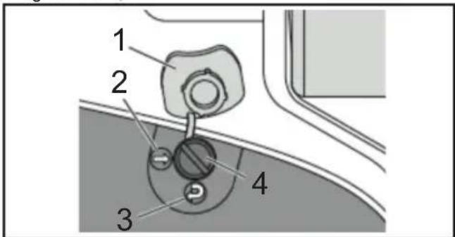
▶ 1. Cover 2. OFF 3. ON 4. Groove
Trigger & Release knob
The ram advances when the trigger is pulled.
Keep pulling the trigger until it reaches the set load.
Then, the ram automatically retracts to the lower end.
To stop the ram at the desired position, tap the trigger once. (Auto retract mode)
To retract the ram manually, press the release knob. The ram continues to retract while the release lever is pressed. (Manual and Auto retract mode) Pressing the operation switch operates the motor of the tool and raises the piston.
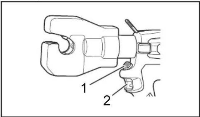
▶ 1. Release knob 2. Trigger
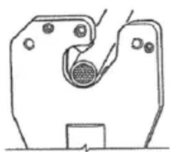
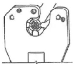
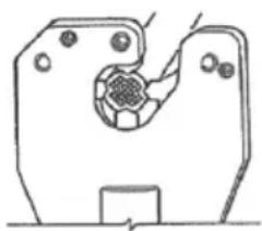
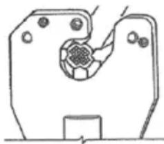
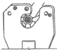
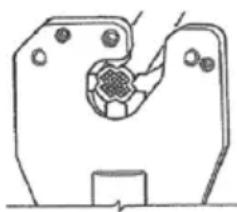
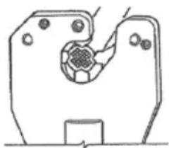
Crimping operations
- Retract the nibs by pressing the release knob.
- Insert the connector and center it between the nibs.
-
Activate the trigger and advance the nibs then, the connector is held between the nibs.
-
Insert the conductor into the connector.
-
Press the trigger until the compression is completed. A click will be heard when compression is completed.
-
Keep pressing the trigger. The ram automatically retracts to the lower end. (Auto retract mode)
-
Remove the conductor from the tool.
natural_image
Technical line drawing of a mechanical component with a central circular feature and mounting holes (no text or symbols)

WRONG RIGHT
natural_image
Pure mechanical component diagram without any text, numbers, or symbolsAttaching the Shoulder belt
Optional accessory
The shoulder belt can be attached to the hanging rings of the tool to carry the tool.
WARNING:
• Always remove the shoulder belt from the tool when working with the tool. Failure to do so may cause a loss of balance and result in an accident.
- Use only the shoulder belt designated for this tool. Make sure that the shoulder belt is securely attached to the tool when carrying the tool.
- When using the shoulder belt, carefully inspect the shoulder belt and the hanging rings for damage, cracks, or deformation. If there is any damage, stop using the shoulder belt and ask Makita Authorized Service Center for repair.
Maintenance/Inspection
- Daily maintenance is required to ensure that the tool is kept in good condition.
- Do not store the tool in a humid environment to maintain smooth movement of parts and to prevent rust.
- If the tool is damaged by normal operation at over 10,000 times, it is the end of its life.
Do not use the tool again even after replacement of the damaged part. -
When a resin part becomes dirty, wipe away with a soapy cloth.
-
When the battery pack is stored alone, be sure to put the accessory terminal cover on the terminal to prevent short circuit.
- The tool performance may deteriorate due to degradation of its parts or hydraulic oil.
Have your tool maintained every two years to use it to the end of its life (with charge). For further information, please contact an authorized service facility.
Declarations of Conformity
For European countries only
The Declarations of conformity are included in Annex A to this instruction manual.
Chargeur DC18RC/DC18RD/DC18RE/DC18SD/DC18SE/DC18SF/
DC18SH/DC18WC
Plage de compression applicable
natural_image
Diagram of a mechanical device with labeled component '1' and directional arrows indicating movement (no text or symbols beyond label)▶ 1. Loquet
natural_image
Pure mechanical component diagram without any text, numbers, or symbols

INCORRECT CORRECT
natural_image
Pure mechanical component diagram without any text, numbers, or symbolsMaintenance/Inspection
natural_image
Diagram of a mechanical device with a labeled component and directional arrows indicating movement (no text or symbols present)▶ 1. Klinke
natural_image
Pure mechanical component diagram without any text, numbers, or symbols

FALSCH RICHTIG

natural_image
Pure mechanical component diagram without any text, numbers, or symbolsCaricabatterie DC18RC/DC18RD/DC18RE/DC18SD/DC18SE/DC18SF/
DC18SH/DC18WC
natural_image
Diagram of a mechanical device with labeled component '1' and directional arrows indicating movement (no text or symbols beyond label)natural_image
Pure mechanical component diagram without any text, numbers, or symbols

ERRATO CORRETTO

natural_image
Pure mechanical component diagram without any text, numbers, or symbols▶ 1. Indicatielampjes 2. Controleknop
natural_image
Diagram of a mechanical device with a labeled component and directional arrows indicating movement (no text or symbols present)▶ 1. Ontgrendelknop
Selecteer Automatisch openen of Handmatig openen
▶ 1. Open-knop 2. Trekker
Krimpbediening
natural_image
Pure mechanical component diagram without any text, numbers, or symbols

FOUT JUIST

natural_image
Pure mechanical component diagram without any text, numbers, or symbolsnatural_image
Diagram of a mechanical device with a labeled component and directional arrows indicating movement (no text or symbols present)▶ 1. Seguro
natural_image
Pure mechanical component diagram without any text, numbers, or symbols

INCORRECTO CORRECTO
natural_image
Pure mechanical component diagram without any text, numbers, or symbols▶ 1. Indikatorlamper 2. Kontrolknap
natural_image
Diagram of a mechanical device with labeled component '1' and directional arrows indicating movement (no text or symbols beyond label)▶ 1. Lås
natural_image
Pure mechanical component diagram without any text, numbers, or symbols

FORKERT KORREKT
natural_image
Pure mechanical component diagram without any text, numbers, or symbolsLaddare DC18RC / DC18RD / DC18RE / DC18SD / DC18SE / DC18SF /
DC18SH / DC18WC
▶ 1. Indikatorlampor 2. Kontrollknapp
natural_image
Diagram of a mechanical device with labeled component '1' and directional arrows indicating movement (no text or symbols beyond label)▶ 1. Spärr
▶ 1. Frigöringsknapp 2. Avtryckare
Krimpning
natural_image
Pure mechanical component diagram without any text, numbers, or symbols

FEL RÄTT

natural_image
Pure mechanical component diagram without any text, numbers, or symbolsFästa axelremmen
Valfritt tillbehör
▶ 1. Indikatorlamper 2. Kontrollknapp
natural_image
Diagram of a mechanical device with labeled component '1' and directional arrows indicating movement (no text or symbols beyond label)▶ 1. Klemme
natural_image
Pure mechanical component diagram without any text, numbers, or symbols

GALT RIKTIG

natural_image
Pure mechanical component diagram without any text, numbers, or symbolsFeste skulderremmen
Valgfritt tilbehør
Akku BL1815N/BL1820B/BL1830B/BL1840B/BL1850B/BL1860B
Laturi DC18RC/DC18RD/DC18RE/DC18SD/DC18SE/DC18SF/
DC18SH/DC18WC
natural_image
Diagram of a mechanical device with labeled component '1' and directional arrows indicating movement (no text or symbols beyond label)▶ 1. Salpa
natural_image
Pure mechanical component diagram without any text, numbers, or symbols

VÄÄRIN OIKEIN

natural_image
Pure mechanical component diagram without any text, numbers, or symbols▶ 1. Poga 2. Sarkanā dala 3. Akumulators
▶ 1. Indikatora lampiņas 2. Pārbaudes poga
natural_image
Diagram of a mechanical device with labeled component '1' and directional arrows indicating movement (no text or symbols beyond label)▶ 1. Fiksators
▶ 1. Pärsegs
2. IZSLĚGTS
3. IESLÊGTS
4. Grope
▶ 1. Atbrīvošanas grozámpoga
2. Sprüds
natural_image
Pure mechanical component diagram without any text, numbers, or symbols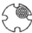

APLAMI PAREIZI
natural_image
Pure mechanical component diagram without any text, numbers, or symbolsnatural_image
Diagram of a mechanical device with labeled component '1' and directional arrows indicating movement (no text or symbols beyond label)▶ 1. Skląstis
Automatinio / rankinio jtraukimo pasirinkimas
natural_image
Pure mechanical component diagram without any text, numbers, or symbols

NETAISYKLINGAI TAISYKLINGAI
natural_image
Pure mechanical component diagram without any text, numbers, or symbolsHOIDKE NEED JUHISED ALLES.
ETTEVAATUST!
natural_image
Diagram of a mechanical device with labeled component '1' and directional arrows indicating movement (no text or symbols beyond label)▶ 1. Riiv
natural_image
Pure mechanical component diagram without any text, numbers, or symbols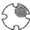

VALE ŌIGE

natural_image
Pure mechanical component diagram without any text, numbers, or symbolsÕlarihma kinnitamine
Valikuline tarvik
聲壓位準 (K=3 dB (A)): 61.9 dB (A)
聲功率位準 (K=3 dB (A)): 73.1 dB (A)
- 指示燈 2. 檢查按鈕
natural_image
Diagram of a mechanical device with labeled component '1' and directional arrows indicating movement (no text or symbols beyond label)- 門鎖
選擇自動縮回/手動
▶ 1. 釋放旋鈕 2. 扳柄
壓接操作
natural_image
Pure mechanical component diagram without any text, numbers, or symbols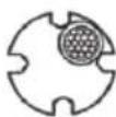
錯誤