
FHER6117CTNX3 - Oven BERTAZZONI - Free user manual and instructions
Find the device manual for free FHER6117CTNX3 BERTAZZONI in PDF.


User questions about FHER6117CTNX3 BERTAZZONI
0 question about this device. Answer the ones you know or ask your own.
Ask a new question about this device
Download the instructions for your Oven in PDF format for free! Find your manual FHER6117CTNX3 - BERTAZZONI and take your electronic device back in hand. On this page are published all the documents necessary for the use of your device. FHER6117CTNX3 by BERTAZZONI.
USER MANUAL FHER6117CTNX3 BERTAZZONI
text_image
BERTAZZO ITALIA| IT | MANUALE D'INSTALLAZIONEMANUALE D'USO E MANUTENZIONEFORNI A VAPORE AD INCASSO | 3 |
| EN | INSTALLATION MANUALUSER AND MAINTENANCE MANUALBUILT-IN STEAM OVENS | 41 |
| FR | MANUEL D'INSTALLATIONMANUEL D'UTILISATION ET D'ENTRETIENFOURS À VAPEUR ENCASTRÉS | 79 |
DALLA SCRIVANIA DEL PRESIDENTE
Gentile Cliente,
FHER6117CTAG3
FHER6117CTAX3
FHER6117CTNX3
- FMOD6117CTB3
- FMOD6117CTG3
- FMOD6117CTM3
- FMOD6117CTN3
- FMOD6117CTS3
- FMOD6117CTX3
- FMOD6117CTB1
- FPRO6117CTN3
- FPRO6117CTX3
VENTOLA CON GRILL 24
ASSISTENTE 24
MODALITÀ DI COTTURA SPECIALI 24
DISIDRATAZIONE 24
SCONGELAMENTO 24
RISCALDAMENTO 24
LIEVITAZIONE 24
SABBATH 24
ECO 24
SOLO VAPORE 24
FRITTURA AD ARIA 24
PULIZIA 25
PIROLISI 25
ECO PIROLISI 25
HYDROCLEAN 25
HYDROCLEAN (SOLO FORNO A UNDICI FUNZIONI) 25
VAPORE 25
COTTURA CON L'AUSILIO DEL VAPORE 25
LIVELLI VAPORE 25
COTTURA VAPORE 25
POMPA 25
SERBATOIO ACQUA 26
ACCESSORI VAPORE 26
text_image
Technical diagram of a microwave oven with labeled components and a control panel on the leftFig. 1
text_image
1 P Produzione / Manufacturer / Produceur / Producenti / Fabricante: BZL 2024 L'AZIONI S.p.a - Via Palazzina 8, 42016 Guastalla (RE) - ITAL MODEL CODE / COD COMM / BESTELNUMMER CODE COMM / CODIGO COMERCIAL / NADDELSKODE FACTORY CODE / MODELLO / MODEL/MODELE/MODELO MATR 220 - 240 Vac 50/60 Hz 2100 W 2 3 2 3Fig. 2
text_image
13 A = 21 MOD A = 23 HER A = 24 PRO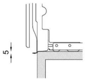
text_image
5Fig. 3
natural_image
Simple line drawing of a 3D rectangular frame with two downward arrows inside, no text or symbols present.Fig. 4
natural_image
Technical line drawing of a mechanical assembly with a screwdriver inserted into a housing (no text or symbols)Fig. 9
natural_image
Technical line drawing of a mechanical assembly with multiple parallel plates and mounting holes (no text or symbols)Fig. 10
natural_image
Technical line drawing of a ladder assembly with screwdriver and bracket (no text or symbols)Fig. 11
natural_image
Technical line drawing of a cabinet or storage unit with curved metal frame and mounting holes (no text or symbols)Fig. 12
natural_image
Simple diagram with a rectangle centered on two horizontal lines, labeled '1' at the bottom (no text or symbols within the diagram itself)Fig. 15
Fig. 14 1) Display con touch control
natural_image
Diagram of a refrigerator interior showing door, drawer, and drawer with directional arrows indicating movement (no text or symbols)Fig. 17
natural_image
Technical diagram of a mechanical assembly with two views: top shows a rectangular plate and bottom shows a multi-compartment housing (no text or symbols)Fig. 18
natural_image
Technical line drawing of a mechanical assembly with an arrow indicating rotation (no text or symbols present)Fig. 19
TABELLA INDICATIVA PER LA COTTURA
natural_image
Technical line drawing of a door frame with a horizontal panel and two arrows indicating assembly or movement (no text or symbols)Fig. 23
natural_image
Technical line drawing of a door frame with horizontal metal racks and directional arrows indicating movement (no text or symbols)Fig. 24
natural_image
Technical diagram of a mechanical assembly with a lever and guide mechanism (no text or symbols)PULIZIA DELL'APPARECCHIO
natural_image
Technical line drawing of a door frame with horizontal insulation and two arrows indicating direction (no text or symbols)Fig. 25
natural_image
Technical line drawing of a mechanical component with two upward arrows indicating motion or assembly (no text or symbols present)Fig. 26
natural_image
Technical line drawing showing two views of a mechanical component mounted on a panel (no text or symbols)SOSTITUZIONE GUARNIZIONI SERBATOIO
natural_image
Technical line drawing of a mechanical component with an inset showing a close-up view of a housing or mounting bracket (no text or symbols present)Fig. 28
Fig. 27
natural_image
Technical line drawing of a mechanical assembly with a curved component and directional arrow (no text or symbols)Fig. 30
natural_image
Technical line drawing of a mechanical component with arrows indicating motion or assembly (no text or symbols)Fig. 31
natural_image
Technical line drawing of a door frame with mounting brackets and a dashed circle highlighting a specific area (no text or symbols)Fig. 29
natural_image
Technical line drawing of a door frame with arrows indicating direction (no text or symbols)Fig. 32
natural_image
Technical line drawing of a mechanical assembly with an upward arrow indicating motion or force (no text or symbols present)Fig. 33
natural_image
Technical line drawing of a mechanical assembly with an upward arrow indicating motion (no text or symbols present)Fig. 34
L'APPARECCHIO NON FUNZIONA.
Dear new owner of a Bertazzoni appliance,
I want to thank you for choosing one of our beautiful products for your home.
My family started manufacturing kitchen appliances in Italy in 1882, building a reputation for quality of engineering and passion for good food.
Today, our products stand out because of their unique blend of authentic Italian design and superior appliance technology. It is our mission to make products that function perfectly and bring joy to their owners.
By making beautiful products we respond to our customers' flair for good design. By making them versatile and easy-to-use, cooking with Bertazzoni becomes a real pleasure.
This manual will help you learn to use and care for your Bertazzoni appliance in the safest and most effective way, so that it can give you the highest satisfaction for years to come.
Enjoy!
Paolo Bertazzoni
President
Polo Sectorzou
VALIDITY OF USER MANUAL
This user manual is valid for the following product codes:
FHER6117CTAG3
FHER6117CTAX3
FHER6117CTNX3
- FMOD6117CTB3
- FMOD6117CTG3
- FMOD6117CTM3
- FMOD6117CTN3
- FMOD6117CTS3
- FMOD6117CTX3
- FMOD6117CTB1
FPRO6117CTN3
- FPRO6117CTX3
GENERAL INFORMATION 47
READING THE MANUAL 47
INTRODUCTION AND SAFETY 47
GENERAL SAFETY INFORMATION 48
MANUFACTURER LIABILITY 49
ENVIRONMENTAL PROTECTION 49
GENERAL SAFETY INSTRUCTIONS 50
WARNINGS FOR USE 51
APPLIANCE WARNINGS 52
INSTALLATION 53
TECHNICAL MANUAL FOR THE INSTALLER 53
INSTALLING THE OVEN IN THE UNIT 53
IMPORTANT INFORMATION 54
INSTALLATION UNDERNEATH A BUILT-IN HOB 54
INSTALLING THE OVEN IN A TALL APPLIANCE HOUSING 55
FIXING THE OVEN 56
ELECTRICAL CONNECTION 57
REPLACING COMPONENTS 57
USE 58
CONTROL PANEL 58
TWO-KNOB OVEN CONTROLS 58
FULL-TOUCH OVEN CONTROLS 58
OVEN FUNCTIONS 59
FIRST USE 59
FIRST SWITCH-ON 59
PRELIMINARY OPERATIONS 60
RACK POSITIONING 60
COOLING 60
PREHEATING 60
OVEN LIGHT 60
WATER HARDNESS 60
USING TWO-KNOB OVENS 60
PROGRAMMING THE PROBE 69
ASSISTANT 70
CLEANING THE APPLIANCE 72
CLEANING ENAMELLED OR PAINTED PARTS: 72
CLEANING STAINLESS-STEEL PARTS: 72
CLEANING THE DOOR GLAZING 72
CLEANING THE OVEN RACKS 72
CLEANING HANDLES 72
SEAL 72
REMOVING THE SIDE GUIDES 72
REPLACING THE OVEN LIGHT 73
OVEN SIDE LIGHT (WHERE FITTED) 73
REPLACING RESERVOIR SEAL 73
CLEANING THE INTERNAL DOOR GLASS 74
TROUBLESHOOTING 76
THE OVEN DOES NOT WORK 76
THE OVEN DOES NOT HEAT UP 76
THE KNOB WILL NOT STAY IN PLACE. 76
THE CONTROLS ARE VERY HOT 76
FOOD IS OVERCOOKED. 76
THE RESULTS OF CLEANING ARE NOT IDEAL 76
THE OVEN INDICATES THAT IT IS OUT OF WATER 76
WATER COMING OUT OF THE TRAY. 76
THE DESCALING PROCEDURE IS INTERRUPTED BEFORE IT FINISHES. 76
THERE IS DIRTY WATER ON THE BASE OF THE OVEN AFTER THE DESCALING PROCEDURE . . . .
WARRANTY AND SERVICE 77
READING THE MANUAL
These instructions are suitable for different types of appliances, so they may contain descriptions of functions which your appliance may not contain or support.
The images and illustrations in this document refer to various models and may differ slightly from the product purchased.
The manufacturer does not accept any responsibility for personal injury or damage to property arising from incorrect installation or misuse of the appliance.
The manufacturer reserves the right to modify the various models as required to comply with the technical regulations in force.
The manufacturer shall also not be held liable for any imprecisions due to printing or transcription errors in this booklet.
These instructions are valid only for the countries whose identifying symbols are included on the cover of this manual and on the appliance label.
THIS APPLIANCE IS DESIGNED FOR NON-PROFESSIONAL, DOMESTIC USE.
This user manual is an integral part of the appliance and must therefore be kept in its entirety in a place accessible to the user for the entire lifetime of the appliance.
In the event of complaints, please contact the customer service.
Read this manual before using the appliance.
INTRODUCTION AND SAFETY
Read the instructions provided in this manual carefully before installing and/or using the appliance.
This will help you to get to know your new device.
Keep this document to hand so that you consult it at any moment, and hand it on to any subsequent owners.
Read the safety messages provided in the introduction to this manual and give due consideration to the safety notes such as: "Attention", "Warning" and "Danger" which appear in the text.

DANGER
This symbol indicates a situation that is a danger to you and others. Read it carefully and make sure that you have perfectly understood the causes of potential dangerous or fatal accidents.

WARNING
This symbol indicates safety information. Read it carefully and make sure that you have perfectly understood the causes of potential dangerous accidents.

CAUTION
This symbol indicates a procedure which could put the appliance's structure or components at risk. Take particular care over these procedures.

NOTE
This symbol indicates useful advice and draws your attention to correct procedures and practices. Complying with the instructions marked with this symbol will avoid problems for you.
The symbol highlights methods or procedures for correct use of the appliance.
GENERAL SAFETY INFORMATION
This appliance complies with European directive 2012/19/EU (RoHS).
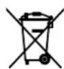
This appliance is tagged in accordance with European directive 2012/19/EC regarding waste electrical and electronic equipment (WEEE).
This directive contains the regulations governing the collection and recycling of decommissioned appliances throughout the European Union.

The symbol of a waste bin with a cross over it which appears on the product indicates that Waste Electrical and Electronic Equipment (WEEE) must not be thrown away with ordinary urban waste but must be disposed of separately, so it can undergo special processing to enable its reuse or specific treatment for safe removal and disposal of any substances harmful to the environment and extraction of raw materials which can be recycled.
Therefore, WEEE must be delivered to Recycling Centres run by Municipal Authorities or Waste Management Companies. What's more, when a new appliance is purchased WEEE can be consigned to the retailer, who is obliged to take it back free of charge ("1:1" take-back). "Very small" WEEE (with no dimension exceeding 25 cm) can be consigned to retailers free of charge even when no purchase is made ("0:1" take-back - which however is only compulsory for stores with sales area of over 400 m2).

DANGER
This appliance is not intended for use by people, including children, with reduced mental or motor capabilities, or who do not have experience in or knowledge of the product's operation. These persons may only use the appliance under the supervision of a person responsible for their safety and with suitable instruction in use of the appliance.

DANGER
If the surface of the induction hob is cracked, switch the appliance off to avoid the risk of electric shocks.

DANGER
Fire hazard: do not leave inflammable objects on cooking surfaces.

DANGER
Automatic cooking on the hob with fat or oil may be hazardous and may cause fires. If a fire breaks out, do not attempt to put it out with water. Switch the appliance off and cover the flames with a lid or a fire blanket.

DANGER
This appliance can be used by children over 8 years of age and persons with reduced physical, sensory or mental capabilities, or without the necessary of experience and knowledge, provided they are supervised or have received instruction concerning safe use of the appliance and an understanding of the hazards involved. Children must not play with the appliance. Cleaning and user maintenance must not be carried out by unsupervised children.

WARNING
The appliance and its accessible parts become very hot during use. Do not touch the heating elements. Children under 16 years of age must be kept away from the appliance unless constantly supervised.
Do not touch the heating elements of the hob and/or inside the oven.

WARNING
Accessible parts may become hot during use. Children must be kept well away.

WARNING
Make sure that the appliance is disconnected from the electrical mains before replacing the lamp to avoid possible electric shocks.

WARNING
The cooker must not be installed on a stand.

WARNING
Do not use steam cleaners to clean the appliance.

CAUTION
Do not use an external timer or other remote control systems to operate the appliance.
MANUFACTURER LIABILITY
The manufacturer shall bear no liability for property damage or personal injury due to:
• Use of the appliance other than that specified.
- Failure to comply with the instructions in the user manual.
- Tampering with/ unauthorized modifications to any part of the appliance.
• The use of non-genuine spare parts.
- This appliance is intended for cooking food in the home environment. Any other use shall constitute misuse.
- The appliance is not designed to operate with external timers or with remote-control systems.

CAUTION
Application of the marking CE on this product is a declaration, under the manufacturer's full responsibility, that the product complies with all European health, safety and environmental requirements laid out in the legislation covering this product type.
ENVIRONMENTAL PROTECTION
Please think of the environment when disposing of the packaging.

This appliance is tagged in accordance with European directive 2012/19/EU regarding waste electrical and electronic equipment (WEEE).
This directive contains the regulations governing the collection and recycling of decommissioned appliances throughout the European Union.
The packaging of this appliance is composed of the elements strictly necessary to ensure sufficient protection during transport. The packaging materials are completely recyclable, thus reducing their environmental impact. Please help to protect the environment by taking the following tips into consideration:
- Sort the packaging materials for recycling.
- Render the old appliance unusable before taking it to the collection facility. Ask the competent local authorities for details of the nearest recycling center you can take the old appliance to.
- Do not dispose of used oil down the drain. Keep it in a closed container and take it to a recycling center; if this is not possible, dispose of it in mixed waste (in this manner it will be disposed of at a monitored facility – although this is not the best solution, it at least prevents contamination of the sewage/water systems).
PLASTIC PACKAGING
Danger of suffocation
- Do not leave the packaging or any part thereof unattended.
- Do not let children play with the plastic bags.
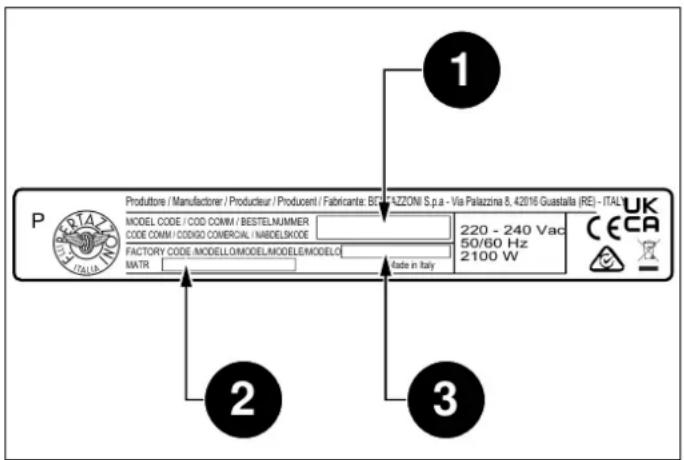
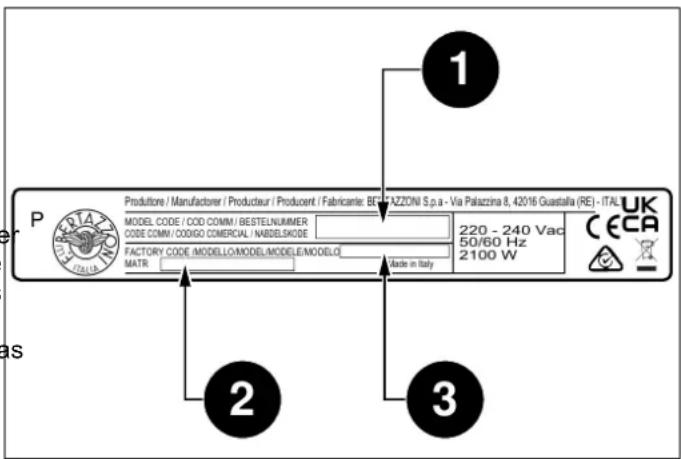
APPLIANCE IDENTIFICATION
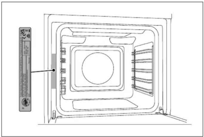
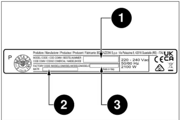
The appliance data plate is located on the side of the front. This appliance and its accessible parts become very hot of the oven, and must not be removed at any time. A copy during use.
is provided in this manual for reference.
text_image
Technical diagram of an oven with labeled components and a control panel on the leftFig. 1
text_image
1 P Produzione / Manufacturer / Producler / Producent / Fabricante: BZF/FAZZONI S.p.a - Via Palazzina 8, 42016 Guastalla (RE) - ITAL MODEL CODE / COD COMM / BESTELNUMMER CODE COMM / CODIGO COMERCIAL / MABELSKODE FACTORY CODE /MODELO/MODEL/MODELE/MODELO MATR 220 - 240 Vac 50/60 Hz 2100 W CECA UK 3 2 Made in ItalyFig. 2
The dataplate contains the following information:
You are advised to make a note of the appliance's data and serial numbers so they are immediately available if required.

NOTE
State the information provided on the dataplate to improve the efficiency of the after-sales and parts services.
GENERAL SAFETY INSTRUCTIONS
- Do not operate the appliance with wet hands or when it is in contact with water.
- Do not touch heating elements during use.
- Keep children under 8 years of age at a safe distance unless they are constantly supervised.
• Children must not play with the appliance.
- This appliance may be used by children from 8 years of age and people with reduced physical, sensory or mental capabilities, or lack of experience and knowledge, provided they are supervised or instructed by adults responsible for their safety.
- Keep children and animals away from the appliance while it is running or cooling down. Accessible parts become red hot during use.
- Switch off the appliance after use.
- Cleaning and maintenance must not be carried out by children.
- Ensure that hot surfaces are allowed to cool before proceeding to clean the appliance.
- Have installation and servicing carried out by qualified personnel in compliance with applicable standards and legislation. Do not try to repair the appliance yourself or without the assistance of a qualified technician.
- Do not modify this appliance.
- Do not insert anything in the slots.
- Do not obstruct ventilation openings and heat dispersal slots.
- If the power supply cable is damaged, contact technical support immediately and they will arrange for it to be replaced
- Do not use abrasive or corrosive detergents (e.g. scouring powders, stain removers and metallic sponges) on glass parts.
- Do not sit or put any weight on the oven door.
- Do not use steam jets to clean the appliance.
- Do not use the appliance as a space heater for any reason.
- In the event of breakage or cracking in the glass, shut off the oven immediately and disconnect it from the power supply. Contact technical support.
- Sudden and extreme changes in temperature can cause the glass to break – never pour cold liquids onto the oven door when in use.
- Use of the oven generates heat and humidity; ventilate the room thoroughly when it is in operation.
- Do not place flammable objects in the oven.
- Do not open the door if smoke is coming out of the oven. Shut the appliance off and disconnect its power supply.
- The oven contains electronic components which could interact with electronic medical equipment such as pacemakers or insulin pumps. Equipment of this type must be kept at least 10 cm from the oven.
- Ensure that there are no trapped objects which could prevent the oven door from shutting.
- The oven is not designed to operate with timers or remote control systems.
- Plastic containers not designed for high temperatures could melt, damaging the oven or even catching fire.
- Closed tins and jars could burst or even explode if heated: never use the oven for preparing or heating tins or jars.
• Always use specific oven gloves for removing or inserting heat-resistant cookware or accessories. - Isolate the appliance's power supply before performing any maintenance.
- Use only the recommended temperature probe for this appliance.
WARNINGS FOR USE
• Take great care when cooking food with a high alcohol content, as this could cause a fire.
- Remove any food residue from inside the oven before using the appliance in order to prevent fires and smoking.
- Do not place any objects or baking paper on the bottom of the oven.
• After cooking, keep the door closed while the oven is cooling down to prevent damaging adjacent kitchen units.
- Fruit juice can cause indelible staining; use deep dishes to prevent leakage.
- Damaged containers, or those which are unsuitably small, can lead to serious injuries.
- When opening the oven door, be very careful of escaping steam: burn hazard! Note that at high temperatures, steam is not visible.
- Do not pour water into a hot oven: this would create steam, and thus a burn hazard!
- Keep the door seal clean to prevent heat escaping and damaging adjacent units.
- Insert oven racks and trays all the way into their guides to prevent damage to the door when closing.
- Do not apply pressure to the open door.
- Do not use the appliance as a work surface or shelf.
- Open the door with care. The use of ingredients containing alcohol can create a mixture of air and alcohol.
- Avoid creating sparks or naked flames near the oven when opening the door.
- Do not place or store flammable objects or those which could ignite easily on the appliance, inside it or in its immediate vicinity.
• Always wear suitable oven gloves.
- Empty the water reservoir each time the steam function is used. Otherwise, water left in the reservoir could overheat during subsequent use of the appliance.
• After operation with significant quantities of steam, dry the oven cavity with a soft cloth and empty the drip tray.
- Use only heat- and steam-resistant containers. Silicone molds are not recommended for combination steam cooking.
- For steam cooking, always insert the tray to ensure that any liquid is collected.
- Fill the reservoir with cold water only; hot water may damage the pump.
APPLIANCE WARNINGS
- Do not place heat-resistant cookware or other objects directly onto the oven's interior surface.
- Do not place sheets of aluminium foil directly onto the oven's interior surface.
- Do not place water directly inside the hot oven.
- Do not store moist dishes and food inside the oven after completing cooking.
• Take care when removing or inserting accessories. - Any discolouration of the enamel will not affect the oven's performance.
- For very wet cake batters, use a dripping pan. Fruit juice can cause permanent stains.
- The oven is designed only for cooking. It must not be used for other purposes, such as space heating.
TECHNICAL MANUAL FOR THE INSTALLER INSTALLING THE OVEN IN THE UNIT
The installation, all adjustments, transformations and maintenance listed in this section must only be performed by qualified technicians (in accordance with applicable legislation). Incorrect installation may cause injury to people and pets or damage to property, for which the manufacturer cannot be held liable. The appliance's automatic regulation or safety devices may only be modified by the manufacturer or a duly authorized supplier during the appliance's lifetime.
Ensure that the oven is fully present and undamaged after removing all loose parts from their inner and outer packaging. In the event of any uncertainty, do not use the appliance and contact technical support.
Check that the kitchen unit is suitable for installation of the oven, referring to the dimensions given in this guide.
The steam oven must be installed completely level. If it is not horizontal, its operation may be impaired.
Ensure all necessary PPE is used when carrying out the installation.
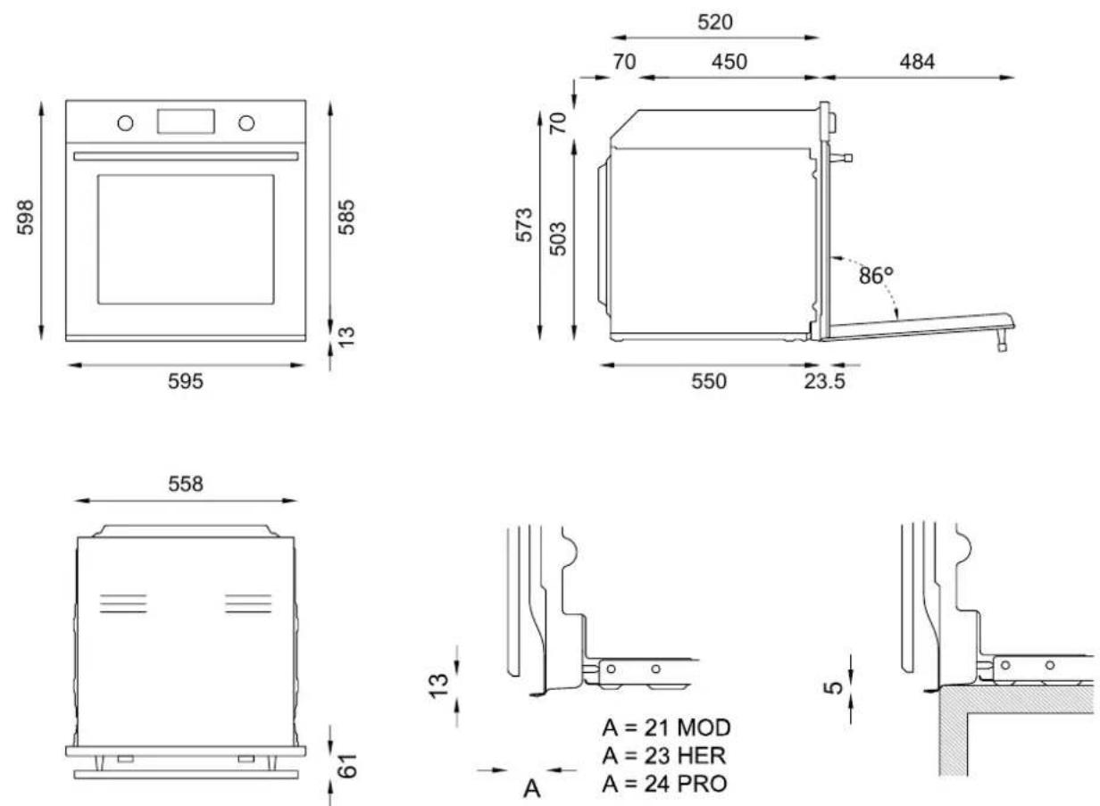
Fig. 3
IMPORTANT INFORMATION
The oven is only suitable for installation inside a fitted kitchen unit or carcass. The sides and surrounding surfaces must be able to withstand temperatures of up 90°C.
Installation of the appliance must be performed in accordance with the provisions of applicable legislation.
INSTALLATION UNDERNEATH A BUILT-IN HOB
The clearance between the oven and the kitchen units or other installed appliances must be enough to ensure sufficient ventilation and air discharge.
If installed under a hob, space must be left between the bottom of the hob and the top of the oven to allow for ventilation of the entire compartment (see figure Fig. 6).
Provide for an opening in the rear of the carcass to Any ventilation openings required for the hob are to be allow for oven ventilation. Lack of sufficient ventilation added to those required by the oven.
could compromise oven performance.
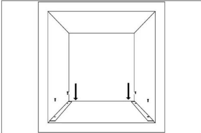
Use the brackets provided to mount the oven on the unit.oven being installed in combination with a hob from another manufacturer.
natural_image
Simple line drawing of a 3D rectangular frame with two vertical arrows indicating downward forces or directions (no text or symbols)Fig. 4

text_image
585 - 595 560 min 60 x 560 560 - 570 60 x 560 60mm x 560mm =336cm²Fig. 5
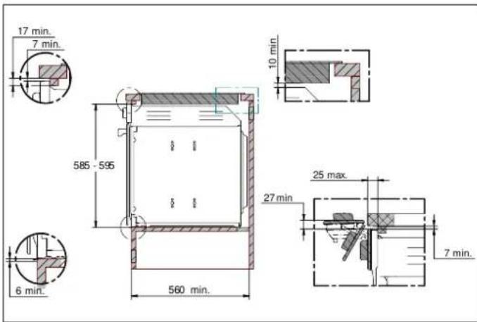
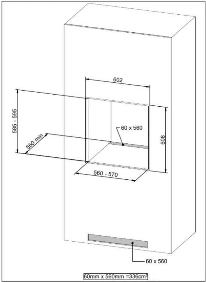
The clearance between the oven and the kitchen units must be enough to ensure sufficient ventilation and air discharge. Ensure there is an opening in the top or rear of the carcass as shown in the figure.
text_image
585 - 595 560 min 602 60 x 560 608 560 - 570 60 x 560 60mm x 560mm =336cm²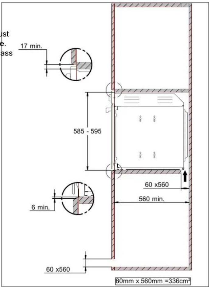
text_image
ust e. ass 17 min. 585 - 595 60 x560 560 min. 6 min. 60 x560 60mm x 560mm =336cm²Fig. 8
Fig. 7
FIXING THE OVEN
- Position the appliance into the carcass with the help of a second person.
- Do not use the door or handle to position the oven.
- Check that the oven is correctly aligned with the units.
- Check that the door opens correctly.
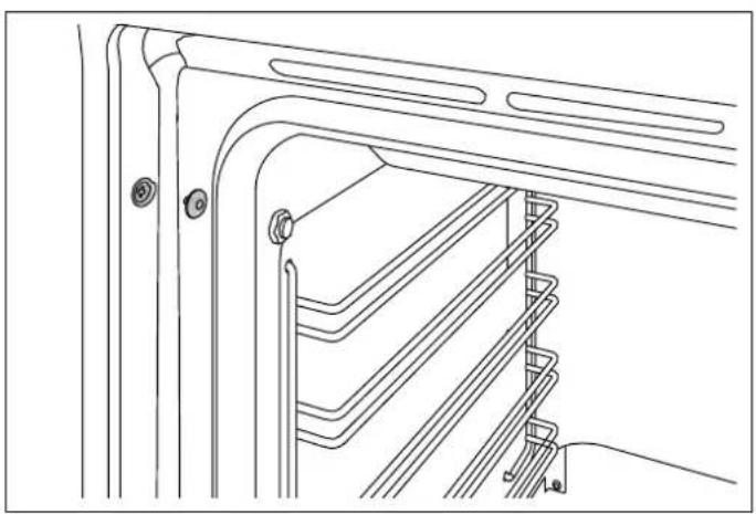
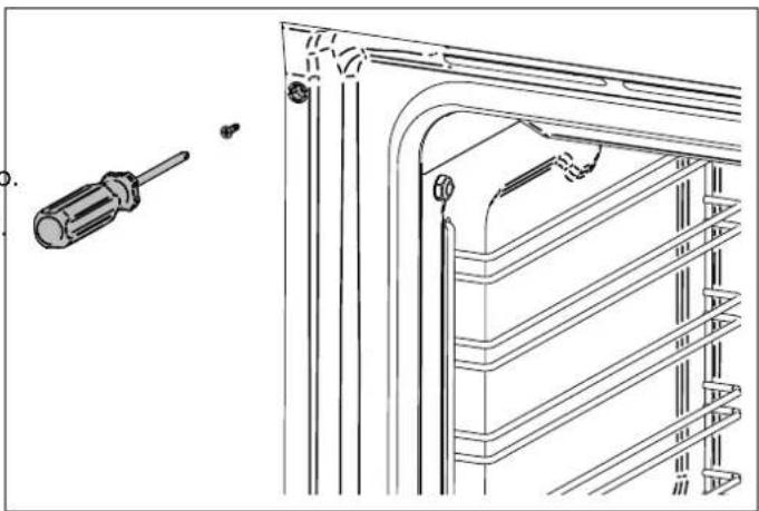
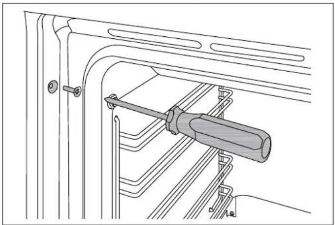
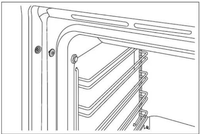
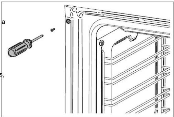
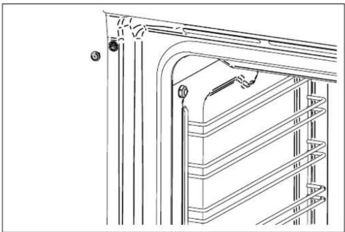
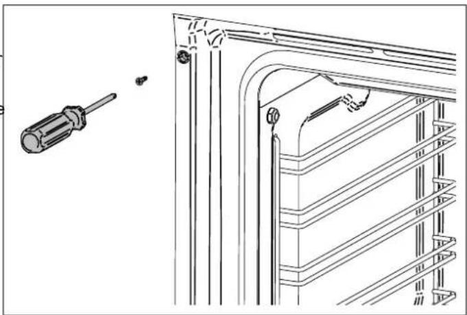
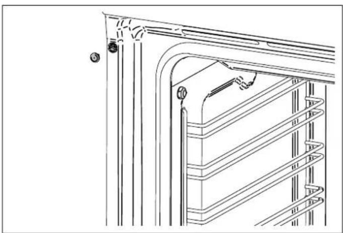
- Fasten the oven to the carcass with the supplied screws, ensuring that the oven remains centered.
• Cover the screws with the caps.
natural_image
Technical line drawing of a mechanical assembly with a screwdriver inserted into a housing (no text or symbols)Fig. 9
natural_image
Technical line drawing of a mechanical or architectural component with layered structure and mounting holes (no text or symbols)Fig. 10
natural_image
Technical line drawing of a mechanical assembly with a screwdriver and bracket (no text or symbols)Fig. 11
natural_image
Technical line drawing of a cabinet or rack structure with no visible text or symbolsFig. 12
ELECTRICAL CONNECTION
Voltage 220–240 V
The electrical connection must be made in accordance with applicable standards and legislation.
| Frequency | 50/60 Hz |
| Max. power 2800 W | |
| Max current draw | 13 A |
| Cable type | 3x1.5mm ^2 |
Before making the connection, check that:
• The characteristics of the mains power supply are compatible with the data shown on the label.
- The circuit wiring and outlet are equipped with a compliant earth connection.
Connection to the mains power supply via a socket:
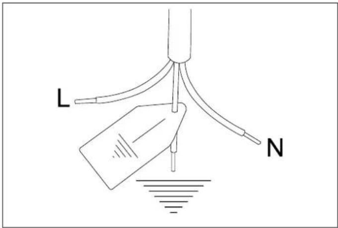
- Fit the power cable with a regulation plug, which must be suitable for the rated load specified on the appliance data plate. Connect the cores of the cable in accordance with the figure Fig. 13, ensuring you follow the harmonized wiring color scheme:
REPLACING COMPONENTS
Isolate the appliance's power supply before performing any maintenance.
Contact an authorized service center if functional components require replacement.
Fit the power cable with a regulation plug, which must be suitable for the rated load specified on the appliance data plate. Connect the cores of the cable in accordance with the figure Fig. 13, ensuring you follow the harmonized wiring color scheme:
• letter L (live) = brown wire;
• letter N (neutral) = blue wire;
- earth symbol = yellow/green wire

CAUTION
If the power cable requires replacement, the installer/maintenance technician must use H05VV-F cable and leave the earth conductor around 2 cm longer than the live and neutral wires. The instructions given for the initial electrical connection must also be complied with.
text_image
L NFig. 13
- Position the power supply cable in such a way that it is not resting against the rear of the oven, that it is not in contact with sharp edges and will not reach a temperature of 90°C at any point.
- Do not use adapters, extension leads, gangsockets etc. as these could cause loose contacts and overheat.
Hard-wired to the mains circuit:
- The circuit must be fitted with an omnipolar circuit breaker of suitable capacity for the appliance's rated load.
• The earth conductor must not be switched by the breaker and must be connected to the earthing system.
• As an alternative, an RCD may also be used.
CONTROL PANEL
TWO-KNOB OVEN CONTROLS

text_image
1 2 3FULL-TOUCH OVEN CONTROLS
natural_image
Simple diagram with a rectangle centered on two horizontal lines, labeled '1' at the bottom (no text or symbols within the diagram itself)Fig. 15
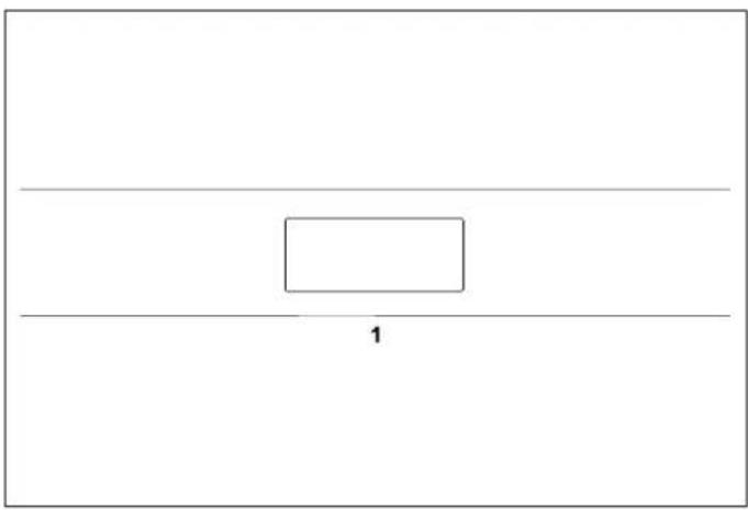
Fig. 14 1) Touchscreen display
1) Function selector
2) Touchscreen display
3) Temperature selector

ON/OFF Turns the oven on or off

CANCEL/PREVIOUS MENU
Cancels or returns to the previous menu

CONFIRM Confirm or continue

SETTINGS
Settings menu

NOTE
For temperature settings and functions, touch the icon on the display.

ON/OFF Turns the oven on or off

CANCEL/PREVIOUS MENU
Cancels or returns to the previous menu

CONFIRM Confirm or continue

SETTINGS
Settings menu
OVEN FUNCTIONS
| SYMBOL DESCRIPTION 11 FUNCTIONS 11 PYROLYTIC FUNCTION | |||
 | Convection | • | • |
 | Fan | • | • |
 | Static | • | • |
 | Fast preheat • • | ||
 | Turbo | • | • |
 | Bottom bake | • | • |
 | Grill | • | • |
 | Fan grill • • | ||
 | Assistant | • | • |
 | Specials • • | ||
 | Hydroclean • | ||
 | Clean | • | |
FIRST USE
FIRST SWITCH-ON
Run your finger up and down the display to scroll through Once the oven has been connected to the power supply, the menu. enter the settings menu (see settings chapter) and set the following:
To activate a menu function, press and hold on the required function for at least two seconds. The chosen function will be selected as soon as you remove your finger from the clock display. • clock format
Touch a parameter on the display to modify it. For time, measurement units brightness and audio settings, confirm with the play button.
PRELIMINARY OPERATIONS
- Remove films and any packaging residues from the inside and outside of the oven.
- Remove and wash all the accessories.
- Operate the oven for 30 min. at a temperature of 250^ without placing food inside (it is normal for processing residues to produce smells and smoke during this operation).
- Leave the oven to cool.
- Open the oven door and leave it to air for 15 minutes.
- Clean the inside of the oven with a moist cloth and neutral detergent (do not use scouring powders).
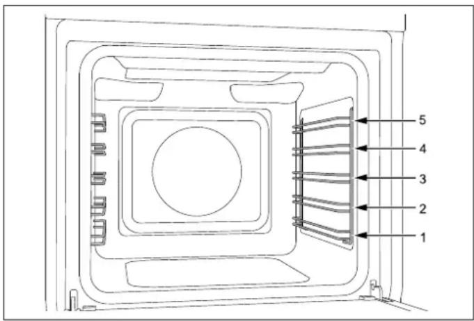
RACK POSITIONING
Insert racks and trays into the side guides until they come to a complete stop in order to prevent contact with the ove door.
When removing accessories beyond halfway they are blocked to facilitate removing dishes.
The oven has five cooking levels indicated on the right-hand side of the front of the oven.
text_image
1 2 3 4 5Fig. 16
COOLING
The oven is equipped with a variable-speed cooling system which operates during cooking.
An air flow between the control panel and the oven door keeps the controls at a temperature that enables their use.
The cooling system switches on and off automatically (it is normal for it to continue operating even after the oven is switched off).
PREHEATING
Most recipes require the oven already to be at the cooking temperature when the food is placed inside.
The preheating time depends on the temperature set and the number of accessories in the oven.
OVEN LIGHT
The oven light comes on automatically when the door is opened and remains on during standard cooking functions.
WATER HARDNESS
Do not use distilled water or tap water with a high chlorine content (> 40 mg/l), or other liquids.
Use only cold, clean tap water.
If the water in your area is very hard, use softened water or mineral water.
- Do not use sparking water.
- Do not use water with hardness dH > 7 (1.3 mmol/l).
USING TWO-KNOB OVENS
1) Insert the rack at the required level.
2) Select the oven function by rotating the knob.
3) Set the temperature by turning the knob clockwise.
4) If necessary, set timed cooking via the touchscreen display.
An audible warning and visual message indicate when the set temperature is reached. Return at least one knob to the zero position at any time to stop cooking.
Run your finger up and down the display to scroll through the menu.
To activate a menu function, press and hold on the required function for at least two seconds.
The chosen function will be selected as soon as you remove your finger from the display. Touch a parameter on the display to modify it.
1) Insert the rack at the required level
2) Touch the power button twice to turn the oven on the appliance is already on)
3) Scroll through the functions menu and choose the required cooking method
4) Scroll to select the required temperature
5) If necessary, set timed cooking via the touchscreen display.
6) Touch the Play button to start cooking, or wait (15 seconds) for it to start automatically.
An audible warning and visual message indicate when the set temperature is reached. Touch the power button at any time to stop cooking.
COOKING MODES
The oven has several heating elements, operated individually or in combination to create the various cooking modes.

CAUTION
All cooking operations must take place with the door closed.
CONVECTION
Heat from rear element, distributed by fan.
Cooking on multiple levels, ideal for any type of dish requiring uniform heat.
• Level 2 or 3 for cooking single items
• Levels 2 and 4 for cooking multiple items
• Possible addition of steam (min-med-max levels).
FAN
Heat from above and below distributed by the fan.
^e Cooking on multiple levels, ideal for biscuits and cakes.
Level 2 or 3 for cooking single items
• Levels 2 and 4 for cooking multiple items
• Possible addition of steam (min-med-max levels).
STATIC
Heat from above and below.
Cooking on just one level, ideal for roasts, bread and cakes.
- Roasts on level 2 or 3
- Cakes on level 2 or 3 to ensure they are completely cooked underneath without burning the top.
FAST PREHEAT
Use this function to bring the oven to the required temperature in a short time.
This function is only designed for heating the oven and not for cooking foods.
TURBO
Function which combines Convection cooking and heating from below. Cooking on a single level, ideal for pizza, flatbreads and other foods requiring high temperatures and heat from below.
- Level 1 or 2
• Possible addition of steam (min-med-max levels).
BOTTOM BAKE
Heat from below.
Cooking on just one level, ideal for slow cooking and for warming plates.
At high temperature, use for sweet and savoury pastries which do not require browning.
- Level 2 or 3
GRILL
Heat from top grill. Max recommended temperature 200°C.
Cooking on just one level, ideal for grilling sausages, chops, bacon, fish or toast.
Surface browning after cooking.
- Level 4 or 5
FAN WITH GRILL
Heat from top grill, distributed by fan. Max recommended temperature 175^ C.
Cooking on just one level, ideal for grilling thick foods
The circulation of the heat helps to cook the food through while still grilling it on the top.
- Level 4 or 5
Possible addition of steam (min-med-max levels).
ASSISTANT
See specific chapter
Function with forced air circulation and temperature of 37^ C for drying foodstuffs, flowers and vegetables.
DEFROST
Function with forced air circulation to speed up defrosting of foodstuffs.
WARMING
Function for warming up food; three temperature levels: 60^ C - 76^ C - 93^ C.
PROOFING
Function for leavening dough. It is recommended to insert the foodstuffs with the oven still cold.
Do not open the oven door unless strictly necessary.
SABBATH
Heating method for use during periods of religious observance.
ECO
Fan-assisted cooking function with low power consumption (light deactivated during cooking).
STEAM ONLY
Special function for steam cooking of foods which is not combined with other cooking methods.
AIR FRY
Heat from broil element and air flow convection with fan.
Set the desired temperature according with the recipe (from 180^ C to 250^ C) One reached the settled temperature place the tray with the food in the oven.
Food may be to be removed early and should be checked at minimum recommended time to avoid overcooking/browning.
Use level 4. To get best results use the air fry tray supply with the oven and arrange the food in single layer.
CLEANING
PYROLYSIS
In the self-cleaning cycle, the oven's interior is heated to very high temperatures – over 400^ C – to burn off any f residue. Before starting a pyrolysis cycle, remove all accessories and side racks from the oven, then manually remove any pieces of food and larger residues with a da sponge.
Remove the silicone cap from the meat probe socket and insert the metal cap.
During pyrolysis, the door locks automatically and will only reopen when the oven cools back down at the end of the cycle.
It is normal to see some flaming and smoke develop inside the oven.
After the cleaning cycle, the burned off residue is reduced ^9 to ash and can be easily brushed off with a damp sponge
The complete cycle duration is 120 minutes.
ECO PYRO
Ninety-minute self-cleaning cycle which can be used when there are lower levels of encrusted dirt.
HYDROCLEAN
Twenty-minute low-temperature oven cleaning cycle.
1) Manually remove any pieces of food and larger residue with a damp sponge.
2) Pour 400 ml of water onto the base inside the cavity.
3) Spray a solution of water and washing-up liquid (using spray bottle) onto the side walls.
4) Activate the function (duration approx. 20 min).
5) after cooling, dry with a soft cloth.
HYDROCLEAN (ELEVEN-FUNCTION OVEN ONLY)
Twenty-minute low-temperature oven cleaning cycle.
1) Manually remove any pieces of food and larger residues with a damp sponge.
2) Pour 400 ml of water onto the base inside the cavity.
3) Spray a solution of water and washing-up liquid (using spray bottle) onto the side walls.
4) Activate the function (duration approx. 20 min).
5) Once it has cooled back down, dry with a soft
STEAM
STEAM-ASSISTED COOKING
During operation of the appliance with the addition of steam, steam is dispensed inside the oven at different intervals and with various intensities.
Adjusting the steam percentage and temperature will achieve improved cooking results:
- crunchy crust
- shiny surface
- soft, juicy center
- minimal reduction in volume
With fan-assisted functions, it is possible to select the percentage of steam to be added during cooking.
Use only heat- and corrosion-resistant cookware or food-grade stainless-steel containers.
When cooking on multiple levels, check that there is space between the different levels in order to allow the steam to circulate.
If the temperature probe is not being used during steam
cooking, insert the silicone cap in the socket.
If the oven door is opened during operation, only the fan will turn off. Once the door is closed, the appliance will resume operation.
To shut off the appliance in advance or adjust the set stear quantity, press the steam icon on the display.
STEAM LEVELS
The addition of steam ensures dishes are cooked gently, keeping the interior juicy.
Three levels of steam can be selected for fan-assisted cooking programs:
• MIN. Ideal for meat, poultry and baked dishes.
- MED. Ideal for stewed/braised meat, bread and other leavened dishes.
- MAX Ideal for delicate dishes such as custards, flans, timbales and fish.
STEAM COOKING
Ideal for fish and vegetables. The steam envelops the dish, preventing the loss of nutrients, while the color and flavor are unchanged.
PUMP
During operation and after switching off, an audible hum indicates that the pumps are operating.
WATER RESERVOIR
The water reservoir is located behind the control panel. Before use, open the control panel and fill the water reservoir. If the water in the reservoir runs out during a steam function, a buzzer will sound and a message be displayed instructing you to top it up.
STEAM ACCESSORIES
For steam cooking, use racks or perforated trays.
DERIVATIVE FUNCTIONS
VACUUM
To cook vacuum-packed foodstuffs, set steam cooking with a temperature between 60° and 90°C. Make sure that the vacuum bags are heat-proof.
When cooking with vacuum bags, more condensation will form on the base of the oven than with other types of cooking.
REGENERATION
Delicately reheat previously cooked food, or prepare baked goods in advance.
Set fan-assisted cooking at 120^ C with the addition of Medium Steam for 7 minutes.
The time required may vary on the basis of the quantity of food or the container used.
FOOD PRESERVATION
To complete sterilization of jars of preserves in order to prolong their duration, set steam cooking for at least 20 min. at a temperature of 100^ C (the duration may vary depending on the size of the jars).
STERILIZATION
Clean containers after use with a bottle brush and wash in the dishwasher. Position them on the oven rack so that they are not touching, with the mouth facing downwards.
To sterilize dishes and baby bottles, set steam cooking at 100^ C for 40 min.
Dry with a clean towel.
CONDENSATION
It is normal for condensate to form on the inside of the over-door glass and on the control panel when cooking especially water-rich foods.
The condensate will evaporate on its own during cooking.
Programs with steam, due to their nature, generate condensation throughout the oven, and particularly on the inside door glass. When using steam cooking functions, particularly at low temperatures, remember to empty the drip tray.
COOKING GUIDANCE
The temperature set and cooking time may vary slightly from one oven to another. Small adjustments compared to the recipe may be necessary.
- Increasing the temperature does not reduce cooking times.
• Cooking times depend on the weight, thickness and quality of the food.
Always place food in the middle of the shelf.
- Choose the cooking level in accordance with the recipe and your own experience.
- Leave a gap of at least 3 cm between oven dishes and the sides of the oven to enable heat to circulate of effectively.
- Use light-coloured aluminium trays when baking small pastries.
- Use dark metal baking pans for cakes and biscuits because they help to absorb the heat.
• Turn and stir foods so that they are heated evenly.
- For new recipes, set the temperature at the bottom of the stated range and the shortest time, then assess how cooking is proceeding and extend the time if necessary.
When steam cooking, position foodstuffs so that they are not overlapping.
- Do not open the oven door during cooking to ensure the correct moisture level for the food.
ENERGY SAVING
- Open the oven door only when necessary to avoid wasting heat.
- Keep the inside of the oven clean.
- Remove any accessories not currently being used.
- Shut off the oven a few minutes before the time normally used, allowing the residual heat of the oven to finish cooking.
- Let frozen foodstuff s thaw completely before placing them in the oven.
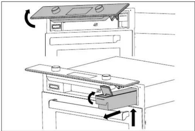
WATER RESERVOIR
The water reservoir is located behind the control panel.
After setting the temperature function and steam quantity:
- Confirm opening of the control panel
- Lift the panel upwards with both hands until it clicks.
• Gently lift the reservoir and pull it out partially
- Open the lid and fill with water to the indicated level.
- Close the lid again.
- Reposition the reservoir by pushing it all the way until locks in place.
- Lift the control panel upwards to release it, and then lower it until it is fully closed.
The water reservoir can be completely removed for cleaning or filling.
natural_image
Line drawing of a refrigerator interior showing door, drawer, and drawer with directional arrows indicating movement (no text or symbols)Fig. 17
- Touch the OK and ▶ icons simultaneously and then confirm by pressing OK on two-knob ovens, or press the + and OK icons simultaneously and then confirm by pressing OK on touchscreen ovens.
- Confirm
- Lift the panel upwards with both hands until it clicks.
Gently lift the reservoir and pull it out completely.
• Empty the reservoir, removing the lid.
- Wash with soapy water and rinse thoroughly with clean water.
t Dry with a soft cloth.
- Reassemble the reservoir
- Reposition the reservoir by pushing it all the way until it locks in place.
- Lift the control panel upwards to release it, and then lower it until it is fully closed.
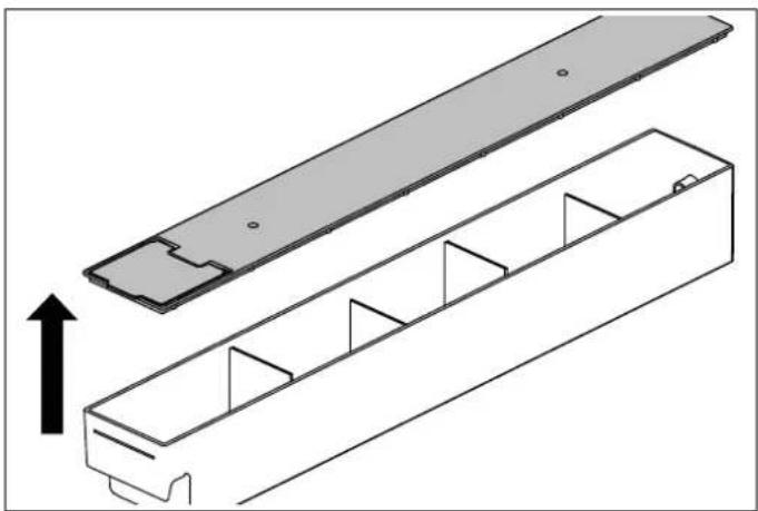
natural_image
Technical line drawing of a mechanical component with internal channels and a top plate, showing an upward force indicator (no text or symbols)Fig. 18
It is possible to access the reservoir at any time: touch the do not wash the reservoir in the dishwasher.
OK and ▷ icons simultaneously and then confirm by pressing OK on two-knob ovens, or press the + and OK icons simultaneously and then confirm by pressing OK on touchscreen ovens.

CAUTION
Each time the reservoir is removed, check that the seals are intact and correctly positioned.
During steam cooking, the condensation that forms on the door is collected in the drip tray.
The water circuit is automatically drained into the reservoir at the end of cooking.

CAUTION
The water in the reservoir may be boiling hot: check that the water has cooled down before removing the reservoir.
DRIP TRAY
During steam cooking, the condensation which forms on the door is collected in the drip tray. It must be dried at the end of every steam cooking process:
- Leave the oven to cool.
- Open the oven door.
- Mop up the water in the drip tray with a soft cloth.
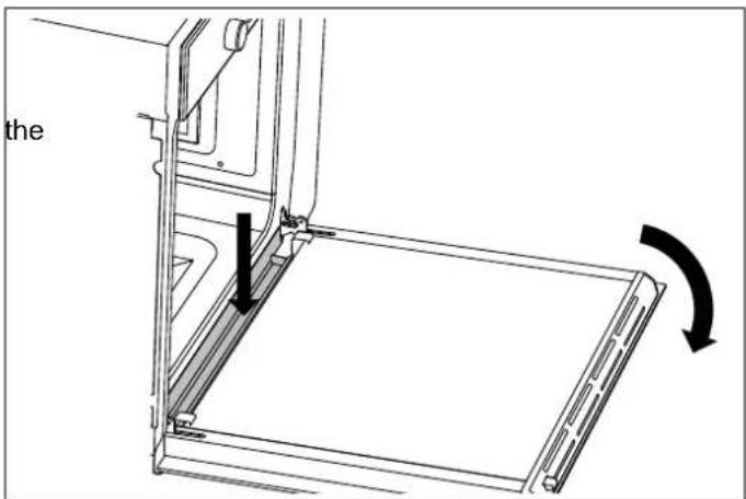
text_image
theFig. 19
COOKING GUIDELINES
The times given in the table do not include preheating times and are provided only as a guide.
| FOOD | WEIGHT (KG) | FUNCTION | TEMPERATURE (°C°C) | TIME (MINUTES) |
| Lasagna | 3-4 Static 220-230 45-50 | |||
| Baked pasta | 3-4 Static 220-230 45-50 | |||
| Roast veal 2 Fan 180-190 90-100 | ||||
| Pork loin 2 Fan 180-190 70-80 | ||||
| Sausages | 1.5 | Fan grill | 175 15 | |
| Roast beef 1 | Fan | 200 | 40-45 | |
| Roast rabbit 1.5 | Convection | 180-190 70-80 | ||
| Turkey breast | 3 Fan 180-190 | 110-120 | ||
| Roast pork neck | 2-3 | Fan 180-190 | 170-180 | |
| Roast chicken | 1.2 | Fan 180-190 65-70 | ||
| 1st side 2nd side | ||||
| Pork chops | 1.5 | Fan grill | 175 | 15 5 |
| Spare ribs | 1.5 | Fan grill | 175 | 10 10 |
| Bacon | 0.7 | grill | 200 | 7 8 |
| Pork fillet | 1.5 | Fan grill | 175 | 10 5 |
| Beef fillet | 1 | grill | 200 | 10 7 |
| Rainbow trout | 1.2 | Fan 150-160 35-40 | ||
| Monkfish | 1.5 | Fan | 160 | 60-65 |
| Turbot | 1.5 | Fan | 160 | 45-50 |
| Pizza | 1 | Turbo | MAX | 8-9 |
| Bread | 1 | Convection | 190-200 25-30 | |
| Focaccia | 1 Fan 180-190 20-25 | |||
| Bundt cake | 1 | Convection | 160 | 55-60 |
| Jam tart | 1 | Convection | 160 | 35-40 |
| Ricotta cake | 1 | Convection | 160-170 55-60 | |
| Stuffed tortellini | 1 Fan | 160 | 20-25 | |
| Sponge cake | 1.2 | Convection | 160 | 55-60 |
| Profiteroles | 1.2 | Fan | 180 | 80-90 |
| light sponge cake | 1 | Convection | 150-160 55-60 | |
| Rice cake | 1 | Fan | 160 | 55-60 |
| Brioches | 0.6 | Convection | 160 | 30-35 |
USING THE TOUCHSCREEN DISPLAY
DROP-DOWN MENU
The drop-down menu contains some functions which can be activated with the oven off.
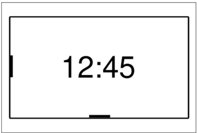
text_image
12:45Fig. 20
Scroll the FLAP _ symbol upwards to open; scroll the FLAP _ symbol downwards to close.
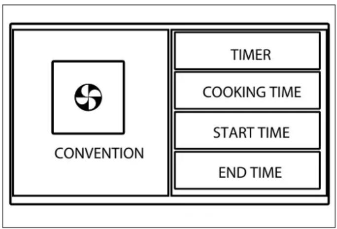
TIMER
Countdown timer: when it finishes, a buzzer will sound. timer does not stop the cooking operation.
Scroll to set; the timer starts automatically.
LIGHT
To turn the oven light on and off with the door closed.
OVEN PREHEATING
Function to bring the oven to the required temperature in short period of time.
This function is only designed for heating the oven and r for cooking foods.
SCREEN BRIGHTNESS
To set or change the display brightness.
SETTINGS MENU
Touch the settings button to enter the menu.
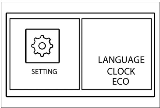
text_image
SETTING LANGUAGE CLOCK ECOFig. 21
BRIGHTNESS
To set or change the display brightness.
AUDIO
To set or change the volume of the sounds.
LANGUAGE
To select the preferred appliance language (the default is English).
CLOCK
To set or change the time.
SHOWROOM MODE
Reactivates the heating elements for showrooms use.
ECO MODE
To reduce energy consumption.
MANAGING THE TIME FUNCTIONS
flowchart
graph TD
    A["CONVENTION"] --> B["TIMER"]
    A --> C["COOKING TIME"]
    A --> D["START TIME"]
    A --> E["END TIME"]
Fig. 22
Touch the clock icon to modify the duration of the current cooking program.
After setting the function and temperature, press the clock icon several times ⏻) and choose a time function.
TIMER
For setting the countdown at the end of which a beep is emitted and an alert message is displayed. The timer does not stop the cooking operation.
Scroll to set; the timer starts automatically.
COOKING TIME
To set a countdown timer, at the end of which cooking will be stopped, an audible warning will sound and a message will be displayed.
Scroll to set; the cooking time starts automatically.
START AT
To set the start time and duration of cooking. When the time arrives, an audible warning will sound indicating the start of cooking. When the set duration has elapsed, cooking will stop, an audible warning will sound and a message will be displayed.
Scroll to set first the start time and then the cooking time.
ENDS AT
To set the cooking end time and duration (the start time will be calculated by the appliance).
An audible warning will sound when cooking begins. When the set duration has elapsed, cooking will stop, an audible warning will sound and a message will be displayed.
Scroll to set first the end time and then the cooking time.
Touch the Power button, or else return the function knob to the off position, to stop cooking at any point.
To change the duration of cooking in progress, touch the clock icon.

NOTE
If the time functions are not managed, the duration of the cooking must be managed manually.
TEMPERATURE PROBE (WHERE AVAILABLE)
The temperature probe allows you to choose the level of cooking by measuring the internal temperature of the food.
PROGRAMMING THE PROBE
1) Insert the sharp end of the probe into the food. For the best results, the tip must be as close as possible to the center point of the food, and not in contact with fat, bone or hollow areas.
(2) Choosing the cooking function and temperature
3) Plug in the probe inside the oven (on the top left-hand side).
4) Set the temperature you wish to obtain at the center of the food.
When the set temperature is measured by the probe, smoking will stop, an audible warning will sound and a message will be displayed.

NOTE
When using the temperature probe, only the Timer function is available.
ASSISTANT
The assistant function helps you manage a range of cooking, temperature and time functions for each type of food.
The system does not provide recipes, but helps the oven get the best out of yours.
It is possible to create new sequences and store them for future use.
RECIPE MANAGEMENT
Preset cooking sequences.
1) Choose the required food category.
- Meat
- Poultry
- Fish
- Desserts
- Bread
- Pizza
- Pasta
- Vegetables
2) Choose the required dish.
3) Select the weight and level of cooking, where required.
4) Use the temperature probe where required.
5) Press play.
At the end of cooking, an audible warning will sound and a message will be displayed. Touch the power button, or else return the function knob to the off position, to stop cooking.
MY COOKBOOK
Saved personal cooking sequences
1) Select the required recipe from the saved ones.
2) Press play.
At the end of cooking, an audible warning will sound and a message will be displayed. To stop cooking, press the power button. To delete a saved recipe, select the name and drag it from the right to the left-hand side and confirm.
SET
For setting and saving complex cooking sequences. Up to three functions in sequence can be selected.
1) Selection function 1
2) Set cooking function, temperature and duration.
3) Repeat for functions 2 and 3, where necessary.
4) Press play to run the recipe.
5) Before activating cooking, you can decide whether or not to save the recipe; if saving, an on-screen keyboard will be displayed to name and save it.
6) Once saved, touch the play button to start cooking.
Use the My Cookbook function to bring up the saved recipe.
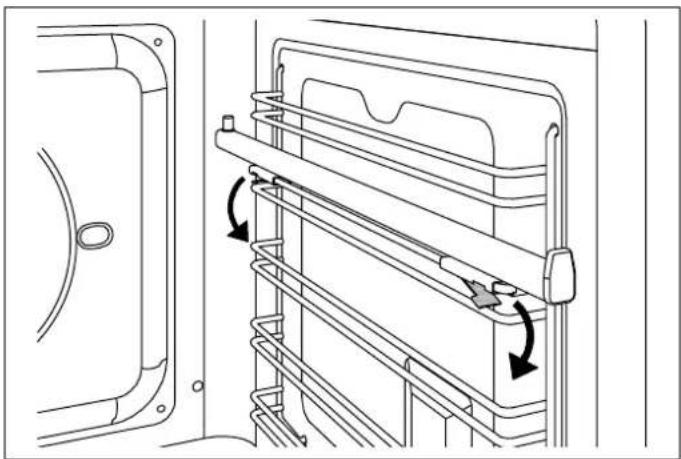
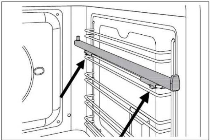
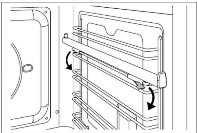
TELESCOPIC RAILS
The telescopic rails can be installed on any level of the oven guides.
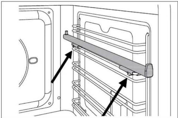
- Locate the two spring clips (front and rear) on the telescopic rail.
- Locate the pin indicating the rear part of the rail.
- Position the telescopic rail flush with the upper edge of the selected level.
- Insert the front clip, pushing it towards the side guide.
- Insert the rear clip, pushing it towards the side guide.
- Repeat the insertion operation for the other side.
- Pull both rails out and position the oven rack or tray between the rear pin and the front stop.
natural_image
Technical line drawing of a door frame with a horizontal panel and two arrows indicating assembly or movement (no text or symbols)Fig. 23
natural_image
Technical line drawing of a door frame with horizontal metal racks and directional arrows indicating movement (no text or symbols)Fig. 24
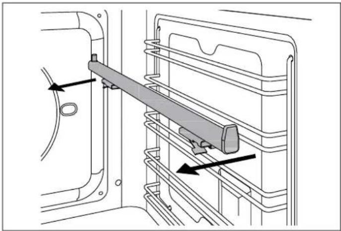
REMOVING THE TELESCOPIC RAILS
- Locate the two spring clips (front and rear) on the telescopic rail.
- Keeping the front clip pushed down, pull the rail towards the interior of the oven.
- Repeat the operation for the rear clip.
natural_image
Technical diagram of a mechanical assembly with a lever and guide mechanism (no text or symbols)CLEANING THE APPLIANCE
SEAL
Before performing any manual cleaning operation, wait for Wipe with a damp cloth.
all parts to cool down and isolate the oven from the electrical supply.
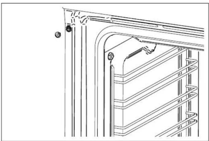
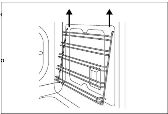
REMOVING THE SIDE GUIDES
Scrupulous care of your oven will help keep it in excellent condition for many years to come.
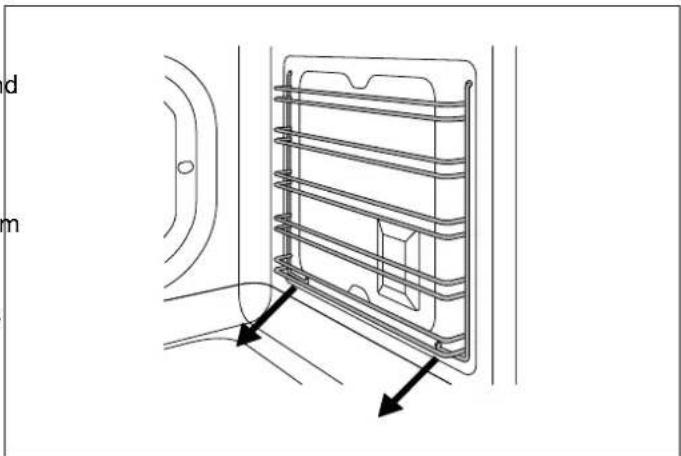
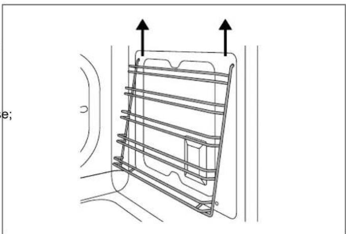
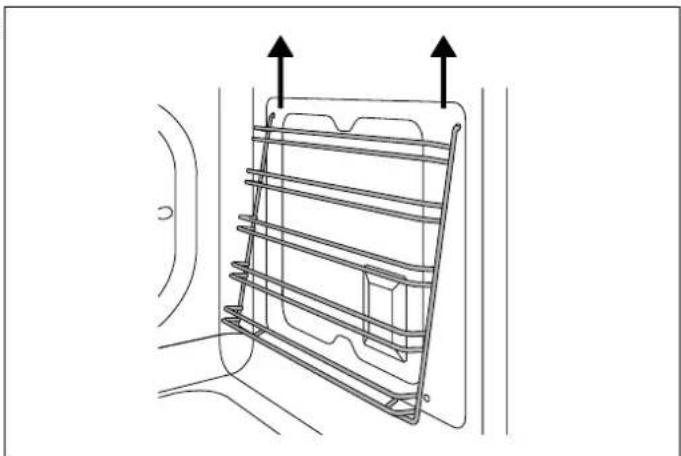
Identify the two hooks at the bottom of the guide assembly and pull them gently downwards.
CLEANING ENAMELLED OR PAINTED PARTS:
- Pull the guide assembly away from the side of the oven and remove by pulling the upper hooks of the assembly upwards from the side of the oven.
To maintain the characteristics of the enameled components, they should be cleaned frequently with soapy water. Never use scouring powders.
Remove the side guide assembly from the oven.
Do not leave acidic or basic substances (vinegar, lemon juice, salt, tomato juice etc.) sitting on enameled parts, and do not wash enameled parts when they are still hot.
CLEANING STAINLESS-STEEL PARTS:
Clean the components with soapy water and then dry them with a soft cloth, following the direction of the brushed finish. The shine can be maintained by periodic use of commonly available products. Do not use harsh/aggressive detergents such as:
• Limescale removers
- Bleach
- Hydrochloric acid
• Ammonia cleaners
• Scouring pads or powders.
Immediately remove limescale, grease, starch or egg-white stains.
CLEANING THE DOOR GLAZING
To degrease, use washing-up liquid and vinegar, then rinse; otherwise, clean with washing-up liquid, rinse, then pass over with a moist cloth before drying.
To remove encrusted food, soak with soapy water or washing-up liquid for a few minutes. After a few minutes, rinse off then dry with a soft cloth.
Avoid anti-limescale, abrasive and multi-purpose products, as they will affect the look of the glass after a while.
natural_image
Technical line drawing of a door frame with horizontal insulation and two directional arrows indicating movement (no text or symbols)Fig. 25
natural_image
Technical line drawing of a mechanical component with two upward arrows indicating motion or assembly (no text or symbols)Fig. 26
CLEANING THE OVEN RACKS
Do not wash the racks in the dishwasher.
Immerse them in hot soapy water, then wipe with a non-abrasive sponge before rinsing and drying with a soft cloth.
CLEANING HANDLES
Clean the components with soapy water and then dry them with a soft cloth, following the direction of the brushed finish. Never use scouring powders or pads.
REPLACING THE OVEN LIGHT

CAUTION
Isolate the oven's power supply before changing the light bulb. DO NOT touch the bulb with your bare hands.
Type of light bulb: G9 halogen, 220 V, 40 W
- Ensure that the oven is off and cool.
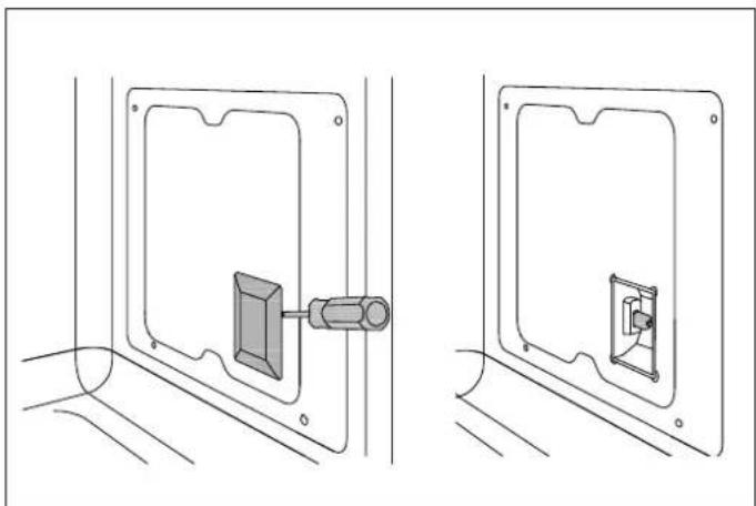
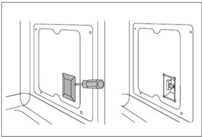
• If necessary, remove the side guides from the oven. - Slide the tip of a flat-head screwdriver between the glass cover and the bulb housing, taking care not to damage the seal.
• Gently turn the tip of the screwdriver to loosen the glass while keeping it in position with your fingers to prevent it falling and breaking.
- Remove the glass and take out the old halogen bulb.
- Insert a new halogen bulb in the holder. DO NOT touch the bulb with your bare hands.
REPLACING RESERVOIR SEAL
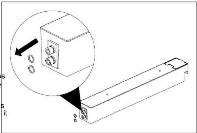
Each time the reservoir is removed, check that the seals are intact and correctly positioned. Replace them with those supplied if they should be damaged.
text_image
Technical diagram showing a mechanical assembly with labeled parts and an inset magnified view of a component with bolts and pins.Fig. 28
natural_image
Technical line drawing showing two views of a mechanical component mounted on a panel (no text or symbols)Fig. 27
- Press the glass cover back on and reposition the side guide assembly.
- Refit the side guide.
- Reinstate the power supply.
CLEANING THE INTERNAL DOOR GLASS
The internal door glass can be easily removed for cleaning. There is no need to remove the door to clean the glass.
The glass can be cleaned in place, or removed for cleaning.
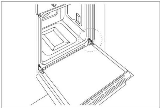
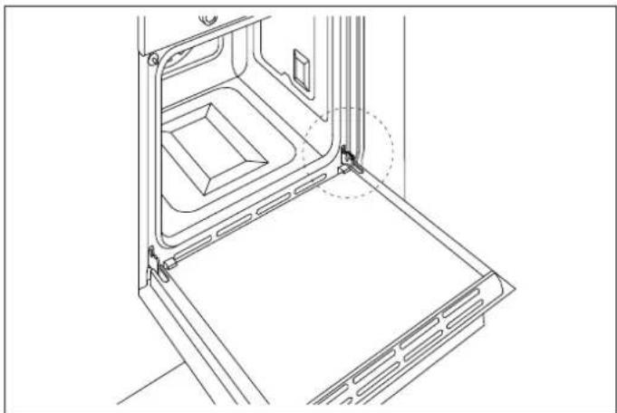
• Fully open the oven door.
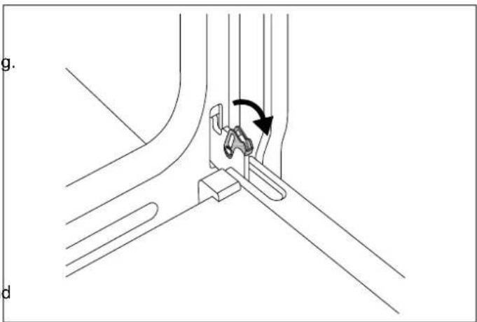
• Fully open the blocking levers for both hinges.
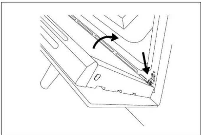
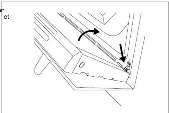
- Slowly close the door until it blocks, checking that the levers have blocked the door.
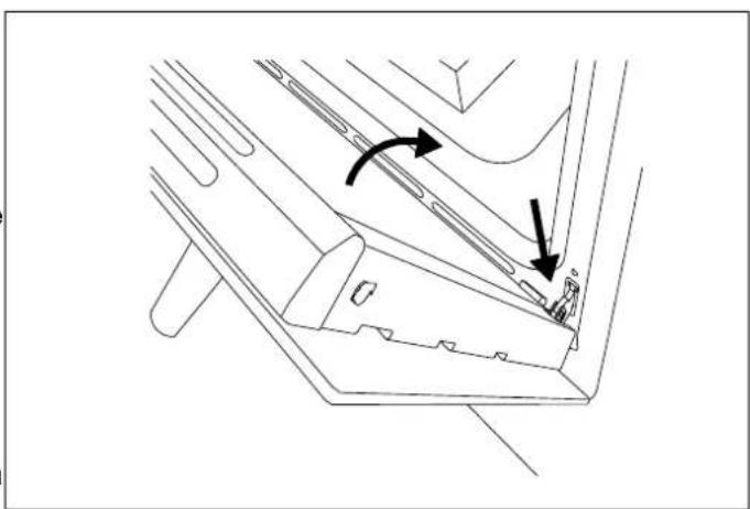
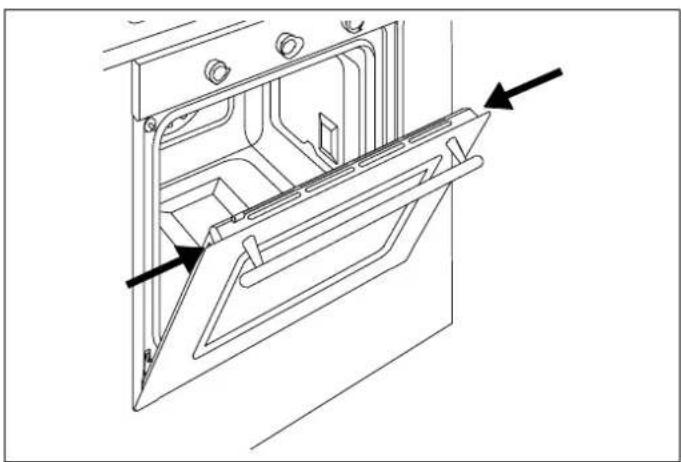
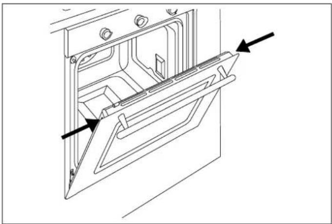
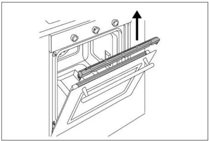
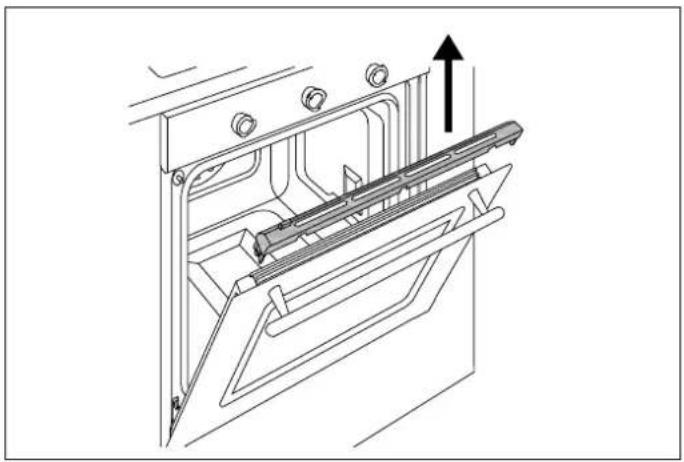
- Remove the top cover of the door by pressing the round buttons on the left and right.
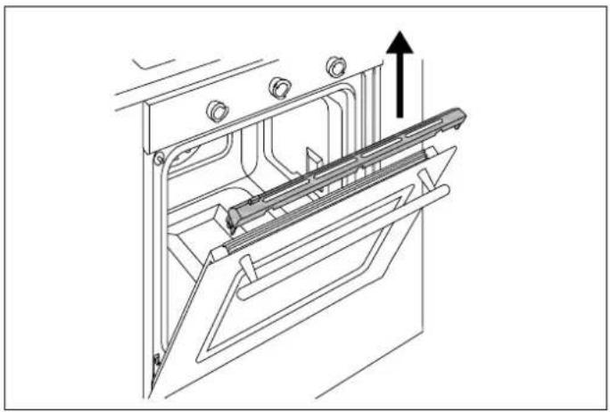
- Lift the top cover and remove.
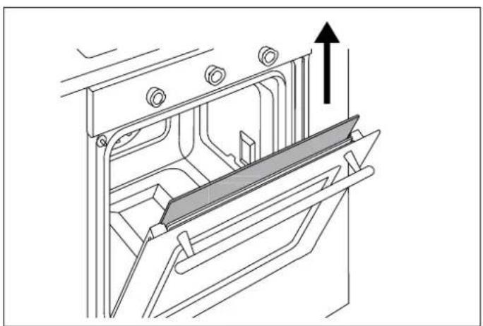
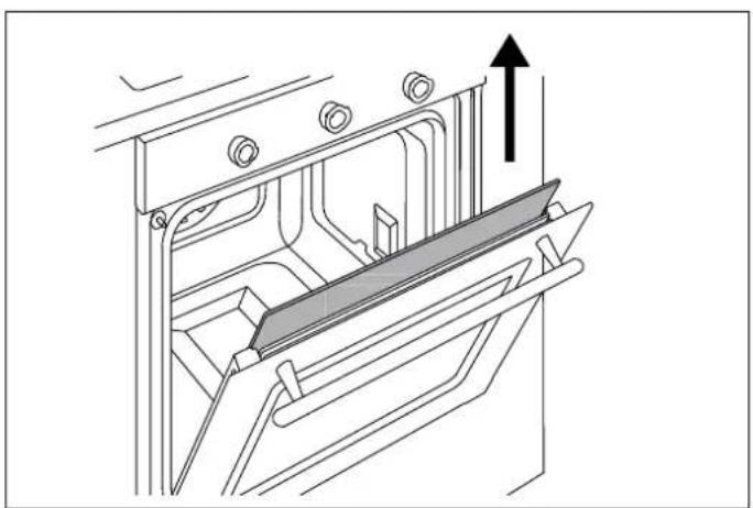
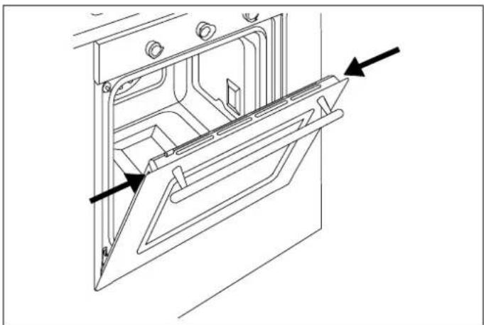
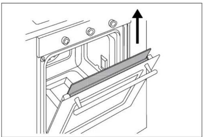
Paying close attention to the sides of the glass:
- Slide the panes of glass out.
- Clean the glass.
- Repeat the operations above in reverse to reassemble the door.

CAUTION
The markings on the glass must face outwards.
If the hinges are not correctly blocked and the internal glass is removed, the door can close by itself.
natural_image
Technical line drawing of a mechanical assembly with no visible text or symbolsFig. 30
natural_image
Technical line drawing of a mechanical component with two arrows indicating motion or force direction (no text or symbols)Fig. 31
natural_image
Technical line drawing of a door frame with ventilation grilles and a dashed circle highlighting a component (no text or symbols)Fig. 29
natural_image
Technical line drawing of a door frame with internal compartments and mounting holes (no text or symbols)Fig. 32
natural_image
Technical line drawing of a mechanical assembly with an upward arrow indicating motion or force (no text or symbols present)Fig. 33
natural_image
Technical line drawing of a mechanical assembly with an upward arrow indicating motion (no text or symbols present)Fig. 34
THE OVEN DOES NOT WORK
Is the oven receiving power? Check the switch or fuse. Disconnect the oven from the power supply for around minute by unplugging it or turning it off at the circuit breaker.
THE OVEN DOES NOT HEAT UP
Check that showroom mode is not enabled.
Check that a time function is not active. Disconnect the oven from the power supply for around one minute by unplugging it or turning it off at the circuit breaker.
THE KNOB WILL NOT STAY IN PLACE.
The knob clip is broken: call customer service for a replacement.
THE CONTROLS ARE VERY HOT
This is normal if the door is left open for a prolonged period of time with the oven running.
Check that the door closes correctly and that the cooking system is operational.
FOOD IS OVERCOOKED.
When using a fan-assisted function, remember to lower the cooking temperature by 20°C.
FOOD IS UNDERCOOKED
When cooking large quantities of food, the cooking time must be increased proportionally.
Check that there is sufficient space around the oven dish allow heat to circulate correctly.
Check that the door closes correctly.
Have a technician check the actual mains voltage.
CONDENSATION FORMS ON THE OVEN DOOR GLASS
It is normal for condensate to form on the inside of the oven door glass and on the control panel when cooking particularly water-rich foods. The condensate will evaporate on its own during cooking.
Pre-heat the oven to reduce condensation build-up.
SMOKE FORMS DURING COOKING
It is normal for smoke to form inside the oven when cooking particularly fatty foods.
When cooking with the grill, a certain quantity of smoke is normal.
THE CLEANING PROCEDURE IS INTERRUPTED BEFORE IT FINISHES.
A power failure has occurred. Check that the ventilation openings in the carcass are correctly sized and located and are not blocked.
THE RESULTS OF CLEANING ARE NOT IDEAL
Check that all accessories and the side racks were removed.
Larger accumulations and residue should be removed manually before running the pyrolysis cycle.
THE OVEN INDICATES THAT IT IS OUT OF WATER
Add water to the reservoir. Check that the reservoir is correctly inserted.
WATER COMING OUT OF THE TRAY.
Check that the reservoir lid is correctly installed. Check that the reservoir is not too full.
The water reservoir is difficult to clean. The lid and the leak prevention device have not been removed.
Refer to the "Water Reservoir" chapter.
THE DESCALING PROCEDURE IS INTERRUPTED BEFORE IT FINISHES.
A power failure has occurred.
The function has been stopped by the user. to
Carry out the procedure again.
THERE IS DIRTY WATER ON THE BASE OF THE OVEN AFTER THE DESCALING PROCEDURE
Remove the residual water and the descaling product from the base of the oven. Clean the oven cavity thoroughly.

Bertazzoni is committed to providing the highest quality service to our customers. In the unlikely event that your product should have a manufacturing defect, please contact our service team at:
https://uk.bertazzoni.com/more/care-service
You will be requested to provide product information, proof of purchase, a photo of the silver data label and a description of the issue. Please have this information ready.
DU BUREAU DE NOTRE PRÉSIDENT
FHER6117CTAG3
FHER6117CTAX3
FHER6117CTNX3
- FMOD6117CTB3
- FMOD6117CTG3
- FMOD6117CTM3
- FMOD6117CTN3
- FMOD6117CTS3
- FMOD6117CTX3
- FMOD6117CTB1
- FPRO6117CTN3
- FPRO6117CTX3
INFORMATIONS GÉNÉRALES 85
LECTURE DU MANUEL 85
INTRODUCTION ET SÉCURITÉ 85
INFORMATIONS GÉNÉRALES DE SÉCURITÉ 86
RESPONSABILITÉ DU FABRICANT 87
PROTECTION ENVIRONNEMENTALE 88
EMBALLAGES EN PLASTIQUE 88
IDENTIFICATION DE L'APPAREIL 88
INSTRUCTIONS GÉNÉRALES DE SÉCURITÉ 89
AVERTISSEMENTS D'UTILISATION 90
AVERTISSEMENTS RELATIFS À L'APPAREIL 91
INSTALLATION 92
MANUEL TECHNIQUE POUR L'INSTALLATEUR 92
INTÉGRATION DU FOUR 92
INFORMATIONS IMPORTANTES 93
INSTALLATION SOUS PLAN DE CUISSON 93
INSTALLATION SUR COLONNE 94
FIXATION DU FOUR 95
RACCORDEMENT ÉLECTRIQUE 96
REMPLACEMENT DES COMPOSANTS 96
UTILISATION 97
PANNEAU DE COMMANDE 97
COMMANDES DU FOUR À 2 BOUTONS 97
COMMANDES DU FOUR FULL TOUCH 97
FONCTIONS DU FOUR 98
PREMIÈRE UTILISATION 98
PREMIÈRE MISE EN MARCHE 98
OPÉRATIONS PRÉLIMINAIRES 99
NIVEAUX DU FOUR 99
REFROIDISSEMENT 99
PRÉ-CHAUFFAGE 99
LUMIÈRE FOUR 99
DURETÉ DE L'EAU 99
HYDROCLEAN (FOUR À ONZE FONCTIONS UNIQUEMENT) 102
VAPEUR 102
natural_image
Technical line drawing of a mechanical oven or chamber with internal compartments and a control panel (no text or symbols)Fig. 1
text_image
1 P Produitore / Manufacturer / Producteur / Produent / Fabricante: BF FAZZONI S.p.a - Via Palazzina 8, 42016 Guastalia (RE) - ITAL MODEL CODE / COD COMM / BESTELNUMMER CODE COMM / CODIGO COMERCIAL / NADDELSKODE FACTORY CODE /MODELLO/MODEL/MODELE/MODELO MATR Made in Italy 220 - 240 Vac 50/60 Hz 2100 W 2 3 2 ASFig. 2
natural_image
Simple line drawing of a 3D rectangular box with internal arrows indicating direction (no text or symbols)Fig. 4
natural_image
Technical line drawing of a mechanical assembly with a screwdriver inserted into a housing (no text or symbols)Fig. 9
natural_image
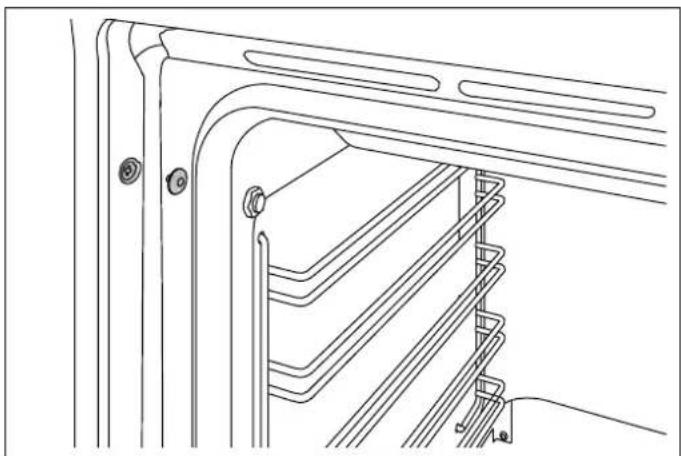
Technical line drawing of a mechanical assembly with multiple parallel channels and mounting holes (no text or symbols)Fig. 10
natural_image
Technical line drawing of a screwdriver inserted into a ladder inside a storage cabinet (no text or symbols)Fig. 11
natural_image
Technical line drawing of a cabinet or rack structure with no visible text or symbolsFig. 12
RACCORDEMENT ÉLECTRIQUE
REPLACEMENT DES COMPOSANTS
natural_image
Simple diagram with a rectangle and horizontal lines, no text or symbols presentHYDROCLEAN (FOUR À ONZE FONCTIONS UNIQUEMENT)
natural_image
Diagram of a refrigerator interior showing door, drawer, and drawer with directional arrows indicating movement (no text or symbols)Fig. 17
natural_image
Technical illustration of a mechanical assembly with two views: top shows a rectangular plate and bottom shows a multi-compartment tray (no text or symbols)natural_image
Technical line drawing of a mechanical assembly with an arrow indicating rotation (no text or symbols present)Fig. 19
Fig. 18
DIRECTIVES DE CUISSON
SONDE TEMPÉRATURE (SI DISPONIBLE)
natural_image
Technical line drawing of a door frame with a ladder and scroll, showing directional arrows indicating movement (no text or symbols)Fig. 24
natural_image
Technical line drawing of a door frame with a horizontal bar and two arrows indicating assembly or movement (no text or symbols)Fig. 23
RETRAIT DES GUIDES TÉLESCOPIQUES
natural_image
Technical line drawing of a mechanical assembly with a lever and guide mechanism (no text or symbols)NETTOYAGE DE L'APPAREIL
natural_image
Technical line drawing of a refrigerated storage unit with two arrows indicating flow direction (no text or symbols)Fig. 25
natural_image
Technical line drawing of a wall-mounted rack or panel with two upward arrows indicating top positions (no text or symbols present)Fig. 26
REMPLACEMENT DE L'AMPOULE DU FOUR
REMPLACEMENT DES JOINTS DU RÉSERVOIR

ATTENTION !
natural_image
Technical line drawing of a mechanical component with an inset showing a close-up view of a housing or mounting bracket (no text or symbols present)Fig. 28
natural_image
Technical line drawing showing two views of a mechanical component mounted on a panel (no text or symbols)Fig. 27
natural_image
Technical line drawing of a kitchen appliance interior showing front and side views (no text or symbols)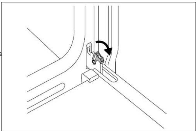
natural_image
Technical line drawing of a mechanical assembly with a lever and pivot point (no text or symbols)Fig. 30
text_image
n etFig. 31
natural_image
Technical line drawing of a door frame with arrows indicating direction (no text or symbols)Fig. 32
Fig. 29
natural_image
Technical line drawing of a mechanical assembly with an upward arrow indicating motion or force (no text or symbols present)Fig. 33
natural_image
Technical line drawing of a mechanical assembly with an upward arrow indicating motion (no text or symbols present)Fig. 34
LE FOUR NE FONCTIONNE PAS
© 2025 BERTAZZONI. All rights reserved.
3100987_v.01