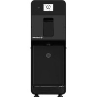
C111 - Ice machine Stoelting - Free user manual and instructions
Find the device manual for free C111 Stoelting in PDF.


User questions about C111 Stoelting
0 question about this device. Answer the ones you know or ask your own.
Ask a new question about this device
Download the instructions for your Ice machine in PDF format for free! Find your manual C111 - Stoelting and take your electronic device back in hand. On this page are published all the documents necessary for the use of your device. C111 by Stoelting.
USER MANUAL C111 Stoelting
1 SAFETY PRECAUTIONS
1 Before connecting the machine to the power source, check that the voltage shown on the rating plate matches your electricity supply. Connect the machine to a single-phase supply through a grounded outlet as required by current regulations.
2 Do not use extension cables to connect the machine.
3 To avoid any risks, if the power cable is damaged, it must be replaced by the manufacturer, by an authorized technician or by a similarly qualified person.
4 The machine is not suitable for outdoor use.
5 The machine must be installed in the upright position.
6 Before cleaning, always disconnect the machine by removing the plug from the outlet.
7 Always disconnect the machine before removing any of the panels for cleaning or maintenance work.
8 This machine must not be used by persons unless they have been trained regarding the safe use of the machine and understand the risks involved.
9 Only persons who know and have practical experience of the machine are permitted access to the inner components of the machine, especially when dealing with issues regarding safety and hygiene.
10 This machine is intended exclusively for domestic and similar use.
11 For the machine to operate correctly, ambient temperature must be between +41° and +89°F.
12 Use the machine to cool the indicated liquids only.
13 Do not introduce dangerous or toxic liquids to the machine.
2 TECHNICAL CHARACTERISTICS
C111-37
Hopper capacity, approx gal 1
Freezing Cylinder capacity, gal 0.5 approx
Dimensions:
width in 10.2
depth in 22.4
height in 28.7
Net weight, approx. lbs 106
Gross weight, approx. lbs 121
Hermetic compressor
Air-cooled condenser
Overload protector
Noise level less than 70 dB (A)

IMPORTANT
Electrical characteristics: read the data on the data plate of the machine; this data plate is located in the lower part of the front panel, behind the drip tray. The serial numbers of the machine (preceded by the symbol #) is indicated on the frame, at the rear of the machine, behind the condenser cover panel. Always refer to the data shown on the plate.
The manufacturer reserves the right to amend this manual without notice.
3 INTRODUCTION
Read this instruction booklet carefully in order to familiarize yourself with all aspects of the machine.
As with all mechanical products, this machine also requires cleaning and care. In addition, its correct operation may be compromised by possible errors made by the operator during the disassembly and cleaning operations. For this reason, it is important that the disassembly, cleaning, sanitizing and reassembly procedures - being everyday tasks - are familiar, without any room for error on the part of the machine user.
The warranty for the C111 is as follows: Five years on major components including: freezing cylinder, hopper, compressor and, drive motor; One year on non-wear parts and labor.

Every machine includes White Glove Service. One call does it all – customer service, technical service, parts or warranty information, installation, startup, sales, on-site service dispatch and much more. Available 24 hours a day, seven days a week year-round. Contact White Glove Service at 800-319-9549
4 UNPACK THE MACHINE
1 Take the machine out of its packaging, which we recommend you keep for future requirements.
2 Make sure that the machine has not been damaged during transportation. If this is the case, immediately make a claim with your carrier.
NOTICE: Do not lay the machine on its side or back.
NOTICE: Do not lift the machine by the tank, auger, or handles. Only lift by grasping the bottom of the machine.
NOTICE: The machine must sit in the upright position for 24 hours before turning it on. This will allow the oil in the compressor to settle into place following shipping.
3 Place the machine onto a counter designed to withstand its weight, including when full.
4 Leave a clearance of at least 6" around the whole machine to avoid obstructing the cooling air flow.
5 Check the stability of the device, adjusting the height of the legs if necessary. If the dispenser is provided with taller legs (approximately 4"), these must replace the original ones.

ATTENTION
Make sure the machine is properly grounded, otherwise you may cause electric shocks to persons or damage to the machine.
6 The machine does not leave the factory washed and sanitized. Before use, it must be disassembled, washed and sanitized, following the instructions in 6.4 CLEANING.

IMPORTANT
Position the machine in such a way that the power supply cable is easily accessible.
5 TO OPERATE SAFELY
1 Do not use the machine before reading this instruction manual first.
2 Do not use the machine unless it is properly grounded.
3 Do not operate the machine if the panels are not in place and secured with screws.
4 Do not insert your fingers in panel louvers or spigot outlet.
5 Do not remove parts or panels for cleaning or maintenance without first making sure the machine is disconnected from the electricity supply.
6 The cover must remain closed at all times.
6 OPERATING PROCEDURES

IMPORTANT
Before use, clean and sanitize the machine according to the instructions provided in 6.4 CLEANING.

IMPORTANT
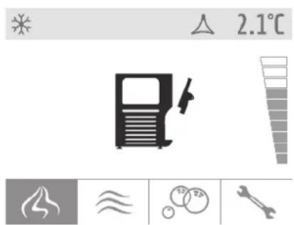
If the spigot assembly has not been installed, the machine cannot operate and the display shows the spigot assembly open icon (see figure 1).
text_image
2.1°Cfigure 1
This machine is equipped with a hopper designed to keep the mix refrigerated and a freezing cylinder for the production of the soft serve.
Every time soft serve is dispensed, the same quantity of soft serve mix feeds into the freezing cylinder from the hopper.
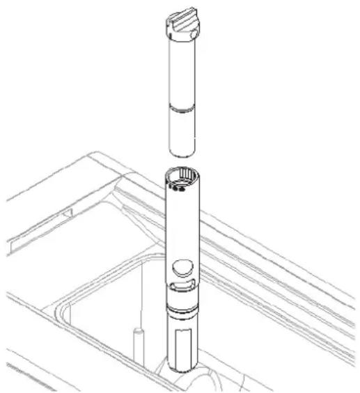
In order to obtain softer and lighter soft Serve, make sure that the carburetor is installed correctly. (see figure 2)
natural_image
Technical line drawing of a mechanical assembly with cylindrical components and mounting brackets (no text or symbols)figure 2
For best results, the following steps must be performed in the order specified:
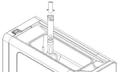
1 Insert the lower part of the carburetor into the mix inlet tube
ENGLISH C111
in the hopper, making sure it is fully seated. (see figure 3)
natural_image
Technical line drawing of a mechanical component with a cylindrical assembly and an arrow indicating direction (no text or symbols)figure 3
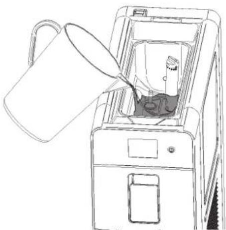
2 Pour mix into the hopper and wait for the freezing cylinder to fill. The cylinder is filled when no more air bubbles exit the holes in the carburetor. (see figure 4)
natural_image
Line drawing of a mechanical device with a bucket pouring liquid into a container (no text or symbols)figure 4
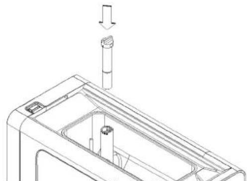
3 Insert the upper part of the carburetor into the lower one. (see figure 5)
natural_image
Technical line drawing of a mechanical component with a cylindrical part inserted, showing internal structure and a downward arrow indicating motion (no text or symbols)figure 5
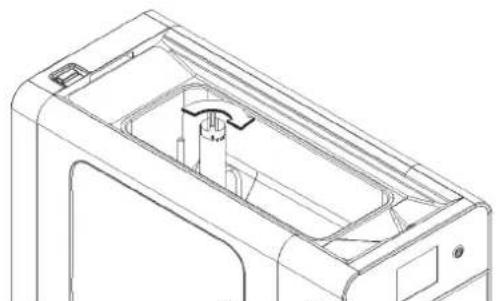
4 Turn the carburetor fully clockwise to stop the mix entering the cylinder. (see figure 6)
natural_image
Technical line drawing of a mechanical housing or enclosure with internal components (no text or symbols)figure 6
5 Install the hopper cover, turn the main power switch on, and start preparing soft serve. (See 6.1 DESCRIPTION OF CONTROLS)
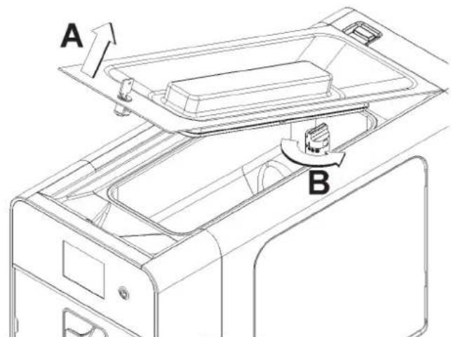
6 When the product is ready, remove the hopper cover and turn the upper part of the carburetor counterclockwise to allow the mix to enter the freezing cylinder.(see figure 7) The quantity of air in the soft serve can be adjusted, keeping in mind that, starting from the closing position:
complete rotation counterclockwise
: fully open, lower quantity of air in the soft serve (low overrun)
minimum rotation counterclockwise
only open slightly, greater quantity of air in the soft serve (high overrun)
text_image
A Bfigure 7
7 After making adjustments, install the hopper cover.

IMPORTANT
Use the machine with foodstuff only. Not intended for household use.
8 Dispense the soft serve using the spigot handle.
9 If the carburetor adjustments do not make the desired consistency, the mix can be modified as follows: Soft serve too soft : increase the amount of liquid (water or milk) from 5 % to 10 % of the total volume. Soft serve too hard : decrease the amount of liquid (water or milk) from 5 % to 10 % of the total volume.
10 The machine must operate continuously: the cooling system stops automatically when the product is ready to be dispensed. The auger speed decreases and only increases when dispensing. The cooling system and auger operate at default time intervals in order to restore the proper consistency to the product.
6.1 DESCRIPTION OF CONTROLS
The machine has a main power switch, an on/off button and a touch display. The following operating modes are available:
SOFT SERVE PRODUCTION: in this operating mode, the machine prepares soft serve.
NIGHT MODE: in this operating mode, the machine keeps the liquid mix at a suitable temperature to preserve it. This function is useful at night to keep the quality of the mix intact and limit electricity consumption.
WASHING: in this operating mode, cooling is disabled. This function is used during washing and sanitizing to prevent the solution used from being cooled and freezing.
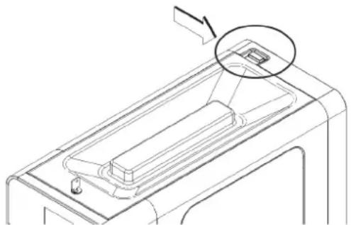
MAIN SWITCH
The main power switch is located on the top of the machine at the back.
natural_image
Technical line drawing of a mechanical component with an arrow pointing to a detail (no text or symbols present)Its function is as follows:
Position 0 : machine is off
Position I : machine enabled for operation but in Standby mode. Only indicator light Q is on.

IMPORTANT
If you turn the machine off and back on at the main power switch, it will restart in the same operating mode it was in when it was switched off.
ON/OFF BUTTON
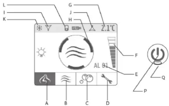
The ON/OFF button P is located to the right of the touch display. If indicator light Q comes on, the machine is switched on and in standby mode, ready for operation. Hold down the ON/OFF button for one second to turn the machine on and off.
TOUCH DISPLAY
text_image
L I K G J H 2.1°C F AL 01 E Q P A B C Dfigure 8
The following icons appear on the display:
A SOFT serve PRODUCTION icon; when pressed, the SOFT serve function is enabled.
B NIGHT MODE icon; when pressed, the NIGHT MODE function is enabled
C WASHING icon; when pressed, the WASHING function is enabled.
D PARAMETERS icon; when pressed, adjustments can be made to the operating PARAMETERS.
E Alarm code. Indicates an alarm and displays the relevant code.
F Consistency bar. Indicates the set consistency level.
G Mix temperature. Indicates the mix temperature in the hopper.
H Status icon. Indicates the machine status (soft serve, night mode, washing, alarm) and the soft serve preparation status when the soft serve mode is enabled: red icon: soft serve not ready yellow icon: soft serve almost ready green icon: soft serve ready
I Hopper cooling icon. Indicates that the hopper cooling is in operation.
J Freezing cylinder cooling icon. Indicates that the freezing cylinder cooling is in operation.
K Compressor icon. Indicates the compressor is in operation.
L Display shut-down icon. Indicates that the touch display has shut down and no controls can be accessed.
Turn the main power switch to position I. Red indicator light Q comes on.
Hold down button P until the machine starts up again. Select the desired function using icons A, B, c or D.
SOFT SERVE MODE
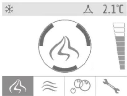
In this operating mode, the machine produces soft serve and the mix in the hopper is kept at a suitable temperature to preserve it. The soft serve preparation status is indicated on the display by the central icon and by the color of the arrows.(see figure 9)
text_image
2.1°Cfigure 9
When the soft serve is ready, the auger slows down, the cooling system stops and the machine switches to serve mode. At default intervals (factory set to every 10 minutes), the auger increases speed and the cooling system runs to restore the proper soft serve consistency.
When the spigot is opened, the auger speed increases and the cooling system runs.
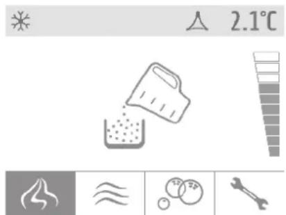
In order to produce soft serve, the hopper must contain a suitable quantity of mix. If the mix level gets low, the central icon displays low product.(see figure 10)
Consistency adjustment
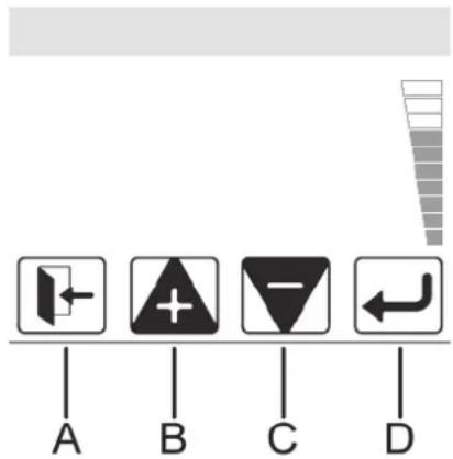
The consistency of the soft serve can be adjusted on a scale of 1 to 10. To adjust, touch the graduated bar on the right-hand side of the touch display. The following controls are available:
A Exit icon: Exits without making any changes.
B Decrease icon: Decreases the consistency value.
C Increase icon: Increases the consistency value.
D Confirm icon: Confirms the value set.
(see figure 11)
text_image
A B C Dfigure 11
NIGHT MODE
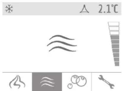
In this operating mode, the mix in both the hopper and in the freezing cylinder is kept at a food safe temperature (factory set to 36^ F) to preserve it. The display indicates the night mode icon. (see figure 12)
text_image
2.1°C ※ △figure 12
When the mix has reached the set temperature, the auger slows down, the cooling system stops, and the machine switches to standby mode. At default intervals (factory set to every 10 minutes), the auger increases speed and the cooling system starts to retain the proper temperature.

IMPORTANT
The product temperature during night mode is factory set to 36°F.
WASHING MODE
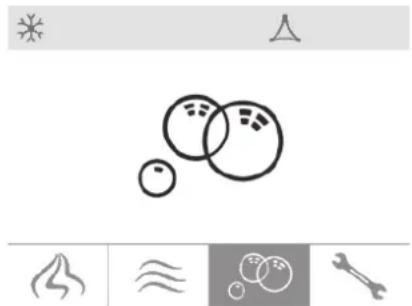
In this operating mode, the cooling system does not operate and the auger turns at a speed suitable for washing the machine. The display indicates the Washing icon. (see figure 13)
natural_image
Simple line drawing of a ball with bubbles and motion indicators below (no text or symbols)figure 13
ALARMS
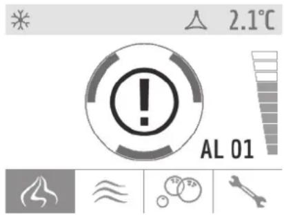
The machine is fitted with a self-diagnosis system. In the event of a breakdown, the user is notified by the alarm icon on the dis-
play. Press this icon to show the explanatory text relating to the alarm. (see figure 14)
text_image
2.1°C AL 01figure 14
MAINTENANCE ALARM (AL14)
After every 1500 hours of operation it is necessary to replace the auger seal. After replacing the seal, the AL14 alarm must be reset.
To reset the alarm 14 is necessary:
- press parameters icon
- type user password (0000)
- press on hourglass icon
- press RESET button
- type user password (0000)
- press exit button
The machine parameters are factory set to guarantee optimum operation. To prevent any risks of malfunctioning, the parameters must only be changed by the manufacturer, technical support, or other similarly qualified persons.
6.3 SUGGESTIONS
1 All machines of this kind emit heat. Should the heat generated be excessive, make sure that no heat sources are located near the machine and, specifically, near the louvered panels. Also make sure the air flow is not obstructed by the walls, boxes or other items. Leave a clearance of at least 6" all around the machine. Also make sure the filter situated behind the rear panel is clean.
2 This machine is only intended for use with confectionery products.
6.4 CLEANING
1 Cleaning and washing the machine are vital to guarantee perfect preservation of product flavor and maximum efficiency of your machine. The procedures described below must be considered of a general nature and may vary due to local health and safety regulations.
2 Before disassembling for washing, the machine must be emptied. Proceed as follows:
1 on the keypad, select the WASHING operating mode
2 if necessary, wait for the mix to liquify
3 place a bucket under the spigot and empty all the contents of the hopper and freezing cylinder
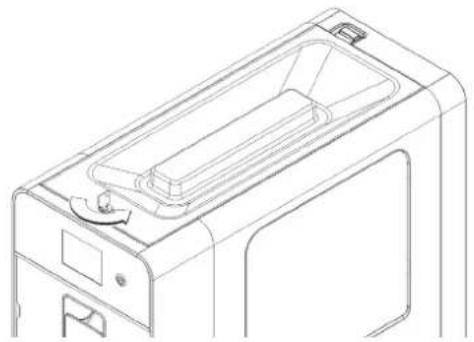
4 remove the hopper cover.
If the cover is fitted with a safety lock, turn the key counterclockwise. (see figure 15)
5 fill the hopper with water and allow the machine to operate in WASHING mode for a few minutes. Then empty the water out of the machine.
6 press and hold the ON/OFF button to turn off the machine
7 turn off the main power switch
6.4.1 DISASSEMBLY

ATTENTION
Before disassembling any component, always unplug the machine from the main power source.
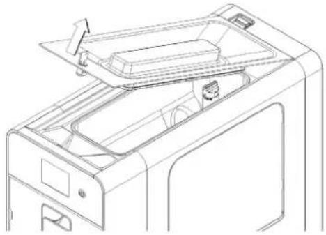
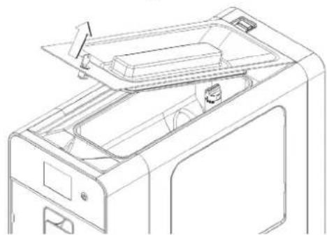
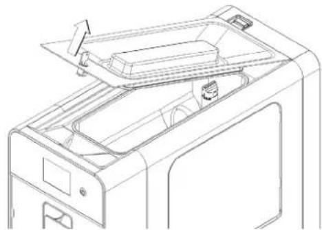
1 Remove the hopper cover. (see figure 16)
If the cover is fitted with a safety lock, turn the key counterclockwise. (see figure 15)
natural_image
Line drawing of a mechanical device casing with internal components and mounting holes (no text or symbols)figure 15
natural_image
Technical line drawing of a printer internal structure (no text or symbols)figure 16
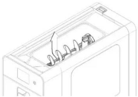
2 If present, remove the auger in the hopper. (see figure 17)
natural_image
Line drawing of a refrigerator interior showing internal components and a directional arrow (no text or symbols)figure 17
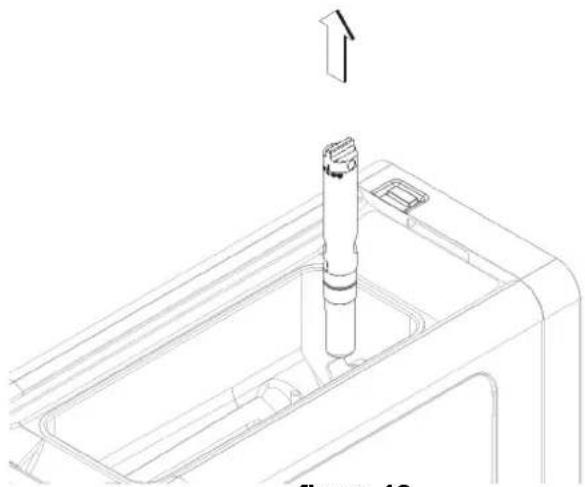
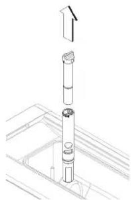
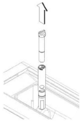
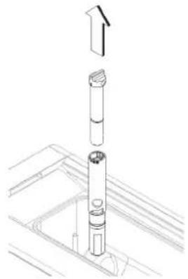
3 Remove the carburetor, both the upper part that the lower
part and disassemble it. (see figure 18) and (see figure 19).
natural_image
Technical line drawing of a mechanical component with an upward arrow indicating motion (no text or symbols)figure 18
natural_image
Technical line drawing of a mechanical assembly with an upward arrow indicating motion (no text or symbols)figure 19
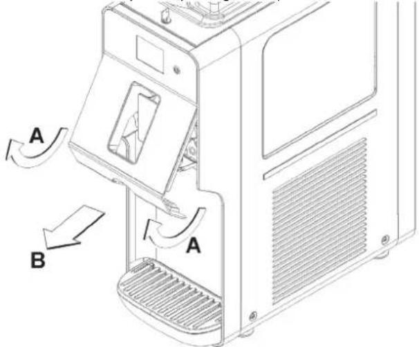
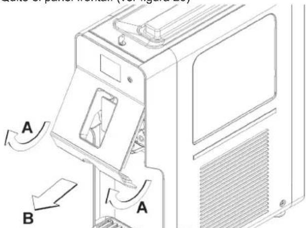
4 Remove the front panel. (see figure 20)
text_image
A B Afigure 20
5 Unscrew both knobs from the spigot assembly. (see figure
21)

natural_image
Technical line drawing of a mechanical device with gears and ventilation slots (no text or symbols)figure 21
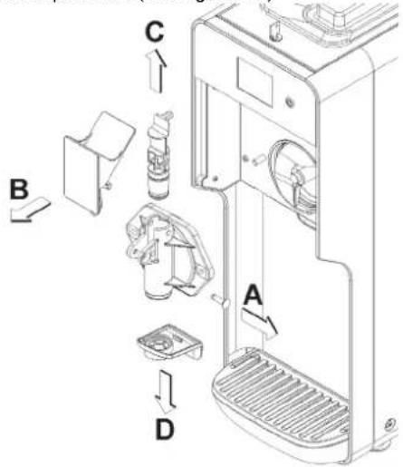
6 Remove the spigot assembly and disassemble it, following the sequence specified. (see figure 22)
text_image
Diagram of a refrigerator interior with labeled parts A, B, C, and D indicating different components.figure 22
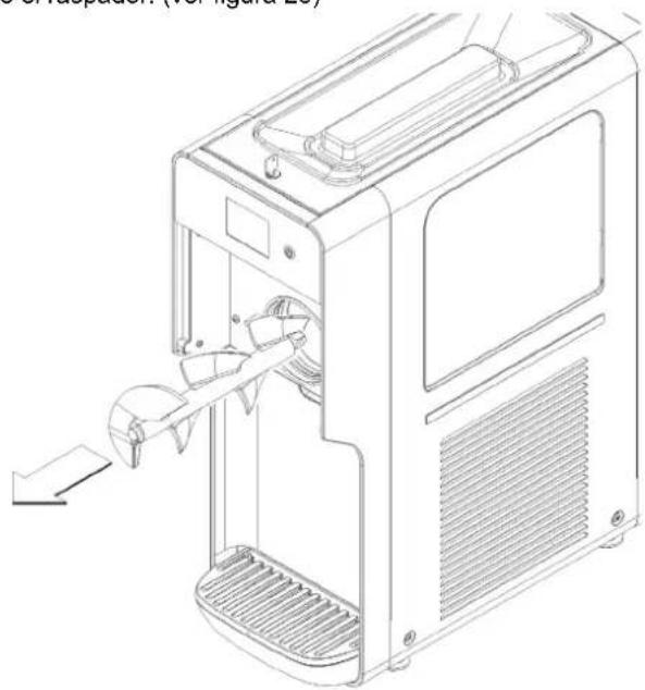
7 Remove the auger. (see figure 23)

natural_image
Line drawing of a computer monitor with an open door and scroll, showing internal components (no text or symbols)figure 23
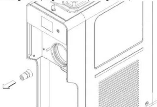
8 Remove the auger coupling and seal. (see figure 24)
natural_image
Technical line drawing of a mechanical device with no visible text or symbolsfigure 24
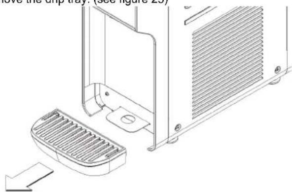
9 Remove the drip tray. (see figure 25)
natural_image
Technical line drawing of a refrigerator unit with grating and ventilation slots (no text or symbols)figure 25
6.4.2 WASHING

IMPORTANT
If the power supply cable is damaged, it must be replaced by the manufacturer or an authorized service provider to avoid all risk.

ATTENTION
Before any cleaning operation, always disconnect the dispenser from the power source.
1 Fill a bucket with approximately one gallon of 90-110 °F water) and 1 oz of mild detergent (Stera-Sheen green label), following the manufacturer's instructions. A solution that is too concentrated may damage the parts to be washed, whereas one that is too diluted may not clean properly. Do not use any abrasive detergents.

IMPORTANT
In order to avoid damaging the machine, only use detergents that are compatible with plastic components.
2 In order to avoid damaging the machine, only use detergents that are compatible with plastic components.

ATTENTION
When cleaning the machine, do not use excessive amounts of water around the electrical components. This could cause electric shocks or damage to the machine.
3 Wash the freezing cylinder, the hopper, and the mix inlet tube using the brush supplied with the unit.
4 Rinse all washed parts under running water.
6.4.3 SANITIZING
Sanitizing must be done immediately before starting up the dispenser. Do not allow the dispenser to remain idle for a long time after sanitation.
1 Before starting the procedures described below, wash your hands with antibacterial soap.
2 Prepare 2 gallons of Stera-Sheen sanitizing solution according to the manufacturer's instructions.
3 Immerse all parts to be sanitized in the solution for the time indicated by the product manufacturer.
4 Allow the sanitized parts to air dry on a clean surface.
5 Dry the external parts of the dispenser without using abrasive cloths.
6.4.4 ASSEMBLY
NOTE: Total Blend sanitary lubricant, or equivalent must be used when lubrication of parts is specified. Total Blend can be used to lubricate parts and also as a spline lubricant. Do not use more than one packet of Total Blend per freezing cylinder.
NOTE: The United States Department of Agriculture and the Food and Drug Administration require that lubricants used on food processing equipment be certified for this use. Use lubricants only in accordance with the manufacturer's instructions.
1 Install the drip tray.

IMPORTANT
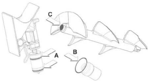
Lubricate the spigot piston, the auger seal and the front of the auger in the points indicated in figure using only Total Blend or other food grade sanitary lubricant.
text_image
Technical diagram of a mechanical device with labeled parts A, B, and C2 Install the auger coupling onto the auger and insert it into the freezing cylinder. Rotate the auger so that the coupling engages the drive shaft.
3 Assemble the spigot assembly by first inserting the spigot piston into the front door. Then install the handle onto the door and secure it with the pin. Refer to Figure 20.
4 Place the front door assembly onto the studs and secure with the knobs, tightening them carefully.
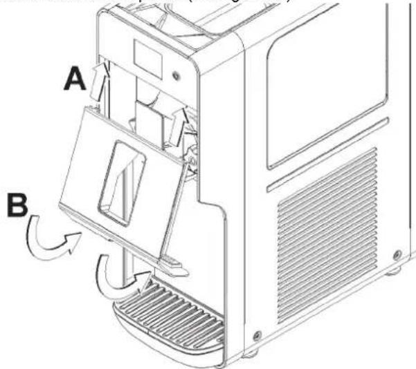
5 Reassemble the front panel. (see figure 26)
text_image
A Bfigure 26
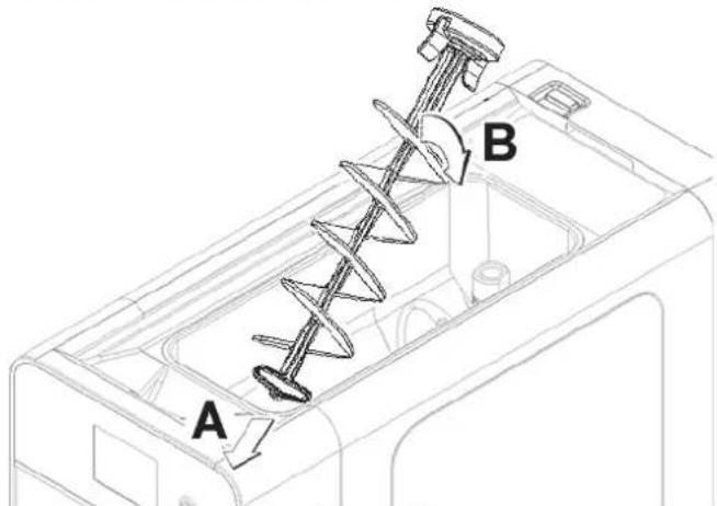
6 Assemble the hopper auger taking care to insert the ends in the grooves in the hopper.(see figure 27)
text_image
A Bfigure 27
6.4.5 IN-PLACE SANITIZATION
The sanitizing of the assembled machine prior to operation should be performed in addition to the sanitizing of the disassembled machine described herein above, and never instead of it.
1 Prepare 2 gallons of sanitizing solution according to the manufacturer's instructions (Stera-Sheen green label).
2 Pour the solution into the hopper.
3 Using a suitable brush, wipe the solution onto all the parts above the level of the solution including the underside of the hopper cover.
4 Install the cover and operate the machine for approximately 5 minutes.
5 Drain the sanitizing solution from the bowls through the spigots and then dispose of it.
6 Place a container under the spigot and rinse the machine with mix to flush out any remaining sanitizing solution.
7 MAINTENANCE
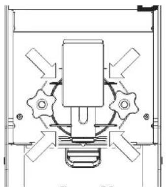
1 Every day: check the machine and make sure there are no leaks from the spigot assembly seal. If you notice a leak, first check that the components have been assembled correctly, then make sure the seal is not worn or damaged, in which case replace it with an original spare part from the manufacturer.
ENGLISH C111
(see figure 28)
natural_image
Technical diagram of a mechanical assembly with gears and directional arrows (no text or labels)figure 28
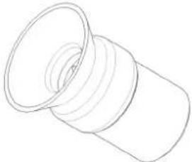
2 Every week: make sure the auger seal is not worn or damaged. If it is, replace with an original spare part from the manufacturer. (see figure 29)
natural_image
Simple line drawing of a cylindrical object with a flanged top and bottom (no text or symbols)figure 29
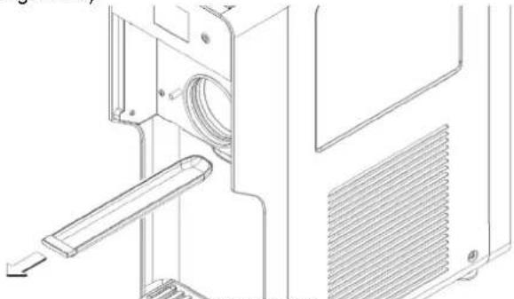
3 Every week: check for auger seal leaks by examining the drain tray (see figure 30). In case of a leak, make sure the auger seal is properly installed and not worn or damaged. If it is, replace with an original spare part from the manufacturer (see figure 29).
natural_image
Technical line drawing of a mechanical device with internal components and mounting bracket (no text or symbols)figure 30
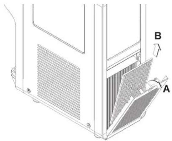
4 Every Month: eliminate any dust that has built up on the condenser filter situated at the back of the machine. (see figure
31)
natural_image
Technical line drawing of a computer tower with ventilation grilles and labeled parts A and B (no text or symbols beyond labels)figure 31

ATTENTION
Be careful with the condenser fins as they are sharp.
5 In case of strange noise or failure, disconnect the machine from the power source and call for service.
natural_image
Technical line drawing of a mechanical assembly with cylindrical components and mounting brackets (no text or symbols)figura 2
natural_image
Technical line drawing of a mechanical device interior with a cylindrical component and mounting bracket (no text or symbols)figura 3
natural_image
Line drawing of a 3D printer with a bucket pouring liquid into the cover (no text or symbols)figura 4
natural_image
Technical line drawing of a mechanical component with a cylindrical pin inserted (no text or symbols)figura 5
natural_image
Technical line drawing of a mechanical component with internal structure (no text or symbols)figura 6
natural_image
Technical line drawing of a mechanical component with a magnified inset showing a small component (no text or symbols)text_image
L I K G J H 2.1°C F AL 01 E Q P A B C Dfigura 8
text_image
2.1°C * △ 2.1°C Fire Wet Oscillator Candle Machineryfigura 10
natural_image
Simple line drawing of a ball with motion lines and icons below (no text or symbols)figura 13
ALARMAS
text_image
2.1°C AL 01figura 14
natural_image
Technical line drawing of a mechanical device casing with internal compartments and mounting bracket (no text or symbols)figura 15
natural_image
Line drawing of a printer internal structure with no visible text or symbolsfigura 16
natural_image
Line drawing of a microwave oven with internal cooling fan and cooling tower (no text or symbols)figura 17
natural_image
Technical line drawing of a mechanical component with an upward arrow indicating motion (no text or symbols)figura 18
natural_image
Technical line drawing of a mechanical assembly with an upward arrow indicating motion (no text or symbols)figura 19
5 Quite el panel frontal. (ver figura 20)
text_image
Technical diagram of a computer tower with labeled components A and B, showing internal structure and directional arrows.natural_image
Technical line drawing of a computer device showing internal components and ventilation slots (no text or symbols)figura 21
text_image
Diagram of a refrigerator interior with labeled parts A, B, C, and D indicating different components.figura 22
8 Quite el raspador. (ver figura 23)
natural_image
Line drawing of a desktop computer with a scroll wheel and ventilation slots (no text or symbols)figura 23
natural_image
Technical line drawing of a mechanical device with ports and a scroll wheel (no text or symbols)figura 24
natural_image
Technical line drawing of a dual-chamber refrigerator with ventilation slots and a gridded base (no text or symbols)figura 25
7.4.2 LAVADO

IMPORTANTE
text_image
Technical diagram of a mechanical device with labeled parts A, B, and Cnatural_image
Technical line drawing of a mechanical assembly with gears and housing (no text or symbols)figura 28
natural_image
Simple line drawing of a cylindrical object with a looped top surface (no text or symbols)figura 29
natural_image
Line drawing of a computer oven with ventilation slots and a handle (no text or symbols)figura 30
natural_image
Technical line drawing of a computer tower with ventilation grilles and labeled parts A and B (no text or symbols beyond labels)figura 31

ATTENCION
natural_image
Technical line drawing of a mechanical assembly with cylindrical components and a base (no text or symbols)figure 2
natural_image
Technical line drawing of a mechanical device interior with a cylindrical component inserted (no text or symbols)figure 3
natural_image
Line drawing of a device with a pitcher pouring liquid into a container (no text or symbols)figure 4
natural_image
Technical line drawing of a device casing with internal components and a downward arrow indicating motion (no text or symbols)figure 5
natural_image
Technical line drawing of a mechanical device casing with internal components (no text or symbols)figure 6
natural_image
Technical line drawing of a mechanical component with a highlighted section (no text or symbols)text_image
L I K G J H 2.1°C F AL 01 E P Q A B C Dfigure 8
natural_image
Simple line drawing of three overlapping circles with abstract shapes below (no text or symbols)figure 13
ALARMES
text_image
2.1°C AL 01figure 14
ENTRETIEN ALARM (AL 14)
natural_image
Technical line drawing of a mechanical device casing with internal components (no text or symbols)figure 15
natural_image
Technical line drawing of a printer internal structure (no text or symbols)figure 16
natural_image
Line drawing of a microwave oven with internal cooling fins and a paper airplane inside (no text or symbols)figure 17
natural_image
Technical line drawing of a mechanical component with a cylindrical shaft inserted into a housing (no text or symbols)figure 18
natural_image
Technical line drawing of a mechanical assembly with an upward arrow indicating motion (no text or symbols)figure 19
natural_image
Line drawing of a mechanical device with ventilation slots and a lid (no text or symbols)figure 21
text_image
Technical diagram of a refrigerator interior with labeled parts A, B, C, D and internal componentsfigure 22
natural_image
Line drawing of a desktop computer with an open door and scroll, showing internal components without any text or symbols.figure 23
natural_image
Technical line drawing of a mechanical device with internal components and ventilation slots (no text or symbols)natural_image
Line drawing of a mechanical device with cooling fan and ventilation slots (no text or symbols)figure 25
7.4.2 LAVAGE

IMPORTANT
text_image
Technical diagram of a mechanical device with labeled parts A, B, and C, showing exploded view and assembly.natural_image
Technical line drawing of a computer case with labeled components A and B, showing internal structure and airflow direction (no text or symbols beyond labels)figure 26
natural_image
Technical line drawing of a mechanical assembly with gears and directional arrows (no text or symbols)figure 28
natural_image
Simple line drawing of a cylindrical object with a flanged top and bottom (no text or symbols)figure 29
natural_image
Line drawing of a mechanical device with internal components and a handle (no text or symbols)figure 30
natural_image
Technical line drawing of a computer case with labeled components A and B (no text or symbols beyond labels)figure 31

ATTENTION
Stoelting, A Vollrath Company (“Stoelting”) warrants to the first user (the “Buyer”) that the Stoelting-branded freezer equipment (the “Equipment”) will be free from defects in materials and workmanship under normal use and proper maintenance for the period listed below in the Warranty Period section. All warranty periods begin on the date of original install or one (1) year from the shipping date, whichever occurs first. This warranty is subject to all conditions, exceptions, and limitations contained herein.
2. Disclaimer of Other Warranties:
THIS WARRANTY IS EXCLUSIVE; AND STOELTING HEREBY DISCLAIMS ANY IMPLIED WARRANTY OF MERCHANTABILITY OR FITNESS FOR PARTICULAR PURPOSE.
3. Remedies:
Stoelting's sole obligations, and Buyer's sole remedies, for any breach of this warranty shall be, at Stoelting's option, one of the following: repair or replacement of the affected component at Stoelting's plant in Kiel, Wisconsin, or refund of the purchase price of the affected Equipment. Stoelting, through an Authorized Stoelting Provider, will deinstall/reinstall the affected component from/into the equipment ("Labor") for the period listed below in the Warranty Period section. These obligations/remedies are subject to the conditions that Buyer (a) signs and returns to Stoelting, upon installation, the Start-Up and Training Checklist for the affected equipment, (b) gives Stoelting prompt written notice of any claimed breach of warranty within the applicable warranty period, and (c) delivers the affected equipment to Stoelting or its designated service location, in its original packaging/crating, also within that period. Buyer shall bear the cost and risk of shipping to and from Stoelting's plant or designated service location.
4. Warranty Period:
| Equipment | Part | Part Warranty Period Labor Warrant | y Period |
| Soft Serve & Shake Fire | Freezing Cylinders | Months | |
| Hoppers | |||
| Compressors | |||
| Drive Motors | |||
| Speed Reducers | |||
| Augers | |||
| Frozen Uncarbonated Beverage | Evaporator | Five (5) Years Twelve (12) Months | |
| Compressors | |||
| Drive Motors | |||
| Speed Reducers | |||
| Custard & Batch Two | Freezing Cylinders | Months | |
| Hoppers | |||
| Compressors | |||
| Drive Motors Twelve (12) Months | |||
| Speed Reducers | |||
| Beaters | |||
| Auger Shafts | |||
| Dipping Cabinets & Display Cabinets | All components Twelve (12) Months Twelve (12) Months | ||
| Frozen Beverage / Granita Dispenser | Compressors | Five (5) Years | Twelve (12) Months |
| Electronic Board | Three (3) Years | ||
| All other components | Two (2) Years | ||
| AutoVend | All components | Twelve (12) Months Twelve (12) Months | |
| Crème Whippers Two | Compressors | Months | |
| M20 Years Twelve (12) Months | |||
| Condensers | |||
| All equipment | All other components not specified above | Twelve (12) Months Twelve (12) Months | |
5. Conditions:
a) If the date of the original installation cannot be verified, these warranty periods begin one (1) year from the shipping date. It is the responsibility of the seller to disclose this information to the customer at the time of sale.
b) Stoelting shall not be responsible to provide any remedy under this warranty with respect to any component that fails by reason of negligence, abnormal use, misuse or abuse, faulty repair made by others, use with parts or equipment not manufactured or supplied by Stoelting, any modification or alteration of any parts or equipment, or damage in transit.
c) This warranty is valid only if the Equipment is installed and serviced by an Authorized Stoelting Provider and only if new, genuine Stoelting parts are used.
d) The Equipment installation location must have suitable conditions as explained in the Stoelting operators manual, specification sheet, and/or technical manual including but not limited to, ambient temperature, water supply parameters, and space requirements.
e) The Authorized Stoelting Provider must return defective parts, at Stoelting's discretion, for credit.
f) Any refrigerant other than that specified on the Equipment model identification nameplate voids this warranty.
6. Exceptions:
This warranty does NOT cover any of the following
a) Costs associated with installation labor, disposal of equipment being replaced, and shipping costs of replacement parts or Equipment.
b) Cleaning, maintenance or lubrication of the Equipment as outlined in the Stoelting operators manual.
c) This warranty does not extend to parts, sometimes called "wear parts", which are generally expected to deteriorate and to require replacement as equipment is used, including but limited to o-rings, auger flights, auger seals, auger support bushings, and drive belts. All such parts are sold AS IS.
d) External components including but not limited to hoses, piping, or electrical equipment.
e) Labor charges due to return trips or waiting if the Authorized Stoelting Provider is prevented from promptly starting service work upon arrival. This exception includes labor charges incurred for limited access facilities including, but not limited to, government and military buildings, and airports.
f) Failure, damage, or repairs due to faulty installation, misapplication, abuse, lack of service, or improper service, unauthorized alteration, improper operation as indicated in the Stoelting operators manual, including but not limited to failure to properly assemble and/or clean, improper tool usage, or use of unapproved lubrication, or cleaning and sanitizing supplies.
g) Any costs associated with electricity, including utility increases, from any reason whatsoever.
h) Damage resulting from the use of refrigerant other than that specified on the Equipment model identification nameplate.
i) The use of this equipment as a rental asset negates all warranties associated with the equipment.
j) Any special, indirect or consequential property or commercial damage of any nature whatsoever, if the jurisdiction allows this exclusion.
7. Limitations:
THE REMEDIES SET FORTH IN THIS WARRANTY SHALL BE THE SOLE LIABILITY STOELTING AND THE EXCLUSIVE REMEDY OF BUYER WITH RESPECT TO EQUIPMENT SUPPLIED BY STOELTING; AND IN NO EVENT SHALL STOELTING BE LIABLE FOR ANY INCIDENTAL OR CONSEQUENTIAL DAMAGES, INCLUDING AS EXAMPLES BUT NOT INTENDED TO BE LIMITED TO DOWNTIME, OVERHEAD, MATERIALS, PERFORMANCE PENALTIES, LOST SALES, LOST PROFITS, PRODUCT LOSS, OR PROPERTY DAMAGES, WHETHER FOR BREACH OF WARRANTY OR OTHER CONTRACT BREACH, NEGLIGENCE OR OTHER TORT, OR ON ANY STRICT LIABILITY THEORY.