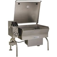
SGL-40-T1 - Saucepan Cleveland - Free user manual and instructions
Find the device manual for free SGL-40-T1 Cleveland in PDF.


| Product Type | Tilting Skillet |
| Brand | Cleveland |
| Model | SGL-40-T1 |
| Capacity | 40 gallons (approx. 151 liters) |
| Gas Supply | Natural gas or propane (per nameplate) |
| Electrical Supply | 115 V AC (standard), 208/240 V AC (optional) |
| Electrical Power | Minimum 10 amps (115 V) |
| Tilting Options | Manual (crank) or electric (switch) |
| Main Material | Stainless steel |
| Dimensions | See clearances: right 4" (manual) or 1" (electric), left 0, rear 0 |
| Approximate Weight | 250 lb (113 kg) estimated |
| Cooking Temperature | Adjustable via thermostat (low or high intensity) |
| Gas Safety | Automatic shut-off if tilt > 8°; relief valve to be inspected every 6 months |
| Electrical Safety | Grounding required; built-in circuit breaker |
| Cleaning | Hot water + mild detergent; nylon brush; avoid chlorine, steel wool, high pressure jet |
| Annual Maintenance | Inspection by qualified technician; lubrication of trunnions twice a year |
| Spare Parts (Gaskets) | Sides: SK2472402; Front 40 gal: SK2472401 |
| Repairability | Parts available; wiring diagram provided |
| Documentation | PDF manual 43 pages available online |
Frequently Asked Questions - SGL-40-T1 Cleveland
User questions about SGL-40-T1 Cleveland
0 question about this device. Answer the ones you know or ask your own.
Ask a new question about this device
Download the instructions for your Saucepan in PDF format for free! Find your manual SGL-40-T1 - Cleveland and take your electronic device back in hand. On this page are published all the documents necessary for the use of your device. SGL-40-T1 by Cleveland.
USER MANUAL SGL-40-T1 Cleveland
1333 East 179th St., Cleveland, Ohio, U.S.A. 44110
Ph: 216.481.4900 Fx: 216.481.3782
www.clevelandrange.com
FOR THE USER
FOR YOUR SAFETY
Do not store or use gasoline any other flammable liquids and vapours in the vicinity this or any other appliance.
WARNING: Improper installation, adjustment, or alteration, service or maintenance can cause property damage, injury or death. Read the installation and operating instructions thoroughly before installing or servicing this equipment.
IMPORTANT: Post in a prominent location, instructions to be followed in the event the user smells gas. This information shall be obtained by consulting your local gas supplier.
The following points are to insure the safe installation and operation of this equipment:
- Insure all gas and electrical supplies match rating plate and electrical stickers.
- Keep appliance area free and clear from combustibles.
- Observe all clearance requirements.
- All service must be performed by a qualified Cleveland Range Technician.
- Do not obstruct the flow of combustion and ventilation air.
NOTICE: When this appliance is installed with casters, it must be installed with the casters supplied, a connector complying with either ANSI Z21.69 • CSA 6.16 and a quick disconnect device complying with ANSI Z21.41 • CSA 6.9. It must also be installed with restraining means to guard against transmission of strain to the connector, as specified in the appliance manufacturer's instructions.
RETAIN THIS MANUAL FOR YOUR REFERENCE
POUR L'UTILISATEUR
POUR VOTRE SÉCURITÉ
Product Bulletin Cleveland Range Ltd
Caster Kit (CS-T1) for Skillet model T1
WARNING
For use only on a Cleveland Range Skillet model T1.
DO NOT attempt to use these parts on any other product. Failure to do so can cause property damage, Injury or death.
Read instructions thoroughly. Failure to do so can cause property damage, Injury or death.
This kit should be installed only by a Qualified Service Technician.
Parts Included
| Item Part Number Description Qty. | |
| 82 KE53046-1 Caster sleeve 4 | |
| 80 KE53068-3 Caster 2 | |
| 81 KE53068-4 Caster c/w brake 2 | |
| KE55407 Warning Label 1 | |
| KE603957 Instruction sheet, Caster T1 1 | |
| KE003646 Strap 1 |
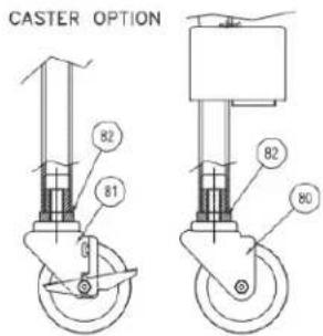
Installation Instructions
-
Disconnect electrical and or gas supplies.
-
Move unit to a location with space around it to work.
-
Jack up one end of the unit
-
Remove the feet by unscrewing.
-
Screw in the caster sleeves.
-
Screw in the Casters. Brake on front, no brake on rear.
-
Lower Skillet.
-
Repeat for other side.
-
Add Warning Label to rear leg support channel as shown.
-
Add restraint cable to unit as shown.
-
Fasten other end of restraint cable
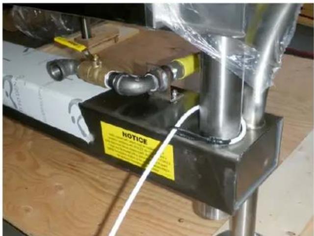
to guard against transmission of strain to the gas connector or electrical connection.
-
For gas units install gas connections using a connector complying with ANSI Z21.69 * CGA6.16 and a quick disconnect device complying with ANSI Z21.41 * CGA6.9.
-
When properly installed the strain relief will become tight and stop movement of the unit before strain is put on gas plumbing or electrical connection.
To complete installation connect unit, check for gas leaks, test unit functions.
INSTALLATION
INSPECTION
- Before unpacking visually inspect the unit for evidence. This unit must be installed in accordance with the of damage during shipping. clearances shown on the rating label which is adhered to
- If damage is noticed, do not unpack the unit, follow the unit, shipping damage instructions.
- Carefully remove unit from shipping carton. Remove any packing material from unit. After carefully unpacking check for "concealed" damage. If damage noticed, follow "SHIPPING DAMAGE INSTRUCTIONS" shown below.
- A protective material has been applied to the stainless
This unit must be installed in accordance with the clearances shown on the rating label which is adhered to
the unit.
RIGHT LEFT REAR
Manual Tilt 4" 0 0*
Power Tilt 1" 0 0*
*Allow 3.5" at rear for combustable walls.
steel panels. This material must be removed immediately after installation, as heat will melt the material and make it more difficult to remove.
CLEARANCE REQUIREMENTS
FOR YOUR SAFETY. Keep the appliance area free and clear of combustible materials.
SHIPPING DAMAGE INSTRUCTIONS
If shipping damage to the unit is discovered or suspected, observe the following guidelines in preparing a shipping 2. damage claim.
- Write down a description of the damage or the reason for suspecting damage as soon as it is discovered. This will help in filling out the claim forms later. 3.
- As soon as damage is discovered or suspected, notify the carrier that delivered the shipment.
- Arrange for the carrier's representative to examine the damage.
- Fill out all carrier claims forms and have the examini carrier sign and date each form.
GENERAL
Installation of the kettle must be accomplished by qualif installation personnel working to all applicable local and national codes. Improper installation of product could cause injury or damage.
This equipment is built to comply with applicable standa for manufacturers. Included among those approval agencies are: UL, A.G.A., NSF, ASME/N.Bd., CSA, CGA, ETL, and others. Many local codes exist, and it is the responsibility of the owner/installer to comply with these codes.
Observe all clearance requirements to provide proper make-up air flow. Do not obstruct the flow of combustic and ventilation air. Check rating plate to ensure that ke has been equipped to operate with the type of gas available at the installation.
Dimensions and clearance requirements are shown on the Specification Sheet.
INSTALLATION
- Position the unit in it's permanent location, and level the ed, unit by turning the adjustable feet.
- Once positioned and leveled, permanently secure the unit's flanged feet to the floor using 5/16" lag bolts and floor anchors (supplied by the installer). Three bolts are required to secure each of the flanged feet.
- Seal joints of flanged feet with a silicone sealant.
GAS
ENSURE THE GAS SUPPLY MATCHES THE KETTLE'S REQUIREMENTS AS STATED ON THE RATING PLATE.
Installation must conform, with local codes or in the absence of local codes, with the National Fuel Gas Code ANSI Z223.1/NFPA 54, or the Natural Gas and Propane Installation Code, CSA B149.1.
The appliance and its individual shut-off valve must be disconnected from the gas supply piping system during any pressure testing of that system at test pressures in excess of 1/2 psi (3.45 kPa).
The appliance must be isolated from the gas supply piping system by closing its individual manual shut-off valve during any pressure testing of the gas supply piping system at test pressures equal to or less than 1/2 psi (3.45 kPa).
It is recommended that a sediment trap (drip leg) be installed in the gas supply line. If the gas pressure exceeds 14" water column, a pressure regulator must be installed, to provide a maximum of 14" water column gas pressure to the gas control valve.
Connect the gas line to the manual valve located at the rear of the control box.
Use a gas pipe joint compound which is resistant to L.P. gas. Test all pipe joints for leaks with soap and water solution. Ensure that the gas pressure regulator is set for the manifold pressure indicated on the gas rating plate.
ELECTRICAL
NOTE: Wiring diagram is located on the underside of unit's control panel.
ENSURETHEELECTRICALSUPPLYMATCHESTHE UNIT'SREQUIREMENTSASSTATEDONTHERATING LABEL.
INSTALLATION CHECKS
Although the unit has been thoroughly tested before leaving the factory, the installer is responsible for ensuring the proper operation of unit once installed.
DO NOT ATTEMPT TO OPERATE THIS UNIT DURING A POWER FAILURE.
A cord and plug are supplied with the 115 volt unit. SHIP PLUG THE UNIT INTO ANY GUARDED OUTLET RATED FOR A MINING COMBUSTIBLES.
of 10 amps. The wiring diagram is located on the back of the console access panel.
When a unit is ordered and built for 208/240 volt, the line must be connected to the wiring terminations location inside the console. A wiring diagram is attached to the underside of the control panel.
WARNING: Electrical Grounding Instructions.
-
Supply power to the unit by placing the fused disconnect switch to the "ON" position.
-
Supply Turn on main gas supply to unit. Open the unit's shut-off valve (located at lower rear left).
-
Toggle HI / OFF / LO Switch to the "HI" or "LO" position.
-
For your safety the unit is equipped with a power interrupter which automatically shuts off the gas supply to the burners whenever the unit is raised more than 8^ .
This unit is equipped with a three-prong (grounding) plug for your protection against shock hazard and should be plugged directly into a properly grounded three-prong receptacle. Do not cut or remove the grounding prong this plug.
IMPORTANT: Before commencing to cook, ensure the pan is in the lowered position. Also ensure the cover is raised.
- Turn temperature control to maximum. Tilt pan until heat indicator light turns off and heating system shuts down. The pan should be on a 5-10° angle.
Standard supply voltage is 115 volts A.C., however, opt A.C. voltages can be supplied on special order. A sep fused disconnect switch must be supplied and installed the high voltage electrical supply line. The unit when installed, must be electrically installed and grounded in accordance with local codes, or in the absence of local codes, with National Electrical Code, ANSI/NFPA 70-1990 (USA) or the Canadian Electrical Code, CSA C22.2, Par (Canada).
-
Lower pan. Heat indicator light will re-light and heating system will re-energize.
-
Unit will continue to heat, heat indicator light will remain on until temperature is reached. Then the heat indicator light will cycle OFF indicating the heating system has 1 shut off. The heat indicator light will continue to cycle ON and OFF as the heating system cycles ON and OFF maintaining the desired temperature.
-
Toggle HI / OFF / LO Switch to the "OFF" position.
VENTILATION
Gas fired units are only to be installed under a ventilation
hood in a room which has provisions for adequate ma
air. Further information can be obtained by referring to U.S.A. National Fire Protection Associations NFPA96
regulations. These standards have also been adopted by the National Building Code in Canada..
CLEANING
After installation the unit must be thoroughly cleaned and sanitized prior to cooking.
WATER CONNECTION
(OPTIONAL)
A 1/2" NPT cold water line and/or a 1/2" NPT hot water line are required if unit is equipped with a single or double pantry faucet.
OPERATING INSTRUCTIONS
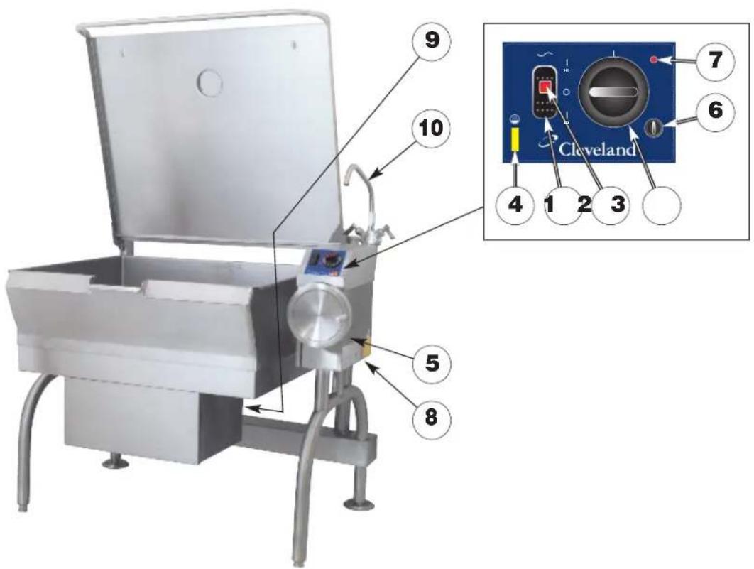
ITEM # DESCRIPTION
- HI / OFF / LO Switch
- Power Indicator Light (red)
- Temperature Dial
- Heat Indicator Light (yellow)
- Hand Tilt Wheel
- Power Tilt Switch (location may vary)
- Reset Button (location may vary)
- Manual Tilt Override
- Gas Shut Off Valve
- Faucet
- Tangent Draw-Off Valve
OPERATING THE UNIT
- Ensure the gas and electrical supply to the unit are in the ON position.
FOR YOUR SAFETY:
This unit will automatically shut off the gas supply when pan is raised more than 8°.
Before commencing to cook, ensure pan is in the lowered position.
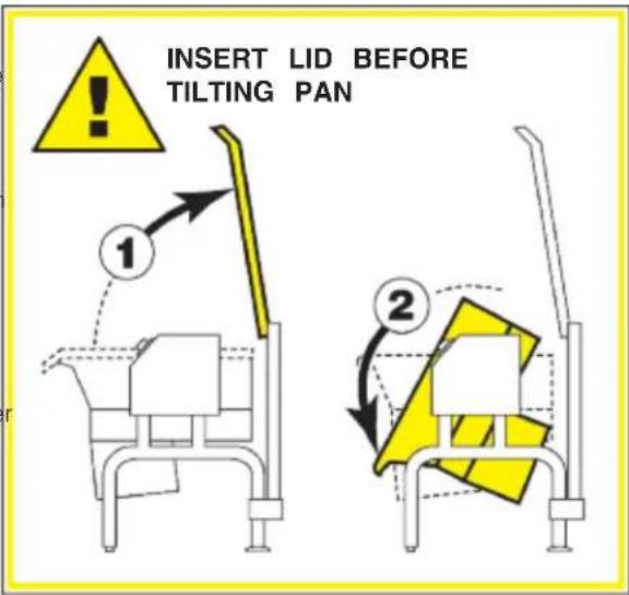
- MANUAL TILT: Cleveland braising pans are equipped with a manual tilt mechanism for raising and lowering the pan. To raise pan, raise the cover and turn the crank clockwise. To lower pan, turn counterclockwise.
POWER TILT: Cleveland braising pans can also be equipped with an optional electric power tilt mechanism for raising and lowering the pan. To raise pan, raise the cover and press up on the tilt switch. To lower pan, press down on the tilt switch,
- Toggle HI / OFF / LO Switch to the "HI" or "LO" position. The red Power Indicator Light indicates power is on. The yellow Heat Indicator Light indicates burners are on.
- To preheat, set Temperature Dial to desired cooking temperature. Unit is preheated when the yellow light goes out.
- Insert product in pan.
- If desired, once product has cooked, it can be held prior to serving at a lower temperature setting.
- When cooking is completed, set Temperature Dial and HI / OFF / LO Switch to the OFF position.
- The best time to clean the unit is immediately after use, once unit has cooled down. Refer to section titled "CLEANING INSTRUCTIONS" for details.
OPERATING SUGGESTIONS
- Turn power switch to the "OFF" position when unit is not in use.
- Allow unit to preheat before adding product.
- Always lift the spring assist cover before activating the tilt mechanism.
- During an electrical power interruption, turn Power Switch to the OFF position. This unit cannot be made to operate without electrical power.
CLEANING INSTRUCTIONS

CAUTION
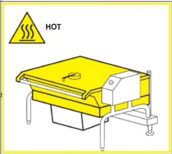
SURFACES MAY BE EXTREMELY HOT!
CARE AND CLEANING
Cooking equipment must be cleaned regularly to maintain its fast, efficient cooking performance and to ensure its continued safe, reliable operation. The best time to clean is shortly after each use (allow unit to cool to a safe temperature).
WARNINGS

Chloride Cleaners
Do not use detergents or cleansers that are chloride based or contain quaternary salt.

Wire Brush & Scrapers
Do not use a metal bristle brush or scraper.

Steel Pads
Steel wool should never be used for cleaning the stainless steel.
High Pressure Spray Hose
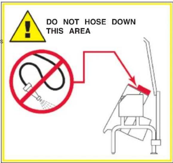
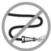
Unit should never be cleaned with a high pressure spray hose.

Stagnant Water
Do not leave water sitting in unit when not in use.
CLEANING INSTRUCTIONS
- Turn unit off.
- Remove drain screen (if applicable). Thoroughly wash and rinse the screen either in a sink or a dishwasher.
- Prepare a warm water and mild detergent solution in the unit.
- Remove food soil using a nylon brush.
- Loosen food which is stuck by allowing it to soak at a low temperature setting.
- Drain unit.
- Rinse interior thoroughly.
- If the unit is equipped with a Tangent Draw-Off Valve, clean as follows:
a) Disassemble the draw-off valve first by turning the valve knob counterclockwise, then turning the large hex nut counter-clockwise until the valve stem is free of the valve body.
b) In a sink, wash and rinse the inside of the valve body using a nylon brush.
c) Use a nylon brush to clean tangent draw-off tube.
d) Rinse with fresh water.
e) Reassemble the draw-off valve by reversing the procedure for disassembly. The valve's hex nut should be hand tight only.
- Using mild soapy water and a damp sponge, wash the exterior, rinse, and dry.
NOTES
→For more difficult cleaning applications one of the following can be used: alcohol, baking soda, vinegar, or a solution of ammonia in water.
→Leave the cover off when the kettle is not in use.
For more detailed instructions refer to Stainless Steel Equipment Care and Cleaning (www.nafem.org/resources/stainlesssteelfinal.doc) on Nafem's website (www.nafem.org).
MAINTENANCE

WARNING:
Any maintenance or service involving disassembly of components should be made by a qualified service technician. Ensure gas, electrical and water supply (if applicable) to the unit are shut off.
HINGE ADJUSTMENT INSTRUCTIONS

-
Fully lift cover to release spring tension.
-
Using a 7/16" deep socket adjust left and right bolts evenly.
-
When properly adjusted, cover should rest at 70^ .
LUBRICATION PROCEDURE
Lubricate the following parts every three months to insure smooth operation and reduce wear.
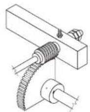
TRUNNION HOUSING, WORM SCREW AND TILT GEAR (prior to May 2006)
These parts are accessed through the top cover of the console.
Apply grease to gear teeth. Check for excessive play and adjust with adjusting screw located on top of cross bar.
TRUNNIONS (prior to May 2006)
These parts are accessed through the top cover of the console.
Apply grease to gear teeth. Check for excessive play and adjust with adjusting screw located on top of cross bar.
TRUNNION2 (after May 2006)
On the left hand side of the skillet there are two grease nipples on the top back portion of the trunnion housing.
natural_image
Technical line drawing of a mechanical assembly with gears and shafts (no text or symbols)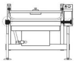
natural_image
Technical line drawing of a mechanical device with no visible text or symbols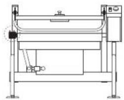
natural_image
Technical line drawing of a mechanical device with no visible text or symbolsBURNER ASSEMBLY GASKET EXAMINATION PROCEDURE
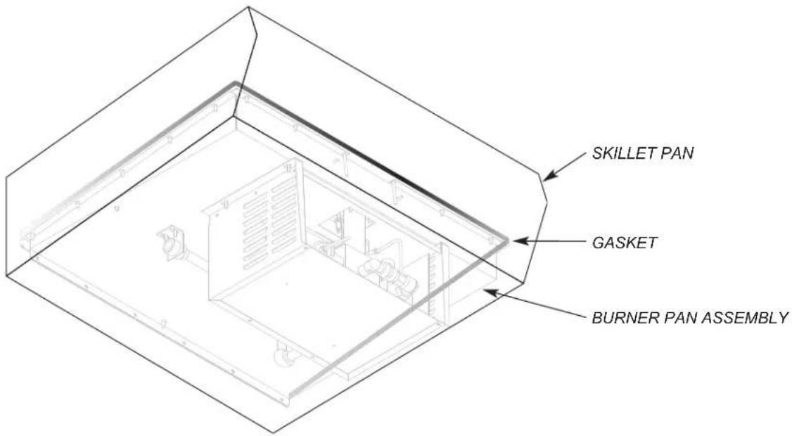
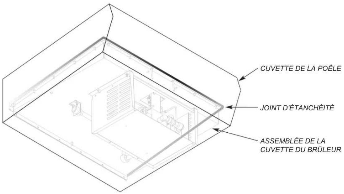
NOTE: It is imperative that this procedure be completed at least twice yearly.
- Turn unit to ON. The burner must be firing during this procedure.
- Using a stainless steel extension mirror, inspect gasket between burner pan assembly and skillet pan (sides and front only).
-
Replace gasket if:
-
gasket shows signs of deterioration
- a flame can be seen coming through the gasket
- condensation forms on the extension mirror (indicating escaping heat)
GASKET PART #s
30 GALLON 40 GALLON
SIDES SK2472402 SK2472402
FRONT SK2472400 SK2472401
When using these instructions refer to the SGL-TI wiring schematic.
- 115 VAC is sent through the 3 amp fuse to
■ The primary of the 24 VAC transformer
24 VAC is sent from the secondary of the
24VAC transformer to the Hi/Off/Low Switch.
■ Contacts of the RI Blower Relay
■ The optional Power Tilt Circuit
- With the Hi/Off/Low switch in the Low position.
■ 24 VAC is sent through the normally closed high limit switch to the mercury switch.
■ If the unit is in the down position then 24 VAC is sent through mercury switch to pin 9 on the thermostat.
- With the Hi/Off/Low Switch in the Hi position 24 VAC is also sent to the Hi terminal on the gas valve.
■ Gas will not leave the valve until the main gas valve opens (see step 7).
- If the steamer is calling for heat the 24 VAC is sent from pin number 10 to R1 Blower Relay.
■ The normally open contacts of the blower relay close sending 115 VAC to the blower.
■ The blower turns closing the air switch.
■ 24 VAC is sent through the now closed air switch to the ignition module.
-
Ignition module sends spark from terminal SP to the igniter.
-
Ignition module also sends 24 VAC from pins PV and MV/PV to the pilot coil of the gas valve pins P and C.
-
Pilot valve opens sending gas to the Pilot assembly.
■ Spark and gas meet and pilot is ignited.
■ AC current is passed through the flame and rectified then sent back to the ignition module. -
If the ignition module reads a minimum of 1.0 micro-amps through the burner ground then 24 VAC is sent from pins MV and MV/PV of the ignition module to pins M and C on the Gas valve.
■ The main (low) gas valve opens and gas (3.0" W.C. natural gas or 8.0" W.C. LP) is sent to the burner.
■ If the unit is in the Hi position (see step 3) 24VAC will be at the HI terminal and the gas pressure will be 3.5" W.C. natural or 10.0" W.C. LP.
■ Burner ignites until thermostat is satisfied.
- When thermostat is satisfied, 24 VAC is removed from pin 10 on the thermostat and the heat circuit is de-energized
- If the unit has the optional Power Tilt option and is in the down position, 115 VAC is sent from the customer connect through the circuit breaker and the up limit switch to the tilt switch.
- With the tilt switch in switch in the Up position
■ 115 VAC is sent to the Bridge Rectifier
115 VDC is sent from the rectifier through the 30-ohm resistor to the normally open RY10 and RY11 relay contacts.
■ 115 VAC is sent to the RY 10 relay coil.
■ The normally open RY10 contact close and 90 VDC is sent to the DC motor
■ The DC motor is energized and the unit tilts until the switch is released or the up limit switch opens.
- With the Tilt switch in the Down position
■ 115 VAC is sent to the Bridge Rectifier
115 DC is sent from the rectifier through the 30-ohm resistor to the normally open RY10 and RY11 relay contacts.
■ 115 VAC is sent to the RY 11 relay coil.
■ The normally open RY 11 contact close and the polarity of the 90 VDC is reversed.
■ The DC motor is energized and the unit lowers until the switch is released or the Down limit switch opens.
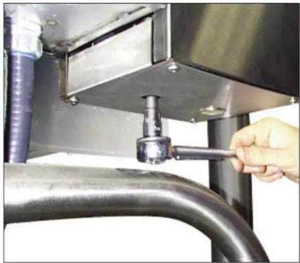
POWER TILT MANUAL OVERRIDE
In case of power failure or malfunction the skillet pan can be tilted manually following these instructions.
-
(prior to May 2006) - Fit a 10mm SIX point socket over the Manual Tilt Shaft as shown above. (after May 2006) - Fit a 1/2" SIX point socket over the Manual Tilt Shaft as shown above.
-
Turn socket wrench clockwise to empty contents.
natural_image
Close-up of a hand adjusting a pipe fitting into a stainless steel industrial piping system (no text or symbols visible)INSTALLATION
INSPECTION
If shipping damage to the unit is discovered or suspected, observe the following guidelines in preparing a shipping damage claim.
# D'ARTICLE DESCRIPTION
Lubricate the following parts every three months to insure smooth operation and reduce wear.
COMPARTIMENT DU TOURILLON, VIS TANGENTE ET EMBRAYAGE DE BASCULEMENT (avant mai 2006)
natural_image
Technical line drawing of a mechanical assembly with gears and shaft (no text or symbols)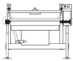
natural_image
Technical line drawing of a mechanical device with no visible text or symbols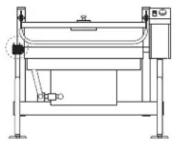
natural_image
Technical line drawing of a mechanical device with no visible text or symbolsBURNER ASSEMBLY GASKET EXAMINATION PROCEDURE
natural_image
Close-up of a hand adjusting a pipe fitting into a metal enclosure with a curved pipe (no text or symbols visible)Our Company supports a worldwide network of Maintenance and Repair Centers. Contact your nearest Maintenance and Repair Centre for replacement parts, service, or information regarding the proper maintenance and repair of your cooking equipment.
In order to preserve the various agency safety certification (UL, NSF, ASME/Ntl. Bd., etc.), only factory-supplied replacement parts should be used. The use of other than factory supplied replacement parts will void warranty.
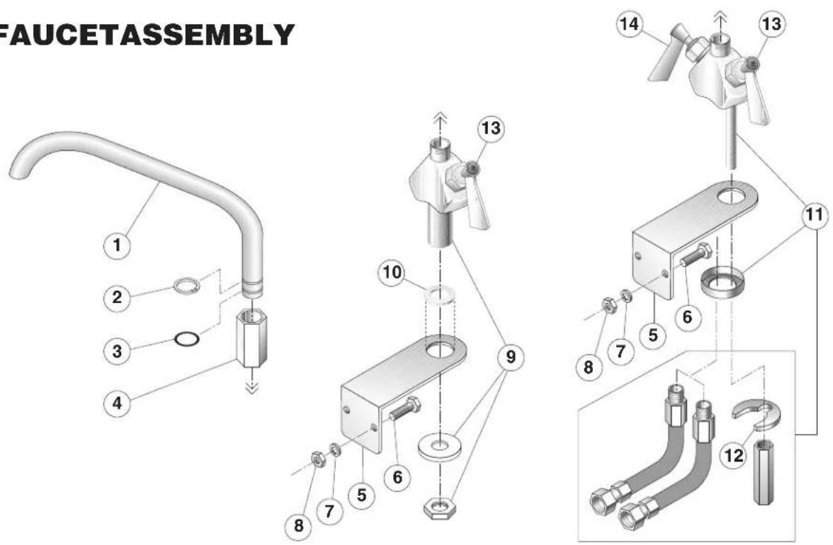
ITEM#PART#DESCRIPTIONQTY.
SPK13 SINGLE PANTRY FAUCET (includes items 1-10)
DPK13 DOUBLE PANTRY FAUCET (includes items 1-8 & 11)
| 1. | KE50825-7 | 3/4" SPOUT | 1 |
| 2. | FA95007-10 | RETAINING RING | 1 |
| 3. | FA05002-19 | "O" RING | 1 |
| 4. | KE51736 | LONG FAUCET NUT | 1 |
| 5. | SK00395-1 | FAUCET MOUNTING BRACKET | 1 |
| 6. | FA11258 | HEX CAP SCREW | 2 |
| 7. | FA31029 | LOCK WASHER | 2 |
| 8. | FA210028 | HEX NUT | 2 |
| 9. | KE51401 | SINGLE PANTRY BODY (c/w item 13) | 1 |
| 10. | KE50335 | ADAPTER WASHER | 1 |
| 11. | KE51403 | DOUBLE PANTRY BODY (c/w item 13 & 14) | 1 |
| 12. | SE50447 | REPLACEMENT HORSESHOE WASHER | 1 |
| 13. | SE50021 | REPLACEMENT STEM ASSEMBLY, COLD WATER | 1 |
| 14. | SE50020 | REPLACEMENT STEM ASSEMBLY, HOT WATER | 1 |
FRAME / LID ASSEMBLY

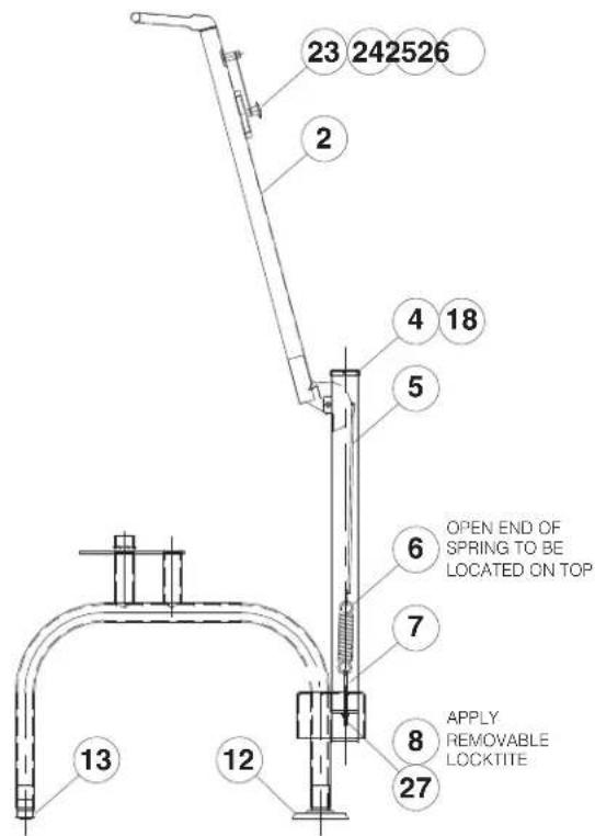
ITEM NO. PART NO. DESCRIPTION QTY.
- SK00392-1 FRAME WELDMENT (30 GALLON) 1
SK00392-2 FRAME WELDMENT (40 GALLON) 1 -
SK2457192 LID ASSEMBLY (30 GALLON) 1
SK2457193 LID ASSEMBLY (40 GALLON) 1 -
KE50187-1 CAP 2
-
SK00394-1 HOOK WELDMENT 2
-
SK2452300 SPRING 2
-
FA95087-1 EYE BOLT 2
-
FA20008 HEX NUT 2
-
KE53573-1 BEARING 2
-
FA15019-4 SHOULDER BOLT 2
-
FA21501-2 ACORN NUT 2
-
KE00099 ADJUSTABLE FOOT (FLANGED) 2
-
KE50249-1 FOOT ADJUSTOR (W/O FLANGE) 2
-
FA31029 LOCKWASHER 2
-
FA11054 SCREW 4
-
SK2459299 COUPLING ASSEMBLY 1
-
FA21024 HEX NUT (5/16-18) 2
-
FA31030 LOCKWASHER 2
-
FA30055 FLAT WASHER 2
-
SK00054 VENT COVER ASSEMBLY 1
-
SK2211200 SPACER 1
-
FA95081-1 BOLT, MODIFIED 1
-
SK50179 WASHER 1
-
FA30504 WASHER 2
2" TANGENT DRAW-OFF VALVE
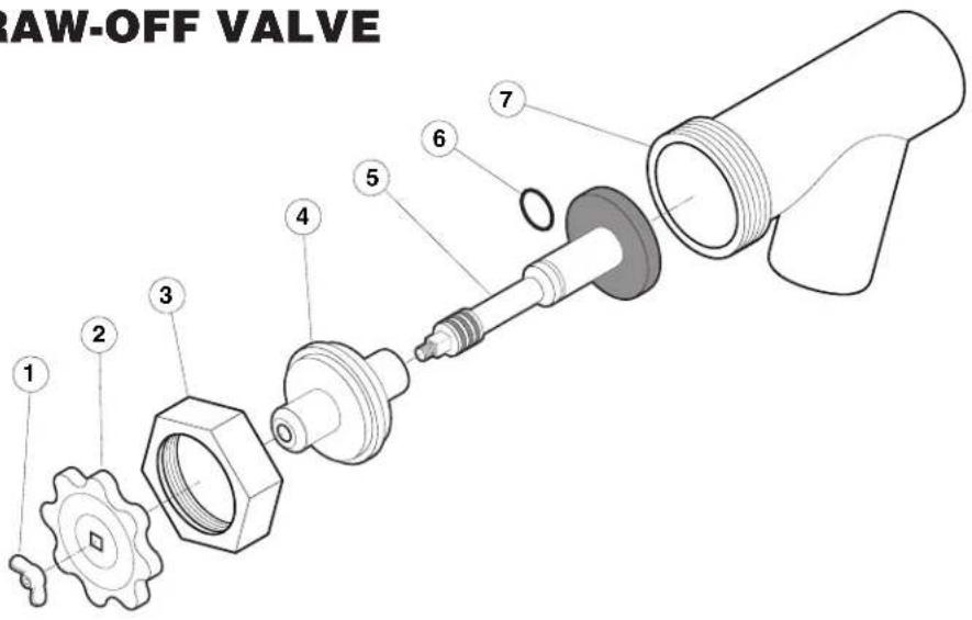
ITEM NO. PART NO. DESCRIPTION QTY.
-
-
- KE50972-B DRAW-OFF ASSEMBLY 1
-
- FA95049 WING NUT 1
- KE527551 KNOB 1
- KE52754 HEX NUT 1
- KE52753 RETAINER 1
- KE52752 PISTON 1
- FA00111 "O" RING 1
- KE52751 VALVE BODY 2
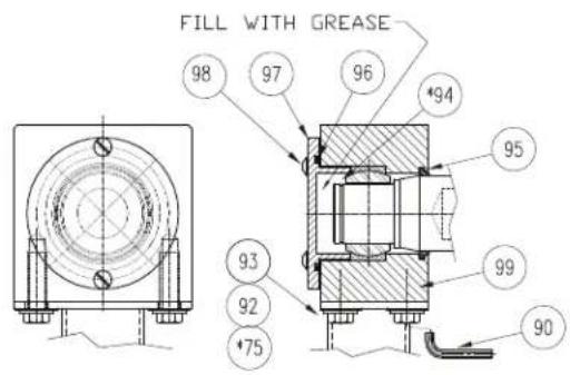
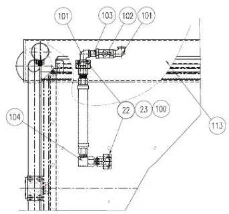
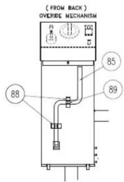
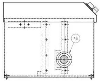
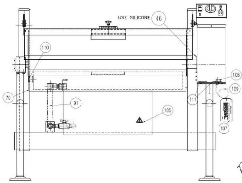
GENERAL ASSEMBLY COMPONENTS
VIEW X
(FULL VIEW, UNSECTIONED)
NOTE: ITEMS MARKED WITH * ARE NOT SHOWN.
CASTER OPTION
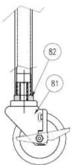
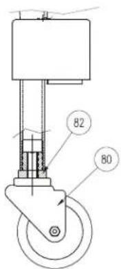
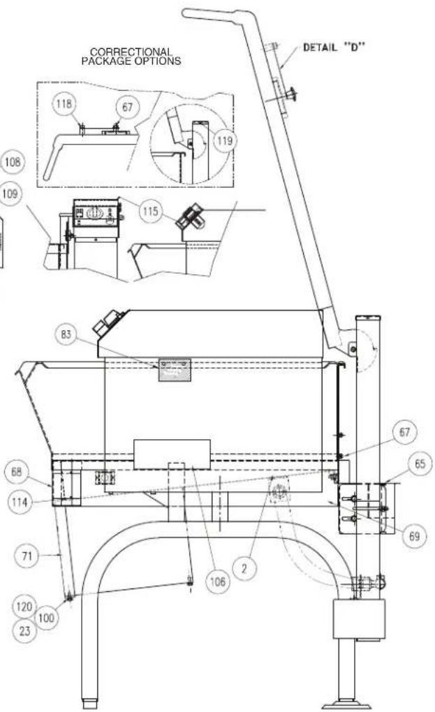
GENERAL ASSEMBLY COMPONENTS
ITEM NO. PART NO. DESCRIPTION QTY.
| 30 Gal. | 40 Gal. | ||||
| 22 | FA21008 HEX. NUT 1/4-20 4 4 | ||||
| 23 | FA31029 SPLIT LOCKWASHER 1/4 44 | ||||
| 46 | KE51084-2 WASHER | 11 | |||
| 65 | KE002486-1 | FLUE DEFLECTOR ASSEMBLY | 1 | - | |
| KE002486-2 | FLUE DEFLECTOR ASSEMBLY | - | 1 | ||
| 67 | FA21501-2 | ACORN NUT 1/4-20, S.S. | 5 5 | ||
| 68 | SK50942-1 FRONT COVER | 1 - | |||
| SK50942-2 FRONT COVER | - | 1 | |||
| 69 | SK50943-1 SIDE COVER, R.H. | 11 | |||
| 70 | SK50943-2 SIDE COVER, L. H. | 11 | |||
| 71 | SK50946-1 FRONT BOX COVER ASSEMBLY | 1 1 | |||
| 75 | FA11511-20 | SECURITY HEX SOCKET SCREW 3/8-16 X1 (CP OPTION) | 4 | 4 | |
| KE55443 CAP SCREW, 3/8-16 X1 HIGH STRENGTH (NO CP OPTION) | 4 4 | ||||
| 80 | KE53068-3 | SWIVEL CASTER W/O BRAKE | 2 2 | ||
| 81 | KE53068-4 | SWIVEL CASTER WITH BRAKE | 2 2 | ||
| 82 | KE53046-1 | CASTER SLEEVE | 4 4 | ||
| 83 | KE95447 LABEL TO COVER FAUCET MTG. HOLES | 1 1 | |||
| 85 | KE003160 | HANDLE WELDMENT | 11 | ||
| 88 | SK2473800 | SPRING CUP | 22 | ||
| 89 | F10 | SCREW: PAN QUAD 8-32 X 3/8 | 22 | ||
| 90 | FA11511-101 | SHORT ARM SECURITY HEX KEY | 1 1 | ||
| 91 | SK2495600 | STRIP FILL | 1 | - | |
| SK2474400 | STRIP FILL | - | 1 | ||
| 92 | KE55445 | WASHER, HIGH STRENGTH ULTRA-COATED | 4 | 4 | |
| 93 | FA31031 SPLIT LOCK WASHER, S.S., 3/8 DIA. | 4 4 | |||
| 94 | FA95007-12 | RETAINING RING, 1 DIA. 3/16 | 1 1 | ||
| 95 | KE55440 | WIPER SEAL | 1 1 | ||
| 96 | FA05002-47 | 0-RING, 2 DIA. X 2 DIA. 3/16 | 1 1 | ||
| 97 | KE55446 | PLATE, BEARING RETAINING | 1 1 | ||
| 98 | FA11511-2 | 10-32 X 3/8 PAN HEAD TORX SCREW (CP OPTION) | 4 | 4 | |
| F182 | 10-32 X 1/2 SLOTTED HEAD S.S. SCREW (NO CP OPTION) | 4 4 | |||
| 99 | KE02383 HOUSING ASSEMBLY, TRUNNION | 1 1 | |||
| 100 | FA30505-1 | FLAT WASHER 1/4 | 4 | 4 | |
| 101 | FA11258 | 1/4-20 X 3/4 BOLT, 18-8 S.S. | 4 | 4 | |
| 102 | F01518-1 | SHUT SET VALVE | 1 1 | ||
| 103 | N0640C1.5 | NIPPLE | 1 1 | ||
| 104 | SK2472702 | SWIVEL CONNECTOR | 1 1 | ||
| 105 | KE95497 | RISK OF ELECTRIC SYMBOL | 1 | 1 | |
| 106 | KE95552-2 LABEL, GAS RATING | 1 1 | |||
| 107 | KE95533-9 TAG | 1 1 | |||
| 108 | KE51258-1 CONDUIT CONNECTOR | 1 1 | |||
| 110 | KE54907-16 | PLUG BUTTON | 1 1 | ||
| 111 | KE55356 | EXTRUDEC WASHER | 4 | 4 | |
| 113 | KE55407 | EQUIPMENT INSTALLATION LABEL | 1 | 1 | |
| 114 | FAL1511-2 | 10-32 X 3/8 PAN HEAD TORX SCREW (CP OPTION) | 8 | 8 | |
| 114 | FL 82 | 10-32 X 1/2 S.S. SLOTTED HEAD SCREW (NO CP OPTION) | 8 | 8 | |
| 120 | FAL1511-11 | 1/4-20 X 3/4 PAN HEAD TORX SCREW (CP OPTION) | 2 | 2 | |
| FA11258 | 1/4-20 X 3/4 PAN HEAD CAP SCREW (NO CP OPTION) | 2 2 | |||
TILT ASSEMBLY COMPONENTS
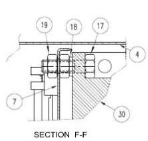
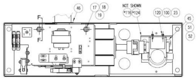
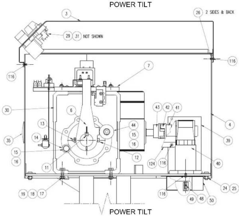
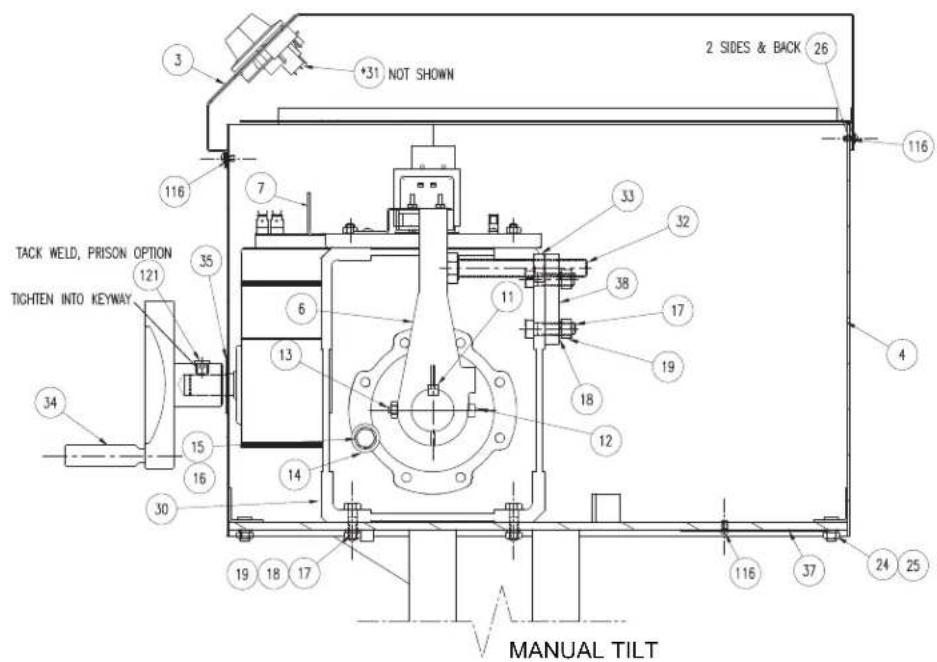
TILT ASSEMBLY COMPONENTS
Common Parts
| ITEM | PART# | DESCRIPTION | QTY |
| 4 | KE002590-2 | GB. WRAP WELDMENT | 1 |
| 6 | KE602239-1 | STOP ARM | 1 |
| 11 | FA95055-13 | KEY 3/8 X 3/8 X 5 | 1 |
| 12 | FA15019-6 | SHOULDER BOLT | 1 |
| 13 | FA21008 | 1/4-20 HEX NUT, 18-8 S.S. | 1 |
| 14 | KE601886-2 | STOP ASSEMBLY | 1 |
| 15 | FA15021 | BOLT, HEX CAP M10 X 30 | 2 |
| 16 | FA31500 | LOCKWASHER M10 | 2 |
| 17 | FA11526 | HEX. CAP SCREW 7/16-14 X 1-1/2" S.S. 18-8 | 6 |
| 18 | FA31011 | 7/16 SPLIT LOCKWASHER, PLATED | 6 |
| 19 | FA21506 | NUT, 7/16-14 S.S. 18-8 | 8 |
| 23 | FA31029 | SPLIT LOCKWASHER 1/4 | 9 |
| 24 | FA21024 | 5/16 - 18, HEX NUT, 18-8 S.S. | 4 |
| 25 | FA31030 | SPLIT LOCKWASHER 5/16 | 4 |
| 26 | KE600264-4 | GASKET, SILICONE GRAY | 1 |
| 30 | KE55513-1 | GEAR UNIT | 1 |
| 31 | WHSGLT1 | HARNESS FOR SGL T1 | 1 |
| 46 | KE51084-2 | WASHER | 1 |
| 100 | FA30505-1 | FLAT WASHER 1/4 | 9 |
Gearbox cover Assembly Option
| ITEM | PART# | DESCRIPTION | QTY |
| 3 | SK00387-15 | MANUAL TILT °F OPTION; 110-120 VOLT | 1 |
| SK00387-16 | MANUAL TILT °C OPTION; 110-120 VOLT | 1 | |
| SK00387-17 | POWER TILT °F OPTION; 110-120 VOLT | 1 | |
| SK00387-18 | POWER TILT °C OPTION; 110-120 VOLT | 1 | |
| SK00387-27 | MANUAL TILT °F OPTION; 220-240 VOLT | 1 | |
| SK00387-28 | MANUAL TILT °C OPTION; 220-240 VOLT | 1 | |
| SK00387-29 | POWER TILT °F OPTION; 220-240 VOLT | 1 | |
| SK00387-30 | POWER TILT °C OPTION; 220-240 VOLT | 1 |
Manual Tilt Option
| ITEM | PART# | DESCRIPTION | QTY |
| 17 | FA11526 | HEX CAP SCREW 7/16-14 X 1-1/2 S.S. 18-8 | 3 |
| 18 | FA31011 | 7/16 SPLIT LOCKWASHER, PLATED | 3 |
| 19 | FA21506 | NUT, 7/16-14 S.S. 18-8 | 3 |
| 32 | FA602714 | BOLT, HI-STRENGTH PLATED, 5/8-11 X 4-1/2 | 1 |
| 33 | FA15012 | HEX NUT, PLATED, 5/8-11 | 1 |
| 34 | KE00508-2 | HANDWHEEL ASSEMBLY | 1 |
| 35 | KE54738-5 | WASHER, FLAT | 1 |
| 37 | KE602511 | BOTTOM COVER | 1 |
| 38 | KE602710 | STOP PLATE | 1 |
| 110-120 V OPTION | |||
| 3 | SK00387-15 | MANUAL TILT °F OPTION; 110-120 VOLT | 1 |
| SK00387-16 | MANUAL TILT °C OPTION; 110-120 VOLT | 1 | |
| 7 | KE003653-1 | COMPONENT PLATE ASSEMBLY | 1 |
| 220-240 V OPTION | |||
| 3 | SK00387-27 | MANUAL TILT °F OPTION; 220-240 VOLT | 1 |
| SK00387-28 | MANUAL TILT °C OPTION; 220-240 VOLT | 1 | |
| 7 | KE003653-3 | COMPONENT PLATE ASSEMBLY | 1 |
Power Tilt Option
| ITEM | PART# | DESCRIPTION | QTY |
| 15 | FA15021 | BOLT, HEX CAP M10 X 30 | 1 |
| 16 | FA31500 | LOCKWASHER M10 | 1 |
| 23 | FA31029 | SPLIT LOCKWASHER 1/4 | 8 |
| 29 | WHST1-PTA | POWER TILT HARNESS FOR T1 | 1 |
| 35 | KE54907-16 | PLUG BUTTON | 1 |
| 39 | KE601725 | SUPPORT | 1 |
| 40 | KE52832-5 | MOTOR, POWER TILT | 1 |
| 41 | KE50582-5 | COUPLING HUB, 1/2 BORE | 1 |
| 42 | KE50583-1 | COUPLING SPIDER | 1 |
| 43 | KE50582-4 | COUPLING HUB, 3/4 BORE | 1 |
| 44 | KE601886-1 | STOP | 1 |
| 45 | FA11384 | HEX. CAP SCREW 3/8-16 X 1" | 2 |
| 48 | KE602542 | EXTENSION FOR SHAFT | 1 |
| 49 | KE602543 | SOCKET SET SCREW, CONE POINT | 1 |
| 50 | KE602507 | BOTTOM COVER | 1 |
| 51 | FA21026 | 3/8 HEXAGON NUT | 2 |
| 52 | FA31031 | 3/8 SPLIT LOCK WASHER S.S. | 2 |
| 100 | FA30505-1 | FLAT WASHER 1/4 | 2 |
| 116 | FA11145 | 10-32 X 3/8 PAN HEAD MACHINE SCREW | 2 |
| 120 | FA11258 | 1/4-20 X 3/4 HEX HEAD CAP SCREW | 2 |
| 124 | KE603730 | MOTOR GUARD | 1 |
| 110-120 V OPTION | |||
| 3 | SK00387-17 | POWER TILT °F OPTION; 110-120 VOLT | 1 |
| SK00387-18 | POWER TILT °C OPTION; 110-120 VOLT | 1 | |
| 7 | KE003653-2 | COMPONENT PLATE ASSEMBLY | 1 |
| 220-240 V OPTION | |||
| 3 | SK00387-29 | POWER TILT °F OPTION; 220-240 VOLT | 1 |
| SK00387-30 | POWER TILT °C OPTION; 220-240 VOLT | 1 | |
| 7 | KE003653-4 | COMPONENT PLATE ASSEMBLY | 1 |
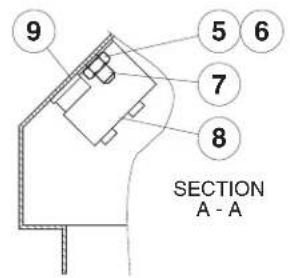
CONTROL BOX ASSEMBLY
(for units built prior to December 2008)
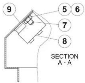
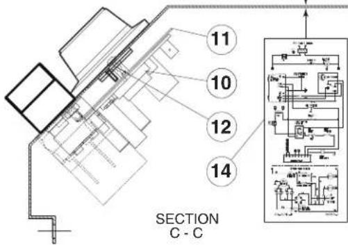
SECTION B-B
13
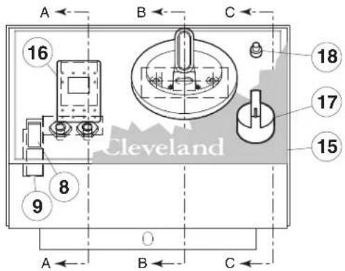
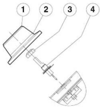
ITEM NO. PART NO. DESCRIPTION QTY.
| 1. | SK2138700 | KNOB ASSEMBLY | 1 |
| 2. | SK2360700 | DIAL INSERT °F | 1 |
| SK2360701 | DIAL INSERT °C | 1 | |
| 3. | KE51005 | RUBBER BOOT. #N9030 X 1/4 | 1 |
| 4. | SK2498399 | POTENTIOMETER SHAFT ASSEMBLY | 1 |
| INCLUDES | SK2166800 | POTENTIOMETER SHAFT | 1 |
| SK2167000 | TENSION PIN | 1 | |
| SK2167100 | WASHER, BOWED/SPRING | 1 | |
| SK2167200 | RETAINING RING, SP-NR #R1000-25 | 1 | |
| SK2167300 | PANEL BEARING | 1 | |
| SK2382800 | RETAINING RING CLIP | 1 | |
| 5. | FA21006 | NUT, S.S. F#10-24 | 2 |
| 6. | FA32022 | TOOTH LOCK WASHER #10 S.S. | 2 |
| 7. | FA40000-6 | #10-24 X 3/8 S.S. WELD STUD | 2 |
| 8. | SK50903-1 | BRACKET, INDICATOR LIGHT | 1 |
| 9. | SK50905-1 | HEAT INDICATOR, 28V | 1 |
| 10. | SK2142002 | THERMOSTAT | 1 |
| 11. | SK2159300 | THERMOSTAT INSULATOR | 1 |
| 12. | SK2491500 | STOP PLATE ASSEMBLY | 1 |
| 13. | SK95063 | CAUTION LABEL | 1 |
| 14. | SK90125-3 | WIRING DIAGRAM | 1 |
| 15. | KE95604-5 | CONTROLS LABEL, MANUAL TILT | 1 |
| KE95604-6 | CONTROLS LABEL, POWER TILT | 1 | |
| 16. | SK2474102 | SWITCH, ON/OFF/ON, DUAL FIRING | 1 |
| 17. | KE53137-3 | TILT SWITCH, ON/OFF/ON | 1 |
| KE53184 | CONTACT SECTION HOLDER (LATCH) | 1 | |
| KE53138-1 | CONTACT BLOCK | 4 | |
| 18. | KE50579-2 | CIRCUIT BREAKER | 1 |
| FA05002-34 | "O" RING, CIRCUIT BREAKER | 1 | |
| KE50580 | WATER RESISTANT BOOT | 1 |
CONTROL BOX ASSEMBLY
(for units built after December 2008)
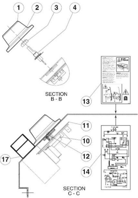
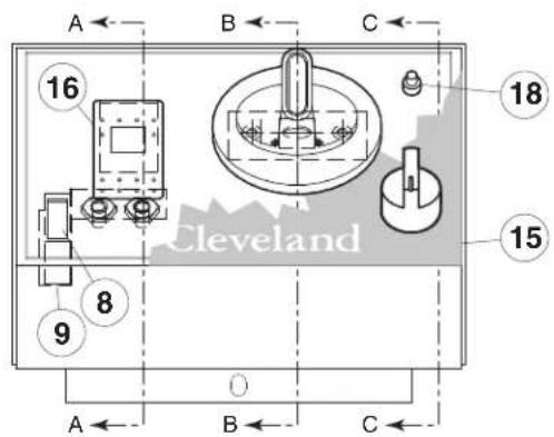
ITEM NO. PART NO. DESCRIPTION QTY.
| 1. | SK2138700 | KNOB ASSEMBLY | 1 |
| 2. | SK2360700 | DIAL INSERT °F | 1 |
| SK2360701 | DIAL INSERT °C | 1 | |
| 3. | KE51005 | RUBBER BOOT. #N9030 X 1/4 | 1 |
| 4. | SK2498399 | POTENTIOMETER SHAFT ASSEMBLY | 1 |
| INCLUDES | SK2166800 | POTENTIOMETER SHAFT | 1 |
| SK2167000 | TENSION PIN | 1 | |
| SK2167100 | WASHER, BOWED/SPRING | 1 | |
| SK2167200 | RETAINING RING, SP-NR #R1000-25 | 1 | |
| SK2167300 | PANEL BEARING | 1 | |
| SK2382800 | RETAINING RING CLIP | 1 | |
| 5. | FA21006 | NUT, S.S. F#10-24 | 2 |
| 6. | FA32022 | TOOTH LOCK WASHER #10 S.S. | 2 |
| 7. | FA40000-6 | #10-24 X 3/8 S.S. WELD STUD | 2 |
| 8. | SK50903-1 | BRACKET, INDICATOR LIGHT | 1 |
| 9. | SK50905-1 | HEAT INDICATOR, 28V | 1 |
| 10. | SK2142002 | THERMOSTAT | 1 |
| 11. | SK2159300 | THERMOSTAT INSULATOR | 1 |
| 12. | SK2491500 | STOP PLATE ASSEMBLY | 1 |
| 13. | SK95063 | CAUTION LABEL | 1 |
| 14. | SK90125-3 | WIRING DIAGRAM | 1 |
| 15. | KE95604-5 | CONTROLS LABEL, MANUAL TILT | 1 |
| KE95604-6 | CONTROLS LABEL, POWER TILT | 1 | |
| 16. | SK2474102 | SWITCH, ON/OFF/ON, DUAL FIRING | 1 |
| 17. | SE003687 | SWITCH ASSEMBLY REPLACEMENT KIT | 1 |
| INCLUDES | KE603208-4 | SWITCH | 1 |
| KE603208-7 | LATCH | 1 | |
| KE603208-9 | CONTACT | 4 | |
| KE603747 | LABEL | 2 | |
| 18. | KE50579-2 | CIRCUIT BREAKER | 1 |
| FA05002-34 | "O" RING, CIRCUIT BREAKER | 1 | |
| KE50580 | WATER RESISTANT BOOT | 1 |
SUPPORT PLATE ASSEMBLY
(for units built between August 2006 & June 2009)
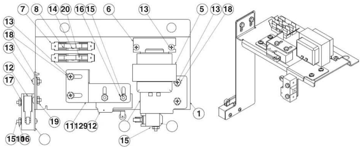
ITEM NO. PART NO.
SUB-ASSEMBLIES -
KE002907-5
KE002907-6
KE002907-7
KE002907-8
DESCRIPTION
QTY.
SUPPORT PLATE ASSEMBLY; MT, SGL-T1, 110-120V
SUPPORT PLATE ASSEMBLY; PT, SGL-T1, 110-120V
SUPPORT PLATE ASSEMBLY, MT, SGL-T1, 220-240V
SUPPORT PLATE ASSEMBLY, PT, SGL-T1, 220-240V
COMPONENT PARTS -
| 1 | KE602587 |
| 6 | KE53444 |
| 7 | KE51139 |
| 8 | KE52936-8 |
| 11 | KE602598 |
| 12 | SK2474500 |
| 13 | FA11091 |
| 14 | FA11054 |
| 15 | FA11060 |
| 16 | FA21002 |
| 17 | FA32004 |
| 18 | FA32005 |
110-120V, 1 PH, 60 HZ OPTION
| 5 | KE53838-25 |
| 20 | KE52936-6 |
220-240V, 1 PH, 50 HZ OPTION
| 5 | KE53838-18 |
| 20 | KE52936-10 |
POWER TILT OPTION -
| 9 | KE602573 |
| 10 | KE602571 |
| 12 | SK2474500 |
| 13 | FA11091 |
| 15 | FA11060 |
| 16 | FA21002 |
| 18 | FA32005 |
| 19 | FA21004 |
SUPPORT PLATE 1
BRACKET, TRANSFORMER MOUNTING 1
FUSE HOLDER 2
FUSE 1.25 AMP, 250V....1
BRACKET, SWITCH MOUNTING 1
SWITCH, TILT LIMIT 1
8-32 X 3/8 S.S. MACHINE SCREW....10
6-32 X 3/8 S.S. MACHINE SCREW....2
6-32 X 1 S.S. MACHINE SCREW 2
6-32 HEX MACHINE SCREW NUT S.S. 2
6 EXTERNAL TOOTH LOCK WASHER ZINC PLATED 6
8 EXTERNAL TOOTH LOCK WASHER ZINC PLATED 2
TRANSFORMER 1
FUSE 3.00 AMP, 250V....1
TRANSFORMER 1
FUSE 1.5 AMP, 250V....1
BRACKET, SWITCH MOUNTING 1
BRACKET, SWITCH MOUNTING 1
SWITCH, TILT LIMIT 2
8-32 X 3/8 S.S. MACHINE SCREW....4
6-32 X 1 S S MACHINE SCREW....4
6-32 HEX MACHINE SCREW NUT S S. 4
8 EXTERNAL TOOTH LOCK WASHER ZINC PLATED 4
8-32 HEX MACHINE SCREW NUT S S. 2
SUPPORT PLATE ASSEMBLY (for units built after June 2009)
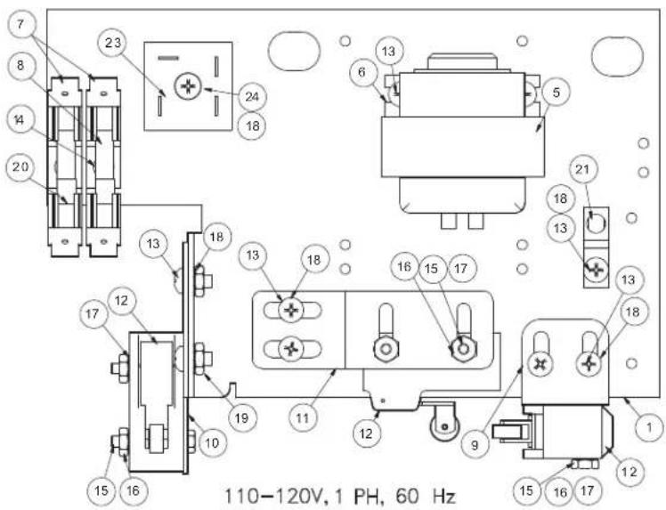
ITEM NO. PART NO. DESCRIPTION QTY.
COMMON PARTS:
| 1 | KE602587-1 | SUPPORT PLATE | 1 |
| 5 | KE53838-25 | TRANSFORMER | 1 |
| 6 | KE53444 | BRACKET, TRANSFORMER MOUNTING | 1 |
| 7 | KE51139 | FUSE HOLDER | 2 |
| 8 | KE52936-6 | FUSE 3.00 AMP, 250V | 1 |
| 11 | KE602598-1 | MOUNTING BRACKET; 5° TILT | 1 |
| 12 | SK2474500 | SWITCH, TILT LIMIT | 1/3 |
| 13 | FA11091 | #8-32 X 3/8 S.S. MACHINE SCREW | 5/7/9/11 |
| 14 | FA11054 | #6-32 X 3/8 S.S. MACHINE SCREW | 9 |
| 15 | FA11060 | #6-32 X 1 S.S. MACHINE SCREW | 2 |
| 16 | FA21002 | #6-32 HEX MACHINE SCREW NUT S.S. | 9 |
| 17 | FA32004 | #6 EXTERNAL TOOTH LOCK WASHER | 4 |
| 18 | FA32005 | #8 EXTERNAL TOOTH LOCK WASHER | 1 |
| 20 | KE52936-8 | FUSE 1.25 AMP, 250V | 2 |
| 21 | KE50473 | GROUND LUG | 1 |
110-120V, POWER TILT MODELS:
| 9 | KE602573-1 | BRACKET, LIMIT SWITCH MOUNTING | 1 |
| 10 | KE602571 | MOUNTING BRACKET: FULL TILT | 1 |
| 19 | FA21004 | #8-32 HEX MACHINE SCREW NUT S.S. | 2 |
| 23 | KE50581 | BRIDGE RECTIFIER | 1 |
| 24 | FA15018-8 | 8-32 X 1 SEMS SCREW | 1 |
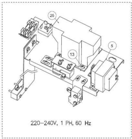
220-240V, MANUAL TILT MODELS:
25 KE53838-10 TRANSFORMER
1
20-240V, POWER TILT MODELS:
| 9 | KE602573-1 | BRACKET, LIMIT SWITCH MOUNTING | 1 |
| 10 | KE602571 | MOUNTING BRACKET: FULL TILT | 1 |
| 19 | FA21004 | #8-32 HEX MACHINE SCREW NUT S.S. | 2 |
| 23 | KE50581 | BRIDGE RECTIFIER | 1 |
| 24 | FA15018-8 | 8-32 X 1 SEMS SCREW | 1 |
| 25 | KE53838-10 | TRANSFORMER | 1 |
COMPONENT PLATE ASSEMBLY, POWER TILT
(for units built between August 2006 & June 2009)
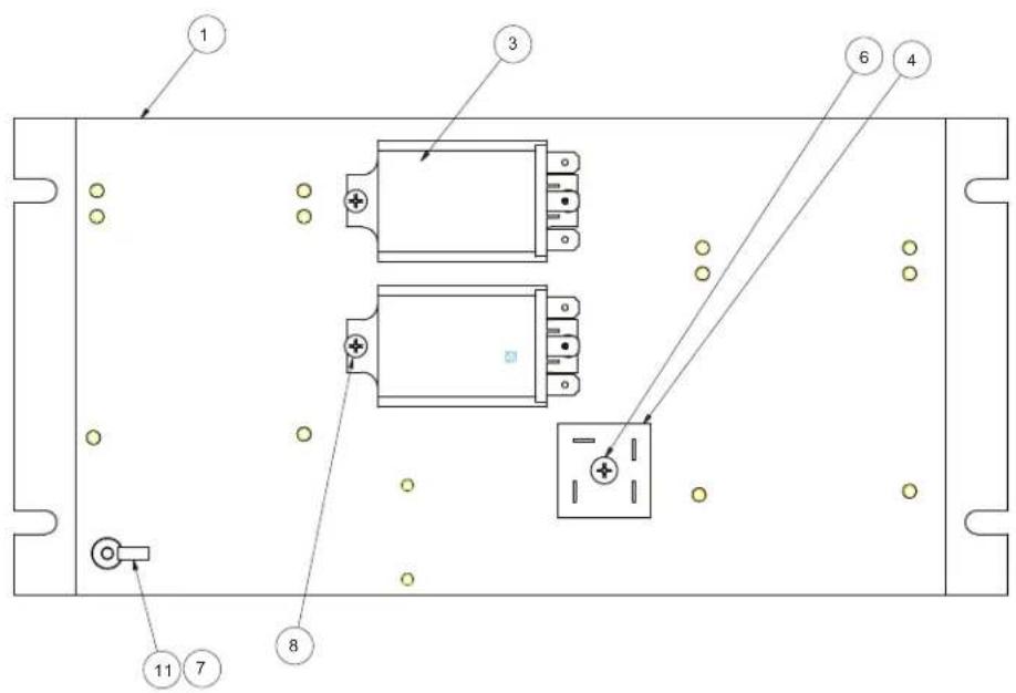
ITEM NO. PART NO. DESCRIPTION QTY.
| 1 | KE602908 | COMPONENT PLATE | 1 |
| 3 | KE50753-10 | RELAY; DPDT/10A/120VAC | 2 |
| 4 | KE50581 | BRIDGE RECTIFIER | 1 |
| 6 FA15018-8 #8-32 X 1 SEMS MACHINE SCREW, PLATED | 1 | ||
| 7 | FA11091 | #8-32 X 3/8 S.S. MACHINE SCREW | 9 |
| 8 | FA11056 | #6-32 X 1/2 S.S. MACHINE SCREW | 4 |
| 11 | KE50473 | GROUND LUG | 1 |
BURNER ASSEMBLY
(for units built prior to June 2007)
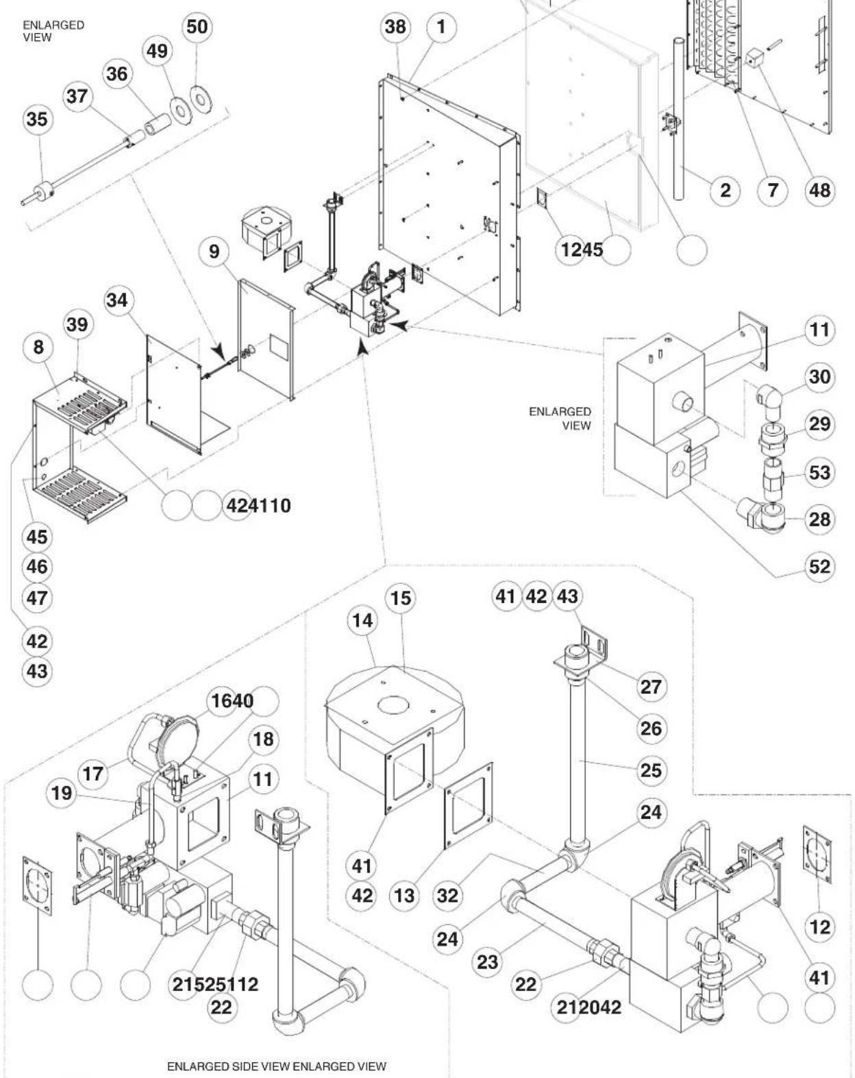
BURNER ASSEMBLY (for units built prior to June 2007)
ITEM NO. PART NO. DESCRIPTION QTY.
- SK00399-1 BURNER PAN ASSEMBLY (30 GALLON) 1
SK00389-1 BURNER PAN ASSEMBLY (40 GALLON) 1 - SK2495500 BURNER ASSEMBLY (30 GALLON) 1
SK2478800 BURNER ASSEMBLY (40 GALLON) 1 - SK2460300 INSULATION, SIDE 2
- SK2460700 INSULATION, BURNER/IGNITOR 1
- SK2460500 INSULATION FRONT (30 GALLON) 1
SK2460400 INSULATION FRONT (40 GALLON) 1 - SK50939-1 INSULATION BOTTOM (30 GALLON) 1
SK50919-1 INSULATION BOTTOM (40 GALLON) 1 - SK2494999 BAFFLE ASSEMBLY (30 GALLON) 1
SK2471099 BAFFLE ASSEMBLY (40 GALLON) 1 - SK00396-1 BOX ASSEMBLY 1
- SK2471200 HEAT SHIELD (30 GALLON) 1
SK50927-1 HEAT SHIELD (40 GALLON) 1
10.* SK00397-1 GAS IGNITION CONTROL ASSEMBLY. 1
* SEE "GAS IGNITION CONTROL SYSTEM" DRAWING FOR MORE DETAIL - SK2463299 AIR MIX CHAMBER ASSEMBLY 1
- SK2460000 GASKET, BURNER MOUNTING 2
- SK2460200 GASKET, FAN MOUNTING 1
- SK2476000 BLOWER FAN 1
- SK2480101 AIR ORIFICE: BLOWER (30 GALLON) 1
SK2480100 AIR ORIFICE: BLOWER (40 GALLON)....1 - SK2488100 AIR SWITCH 1
- SK2491100 1/4 TUBE AIR PROVE 1
- SK2473000 COMPRESSION TEE 1
- SK2491200 1/4 TUBE AIR MIX - IGNITOR 1
- SK2491300 1/4 TUBE GAS VALVE ELBOW COMPT. 1
- FI05226-1 NIPPLE 1
- FI00073-1 UNION 1
- FI05226-7 NIPPLE 1
- FI00040-1 ELBOW 2
- SK01477-11 NIPPLE (30 GALLON) 1
SK01477-12 NIPPLE (40 GALLON)....1 - FI05231 REDUCER 1
- SK2459299 COUPLING ASSEMBLY 1
- SK076015-2 ELBOW, 3/4 UNION 1
- SK076029-70 UNION 1
- SK2489700 STREET ELBOW 1
- FI05226-8 NIPPLE 1
- SK2462899 COVER ASSEMBLY, GAS COMPT. BOX 1
- SK50933-1 SENSOR 1
- SK2490600 FULL COUPLING, S.S. 1
- SK2487800 BAYONET, ADAPTER 1
- F95 PAL NUT 15-19
- F10 SCREW, PAN QUARD, 8-32X3/8 .6
- F900 K-LOCK NUT, 10-24 .3
- FA21008 HEX NUT, 1/4 -20 S.S. . . . . . . . . . . . . . . . . . . . . . . . . . . . . . . . . . . . . . . . . . . . . . . . . . . . . . . . . . . . . . . . . . . 23-25
- FA31029 SPLIT LOCKWASHER, 1/4-S.S. . . . . . . . . . . . . . . . . . . . . . . . . . . . . . . . . . . . . . . . . . . . . . . . . . . . . . . . . . . . . . . . . . 23-25
- FA11258 HEX SCREW, 1/4-20 X 3/4 . . . . . . . . . . . . . . . . . . . . . . . . . . . . . . . . . . . . . . . . . . . . . . . . . . . . . . . . . . . . . . . 8-10
- FA30505-1 WASHER, 1/4 13-15
- SK50399 CONNECTOR, 1/2 LIQUIDTIGHT 1
- KE54617-1 CONNECTOR, 45 DEG. 1/2 TIGHT ..... 1
- KE51916-2 1/2 LIQUIDTIGHT 1
- SK50941-1 PROBE INSULATION (30 GALLON) 1
SK50941-2 PROBE INSULATION (40 GALLON) 1 - FA30505-3 WASHER 1
- SK2460900 GASKET 1
51.* SK00398-1 PILOT ASSEMBLY, NATURAL GAS 1
SK00398-2 PILOT ASSEMBLY, LP 1
* SEE "PILOT ASSEMBLY" DRAWING FOR MORE DETAIL - KE003671-1 GAS VALVE KIT, NATURAL GAS 1
KE003671-2 GAS VALVE KIT, LP 1 - SK2499600 ORIFICE, NATURAL GAS (30 GALLON) 1
SK2473100 ORIFICE, NATURAL GAS (40 GALLON) 1
SK2499700 ORIFICE, LP. (30 GALLON) 1
SK2473200 ORIFICE, LP. (40 GALLON) 1
BURNER ASSEMBLY (for units built after after June 2007)
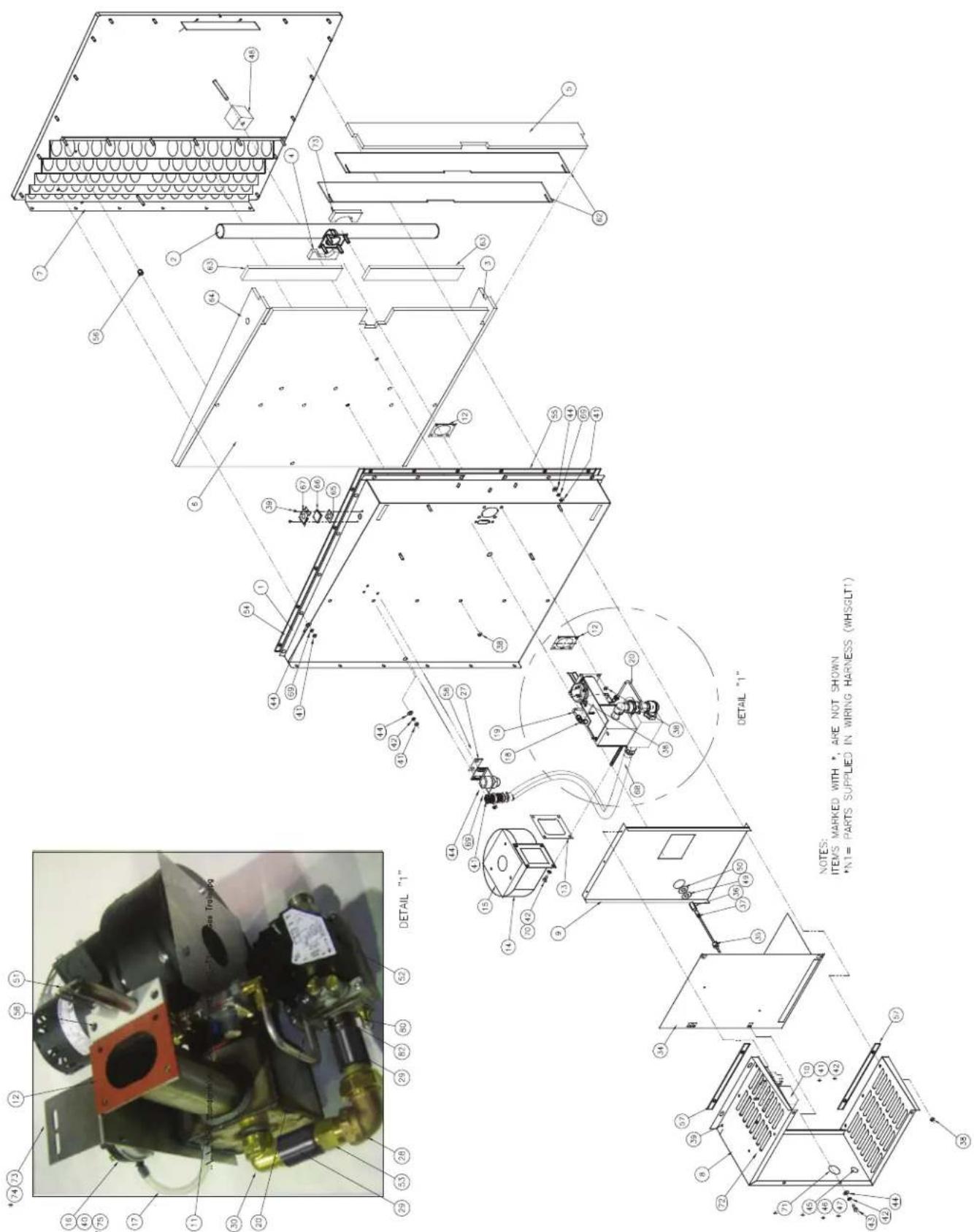
| - | SK00388-4 | BURNER UNIT ASSEMBLY, 40 GAL. LP. | ▼ | |||
| - | SK00388-3 | BURNER UNIT ASSEMBLY, 30 GAL. LP. | ▼ | |||
| - | SK00388-2 | BURNER UNIT ASSEMBLY, 40 GAL. NAT. GAS | ▼ | |||
| - | SK00388-1 | BURNER UNIT ASSEMBLY, 30 GAL. NAT GAS | ▼ | |||
| ITEM | PART# | DESCRIPTION | QTY | QTY | QTY | QTY |
| 43 | FA11258 | HEX. SCREW, 1/4-20 X 3/4 | 4 | 4 | 4 | 4 |
| 44 | FA30505-1 | WASHER, 1/4 | 21 | 23 | 21 | 23 |
| 45 | SK50399 | CONNECTOR 1/2 LIQUIDTIGHT | *N1 | *N1 | *N1 | *N1 |
| 46 | KE54617-1 | CONNECTOR, 45 DEC. 1/2 TIGHT | *N1 | *N1 | *N1 | *N1 |
| 47 | KE51916-2 | 1/2 LIQUIDTIGHT | *N1 | *N1 | *N1 | *N1 |
| 48 | SK50941-1 | PROBE INSULATION | 1 | - | 1 | - |
| SK50941-2 | PROBE INSULATION | - | 1 | - | 1 | |
| 49 | FA30505-3 | WASHER | 1 | 1 | 1 | 1 |
| 50 | SK2460900 | GASKET | 1 | 1 | 1 | 1 |
| 51 | SK00398-1 | PILOT ASSEMBLY, NATURAL GAS | 1 | 1 | - | - |
| SK00398-2 | PILOT ASSEMBLY, LP. | - | - | 1 | 1 | |
| 52 | SK24882-1 | STANDARD GAS VALVE FOR NATURAL GAS | 1 | 1 | - | - |
| SK24882-2 | STANDARD GAS VALVE FOR LP | - | - | 1 | 1 | |
| 53 | REF.KE55278 | GAS ORIFICE.REF. TO DWG. FOR SELECTION | 1 | 1 | 1 | 1 |
| 54 | SK2472402 | GASKET, PAN TO BURNER PAN ( SIDE) | 2 | 2 | 4 | 4 |
| 55 | SK2472400 | GASKET, PAN TO BURNER PAN ( FRONT) | 1 | - | 2 | - |
| SK2472401 | GASKET, PAN TO BURNER PAN ( FRONT) | - | 1 | - | 2 | |
| 56 | SK2463800 | SPACER | 4 | 6 | 4 | 6 |
| 57 | SK2461000 | GASKET, COMPONENT MOUNTING | 2 | 2 | 2 | 2 |
| 58 | SK2498500 | GASKET, GAS LINE MOUNT | 1 | 1 | 1 | 1 |
| 62 | SK600116-1 | INSULATION BURNER, FRONT THIN | 2 | - | 2 | - |
| SK600116-2 | INSULATION BURNER, FRONT THIN | - | 2 | - | 2 | |
| 63 | SK600117-1 | INSULATION UNDER BURNER | 2 | - | 2 | - |
| SK600117-2 | INSULATION UNDER BURNER | - | 2 | - | 2 | |
| 64 | KE600641-2 | INSULATION, SIDE | 1 | 1 | 1 | 1 |
| 65 | KE53618 | SIGTH CLASS GASKET | 1 | 1 | 1 | 1 |
| 66 | KE53617 | SIGTH CLASS | 1 | 1 | 1 | 1 |
| 67 | KE53619 | SIGTH CLASS RETAINER | 1 | 1 | 1 | 1 |
| 68 | KE603155 | FLEXIBLE S.S GAS HOSE | 1 | 1 | 1 | 1 |
| 69 | FA32008 | TOOTH LOCK WASHER | 14 | 16 | 14 | 16 |
| 70 | FA11256 | BOLT 1/4"-20, 1/2" | 4 | 4 | 4 | 4 |
| 71 | KE50555-7 | GROMMET RUBBER | 1 | 1 | 1 | 1 |
| 72 | FA20504-3 | 10-24 LOCK NUT, ZINK COATED | 1 | 1 | 1 | 1 |
| 73 | KE602274 | BRACKET, AIR SWITCH MOUNTING | 1 | 1 | 1 | 1 |
| 74 | SK2460701 | INSULATION, BURNER/IGNITOR | 1 | 1 | 1 | 1 |
| 75 | FA11092 | PAN HEAD PHILLIPS S.S. SCREW #8-32 X 1/2 | 2 | 2 | 2 | 2 |
| 80 | G02251-1 | GAS SPIGOT | 1 | 1 | 1 | 1 |
| 82 | N0640C1-5 | NIPPLE 3/4 X 1 1/2 LG, BLACK PIPE | 1 | 1 | 1 | 1 |
| - | SK00388-4 | BURNER UNIT ASSEMBLY, 40 GAL. LP. | ▼ | |||
| - | SK00388-3 | BURNER UNIT ASSEMBLY, 30 GAL. LP. | ▼ | |||
| - | SK00388-2 | BURNER UNIT ASSEMBLY, 40 GAL. NAT. GAS | ▼ | |||
| - | SK00388-1 | BURNER UNIT ASSEMBLY, 30 GAL NAT GAS | ▼ | |||
| ITEM | PART# | DESCRIPTION | QTY | QTY | QTY | QTY |
| 1 | SK00399-1 | BURNER PAN ASSEMBLY | 1 | - | 1 | - |
| SK00389-1 | BURNER PAN ASSEMBLY | - | 1 | - | 1 | |
| 2 | SK2478801 | BURNER ASSEMBLY | 1 | - | 1 | - |
| SK2478800 | BURNER ASSEMBLY | - | 1 | - | 1 | |
| 3 | KE600641-1 | INSULATION, SIDE | 1 | 1 | 1 | 1 |
| 4 | SK2460700 | INSULATION, BURNER/IGNITOR | 1 | 1 | 1 | 1 |
| 5 | SK2460500 | INSULATION FRONT | 1 | - | 1 | - |
| SK2460400 | INSULATION FRONT | - | 1 | - | 1 | |
| 6 | SK50939-1 | INSULATION BOTTOM | 1 | - | 1 | - |
| SK50919-1 | INSULATION BOTTOM | - | 1 | - | 1 | |
| 7 | SK2494999 | BAFFLE ASSEMBLY | 1 | - | 1 | - |
| SK2471099 | BAFFLE ASSEMBLY | - | 1 | - | 1 | |
| 8 | SK00396-1 | BOX ASSEMBLY | 1 | 1 | 1 | 1 |
| 9 | SK50927-1 | HEAT SHIELD | 1 | 1 | 1 | 1 |
| 10 | SK00397-1 | GAS IGNITION CONTROL ASSY (STANDARD SKILLETS). | 1 | 1 | 1 | 1 |
| 11 | KE02411 | AIR MIX CHAMBER ASSEMBLY | 1 | 1 | 1 | 1 |
| 12 | SK2460000 | GASKET: BURNER MOUNTING | 2 | 2 | 2 | 2 |
| 13 | SK2460200 | GASKET: FAN MOUNTING | 1 | 1 | 1 | 1 |
| 14 | SK2476000 | BLOWER FAN (STANDARD SKILLETS) | 1 | 1 | 1 | 1 |
| 15 | SK2480102 | AIR ORIFICE: BLOWER | 1 | - | 1 | - |
| SK2480100 | AIR ORIFICE: BLOWER | - | 1 | - | 1 | |
| 16 | KE55453-1 | AIR PRESSURE SWITCH | 1 | 1 | 1 | 1 |
| 17 | KE55501 | TUBE, AIR SWITCH FLEXIBLE | 1 | 1 | 1 | 1 |
| 18 | FI05198-1 | ELBOW; COMPRESSION 1/4 TUBEX1/8 MPT | 1 | 1 | 1 | 1 |
| 19 | SK2491200 | 1/4 TUBE AIR MIX - IGNITOR | 1 | 1 | 1 | 1 |
| 20 | SK24913-2 | 1/4 TUBING COMP; T1 GAS VALVE | 1 | 1 | 1 | 1 |
| 27 | SK2459299 | COUPLING ASSEMBLY | 1 | 1 | 1 | 1 |
| 28 | SK076015-2 | ELBOW: 3/4 UNION | 1 | 1 | 1 | 1 |
| 29 | SK076010-4 | PIPE COUPLING - WS TYPE; 3/4 | 2 | 2 | 2 | 2 |
| 30 | SK2489700 | STREET ELBOW | 1 | 1 | 1 | 1 |
| 34 | SK2462899 | COVER ASSEMBLY,GAS COMP.BOX | 1 | 1 | 1 | 1 |
| 35 | SK50933-1 | OPERATING THERMOSTAT | 1 | 1 | 1 | 1 |
| 36 | SK2490600 | COUPLING, 1/8 NPT SS. | 1 | 1 | 1 | 1 |
| 37 | SK2487800 | BAYONET, ADAPTOR | 1 | 1 | 1 | 1 |
| 38 | FA20502 | FLANCED NUT | 14 | 16 | 14 | 16 |
| 39 | F10 | THREAD-CUTTING SCREW, 8-32 X3/8" | 8 | 8 | 8 | 8 |
| 40 | F900 | K-LOCK NUT, 10-24 | 3 | 3 | 3 | 3 |
| 41 | FA21008 | HEX. NUT, 1/4 -20 S.S. | 23 | 25 | 23 | 25 |
| 42 | FA31029 | SPLIT LOCKWASHER, 1/4-S.S. | 11 | 11 | 11 | 11 |
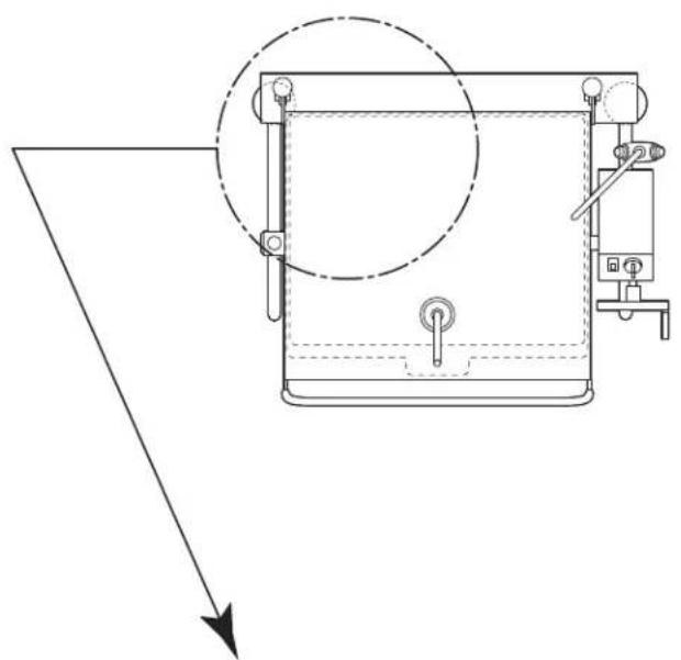
GAS TRAIN, TRUNNION ASSEMBLIES
ITEM PART DESCRIPTION QTY. NO. NO.
GAS TRAIN
- FI00134 ELBOW 2
- F01518-1 SHUT OFF VALVE ..... 1
- FI00607 NIPPLE 1
- SK2472702 SWIVEL CONNECTOR .....1
- SK2472701 GAS CONNECTOR HOSE .....1
- SK2459299 BRACKET ASSEMBLY, GAS LINE ...1
natural_image
Pure technical diagram of a mechanical device with no text, numbers, or symbols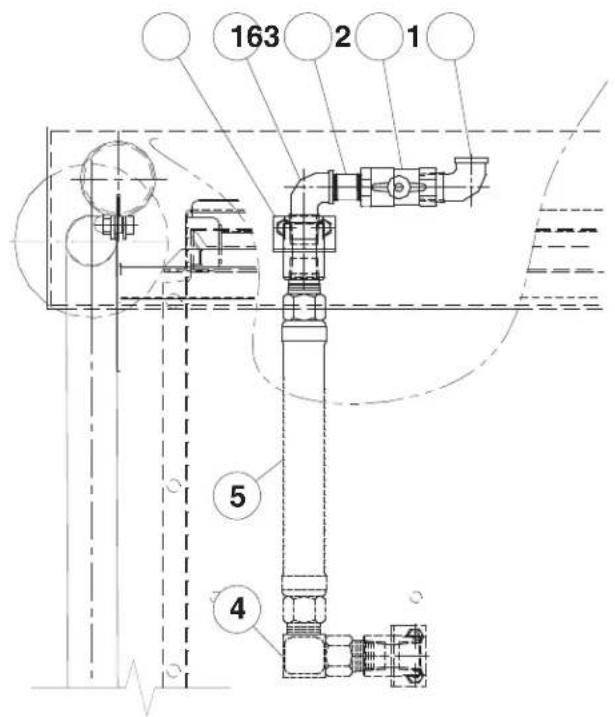
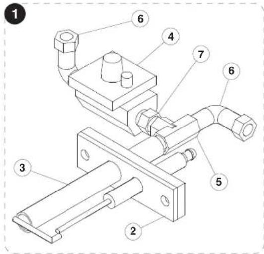
PILOT ASSEMBLY
ITEM PART DESCRIPTION QTY. NO. NO.
-
K00398-1 PILOT ASSEMBLY, NATURAL GAS ..... 1 SK00398-2 PILOT ASSEMBLY, LP ..... 1
-
SK2460100 GASKET 1
- SK2477000 IGNITOR/PILOT ASSEMBLY .....1
- SK2488300 GAS REGULATOR ....1
- SK2489800 TEE, 1/8 ..... 1
- FI05198-1 ELBOW, 1/8 2
- SK2488400 VARIABLE ORIFICE NATURAL GAS ....1 SK2488401 VARIABLE ORIFICE PROPANE ....1
GAS IGNITION CONTROL SYSTEM
ITEM PART DESCRIPTION QTY. NO. NO.
-
SK00397-1 GAS IGNITION CONTROL ASSEMBLY..1
-
SK50931-1 MOUNTING PLATE 1
- SK2475300 GAS CONTROL MODULE ..... 1
- KE55069-7 HIGH LIMIT (INCLUDES MOUNTING BRACKET SK50931) 1
- FA12 SCREW, 10-24 X 3/8 8
- SK2475600 HOLDER 1
- SK2475500 RELAY .... 1 SK2475700 SPRING .... 1

FLUE DIVERTER ASSEMBLY
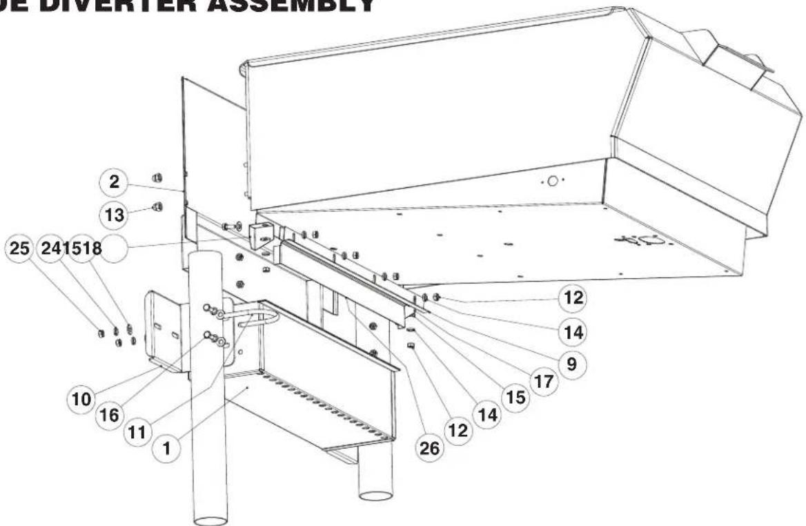
ITEM NO. PART NO. DESCRIPTION QTY
| 1. | KE002440-1 | CHANNEL WLD'T ASS'Y; 30 | 1 |
| KE002440-2 | CHANNEL WLD'T ASS'Y; 40 | 1 | |
| 2. | KE602434-1 | FLUE FRONT; 30 | 1 |
| KE602434-2 | FLUE FRONT; 40 | 1 | |
| 9. | KE602438-1 | ANGLE; 30 | 1 |
| KE602438-1 | ANGLE; 30 | 1 | |
| 10. | KE602444 | BRACKET; FRAME CLAMP | 2 |
| 11. | FA95092-3 | U; 3" FRAME CLAMP | 2 |
| 12. | FA21008 | HEX NUT; S.S.; 1/4-20 | 6/8 |
| 13. | FA21501-2 | HEX HEAD DOMED NUT; S.S.; 1/4-20 | 4 |
| 14. | FA31029 | SPRING LOCK WASHER; 1/4 I.D. | 10/12 |
| 15. | FA30505-1 | FLAT WASHER; S.S.; 1/4 I.D. | 14/16 |
| 16. | FA11258 | HEX HEAD SCREW; S.S.; 1/4-20 X3/4 | 8/10 |
| 17. | KE602373-1 | FILLER PIECE; R.H. | 1 |
| 18. | KE602373-2 | FILLER PIECE; L.H. | 1 |
| 19. | SK2330100 | SILICONE (NOT SHOWN) | 1 |
| 22. | SK2472405 | GASKET, PAN TO FLUE (NOT SHOWN); 30 | 1 |
| SK2472406 | GASKET, PAN TO FLUE (NOT SHOWN); 40 | 1 | |
| 23. | KE602382 | INSULATION (NOT SHOWN) | 1 |
| 24. | FA31030 | SPRING LOCK WASHER, 5/16"I.D. | 4 |
| 25. | FA21024 | HEX NUT, S.S. 5/16"-18 | 4 |
| 26. | KE602568-1 | FLUE BACK; 30 | 1 |
| KE602568-2 | FLUE BACK; 40 | 1 | |
| 27. | KE802607 | INSTALLATION INSTRUCTIONS FOR SERVICE (NOT SHOWN) | 1 |
SPARE PARTS LIST
PART NO. DESCRIPTION QTY.
SK2474500 SWTCH, TILT LIMIT 1
KE53838-25 TRANSFORMER 1
KE52936-8 FUSE, 1.25 AMP 1
KE52936-6 FUSE, 3 AMP 1
SK00397-1 GAS IGNITION CONTROL ASSEMBLY. 1
SK50933-1 TEMPERATURE SENSOR (RTD) 1
SK2488201 GAS VALVE, LP 1
FA15019-6 SHOULDER BOLT 1
FA21024 5-16 HEX NUT, 18-8 S.S. 1
SK2498399 POTENTIOMETER SHAFT ASSEMBLY 1
INCLUDES:
SK2166800 POTENTIOMETER SHAFT 1
SK2167000 TENSION PIN 1
SK2167100 WASHER, BOWED/SPRING 1
SK2167200 RETAINING RING, SP-NR #R1000-25 1
SK2167300 PANEL BEARING 1
SK2382800 RETAINING RING CLIP 1
SK50905-1 INDICATOR LIGHT CLEAR, 28V 1
SK2142002 THERMOSTAT 1
SK2477000 IGNITOR/PILOT ASSEMBLY 1
KE55069-7 SAFETY THERMOSTAT 1
SK2475500 RELAY 1
SK2474102 SWITCH, ON/OFF/ON, DUAL FIRING 1
POWER TILT ONLY
KE53137-3 TILT SWITCH, ON/OFF/ON 1
KE53184 CONTACT SECTION HOLDER (LATCH) 1
KE53138-1 CONTACT BLOCK 4
KE50579-2 CIRCUIT BREAKER 1
FA05002-34 "O" RING, CIRCUIT BREAKER 1
KE50580 WATER RESISTANT BOOT 1

- FOR THE USER
- FOR YOUR SAFETY
- RETAIN THIS MANUAL FOR YOUR REFERENCE
- POUR L'UTILISATEUR
- POUR VOTRE SÉCURITÉ
- Product Bulletin Cleveland Range Ltd
- WARNING
- Installation Instructions
- INSTALLATION
- INSPECTION
- CLEARANCE REQUIREMENTS
- SHIPPING DAMAGE INSTRUCTIONS
- GENERAL
- GAS
- ENSURE THE GAS SUPPLY MATCHES THE KETTLE'S REQUIREMENTS AS STATED ON THE RATING PLATE.
- ELECTRICAL
- ENSURETHEELECTRICALSUPPLYMATCHESTHE UNIT'SREQUIREMENTSASSTATEDONTHERATING LABEL.
- INSTALLATION CHECKS
- DO NOT ATTEMPT TO OPERATE THIS UNIT DURING A POWER FAILURE.
- VENTILATION
- CLEANING
- WATER CONNECTION
- OPERATING INSTRUCTIONS
- ITEM # DESCRIPTION
- OPERATING THE UNIT
- FOR YOUR SAFETY:
- OPERATING SUGGESTIONS
- CLEANING INSTRUCTIONS
- CAUTION
- CARE AND CLEANING
- WARNINGS
- NOTES
- MAINTENANCE
- WARNING:
- HINGE ADJUSTMENT INSTRUCTIONS
- LUBRICATION PROCEDURE
- BURNER ASSEMBLY GASKET EXAMINATION PROCEDURE
- POWER TILT MANUAL OVERRIDE
- # D'ARTICLE DESCRIPTION
- COMPARTIMENT DU TOURILLON, VIS TANGENTE ET EMBRAYAGE DE BASCULEMENT (avant mai 2006)
- ITEM#PART#DESCRIPTIONQTY.
- ITEM NO. PART NO. DESCRIPTION QTY.
- 2" TANGENT DRAW-OFF VALVE
- GENERAL ASSEMBLY COMPONENTS
- TILT ASSEMBLY COMPONENTS
- CONTROL BOX ASSEMBLY
- SUPPORT PLATE ASSEMBLY
- DESCRIPTION
- 8-32 X 3/8 S.S. MACHINE SCREW....10
- 6-32 X 3/8 S.S. MACHINE SCREW....2
- 6-32 X 1 S.S. MACHINE SCREW 2
- 6-32 HEX MACHINE SCREW NUT S.S. 2
- EXTERNAL TOOTH LOCK WASHER ZINC PLATED 6
- EXTERNAL TOOTH LOCK WASHER ZINC PLATED 2
- 8-32 X 3/8 S.S. MACHINE SCREW....4
- 6-32 X 1 S S MACHINE SCREW....4
- 6-32 HEX MACHINE SCREW NUT S S. 4
- EXTERNAL TOOTH LOCK WASHER ZINC PLATED 4
- 8-32 HEX MACHINE SCREW NUT S S. 2
- SUPPORT PLATE ASSEMBLY (for units built after June 2009)
- 220-240V, MANUAL TILT MODELS:
- COMPONENT PLATE ASSEMBLY, POWER TILT
- BURNER ASSEMBLY (for units built prior to June 2007)
- GAS TRAIN, TRUNNION ASSEMBLIES
- GAS TRAIN
- PILOT ASSEMBLY
- GAS IGNITION CONTROL SYSTEM
- SPARE PARTS LIST
- PART NO. DESCRIPTION QTY.
- INCLUDES:
- POWER TILT ONLY
Brand : Cleveland
Model : SGL-40-T1
Category : Saucepan