SEL-40-TR - Saucepan Cleveland - Free user manual and instructions
Find the device manual for free SEL-40-TR Cleveland in PDF.


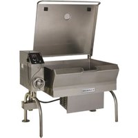
| Brand | Cleveland |
| Model | SEL-40-TR |
| Product Type | Tilting skillet |
| Capacity | 151 liters (40 gallons) |
| Material | Stainless steel |
| Lid | Yes, must be lifted before tilting |
| Tilt | Yes, manual or mechanical tilt |
| Power Supply | Electric or gas (depending on configuration) |
| Voltage / Frequency | 208-240 V / 60 Hz (electric) or natural gas/propane |
| Weight | Heavy, requires team or mechanical lifting |
| Main Functions | Cooking, braising, simmering, searing |
| Safety | Lockout/tagout of utilities before maintenance |
| Maintenance | Daily inspection, cleaning after use |
| Cleaning | Do not spray aerosols, avoid slippery spills |
| Spare Parts | Available through authorized technical service |
| Repairability | By qualified technician only |
| Installation | Must be anchored according to manual |
| Intended Use | Commercial foodservice use |
Frequently Asked Questions - SEL-40-TR Cleveland
User questions about SEL-40-TR Cleveland
0 question about this device. Answer the ones you know or ask your own.
Ask a new question about this device
Download the instructions for your Saucepan in PDF format for free! Find your manual SEL-40-TR - Cleveland and take your electronic device back in hand. On this page are published all the documents necessary for the use of your device. SEL-40-TR by Cleveland.
USER MANUAL SEL-40-TR Cleveland
TR Electric Braising Pan
Installation, Operation, Maintenance, Parts & Service
This manual is updated as new information and models are leased. Visit our website for the latest manual.
Models:
SEL-30-TR
SEL-40-TR
SEM-30-TR
SEM-40-TR
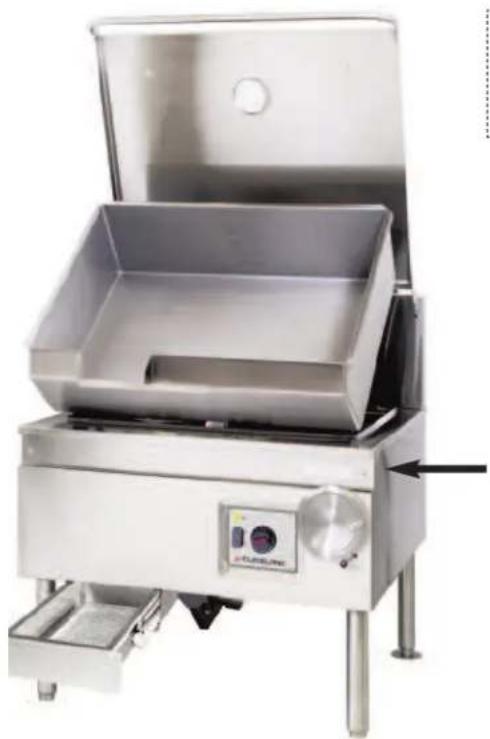
natural_image
Exterior view of a stainless steel industrial grater with control panel and side-mounted base (no visible text or symbols)For your future reference.
Model #
Serial #
Model # & Serial #.
(Open front panel to view rating label.)


Read the manual thoroughly.
Improper installation, operation or maintenance can cause property damage, injury or death.
TABLE OF CONTENTS
Statement of Responsibilities ....1
For your Safety 2
Installation 4
Operating Instructions 6
Cleaning Instructions 7
Preventative Maintenance 8
Trouble Shooting & Maintenance 9
Service Parts....10
This document is for use by experienced and trained Qualified Cleveland Range, LLC Authorized Service Representatives who are familiar with both the safety procedures, and equipment they service. Cleveland Range, LLC assumes no liability for any death, injury, equipment damage, or property damage resulting from use of, improper use of, or failure to use the information contained in this document. Cleveland Range, LLC has made every effort to provide accurate information in this document, but cannot guarantee that this document does not contain unintentional errors and omissions.
The information in this document may be subject to technical and technological changes, revisions, or updates. Cleveland Range, LLC assumes no liability or responsibility regarding errata, changes, revisions, or updates.
Qualified Cleveland Range, LLC Authorized Service Representatives are obligated to follow industry standard safety procedures, including, but not limited to, OSHA regulations, and disconnect / lock out / tag out procedures for all utilities including steam, and disconnect / lock out / tag out procedures for gas, electric, and steam powered equipment and / or appliances.
All utilities (gas, electric, water and steam) should be turned OFF to the equipment and locked out of operation according to OSHA approved practices during any servicing of Cleveland Range equipment
Qualified Cleveland Range, LLC Authorized Service Representatives are obligated to maintain up-to-date knowledge, skills, materials and equipment.
Do not store or use gasoline or any other flammable liquids and vapours in the vicinity of this or any other appliance.
POUR VOTRE SÉCURITÉ
WARNING: Improper installation, operation, adjustment, alteration, service or maintenance can cause property damage, injury or death. Read the installation and operating instructions thoroughly before installing, operating or servicing this equipment.
Do not spray aerosols in the vicinity of this appliance while it is in operation.
This appliance is not to be used by persons with reduced physical, sensory or mental capabilities, or lack of experience and knowledge, unless they have been given supervision or instruction concerning use of the appliance by a person responsible for their safety.
This appliance is not for use by children and they must be supervised not to play with it.
Retain this manual for your reference.
Installation of the unit must be accomplished by qualified installation personnel working to all applicable local and national codes.
This equipment is built to comply with applicable standards for manufacturers. Included among those approval agencies are: UL, A.G.A., NSF, ASME/N.Bd., CSA, CGA, ETL, and others. Many local codes exist, and it is the responsibility of the owner/installer to comply with these codes.
RECEIVING INSPECTION
Before unpacking visually inspect the unit for evidence of damage during shipping.
If damage is noticed, do not unpack the unit, follow shipping damage instructions.
SHIPPING DAMAGE INSTRUCTIONS
If shipping damage to the unit is discovered or suspected, observe the following guidelines in preparing a shipping damage claim.
- Write down a description of the damage or the reason for suspecting damage as soon as it is discovered. This will help in filling out the claim forms later.
- As soon as damage is discovered or suspected, notify the carrier that delivered the shipment.
- Arrange for the carrier's representative to examine the damage.
- Fill out all carrier claims forms and have the examining carrier sign and date each form.
APPROXIMATE WEIGHTS
| Model # Unit shipping | Unit with box |
| SEL-TR-30 420 lbs. 460 lbs. | |

UNCRATING
! CAUTION:
Straps under tension and will snap when cut. Carton may contain staples and skid contains nails. Use proper safety equipment and precautions. Unit is heavy. Use adequate help or lifting equipment as needed.

- Cut straps and remove box.
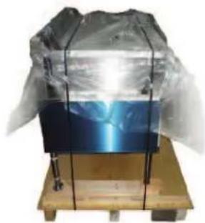
natural_image
Wooden table with a transparent plastic cover and a blue reflective panel, no visible text or symbols- Cut straps on unit.

3.
Remove screws from back of flanged feet (x6).
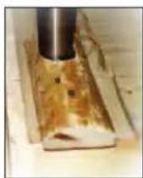
4.
Remove nails to free blocks on front legs.
VENTILATION
Operation of these units can produce significant levels of steam and condensate, it is recommended they be installed under a ventilation hood in a room which has provisions for adequate make up air. Further information can be obtained by referring to the U.S.A. National Fire Protection Associations NFPA96 regulations. These standards have also been adopted by the National
POSITIONING
This unit must be installed in accordance with the clearances shown on the rating label which is adhered to the unit.
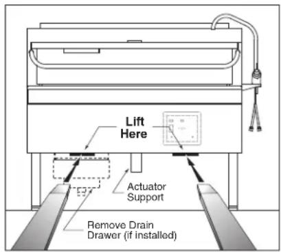
Caution:
The actuator is mounted in center of unit, if using a fork truck, lift as illustrated.
1 Position the unit in it's permanent location.
2. Level skillet by means of adjustable stainless steel feet. For your convenience a foot wrench is taped to one leg. Use a spirit level and level unit four ways; across front and back and down left and right edges.
3. Once positioned and leveled, permanently secure the unit's flanged feet to the floor using 5/16" lag bolts and floor anchors (supplied by the installer). Three bolts are required to secure each of the flanged feet.
4. Seal joints of flanged feet with a silicone sealant.
5. A protective material has been applied to the stainless steel panels. This material must be removed immediately after installation, as heat will melt the material and make it difficult to remove.
ELECTRICAL
Note: Ensure main power is turned off before connecting wires.
Note: The electrical rating label is located on the back the front panel. For easy access, remove the two screws securing the upper front panel and hinge the lower front panel downwards. Serial number, voltage, phase, amperage and wattage are stated on this label.
Wiring diagram is located on the bottom of component box cover.
ENSURE THE ELECTRICAL SUPPLY MATCHES THE UNIT'S REQUIREMENTS AS STATED ON THE ELECTRICAL RATING LABEL.
General Information
Install in accordance with local codes and/or the National Electric Code ANSI/NFPA No. 70-1990 (USA) or the Canadian Electric Code CSA Standard C22.1 (Canada). A separate fused disconnect switch must be supplied and installed. The unit must be electrically grounded by the installer.
The electrical supply must match the power requirements specified on the unit's rating label. The copper wiring must be adequate to carry the required current at the rated voltage. Wire must be suitable for at least 194°F (90°C). Refer to Specification Sheet for all electrical specifications. Cleveland strongly recommends the use of liquid tight fittings.
Connection
NOTE: The supply lines will enter through the rear (or bottom) of the unit near the left side of the skillet and are connected to the terminal block. For ease in attaching the supply lines there is a removable cover on the wiring compartment.
NOTE: This skillet is factory wired for a 3 phase installation. If single phase is required, check the wiring diagram for proper modifications. The wiring diagram is located on the back of the hinged front panel.
WATER (OPTIONAL)
A 1/2" NPT cold water line and/or a 1/2" NPT hot water line are required if unit is equipped with a single or double pantry faucet.
INSTALLATION CHECKS
Although the unit has been thoroughly tested before leaving the factory, the installer is responsible for ensuring the proper operation of unit once installed.
- Supply power to the unit by placing the fused disconnect switch to the "ON" position.
- Turn Temperature Dial to 150^ F ( 66^ C).
- Toggle Power Switch to the "ON" position.
- Heat Indicator Light (yellow) should be ON and unit heating. When temperature is reached, Yellow Indicator Light will switch OFF.
- Turn Temperature Dial to 300^ F ( 150^ C). Unit will continue to heat, Heat Indicator Light (yellow) will remain ON until temperature is reached. Then the heat indicator light will cycle off indicating the heating system has shut OFF. The heat indicator light will continue to cycle ON and OFF as the heating system cycles ON and OFF maintaining the desired temperature.
- Toggle Power Switch to the "OFF" position.
CLEANING
After installation the unit must be thoroughly cleaned and sanitized prior to cooking.
OPERATING INSTRUCTIONS


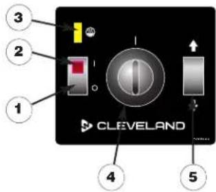
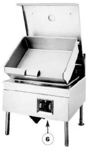
natural_image
Exterior view of a stainless steel industrial oven or processing unit with open lid and control panel (no visible text or symbols)# DESCRIPTION
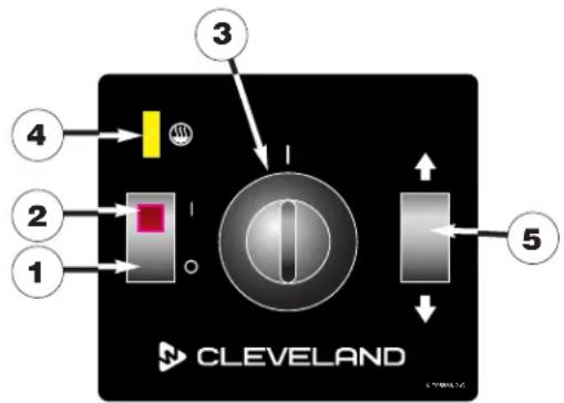
- On-Off Switch
- Power Indicator Light (Red)
- Heat Indicator Light (Yellow)
- Temperature Dial
- Power Tilt Switch
- Manual Tilt Override
- Tangent Draw-Off Valve (not shown)
- Faucet (not shown)

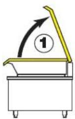
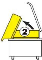
OPEN COVER
BEFORE
TILTING PAN
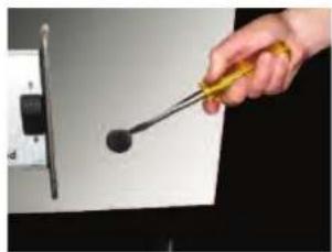
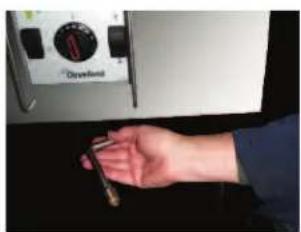
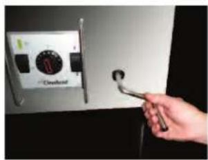
POWER TILT MANUAL OVERRIDE INSTRUCTIONS
NOTE: Once unit has been tilted there is now way to lower it until power is restored.
natural_image
Hand holding a screwdriver with a black screw, touching a wall-mounted device (no text or symbols visible)- Remove plug.
natural_image
Hand holding a small object next to a stainless steel appliance labeled 'Crylonel' (no other text or symbols visible)- Reach under skillet and remove tilt handle.
natural_image
Hand holding a wrench touching a wall-mounted control panel with 'Overload' label (no readable text beyond label)- Insert handle onto pump shaft and turn.
WARNING / AVERTISSEMENT / ADVERTENCIA
If for any reason this unit is not functioning correctly DO NOT OPERATE. Contact your autorized service agent.
OPERATING THE UNIT
- Perform daily startup inspection.
-
Turn Power Switch to the ON position. The yellow Heat Indicator Light will indicate pan is heating.
-
MANUAL TILT: To raise pan, raise the cover and turn the crank clockwise. To lower pan, turn counterclockwise.
POWER TILT: To raise pan, raise the cover and press up on the tilt switch. To lower pan, press down on the tilt switch.

FOR YOUR SAFETY: A power interrupter will automatically shut of the power to the elements whenever the skillet is raised more than 1/2" (13mm).
IMPORTANT: Before commencing to cook, ensure pan is in the lowered position.
- To preheat, set Temperature Dial to desired cooking temperature.
- Allow skillet to preheat for approximately 15-30 minutes.
- Once preheated, insert product in skillet and adjust Temperature Dial to required cooking temperature.
- If desired, once product has cooked, it can be held prior to serving at a lower temperature setting.
- When cooking is completed, set Temperature Dial and Power Switch to the OFF position.
- Pour the contents of the unit into an appropriate container by tilting the kettle forward or using discharge valve.

NOTE: Cleaning should be completed immediately after cooked foods are removed.
OPERATING SUGGESTIONS
- Turn power switch to the "OFF" position when skillet is not in use.
- Allow skillet to preheat before adding product.
- Always lift the spring assist cover before activating the tilt mechanism.
- During an electrical power interruption, turn Power Switch to the OFF position. This unit cannot be made to operate without electrical power.
CLEANING INSTRUCTIONS



CARE AND CLEANING
Cooking equipment must be cleaned regularly to maintain its fast, efficient cooking performance and to ensure its continued safe, reliable operation. The best time to clean is shortly after each use (allow unit to cool to a safe temperature).
WARNINGS

Chloride Cleaners
Do not use detergents or cleansers that are chloride based or contain quaternary salt.

Wire Brush & Scrapers
Do not use a metal bristle brush or scraper.

Steel Pads
Steel wool should never be used for cleaning the stainless steel.
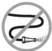
High Pressure Spray Hose
Unit should never be cleaned with a high pressure spray hose.

Stagnant Water
Do not leave water sitting in unit when not in use.
CLEANING INSTRUCTIONS
- Turn unit off.
- Remove drain screen (if applicable). Thoroughly wash and rinse the screen either in a sink or a dishwasher.
- Prepare a warm water and mild detergent solution in the unit.
- Remove food soil using a nylon brush.
- Loosen food which is stuck by allowing it to soak at a low temperature setting.
- Drain unit.
- Rinse interior thoroughly.
- If the unit is equipped with a Tangent Draw-Off Valve, clean as follows:
a) Disassemble the draw-off valve first by turning the valve knob counterclockwise, then turning the large hex nut counter-clockwise until the valve stem is free of the valve body.
b) In a sink, wash and rinse the inside of the valve body using a nylon brush.
c) Use a nylon brush to clean tangent draw-off tube.
d) Rinse with fresh water.
e) Reassemble the draw-off valve by reversing the procedure for disassembly. The valve's hex nut should be hand tight only.
- Using mild soapy water and a damp sponge, wash the exterior, rinse, and dry.
NOTES
For more difficult cleaning applications one of the following can be used: alcohol, baking soda, vinegar, or a solution of ammonia in water.
→Leave the cover off when the kettle is not in use.
For more detailed instructions refer to Stainless Steel Equipment Care and Cleaning (www.nafem.org/resources/stainlesssteelfinal.doc) on Nafem's website (www.nafem.org).
natural_image
Pure electrical circuit lines without any symbolsDISPOSAL INSTRUCTIONS
This unit is recyclable. Do not dispose in landfill.
The majority of the unit is composed of stainless steel. Other alloys and electrical components make up a small percentage of the total. Follow Federal, state and local regulations for disposal.
PREVENTATIVE MAINTENANCE

FOR MAINTENANCE AND REPAIRS CONTACT YOUR AUTHORIZED MANITOWOC SERVICE AGENCY AND HAVE A QUALIFIED SERVICE TECHNICIAN MAINTAIN YOUR EQUIPMENT.


Cleveland Range equipment requires little preventative maintenance.
We do however provide the following guidelines for inspection and maintenance to keep your unit functioning at 100%.

DAILY PRE-STARTUP INSPECTION
- Cover tilts up and down freely and is held in place when fully open.
- Draw-Off Valve (if equipped) is installed and handle is in place.
- Tilt hand wheel is tight (if equipped).
- Tilt switch (if equipped) (5) is not broken and is functioning properly.
- Pan tilts up and down correctly.
- Temperature dial (3) is in place and functioning properly.
- Red Light (2) comes on when unit is turned on.
- Orange Light (4) is on when unit is heating.
- Orange Light (4) is off when unit is tilted.
WARNING:

If for any reason this unit is not functioning correctly DO NOT OPERATE. Contact your authorized service agent.
SIX MONTH SERVICE INSPECTION
- Perform daily startup inspection.
- There are no hydraulic oil leaks.
- Adequate exhaust and makeup air is supplied to working area.
- All panels are in place and securely fastened.
YEARLY SERVICE INSPECTION
- Perform six month service inspection.
- Inspect safety thermostat for proper connections.
- Clean blower.
- Perform free air calculation (see FREE AIR CACULATION).
TROUBLESHOOTING AND MAINTENANCE PROCEDURES
The following trouble shooting guide and maintenance procedures are meant to be used by Qualified Service Technician




For periodic maintenance recommendations see "Operators Manual".
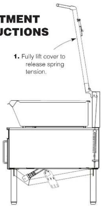
HINGE
ADJUSTMENT
INSTRUCTIONS
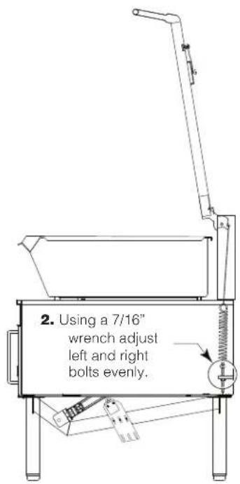
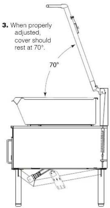
CALIBRATION INSTRUCTIONS
IMPORTANT: DO NOT ATTEMPT TO CALIBRATE THE THERMOSTAT
The electronic thermostat supplied with this skillet has been precisely calibrated at the factory and should not require field calibration.
RECOMMENDED SPARE PARTS LIST
ITEM ON. DESCRIPTION QTY.
KE55069-7 SAFETY THERMOSTAT 1
SK50905-2 LIGHT 1
KE52936-13 FUSE, 1 AMP, 250V 1
SK2498399 SHAFT ASSEMBLY, POTENTIOMETER 1
SK2474100 SWITCH, OP/OFF, 120V 1
KE603902-7 CONTACTOR 2
SK53838-30 TRANSFORMER 1
SK2343502 SWITCH, POWER TILT 1
KE52936-9 FUSE, 15 AMP, 250 V 1
SK2345100 THERMOSTAT SENSOR 1
SK2142002 TEMPERATURE SENSOR BOARD 1
SERVICE PARTS
WARRANTY
Our Company supports a worldwide network of Maintenance and Repair Centers. Contact your nearest Maintenance and Repair Centre for replacement parts, service, or information regarding the proper maintenance and repair of your cooking equipment.
In order to preserve the various agency safety certification (UL, NSF, ASME/Ntl. Bd., etc.), only factory-supplied replacement parts should be used. The use of other than factory supplied replacement parts will void warranty.
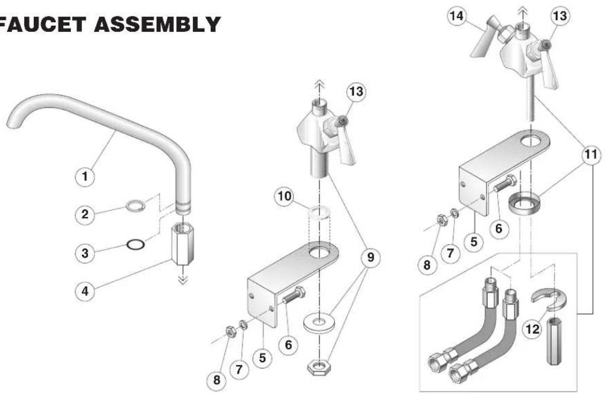
ITEM # PART # DESCRIPTION QTY.
SPK14 SINGLE PANTRY FAUCET (includes items 1-10)
DPK14 DOUBLE PANTRY FAUCET (includes items 1-8 & 11)
-
KE50825-6 3/4" SPOUT 1
-
FA95007-10 RETAINING RING 1
-
FA05002-19 'O' RING 1
-
KE51736 LONG FAUCET NUT 1
-
SK2382300 FAUCET MOUNTING BRACKET 1
SK2382400 SPACER, FOR BRACKET 1
-
FA11258 HEX CAP SCREW 2
-
FA31029 LOCK WASHER 2
-
FA21008 HEX NUT 2
-
KE51401 SINGLE PANTRY BODY (c/w item 13) 1
-
KE50335 ADAPTER WASHER 1
-
KE51403 DOUBLE PANTRY BODY (c/w item 13 & 14) 1
-
SE50447 REPLACEMENT HORSESHOE WASHER 1
-
SE50021 REPLACEMENT STEM ASSEMBLY, COLD WATER 1
-
SE50020 REPLACEMENT STEM ASSEMBLY, HOT WATER 1
POWER TILT ASSEMBLY
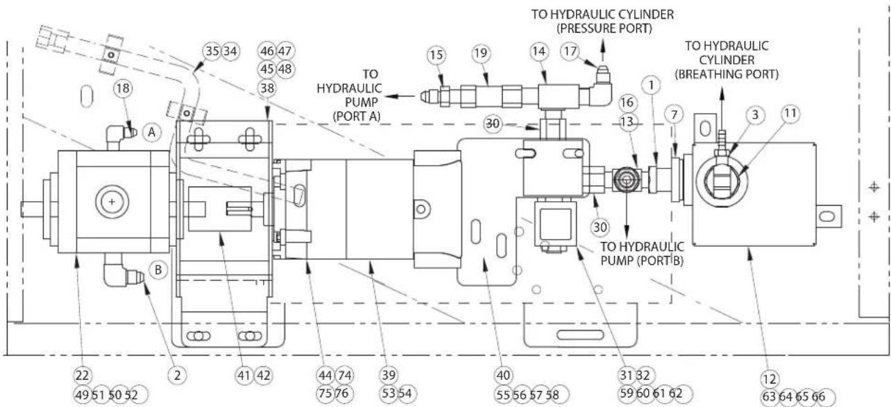
| ITEM | PART # | DESCR | PTION | QTY. |
| 1 | FI00351 | HEX | BUSHING; 1/2 X 1/4 1 | |
| 2 | FI05059 | ELBOW; | STRAIGHT THREAD 1 | |
| 3 | FI05318-1 | ELBOW | HOSE BARB 90 BRASS 1 | |
| 4 | KE000523 | HYDRAULIC | JACK ASSY TR/F | |
| 5 | KE53143 | PLUG; 1/4-18 | HYDRAULIC | 1 |
| 6 | KE55267 | FLOW | RESTRICTOR MT/TR | 1 |
| 7 | KE600452 | STRAINER; OIL (MT-TR/F) | 1 | |
| 8 | KE603728 | COVER; CONTROL SWITCHES | 1 | |
| 9 | M194 | HYDRAULIC OIL; HD68-4L | 1 | |
| 10 | SK2147401 | FITTING; LIQUID TIGHT | 1 | |
| 11 | SK2250700 | PLUG MODIFD FI00285 | 1 | |
| 12 | SK2375699 | OIL TANK ASSY MT/TR | 1 | |
| 13 | SK2378900 | TEE; 1/4 P (M/F/M) | 1 | |
| 14 | SK2378901 | TEE; 1/4 P (F/M/M) | 1 | |
| 15 | SK2379000 | ADAPTER; 1/4 P | 1 | |
| 16 | SK2379001 | ADAPTER; 1/4 P | 1 | |
| 17 | SK2379100 | ELBOW; 1/4-90D- | 2 | |
| 18 | SK2379200 | ELBOW; ORING BOSS 90DEG | 1 | |
| 19 | SK2379400 | CHECK VALVE PARKER C400B | 1 | |
| 21 | KE95586-2 | LABEL; CLEVELAND/PT/TR | 1 | |
| 22 | SK2378802 | HYDRAULIC PUMP; TR/F | 1 | |
| 23 | SK2379501 | HYDRAULIC HOSE ASSY;22 | 2 | |
| 24 | KE50581 | BRIDGE RECTIFIER; #MB256 1 | ||
| 25 | KE52936-9 | FUSE; 15A/250V/MDA-15-R | 1 | |
| 26 | SK1427305 | CAPACITOR;4700MF/63VDC | 1 | |
| 27 | SK2282100 | CAPACITOR; CLAMP #VR3 | 1 | |
| 28 | SK2343502 | SWITCH; TILT SWITCH | 1 | |
| 29 | KE601979 | LIMIT SW ;TR- (UL APPV ) | 1 | |
| 30 | KE603895 | HYDRAULIC HOSE ADAPTER | 2 | |
| 31 | KE54834-17 | SOLENOID VALVE | 1 | |
| 32 | KE603873 | SOLENOID VALVE CONNECTOR | 1 | |
| 33 | KE003707 | HYDRAULIC HOSE ASSY | 1 | |
| 34 | KE003160 | HANDLE MANUAL CRANK | 1 | |
| 35 | SK2473800 | CLIP; SMALL | 2 | |
| 36 | F10 | PAN QUAD SCR #8-32X3/8 | 2 | |
| 37 | KE54907-1 | PLUG BUTTON | 1 | |
| 38 | KE003705 | MOTOR MOUNT BRACKET ASSY | 1 | |
| 39 | KE603896 | GEARMOTOR, DC | 1 | |
| 40 | KE603898 | SOLENOID MOUNTING PLATE | 1 | |
| 41 | KE50582-5 | COUPLING HUB 1/2 DIA. | 2 | |
| 42 | KE50583-1 | SPIDER | 1 | |
| 43 | SK2147402 | LIQUID TIGHT FITTING | 1 | |
| 44 | KE603951 | GEAR MOTOR COVER | 1 | |
| ITEM | PART # | DESCRIPTION | QTY. |
| FASTENERS FOR THE MOTOR MOUNT BRACKET ASS'Y | |||
| 45 | FA11260 | HEX BOLTS S.S., 1/4-20UNC X 1" | 4 |
| 46 | FA30505-1 | FLAT WASHER S.S, 1/4 | 8 |
| 47 | FA31029 | LOCK WASHER S.S., 1/4 | 4 |
| 48 | FA21008 | HEX NUT S.S., 1/4-20UNC | 4 |
| FASTENERS FOR THE HYDRAULIC PUMP | |||
| 49 | FA11325 | HEX BOLTS S.S., 15/16-18UNC X 1 1/4" | 2 |
| 50 | FA30505-5 | FLAT WASHER S.S, 5/16 | 2 |
| 51 | FA31030 | LOCK WASHER S.S., 5/16 | 2 |
| 52 | FA21024 | HEX NUT S.S., 5/16-18UNC | 2 |
| FASTENERS FOR GEARMOTOR | |||
| 53 | FA11148 | 10-32UNF X 3/4 PAN PHIL M/S 18-8 S.S. | 4 |
| 54 | FA32022 | EXT. TOOTH LOCK WASHER S.S, #10 | 4 |
| FASTENERS FOR SOLENOID MOUNTING PLATE | |||
| 55 | FA11260 | HEX BOLTS S.S., 1/4-20UNC X 1" | 2 |
| 56 | FA30505-1 | FLAT WASHER S.S, 1/4 | 4 |
| 57 | FA31029 | LOCK WASHER S.S., 1/4 | 2 |
| 58 | FA21008 | HEX NUT S.S., 1/4-20UNC | 2 |
| FASTENERS FOR SOLENOID VALVE | |||
| 59 | FA11509-4 | HEX BOLTS S.S., 1/4-20UNC X 1 3/4" | 2 |
| 60 | FA30505-1 | FLAT WASHER S.S, 1/4 | 4 |
| 61 | FA31029 | LOCK WASHER S.S., 1/4 | 2 |
| 62 | FA21008 | HEX NUT S.S., 1/4-20UNC | 2 |
| FASTENERS FOR TANK | |||
| 63 | FA11148 | 10-32UNF X 3/4 PAN PHIL M/S 18-8 S.S. | 1 |
| 64 | FA32022 | EXT. TOOTH LOCK WASHER S.S, #10 | 1 |
| 65 | FA30505-2 | FLAT WASHER S.S., #10 | 1 |
| 66 | FA21006 | HEX NUTS 18-8 S.S, #10-24UNC | 1 |
| FASTENERS FOR TILTING LIMIT SWITCH | |||
| 67 | FA11148 | 10-32UNF X 3/4 PAN PHIL M/S 18-8 S.S. | 2 |
| 70 | FA30505-9 | SAE FLAT WASHERS S.S, 1/4 | 2 |
| 71 | FA31029 | LOCK WASHERS 18.8, 1/4 | 2 |
| 73 | FA11260 | HEX BOLTS S.S., 1/4-20UNC X 1" | 2 |
| PAN WITH TD OPTION | |||
| 72 | KE603877-1 | LIMIT SWITCH MOUNTING BRACKET | 1 |
| PAN WITHOUT TD OPTION | |||
| 72 | KE603877-2 | LIMIT SWITCH MOUNTING BRACKET | 1 |
| TO ORDER COMPLETE ASSEMBLY: | |||
| 72 | SK003706-1 | FOR UNITS WITH TD OPTION | 1 |
| 72 | SK003706-3 | FOR UNITS WITH OUT TD OPTION | 1 |
ITEMS 4, 5, 6, 7, 8, 9, 10, 21, 23, 24, 25, 26, 27, 28, 29, 33, 36, 37, 43, 67, 70, 71, 72 & 73 NOT SHOWN
MANUAL TILT ASSEMBLY
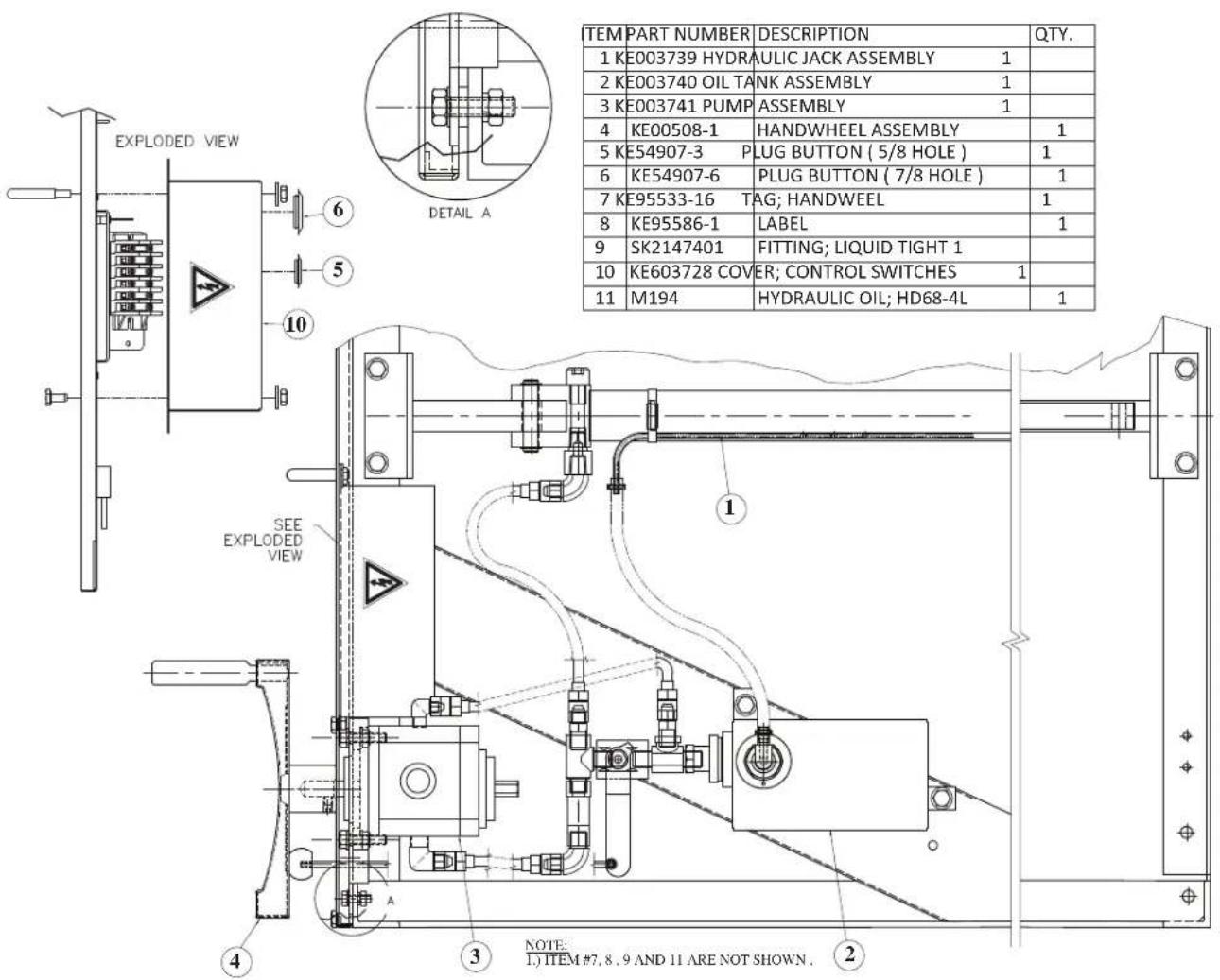
KE003746
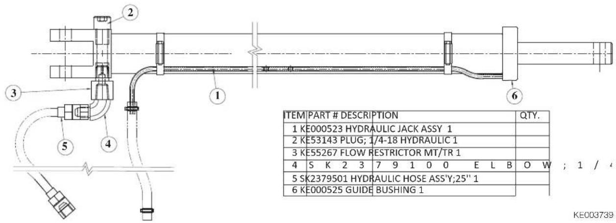
HYDRAULIC JACK ASSEMBLY
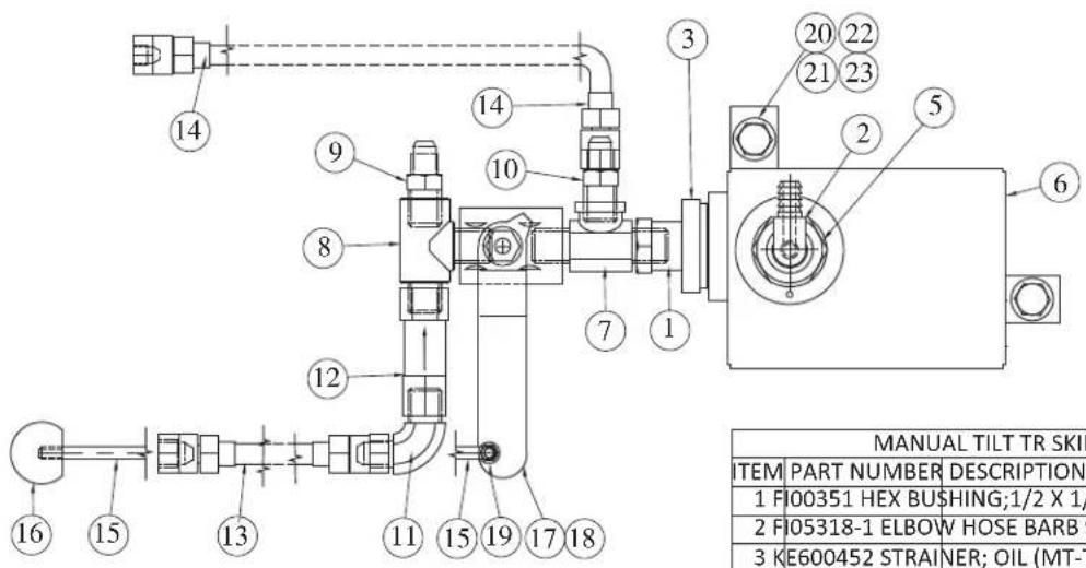
OIL TANK ASSEMBLY
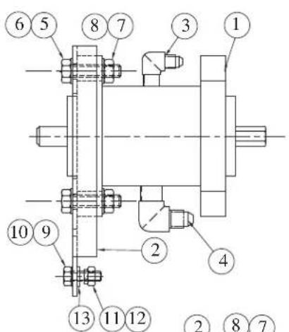
PUMP ASSEMBLY
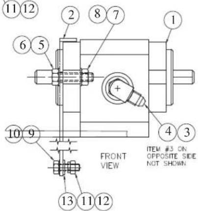
| MANUAL TILT TR SKILLET ASSEMBLY | |||
| ITEM | PART NUMBER | DESCRIPTION | QTY. |
| 1 | F00351 HEX BUSHING;1/2 X 1/4 1 | ||
| 2 | F05318-1 ELBOW HOSE BARB 90 BRASS 1 | ||
| 3 | KE600452 STRAINER; OIL (MT-TR/F) 1 | ||
| 5 | SK2250700 PLUG MODIFD FIO0285 1 | ||
| 6 | SK2375699 OILTANK ASSY MT/TR 1 | ||
| 7 | SK2378900 TEE; 1/4 P (M/F/M) 1 | ||
| 8 | SK2378901 TEE; 1/4 P (F/M/M) 1 | ||
| 9 | SK2379000 ADAPTER; 1/4 P 1 | ||
| 10 | SK2379001 ADAPTER; 1/4 P 1 | ||
| 11 | SK2379100 ELBOW;1/4-90D- 1 | ||
| 12 | SK2379400 CHECK VALVE PARKER C400B 1 | ||
| 13 | SK2379500 HYDRAULIC HOSE ASS'Y;8" | 1 | |
| 14 | SK2379600 HYDRAULIC HOSE ASS'Y. | 1 | |
| 15 | SK2376200 LINK ROD | 1 | |
| 16 | SK078279-1 BALL KNOB | 1 | |
| 17 | SK2379301 BALL VALVE | 1 | |
| 18 | SK2382700 VA VE RETURN SPRING | 1 | |
| 19 | FA20504-3 LOCK NUT #10 | 1 | |
| 20 | FA11260 HEX BOLT S.S. 1/4-20 X 1 | 2 | |
| 21 | FA30505-1 FLAT WASHER S.S 1/4 | 2 | |
| 22 | FA31029 LOCK WASHER S.S 1/4 | 2 | |
| 23 | FA21008 HEX NUT S.S 1/4 | 2 | |
KE003740
KE003741
| ITEM | PART NUMBER | DESCRIPTION QTY. | |
| 1 | SK2378802 HY | DRAULIC PUMP; TR/F | 1 |
| 2 | SK2376000 PU | MP MOUNT BRACKET 1 | |
| 3 F | 05059 E | BOW; STRAIGHT THREAD | 1 |
| SK2379200 ELB | OW;O'RING BOSS 90DEG | 1 | |
| 5 | FA11325 | HEX BOLT S.S. 5/16-18 X 1 1/4 | 2 |
| 6 | FA30505-5 | FLAT WASHER S.S 5/16 | 2 |
| 7 | FA21024 | HEX NUT S.S. 5/16-18 | 2 |
| 8 | FA31030 | SPLIT LOCKWASHER S.S 5/16 | 2 |
| 9 | FA11260 HEX B | BOLT S.S. 1/4-20 X 1 | 3 |
| 10 | FA30505-1 | FLAT WASHER S.S 1/4 | 3 |
| 11 | FA31029 | LOCK WASHER S.S 1/4 | 3 |
| 12 | FA21008 | HEX NUT S.S 1/4 | 3 |
| 13 | FA30504 | FLAT WASHER 0.328 X 0.625 | 3 |
OIL TANK ASSEMBLY
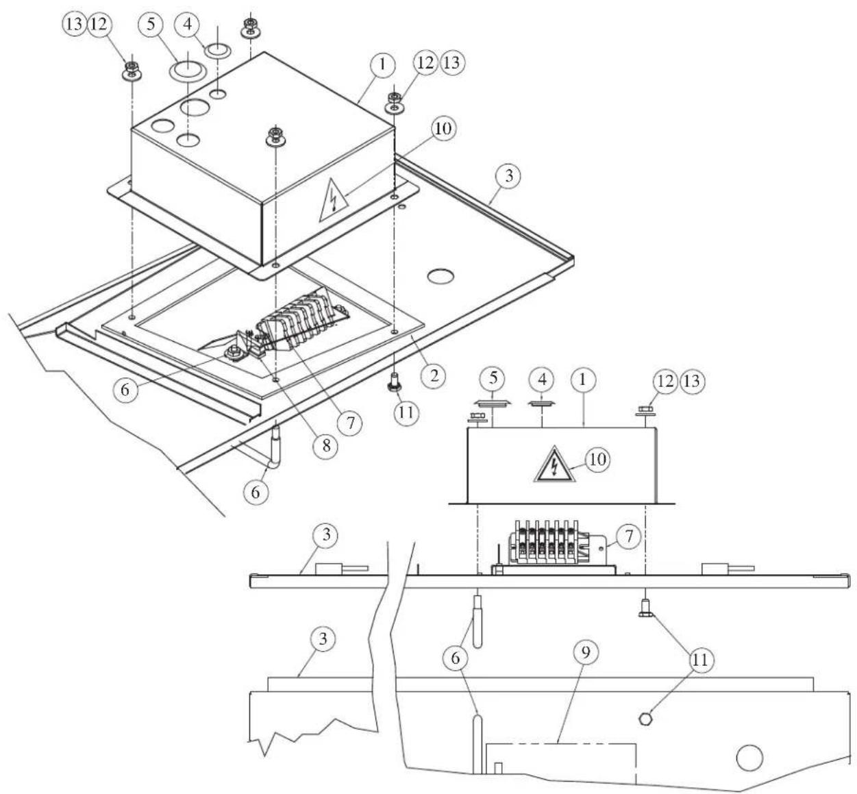
KE003742
| KE003742-1 PANEL ASSEMBLY SGL-30-TR | |||
| ITEM | PART NUMBER | DESCRIPTION | QTY. |
| 1 | KE603728 | COVER; CONTROL SWITCHES | 1 |
| 2 | KE603729 | GASKET | 1 |
| 3 | SK00383-4 | CONTROL PANEL ASS'Y 30 GAL | 1 |
| 4 | KE54907-3 | PLUG BUTTON ( 5/8 HOLE ) | 1 |
| 5 | KE54907-6 | PLUG BUTTON ( 7/8 HOLE ) | 1 |
| 6 | KE601005 | SWITCH GUARD | 1 |
| 7 | KE603726 | TERMINAL BLOOCK BRACKET | 1 |
| 8 | SK50905-1 | 28V INDICATOR CLEAR LIGHT | 1 |
| 9 | KE95586-1 | LABEL; TR SKILLETS | 1 |
| 10 | KE95497 | LABEL; RISK OF EL. SHOCK | 1 |
| 11 | FA11260 | HEX BOLT S.S. 1/4-20 X 1 | 2 |
| 12 | FA30505-1 | FLAT WASHER S.S 1/4 | 4 |
| 13 | FA21008 | HEX NUT S.S 1/4 | 4 |
| 14 | FA20504-3 | LOCK NUT #10 | 2 |
| KE003742-2 PANEL ASSEMBLY SGL-40-TR | |||
| ITEM | PART NUMBER | DESCRIPTION | QTY. |
| 1 | KE603728 | COVER; CONTROL SWITCHES | 1 |
| 2 | KE603729 | GASKET | 1 |
| 3 | SK00383-3 | CONTROL PANEL ASS'Y 40 GAL | 1 |
| 4 | KE54907-3 | PLUG BUTTON ( 5/8 HOLE ) | 1 |
| 5 | KE54907-6 | PLUG BUTTON ( 7/8 HOLE ) | 1 |
| 6 | KE601005 | SWITCH GUARD | 1 |
| 7 | KE603726 | TERMINAL BLOOCK BRACKET | 1 |
| 8 | SK50905-1 | 28V INDICATOR CLEAR LIGHT | 1 |
| 9 | KE95586-1 | LABEL; TR SKILLETS | 1 |
| 10 | KE95497 | LABEL; RISK OF EL. SHOCK | 1 |
| 11 | FA11260 | HEX BOLT S.S. 1/4-20 X 1 | 2 |
| 12 | FA30505-1 | FLAT WASHER S.S 1/4 | 4 |
| 13 | FA21008 | HEX NUT S.S 1/4 | 4 |
| 14 | FA20504-3 | LOCK NUT #10 | 2 |
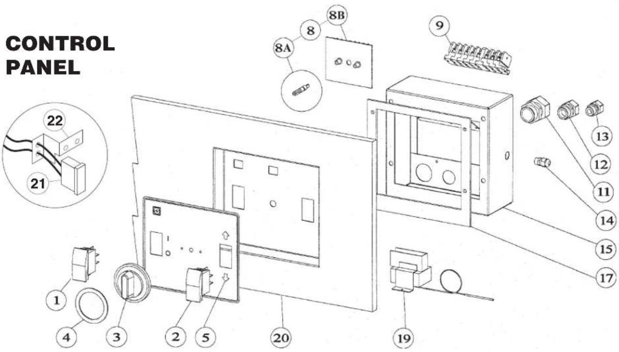
ITEM NO. PART NO. DESCRIPTION QTY.
1 SK2474101 POWER SWITCH 1
2 SK2343502 TILT SWITCH (POWER TILT ONLY) 1
3 SK2138700 DIAL KNOB 1
4 SK2360701 DIAL INSERT °C 1
SK2360700 DIAL INSERT °F 1
5 SKKE95586-1 LABEL, CLEVELAND, MANUAL TILT 1
KE95586-2 LABEL, CLEVELAND, POWER TILT 1
8 SE00119 ELECTRONIC THERMOSTAT KIT (INCLUDES 8A & 8B) 1
8A SK2142002 ELECTRONIC THERMOSTAT 1
8B SK2498399 SHAFT ASSY. 1
9 SK50872-1 TERMINAL BLOCK 16
SK50872-2 TERMINAL END 3
KE603726 TERMINAL BLOCK BRACKET 1
11 SK2147403 LIQUID-TIGHT FITTING 5/8" 1
12 SK2147402 LIQUID-TIGHT FITTING 3/8"
13 SK2147401 LIQUID-TIGHT FITTING 5/16" (POWER TILT ONLY) 1
14 SK2147400 LIQUID-TIGHT FITTING 3/16"
15 KE603728 COVER, CONTROL SWITCHES 1
17 KE603729 NEOPRENE GASKET 1
19 KE55069-7 HIGH LIMIT 1
20 SK00383-1 CONTROL PANEL, POWER TILT, 40-TR 1
SK00383-2 CONTROL PANEL, POWER TILT, 30-TR
SK00383-3 CONTROL PANEL, MANUAL TILT, 40-TR 1
SK00383-4 CONTROL PANEL, MANUAL TILT, 30-TR 1
21 SK50905-2 INDICATOR LIGHT (ELECTRIC MODELS) 1
22 SK50903-1 BRACKET 1
SHAFT ASSEMBLY
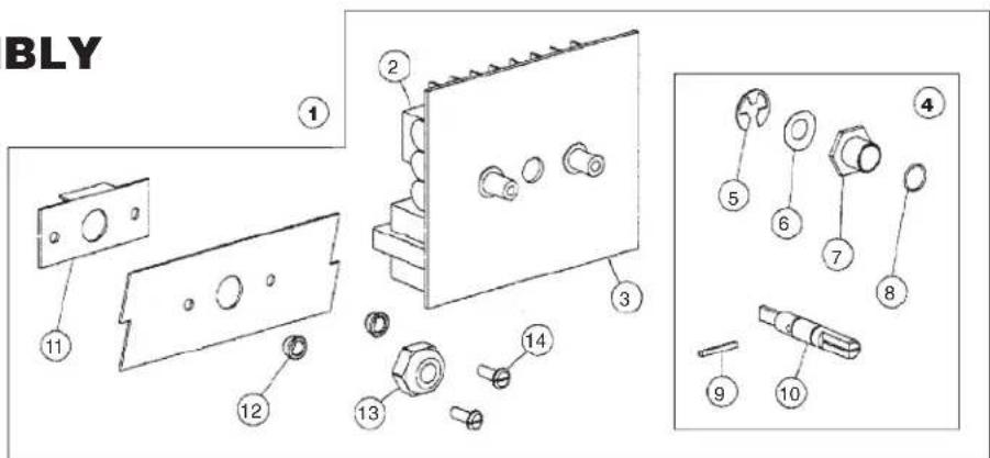
ITEM NO. PART NO. DESCRIPTION QTY.
-
SE00119 THERMOSTAT BOARD ASSEMBLY (INCLUDES 2 - 14) 1
-
SK2142002 TEMPERATURE SENSOR BOARD 1
-
SK2159300 INSULATOR, THERMOSTAT 1
-
SK2498399 POTENTIOMETER SHAFT ASSEMBLY (INCLUDES 5-10) 1
-
SK2167200 RETAINING RING, SP-NR #R1000-25 1
-
SK2167100 WASHER, BOWED/SPRING 1
-
SK2167300 PANEL BEARING 1
-
SK2382800 RETAINING RING CLIP 1
-
SK2167000 TENSION PIN 1
-
SK2166800 POTENTIOMETER SHAFT 1
-
SK2491500 STOP PLATE ASSY. 1
-
KE55242-2 SEALER WASHER 2
-
KE51005 ROTARY SHAFT SEAL 1
-
FA11056 SCREW 6-32 X 1/8 2
PAN HINGE
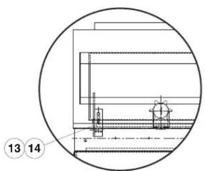
For units with TD Valve
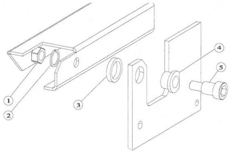
ITEM NO. PART NO. DESCRIPTION QTY.
1 FA20032 LOCK NUT 1/2-13 S.S. ....2
2 FA30505-3 LOCK WASHER 1/2-13 S.S. 2
3 SK078248-1 SPACER 2
4 G02925-2 BUSHING 2
5 FA15015 BOLT 1/2-13 X 3/4", for units with TD .....2
13 FA15019-2 SHOULDER BOLT, 1/2-13 (303) .....2
14 SK50813 BEARING HINGE 2
FRAME / LID ASSMEBLY
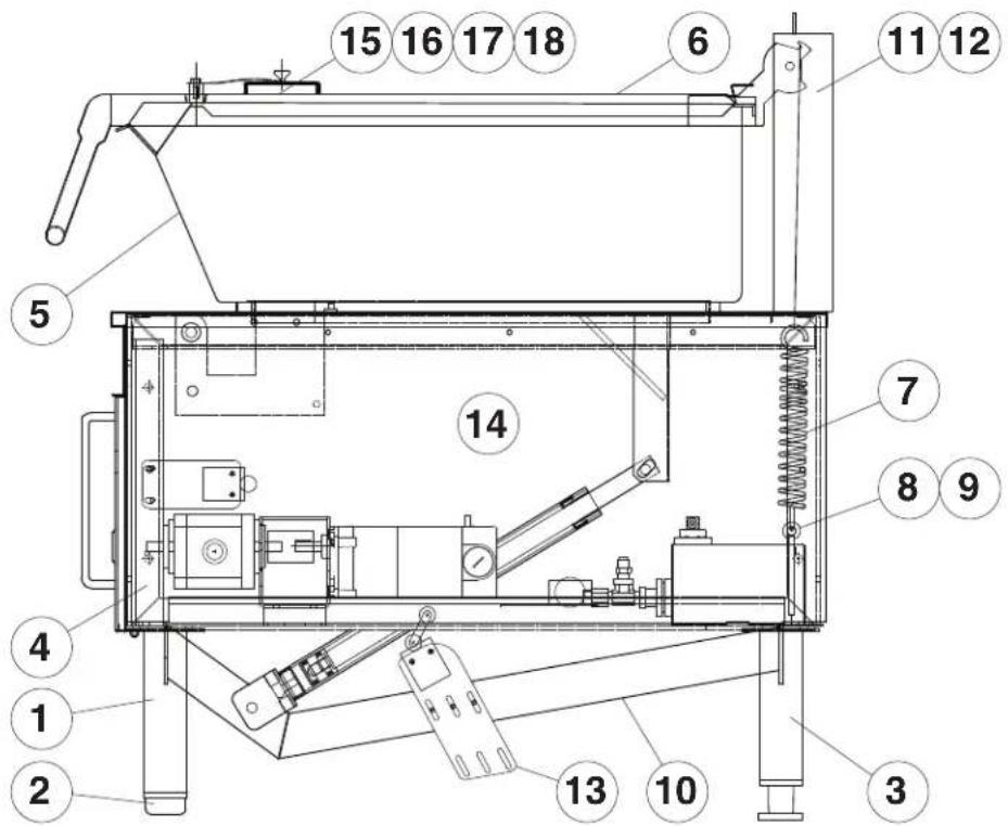
ITEM NO. PART NO. DESCRIPTION QTY.
- SK2335499 LEG ASSEMBLY, FRONT 2
- SK078160-1 FEET, FRONT 2
- SK00414-1 LEG ASSEMBLY, REAR 2
-
SK2335199 FRAME WELDMENT, 30 GAL. 1 SK2335099 FRAME WELDMENT, 40 GAL. 1
-
SK00343-1 PAN WELDMENT, SEL-30 (add -2 for units with TD) SK00344-1 PAN WELDMENT, SEL-40 (add -2 for units with TD) ..... 1
-
SK24571-1 LID, 30 GAL....1 SK24571-2 LID, 40 GAL....1
-
SK2452300 SPRING 2
-
KE003686 HOOK WELDMENT 2
-
SK23724-1 HOOK 2
-
SK2337499 ACTUATOR MOUNTING BRACKET 1 SK00352 ACTUATOR MOUNTING BRACKET, for units with TD 1
-
KE003605-1 BACKGUARD ASSEMBLY, 30 GAL. 1
KE003605 BACKGUARD ASSEMBLY, 40 GAL. 1 SK2389300 BACKGUARD BACK, 30 GAL. 1
SK2389301 BACKGUARD BACK, 40 GAL. 1
-
KE002206 LIMIT SWITCH BRACKET 1 KE002199 LIMIT SWITCH BRACKET, for units with TD 1
-
SK2336800 SIDE PANEL, SEL/SGL 2 SK2336801 SIDE PANEL, SEM/SGM 2
-
SK00054 VENT COVER ASSEMBLY 1
-
SK2211200 SPACER 1
-
FA95081-1 BOLT, MODIFIED 1
-
SK50179 WASHER 1
ELECTRICAL BOX
POWER TILT
MAMUAL TILT
natural_image
Interior view of an open electronic device with exposed wiring and components (no visible text or symbols)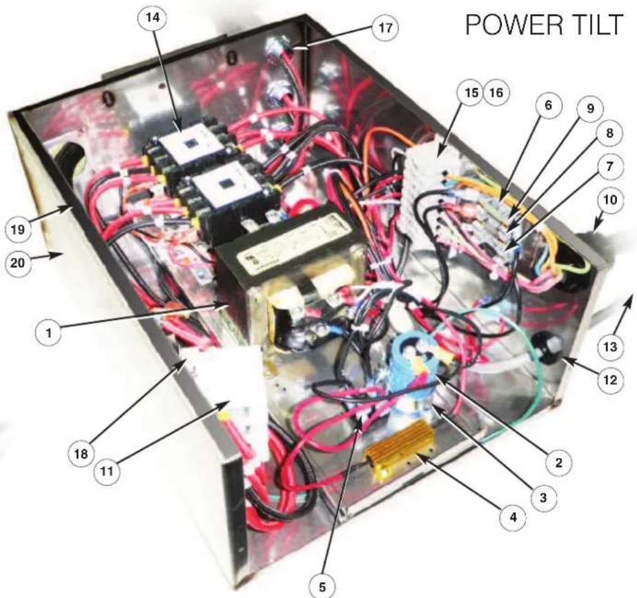
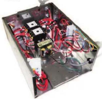
ITEM NO. PART NO. DESCRIPTION QTY.
1 KE53838-31 TRANSFORMER - POWER TILT, 208 - 480V ..... 1
KE53838-30 TRANSFORMER - POWER TILT, 220 - 415V ..... 1
KE53838-33 TRANSFORMER - HAND TILT, 208 - 480V .....1
KE53838-15 TRANSFORMER - HAND TILT, 220 - 415V ..... 1
2 SK1427305 CAPACITOR - POWER TILT 1
3 SK2282100 CAPACITOR CLAMP - POWER TILT 1
4 SK1426600 RESISTOR - POWER TILT 1
5 KE50581 RECTIFIER - POWER TILT 1
6 SK2320702 FUSE HOLDER 1
7 KE52936-10 FUSE 1.5A/250V - POWER TILT, 208 - 240V 1
KE52936-11 FUSE 0.5A/250V - HAND TILT, 208 - 240V 1
8 KE52936-13 FUSE 1A AGC - POWER & HAND TILT 1
9 KE52936-9 FUSE 15A MDA - POWER TILT ONLY 1
10 SK2147403 LIQUID-TIGHT FITTING 5/8" 1
11 KE50377 TERMINAL BLOCK 3
KE50376 TERMINAL END 1
12 SK2147401 LIQUID-TIGHT FITTING 5/16" 1
13 KE002226 INTERRUPTER SWITCH 1
14 KE603902-7 CONTACTOR 3 POLE 2
15 SK50872-1 TERMINAL BLOCK - JUNCTION 16
16 SK50872-2 TERMINAL END 2
17 SK50399 1/2" LIQUID-TIGHT CONNECTOR STRAIGHT ....3
18 SK2347300 TERMINAL BLOCK SUPPORT 1
19 SK2383400 COVER GASKET 1
20 SK2372099 SERVICE BOX ASSY. 1
PAN
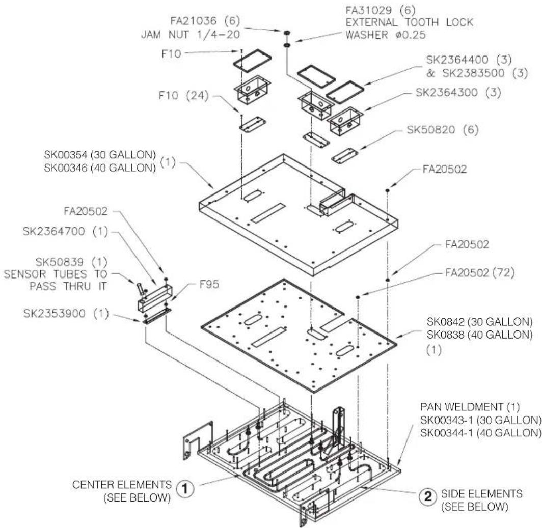
ITEM NO. PART NO. DESCRIPTION QTY.
| 1. (SEL/SEM-30-TR) | 2356306 | ELEMENT - CENTER, 4.8KW, 600V. | 1 |
| 2356305 | ELEMENT - CENTER, 4.8KW, 480V. | 1 | |
| 2356304 | ELEMENT - CENTER, 4.8KW, 415V. | 1 | |
| 2356303 | ELEMENT - CENTER, 4.8KW, 380V. | 1 | |
| 2356302 | ELEMENT - CENTER, 4.8KW, 240V. | 1 | |
| 2356301 | ELEMENT - CENTER, 4.8KW, 220V. | 1 | |
| 2356300 | ELEMENT - CENTER, 4.8KW, 208V. | 1 | |
| 2. (SEL/SEM-30-TR) | 2373006 | ELEMENT - SIDE, 4.8KW, 600V. | 2 |
| 2373005 | ELEMENT - SIDE, 4.8KW, 480V. | 2 | |
| 2373004 | ELEMENT - SIDE, 4.8KW, 415V. | 2 | |
| 2373003 | ELEMENT - SIDE, 4.8KW, 380V. | 2 | |
| 2373002 | ELEMENT - SIDE, 4.8KW, 240V. | 2 | |
| 2373001 | ELEMENT - SIDE, 4.8KW, 220V. | 2 | |
| 2373000 | ELEMENT - SIDE, 4.8KW, 208V. | 2 | |
| 1. (SEL/SEM-40-TR) | 2356206 | ELEMENT - CENTER, 6KW, 600V. | 1 |
| 2356205 | ELEMENT - CENTER, 6KW, 480V. | 1 | |
| 2356204 | ELEMENT - CENTER, 6KW, 415V. | 1 | |
| 2356203 | ELEMENT - CENTER, 6KW, 380V. | 1 | |
| 2356202 | ELEMENT - CENTER, 6KW, 240V. | 1 | |
| 2356201 | ELEMENT - CENTER, 6KW, 220V. | 1 | |
| 2356200 | ELEMENT - CENTER, 6KW, 208V. | 1 | |
| 2. (SEL/SEM-40-TR) | 2372906 | ELEMENT - SIDE, 6KW, 600V. | 2 |
| 2372905 | ELEMENT - SIDE, 6KW, 480V. | 2 | |
| 2372904 | ELEMENT - SIDE, 6KW, 415V. | 2 | |
| 2372903 | ELEMENT - SIDE, 6KW, 380V. | 2 | |
| 2372902 | ELEMENT - SIDE, 6KW, 240V. | 2 | |
| 2372901 | ELEMENT - SIDE, 6KW, 220V. | 2 | |
| 2372900 | ELEMENT - SIDE, 6KW, 208V. | 2 |
WIRING DIAGRAM
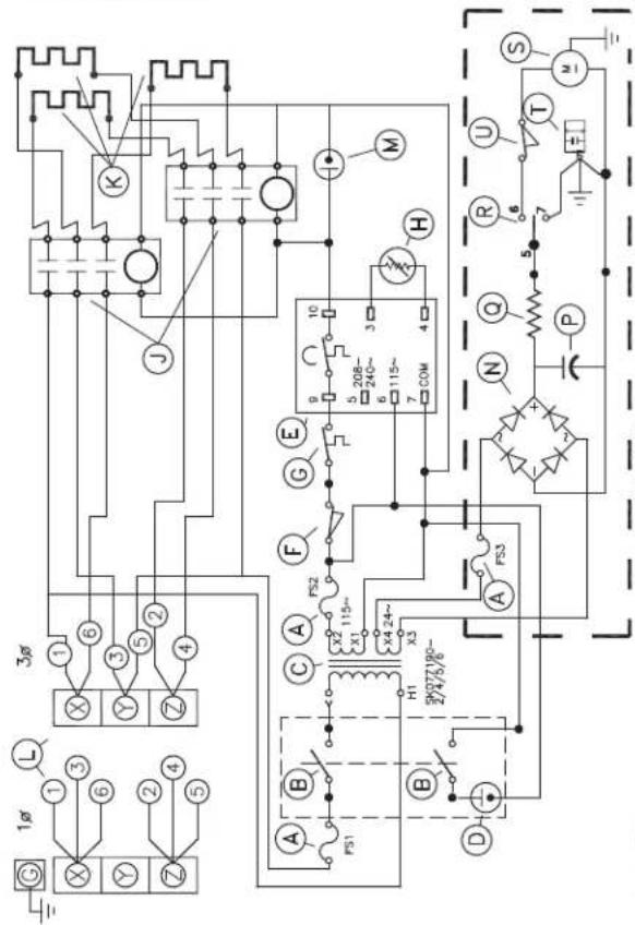
K-ELEMENT L-TERMINAL BLOCK M-PILOT-YELLOW N-RECTIFIER P-CAPACITOR Q-RESISTOR R-TILT CONTROL S-MOTOR T-DUMPING VALVE U-LIMIT SWITCH POWER TILT ONLY
| K-ELEMENT |
| L-BLOC D'ALIMENTATION |
| M-VEILLEUSE-JAUNE |
| N-RECTIFICATEUR |
| P-CONDENSATEUR |
| Q-RÉSISTANCE |
| R-COMMUTATEUR DIRECTIONNEL |
| S-MOTEUR |
| T-DECHARGER SOUPAPE |
| U-COMMUTATEUR DE LIMITE |
| INCLINER D'ALIMENTATION SEULEMENT |
| CAUTION: REPLACE WITH SAME TYPE FUSES ATTENTION: REPLACER PAR UN FUSIBLE DU MÈME TYPE | |
| MODELS/MODELES POWER TILT/BASCULANT AUTO FS3 15A MDA FS2 1A AGC FS1 1.5A MDL 110-240V MODELS ONLY MODELES SEULEMENT | MODELS/MODFLFS HAND TILT/BASCULANT MANUEL FS3 NOT USED/INUTILISE FS2 1A AGC FS1 .5A AGC 110-240V MODELS ONLY MODELES SEULEMENT |
SK90123-2H
208/240/380/415/480V F30,40E-L,MR/SEL,M-30,40-TR
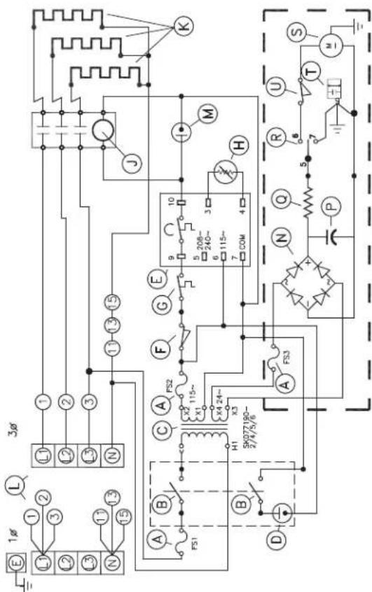
K-ELEMENT L-TERMINAL BLOCK M-PILOT-YELLOW N-RECTIFIER P-CAPACITOR Q-RESISTOR R-TILT CONTROL S-MOTOR T-DUMPING VALVE U-LIMIT SWITCH POWER TILT ONLY
| K-ELEMENT |
| L-BLOC D'ALIMENTATION |
| M-VEILLEUSE-JAUNE |
| N-RECTIFICATEUR |
| P-CONDENSATEUR |
| Q-RÉSISTANCE |
| R-COMMUTATEUR DIRECTIONNEL |
| S-MOTEUR |
| T-DECHARGER SOUPAPE |
| U-COMMUTATEUR DE LIMITE |
| - - INCLINER D'ALIMENTATION SEULEMENT |
A-FUSIBLE B-COMMUTATEUR DE POUVOIR C-TRANSFORMATEUR D-VEILLEUSE-ROUGE E-THERMOSTAT ÉLECTRONIQUE F-INTERRUPTEUR DE POUVOIR G-COMMUTATEUR DE SECURITE H-CAPTEUR DE RTD J-CONTACTEUR
| CAUTION: REPLACE WITH SAME TYPE FUSESATTENTION: REPLACER PAR UN FUSIBLE DU MÊME TYPE | |
| MODELS/MODELESPOWER TILT/BASCULANT AUTOFS315A MDAFS21A AGCFS11.5A MDL 110-240VMODELS ONLYMODELES SEULEMENT | MODELS/MODELESHAND TILT/BASCULANT MANUELFS3NOT USED/INUTILSFS21A AGCFS1.5A AGC 110-240VMODELS ONLYMODELES SEULEMENT |
SK90123-1H
220/380,240/415V 3N\~ F30,40E-L,MR/SEL,M-30,40-TR
Every new piece of Welbilt Foodservice equipment comes with KitchenCare® and you choose the level of service that meets your operational needs from one restaurant to multiple locations
StarCare – Warranty & lifetime service, certified OEM parts, global parts inventory, performance audited
ExtraCare — CareCode, 24/7 Support, online/mobile product information
LifeCare – Install & equipment orientation, planned maintenance, KitchenConnect™, MenuConnect®
Talk with KitchenCare® • 1-844-724-CARE • www.mtwkitchencare.com

WELBILT
KitchenCare
To learn how Welbilt Foodservice and its leading brands can equip you, visit our global web site at www.welbilt.com, then discover the regional or local resources available to you.
- TR Electric Braising Pan
- Installation, Operation, Maintenance, Parts & Service
- Models:
- TABLE OF CONTENTS
- POUR VOTRE SÉCURITÉ
- RECEIVING INSPECTION
- SHIPPING DAMAGE INSTRUCTIONS
- UNCRATING
- ! CAUTION:
- VENTILATION
- POSITIONING
- Caution:
- ELECTRICAL
- ENSURE THE ELECTRICAL SUPPLY MATCHES THE UNIT'S REQUIREMENTS AS STATED ON THE ELECTRICAL RATING LABEL.
- General Information
- Connection
- WATER (OPTIONAL)
- INSTALLATION CHECKS
- CLEANING
- OPERATING INSTRUCTIONS
- # DESCRIPTION
- POWER TILT MANUAL OVERRIDE INSTRUCTIONS
- WARNING / AVERTISSEMENT / ADVERTENCIA
- OPERATING THE UNIT
- OPERATING SUGGESTIONS
- CLEANING INSTRUCTIONS
- CARE AND CLEANING
- WARNINGS
- NOTES
- DISPOSAL INSTRUCTIONS
- PREVENTATIVE MAINTENANCE
- DAILY PRE-STARTUP INSPECTION
- WARNING:
- SIX MONTH SERVICE INSPECTION
- YEARLY SERVICE INSPECTION
- TROUBLESHOOTING AND MAINTENANCE PROCEDURES
- CALIBRATION INSTRUCTIONS
- RECOMMENDED SPARE PARTS LIST
- SERVICE PARTS
- WARRANTY
- ITEM # PART # DESCRIPTION QTY.
- MANUAL TILT ASSEMBLY
- HYDRAULIC JACK ASSEMBLY
- OIL TANK ASSEMBLY
- ITEM NO. PART NO. DESCRIPTION QTY.
- SHAFT ASSEMBLY
- PAN HINGE
- FRAME / LID ASSMEBLY
- ELECTRICAL BOX
- POWER TILT
Brand : Cleveland
Model : SEL-40-TR
Category : Saucepan