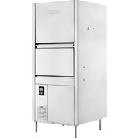
PW10N-BAS - Dishwasher Hobart - Free user manual and instructions
Find the device manual for free PW10N-BAS Hobart in PDF.


| Product type | Professional hood-type dishwasher (wash battery) |
| Model | PW10N-BAS |
| Brand | Hobart |
| Wash tank capacity | 21 gallons (79.5 liters) |
| Rinse water consumption per cycle | 1.2 gallons (4.5 liters) |
| Electrical supply | 208/240 V, 60 Hz, 3-phase, 49/54.5 A |
| Tank heater power | 16.4 kW |
| Rinse booster power | 16.4 kW |
| Wash pump motor | 4 HP |
| Wash cycles | 2, 4, or 6 minutes (followed by a 10-second rinse) |
| Disinfection mode | Hot water only (wash ≥ 65.6°C, rinse ≥ 82.2°C) |
| Water supply required | Hot water only (43°C – 60°C recommended) |
| Water pressure required | 15 – 65 PSIG (1.03 – 4.48 bar) |
| Electrical connection | Single point, via front terminal block |
| Water connection | 2.74 m fill hose with 3/4" female fitting |
| Drain connection | 1.6 cm inner diameter hose, 2.4 m long |
| Material | Stainless steel |
| Dimensions (W x D x H) | Not specified in the manual (see technical data sheet) |
| Weight | Not specified in the manual |
| Maintenance | Daily cleaning of filters, wash arms, and regular descaling |
| Programming | Management menu with PIN code (default 1001) |
| Connectivity | Built-in WiFi (Hobart SmartConnect app) |
| Warranty | See Hobart website for terms |
Frequently Asked Questions - PW10N-BAS Hobart
User questions about PW10N-BAS Hobart
0 question about this device. Answer the ones you know or ask your own.
Ask a new question about this device
Download the instructions for your Dishwasher in PDF format for free! Find your manual PW10N-BAS - Hobart and take your electronic device back in hand. On this page are published all the documents necessary for the use of your device. PW10N-BAS by Hobart.
USER MANUAL PW10N-BAS Hobart
IN MO IN D E U C T D, E M O N C I O L P O N E S
PW10n/PW20n/PW12n PREP WASHER

MODELS
PW10n-BAS
PW10n-ADV
PW10n-ADVSW
PW20n-BAS
PW20n-ADV
PW12n-ADV
PW12n-ADVSW
natural_image
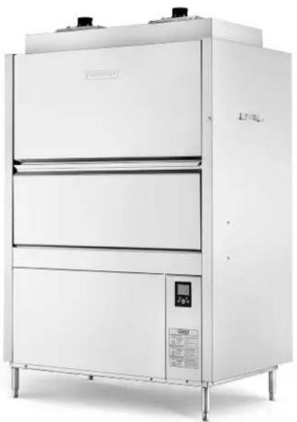
Exterior view of a stainless steel industrial oven with control panel and side-mounted unit (no visible text or symbols)HOBART
701 S. RIDGE AVENUE
TROY, OHIO 45374-0001
937 332-3000
www.hobartcorp.com
F-41318 (March 2025)
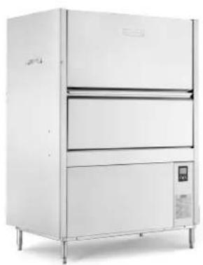
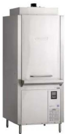
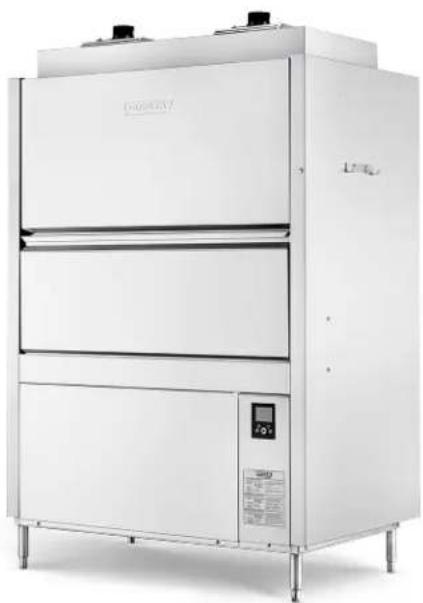
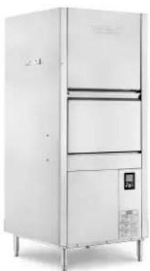
Model PW10n-BAS Model PW10n-ADV / PW10n-ADVSW
natural_image
Exterior view of a modern stainless steel industrial refrigerator with control panel and display (no visible text or symbols)
natural_image
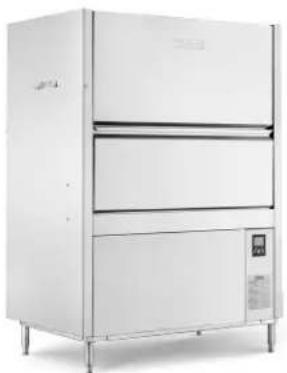
Exterior view of a modern stainless steel industrial machine (no visible text or symbols)Model PW20n-BAS
natural_image
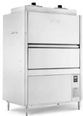
Exterior view of a modern stainless steel industrial machine (no visible text or symbols)Model PW20n-ADV

natural_image
Exterior view of a three-tiered stainless steel industrial oven (no visible text or labels)Model PW12n-ADV / PW12n-ADVSW
natural_image
Exterior view of a modern stainless steel laboratory oven with control panel and digital display (no visible text or symbols)TABLE OF CONTENTS
GENERAL....4
INSTALLATION....5
Unpacking....5
Unpacking From Pallet 5
Removing Energy Recovery Assembly (If Necessary) 5
Installation Codes 9
Location 9
Plumbing Connection(s) 9
Water Requirements 9
Water Supply Connection 10
Drain 11
Venting Requirements. 12
Canopy Size and Location 12
Rate of Exhaust Flow Calculations 12
Vent Exit (Models PW10n-BAS / PW20n-BAS).... 13
Vent Fan Control (Standard); Power Vent Fan (Optional) (Models PW10n-BAS / PW20n-BAS) . . 13
Electrical Connection(s) 14
Connection Method 14
Rotation of Pump Motor(s) 15
Equipment Connections 16
Vent Fan Control 16
Chemical Feeder Installations....17
Detergent Feeder (By Others)....17
Rinse Aid Feeder (By Others) 18
Delime Feeder (PW10n-ADV / PW10n-ADVSW / PW20n-ADV / PW12n-ADV / PW12nADVSW) .. 18
PW10n-ADVSW / PW12n-ADVSW External Chemical Dispenser Connection for
Chemical Lockout 18
OPERATION....19
Preparation 19
Ware Washing....21
CLEANING 22
Delime Instructions 23
Manual Delime Process (Models PW10n-BAS and PW20n-BAS) 23
Auto Delime Process (PW10n-ADV, PW10n-ADVSW, PW20n-ADV, PW12n-ADV and
PW12n-ADVSW) 23
Do's and Don'ts for your New Hobart Dishwasher 24
PROGRAMMING 25
Manager Menu 25
Manager Menu Parameters 25
Hobart SmartConnect App 28
Getting Connected 28
MAINTENANCE 30
Wash Arms 30
Motor(s)....30
Delime Chemical Pump (PW10n-ADV, PW10n-ADVSW, PW20n-ADV, PW12n-ADV and
PW12n-ADVSW Models Only) 30
Cleaning Baffles On PW10n-ADV, PW10n-ADVSW, PW20n-ADV, PW12n-ADV and
PW12n-ADVSW Models 30
TROUBLESHOOTING 32
Error Code Chart with Possible Solutions....32
SERVICE 36
PWn Expendable Parts....36
Installation, Operation and Care Of Model PW10n / PW20n / PW12n Prep Washer SAVE THESE INSTRUCTIONS
GENERAL
The PWn Prep Washers occupy a minimum amount of floor space and do not require separate dish tables. For all PW10n and PW20n models, the upper portion of the door raises, while the lower portion swings out to provide a drain platform. The rack can then be pulled out for easy loading and unloading. The PW12n models feature a single piece vertical lift door. The unit can accommodate a 140-quart Hobart mixer bowl.
All PWN models are designed to operate in hot water sanitizing mode only; designated by the NSF temperature requirements of 150^ F wash and 180^ F final rinse. These temperatures can be found on the data label located under the controls on the lower part of the machine.
The HMI controls allow the operator to select a 2-, 4- or 6-minute cycle. The wash cycle is followed by a dwell cycle and then a 10 second rinse. The PW10n-ADV, PW10n-ADVSW, PW12n-ADV and PW12n-ADVSW Advansys models include a 70 second condensing cycle following the rinse cycle and the PW20n-ADV Advansys model includes a 90 second condensing cycle. The upper and lower wash arms provide thorough cleaning, and the upper and lower rinse arms provide a sanitizing rinse at the end of each cycle. The PW10n-ADVSW and PW12n-ADVSW models also include a side wash system.
All PWn models are only available with 16.4 kW electric tank heat and the built-in 16.4 kW electric booster heater is standard on all models. The booster heater is designed to maintain a minimum final rinse temperature of 180^ F provided the incoming water temperature is 110^ F minimum. For ventless models PW10n-ADV, PW10n-ADVSW, PW20n-ADV, PW12n-ADV and PW12n-ADVSW, the booster heater is designed to maintain a minimum final rinse temperature of 180^ F with cold incoming water of at least 55^ F.
The wash pump motor on the PW10n and PW12n models is rated at 4 HP. The PW20n models utilize two wash pump motors for a total of 8 HP.
The fill line incorporates an air gap on all models to prevent any back flow of water from the prep washer into the potable water supply. The unit, once turned on, fills the wash tank to the appropriate level and automatically stops filling once the proper level is reached. A pressure sensor reads the water level in the wash tank and shuts the heat off if the water level becomes too low. When the water returns to the proper level, the heating circuit resumes operation.
The PW10n-BAS and PW20n-BAS models require a single hot water supply while the PW10n-ADV, PW10n-ADVSW, PW20n-ADV, PW12n-ADV and PW12n-ADVSW models require a hot water supply and a cold-water supply.
An automatic pumped drain and pumped rinse system are standard on all models.
Ventless models PW10n-ADV, PW10n-ADVSW, PW20n-ADV, PW12n-ADV and PW12n-ADVSW do not require a vent hood. These models are equipped with an internal condensing system to minimize the water vapor escaping from the unit. The PW10n-BAS and PW20n-BAS models typically require a vent hood over the unit to meet local codes. Refer to pages 12-13 for venting and hood requirements.
The serial number can be found on the machine data plate located at the bottom right corner of the upper door on PW10n and PW20n models and on the front right side of the machine above the controls on PW12n models.
INSTALLATION
UNPACKING
Immediately after unpacking the PWn Prep Washer, check for possible shipping damage. If the machine is found to be damaged, save the packaging material and contact the carrier within 5 business days after delivery.
Prior to installation, test the electrical service to ensure that it agrees with the specifications on the data plate located on the bottom right of the upper door (PW10n and PW20n models) or above the controls on the front right side of the machine (PW12n models).
Unpacking From Pallet
Carefully unpack the machine from the pallet.
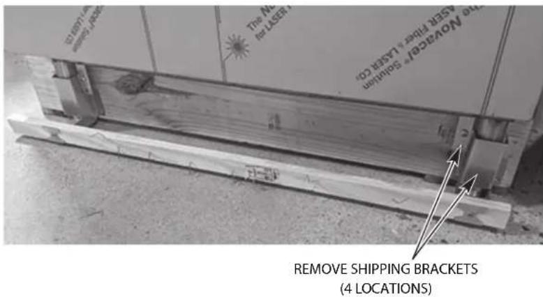
- Remove the shipping brackets from the machine/pallet (4 locations) and discard the two pallet extension boards and brackets.
text_image
STANDARD SHIPPING BRACKETS THE NAME OF LEAVATORY SLINER THE ANOVALES SLINER REMOVE SHIPPING BRACKETS (4 LOCATIONS)Fig. 1
-
Lower the adjustable feet by rotating clockwise until the machine raises off the skid.
-
With the machine resting on the feet, slide the pallet out from underneath the machine.
Removing Energy Recovery Assembly (If Necessary)
WARNING Disconnect the electrical power to the machine and follow lockout / tagout procedures. There may be multiple circuits. Be sure all circuits are disconnected.
If the PWn is too tall to pass through a door opening, follow the procedure below to remove the energy recovery assembly(s).
NOTE: One energy recovery assembly is shown in the following steps. If removing both assemblies from the PW20n-ADV models, repeat steps 2 though 9 for each assembly.
-
For PW10n-ADV, PW10n-ADVSW, PW12n-ADV and PW12n-ADVSW models, remove the right-side panel. For PW20n-ADV models, remove the left-side panel.
-
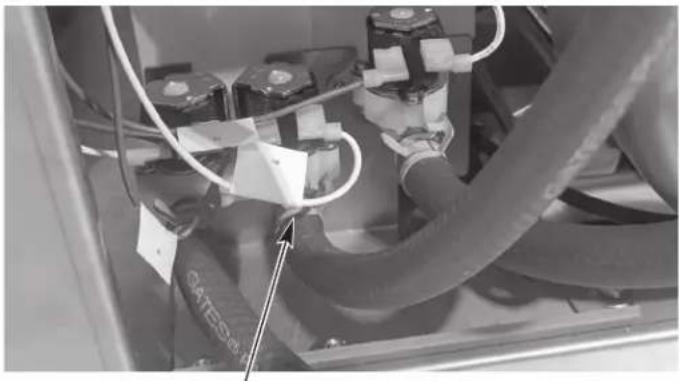
Disconnect the red fill hose from the fill solenoid valve and allow the water to drain. Reinstall the hose after all the water has drained.
natural_image
Close-up of industrial electrical equipment with hoses and components (no visible text or symbols)DISCONNECT FILL HOSE TO DRAIN WATER FROM COIL
Fig. 2
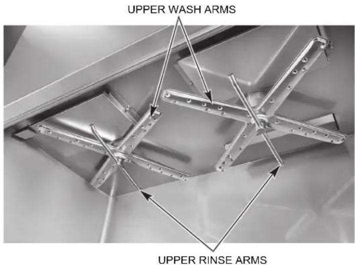
- Remove the upper wash and rinse arms.
text_image
UPPER WASH ARMS UPPER RINSE ARMSFig. 3
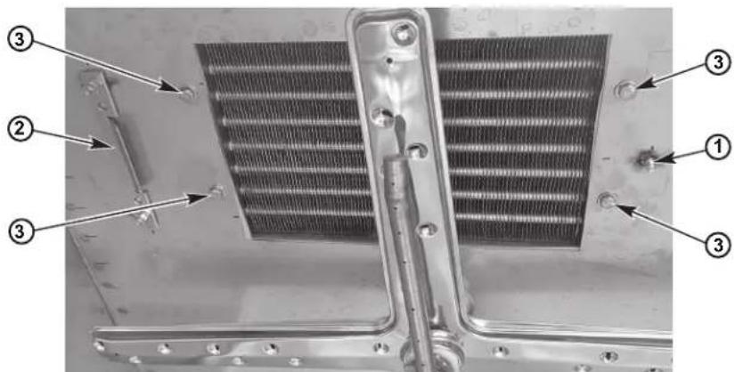
- Remove the baffle (located under the wash and rinse arms at the top of the chamber).
a. Remove the nut and washer from the stud located on the opposite side of the baffle from the holding bracket (1, Fig. 4).
b. Slide the baffle to the side to free the baffle from the holding bracket (2, Fig. 4).
c. Remove the (4) bolts, lock washers and washers (3, Fig. 4) that secure the energy recovery assembly from inside the wash chamber.
NOTE: When reinstalling the bolts, ensure there is sufficient permagum on the bolt threads. Reapply permagum as required.
text_image
Labeled diagram of a heat exchanger or radiator panel with numbered components and directional arrows indicating parts of the component.Fig. 4
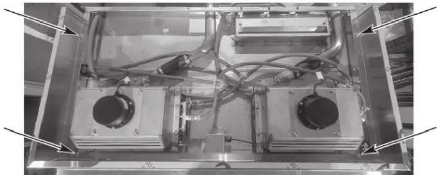
- Remove the shroud on top of the unit by removing the (4) bolts.
natural_image
Interior view of an electronic device with two central modules and wiring, no visible text or symbolsFig. 5
- Disconnect the blower motor cable connector.
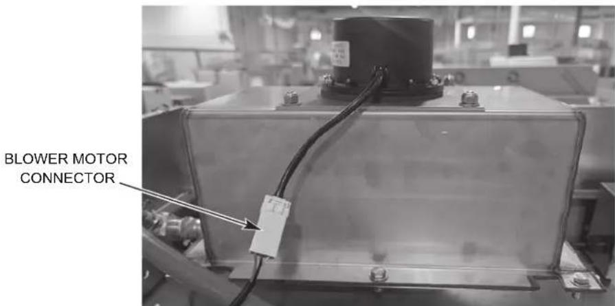
text_image
BLOWER MOTOR CONNECTORFig. 6
- Disconnect the (2) water hoses connected to the energy recovery assembly.
NOTE: Ensure the hoses are connected to the proper connection points when reinstalling. The hose from the solenoid valve connects to the top connection and the hose from the air gap connects to the bottom connection.
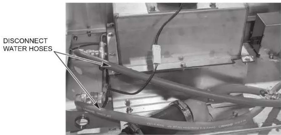
text_image
DISCONNECT WATER HOSESFig. 7
- Remove the (4) nuts securing the energy recovery assembly to the top of the chamber and lift the energy recovery assembly off the machine.
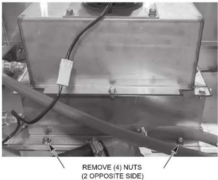
text_image
REMOVE (4) NUTS (2 OPPOSITE SIDE)Fig. 8
- Once the unit is in the dish room area, reverse the above procedure to reinstall the energy recovery assembly.
NOTE: When reinstalling the energy recovery assembly(s), ensure the gasket(s) is properly installed providing a proper seal.
INSTALLATION CODES
Installation must be in accordance with state and local codes, and the National Electrical Code ANSI/NFPA70 (latest edition). In Canada, the installation code is CSA 22.1 (latest edition).
LOCATION
Before finalizing the location, ensure consideration has been given for the electrical conduit, water supply, drain connection, venting (if applicable), chemical feeder replenishment (if applicable) and adequate clearance for opening the door.
The prep washer must be level before any connections are made. Turn the threaded feet (Fig. 9) as required to level the machine.
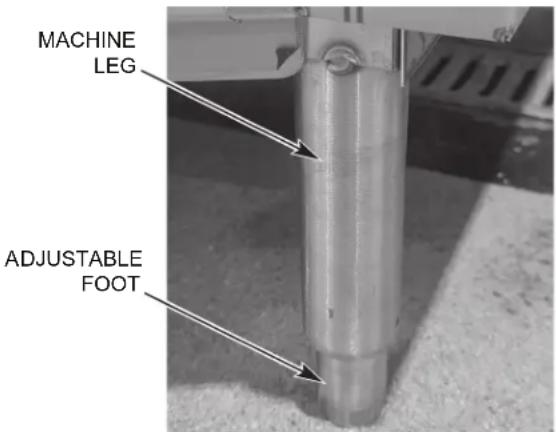
text_image
MACHINE LEG ADJUSTABLE FOOTFig. 9
Allow a minimum of 3" clearance at the rear of the machine and 18" at the sides of the machine for service access.
PLUMBING CONNECTION(S)
⚠ WARNING Plumbing connections must comply with applicable sanitary, safety, and plumbing codes.
Water Requirements
Proper water quality can improve ware washing performance by reducing spotting, enhancing effectiveness of labor and extending equipment life. Water conditions vary from one location to another. The recommended proper water treatment for effective and efficient use of this equipment will also vary depending on the local water conditions. Ask your municipal water supplier for details about your local water conditions prior to installation.
Recommended water hardness is 3 grains of hardness per gallon or less. Higher hardness may cause excessive formation of lime scale. Water hardness above 3 grains per gallon requires water treatment. Water treatment has been shown to reduce costs associated with machine cleaning, reduce deliming of the dishwasher, and reduce detergent usage in the dishwasher. Chlorides must not exceed 50 ppm.
NOTICE High iron levels in the water supply can cause staining and may require an iron filter. High chloride levels in the water supply can cause pitting and may require a chloride removal system. Contact your local water treatment professional for proper water treatment.
Sediment may require a particulate filter. Dissolved solids may require water treatment such as a water softener, reverse osmosis system, etc. Contact your local water treatment professional for proper water treatment.
If an inspection of the dishwasher or booster heater reveals lime build-up after the equipment has been in service, water treatment is recommended. If a water softener is already in place, ensure there is a sufficient level of salt. Contact your local Hobart Service office for specific recommendations.
Water Supply Connection
The plumber connecting this machine is responsible for making certain that water lines are THOROUGHLY FLUSHED OUT BEFORE connecting to the dishwasher. This "flush-out" is necessary to remove all foreign matter, such as chips (resulting from cutting or threading of pipes), pipe joint compound from the lines; or, if soldered fittings are used, bits of solder or cuttings from the tubing. Debris, if not removed, may lodge in the dishwasher's plumbing components and render them inoperative. Manual valves or solenoid valves fouled by foreign matter and any expenses resulting from this are NOT the responsibility of the manufacturer and associated repair costs are not covered under warranty.
Water supply requirements are as follows:
WATER SUPPLY REQUIREMENTS
| Model | Sanitizing Mode | Connection | Water Supply Temperature | ||
| Minimum M | Maximum Recommended | ||||
| PW10n-BAS | Hot Water Sanitizing | Hot Water 1 | 10^ ( 43^ ) N/A | 140^ ( 60^ ) | |
| PW20n-BAS | |||||
| PW10n-ADV | Hot Water Sanitizing | Hot Water 1 | 10^ ( 43^ ) N/A | 140^ ( 60^ ) | |
| PW10n-ADVSW | |||||
| PW20n-ADV | |||||
| PW12n-ADV | Cold Water 5 | 5^ ( 13^ ) 90^ | F ( 32^ ) 65^ | ( 18^ ) | |
| PW12n-ADVSW | |||||
PW10n-ADV, PW10n-ADVSW, PW20n-ADV, PW12-ADV and PW12n-ADVSW models require both a cold water supply connection and a hot water supply connection.
NOTICE On PW10n-ADV, PW10n-ADVSW, PW20n-ADV, PW12n-ADV and PW12n-ADVSW installations, the cold water supply must not exceed 90°F (32°C) for proper operation. Optimal results are obtained when cold water supply temperature is below 65°F (18°C). For best results, it may be necessary to use 12 " pipe for cold water pipe size and minimize the distance between the dishwasher and the entrance into the building. Pipe insulation will also improve results.
If cold water supply temperature is consistently above 90^ F ( 32^ C) or if excessive water vapor or steam is entering the room after the condensing cycle is complete, contact Hobart Service to increase condensing time.
Required flowing water pressure to the dishmachine is 15-65 PSIG. If flowing pressures higher than 65 PSIG are present, a pressure regulating valve must be installed in the water line to the dishmachine (by others). If flowing pressure is less than 15 psi, improper machine operation may result. All PWn models are equipped with a pumped rinse system; therefore, a water pressure gauge is not required and is not supplied with the machine.
NOTICE The water pressure regulator must have a relief bypass. Failure to use the proper type of pressure regulator may result in damage to the unit.
A manual shutoff valve (not supplied) should be installed upstream of the fil accommodate servicing the machine. It is recommended that a line strainer (not supplied) be installed in the supply line between the manual shutoff valve (not supplied) and the connection point on the machine. Make plumbing connections with 12 " minimum copper piping OD ( 34 " recommended) with a 34 " male garden hose fitting (not supplied).
The PW10n-BAS and PW20n-BAS models ship with a 9' long fill hose with a 34 " female garden hose fitting for the hot water supply. The PW10n-ADV, PW10n-ADVSW, PW20n-ADV, PW12n-ADV and PW12n-ADVSW models ship with two 9' long fill hoses with 34 " female garden hose fittings; one for the hot water supply and one for the cold-water supply. The fill hoses are factory installed at the water valves located at the base of the machine towards the back. For the PW10n and PW12n models, remove the right-side panel and route the hot and cold water (if equipped) fill hoses through the hole at the base of the machine in the back for installation to the facility connection(s). For the PW20n models, remove the left side panel and route the hot and cold water (if equipped) fill hoses through the hole at the base of the machine in the back for installation to the facility water connection(s).
NOTE: The fill hoses have an identification tag for hot and cold water located at the female garden hose connection. For the -ADV and -ADVSW models, ensure the hot and cold-water hoses are connected to the proper water supply connections.
Drain
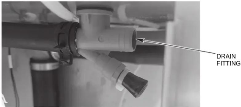
A drain hose, 58 " inside diameter and 8' long, is provided shipped loose inside the machine. Connect one end of the hose to the barbed fitting located under the machine (Fig. 10).
NOTE: The barbed fitting is located behind the right side panel under the tank. The other end of the drain hose should be securely plumbed into a drain. Use care not to kink hose. The drain must have a minimum flow capacity of 21 gallons per minute. The drain hose height cannot exceed 40" above the finished floor.
text_image
DRAIN FITTINGFig. 10
VENTING REQUIREMENTS
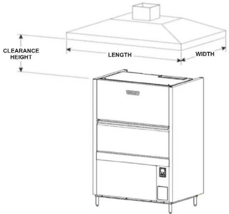
For PW10n-BAS and PW20n-BAS models, Type II canopy hoods are required. Hoods must be installed according to the manufacturer's instructions. Make-up air must be provided so that the exhaust flow rate results in a negative building pressure in the room where the unit is located (more exhaust air than outside air). Factory-built hoods not tested to UL standard 710 and custom-built hoods must comply with the following specifications: stainless steel should have a minimum thickness of 0.037 in. (0.94 mm) [No. 20 Gauge] or copper sheet weighing at least 24 ounces per square foot (7 Kg/m2); the hood must be secured in place by noncombustible supports and must meet the RATE of EXHAUST FLOW CALCULATIONS.
NOTICE Ensure the installation meets local codes.
text_image
CLEARANCE HEIGHT LENGTH WIDTHFig. 11
Canopy Size and Location
The inside lower edge of canopy-type Type II commercial hoods shall overhang or extend a horizontal distance of not less than 6 inches (152 mm) beyond the edge of the top horizontal surface of the appliance on all open sides. The vertical distance between the front lower lip of the hood and such surface shall not exceed 4 feet (1219 mm) with a minimum of 1 foot (305 mm).
18" minimum overhang of the front opening.
Rate of Exhaust Flow Calculations
Based on the 2021 International Mechanical Code.
The minimum net airflow for Type II hoods used for dishwashing appliances shall be 100 cfm per linear foot of hood length. The net quantity of exhaust air shall be calculated by subtracting any airflow supplied directly to a hood cavity form the total exhaust flow rate of a hood.
Models PW10n-ADV, PW10n-ADVSW, PW20n-ADV, PW12n-ADV and PW12n-ADVSW do not require a Type II vent hood. According to 507.3 of the 2021 IMC, Type II hoods are not required where the heat and moisture loads are incorporated into the HVAC system design. Refer to the below table for heat dissipation or heat gain to space machine data.
PWn HEAT DISSIPATION
| Model | Latent Heat (BTU/HR) | Sensible Heat (BTU/HR) |
| PW10n-BAS 12,300 5,300 | ||
| PW10n-ADV, PW10n-ADVSW PW12n-ADV, PW12n-ADVSW | 9,900 6,300 | |
| PW20n-BAS 14,900 6,400 | ||
| PW20n-ADV 14,200 8,700 |
Vent Exit (Models PW10n-BAS / PW20n-BAS)
A vent exit (4-9/16 " x 17-3/8") is provided at the top of the machine to allow for expansion of air. DO NOT directly connect the vent to an external vent.
Vent Fan Control (Standard); Power Vent Fan (Optional) (PW10n-BAS / PW20n-BAS)
The vent fan control feature is standard on all PW10n-BAS and PW20n-BAS models. This feature is not available on the ventless models. The vent fan control relay provides switch contacts only and does not provide power to the facility's exhaust fan motor. The rating for the vent fan control relay connected to terminals VFC1 and VFC2 is 1.5 amps at nameplate supply voltage. When the machine is connected to the vent fan control circuit, the facility's exhaust fan is switched on when the machine is powered on and off when the machine is powered off.
The Power Vent Fan accessory exhausts moist air from the chamber after the rinse cycle is completed. The power vent fan may be selected to operate for 40, 60 or 80 seconds. The power vent fan kit (field installed only) extends upward 12-1/4" above the vent exit (13-5/16" above the top of the wash chamber) and terminates in a round duct connection for a 10-1/4" O.D. duct.
Install power vent fan kit using a maximum of 60 ft of 10" diameter straight duct; or, 50 ft of straight and two (2) 90°elbows, or equivalent. Distances greater than the stated maximum lengths may reduce venting efficiency.
NOTE: Refer to the Prep Washer Power Vent Fan Kit Installation Instructions (F-46049) for more detailed information.

⚠ WARNING Electrical and grounding connections must comply with applicable portions of the National Electrical Code (NFPA No. 70, latest edition) and/or other local electrical codes.
⚠ WARNING Disconnect the electrical power to the machine and follow lockout / tagout procedures. There may be multiple circuits. Be sure all circuits are disconnected.
Connect the incoming power to the machine in accordance with the wiring diagram located on the back of the front trim panel.
ELECTRICAL DATA
| Model Volts | Hertz Phase | Rated Amps | Minimum Supply Circuit Ampacity | Maximum Protective Device (Amps) | |
| Single Point Electrical Connection | |||||
| PW10n-BAS | 208 / 240 | 60 3 49 | 2 / 54.5 | 60 / 70 60 / 70 | |
| PW10n-ADV | 480 60 | 3 29.7 | 3 5 35 | ||
| PW10n-ADVSW | |||||
| PW12n-ADV | |||||
| PW12n-ADVSW | |||||
| PW20n-BAS | 208 / 240 | 60 3 60 | 2 / 65.5 | 70 / 80 70 / 80 | |
| PW20n-ADV | 480 60 | 3 36.7 | 4 5 45 | ||
* Minimum Supply Circuit Ampacity / Maximum Protective Device (Amps) compiled in accordance with the National Electrical Code (NFPA 70), latest edition.
* * For supply connection, use wires suitable for at least 90°C or equivalent.
Connection Method
- Remove the lower front panel and open the controls door by removing the three screws at the bottom.
- A conduit hole is supplied at the back of the machine at the base of the unit. If necessary due to space requirements, use a 45^ fitting. NOTE: Facing the front of the machine, the conduit hole is located on the right side at the base on PW10n and PW12n models. For PW20n models, the conduit hole is located on the left side at the base of the machine.
- Install conduit and fitting. Feed wires thru base of unit to front of unit. Keep excess wire in the base of the unit to a minimum.
- Make electrical connection according to the machine data plate and the wiring diagram supplied with the machine and secure wires to the 1TB terminal block located at the front of the machine (Fig. 12).

natural_image
Close-up of an electrical control panel with wiring and components (no visible text or symbols)1TB TERMINAL BLOCK
PW20n shown. For PW10n & PW12n models, 1TB is located in the front right corner of the controls.
Fig. 12
- Close the controls door and reinstall the lower front panel and secure with the three screws removed in step 1.
Rotation of Pump Motor(s)
Before using the machine, check the pump motor rotation to be sure it is rotating in the right direction.
PW10n-BAS / PW10n-ADV / PW10n-ADVSW / PW12n-ADV / PW12n-ADVSW
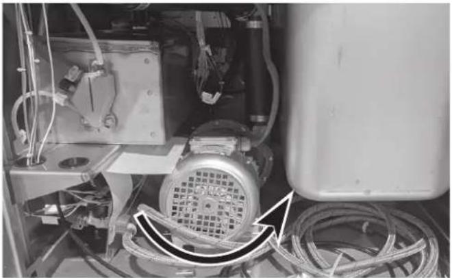
From the front of the machine, the motor should rotate clockwise. Looking from the rear of the machine, the correct rotation is counterclockwise. Inspection is easiest from the rear of the machine using a flashlight and mirror to check the motor fan rotation. Be aware that the mirror will reverse the perceived direction.
natural_image
Close-up of an industrial electrical equipment with coiled cables and a motor (no visible text or symbols)PW10n-BAS / PW10n-ADV / PW10n-ADVSW / PW12n-ADV / PW12n-ADVSW (REAR VIEW)
Fig. 13
PW20n-BAS / PW20n-ADV
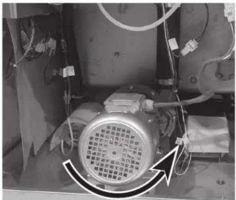
Pump motor 1 – Looking from the right side of the machine, the correct rotation is counterclockwise. Inspection is easiest from the right side using a flashlight to check the motor fan on the rear of the motor.
Pump motor 2 – Looking from the left side of the machine, the correct rotation is counterclockwise. Inspection is easiest from the left side using a flashlight to check the motor fan on the rear of the motor.
natural_image
Close-up of a mechanical component with visible wiring and a circular component, no text or symbols present.PW20n-BAS / PW20n-ADV (LEFT VIEW)
Fig. 14
If the pump motor(s) is/are rotating in the wrong direction, follow this procedure.
WARNING the electrical power to the machine and follow lockout / tagout procedures. There may be multiple circuits. Be sure all circuits are disconnected.
Reverse any two of the three incoming line wires (not the ground wire). Reconnect and recheck rotation of pump motor.
EQUIPMENT CONNECTIONS
⚠ WARNING Electrical and grounding connections must comply with applicable portions of the National Electrical Code (NFPA No. 70, latest edition) and/or other local electrical codes.
⚠ WARNING Disconnect the electrical power to the machine and follow lockout / tagout procedures. There may be multiple circuits. Be sure all circuits are disconnected.
Vent Fan Control
The vent fan control feature is standard on all non-ventless PWN models. The vent fan control relay provides switch contacts only and does not provide power to the vent fan motor. The rating for the vent fan control relay connected to terminals VFC1 and VFC2 is 1.5 amps at nameplate supply voltage. When the prepwasher is connected to the vent fan, the vent fan is switched on when the prepwasher is on, and off when the prepwasher is off.
Chemical Feeder Installations
This machine must be operated with an automatic detergent feeder, including a visual means to verify that detergents are delivered or a visual or audible alarm to signal if detergents are not available for delivery to the washing system. Chemical feeders are supplied and installed by others.
The PW10n-BAS, PW10n-ADV and PW12n-ADV models have a 21-gallon wash tank capacity and use 1.2 gallons of rinse water per cycle. The PW10n-ADVSW and PW12n-ADVSW models have a 21-gallon wash tank capacity and use 1.47 gallons of rinse water per cycle. The PW20n-BAS and PW20n-ADV models have a 34-gallon wash tank capacity and use 2.35 gallons of rinse water per cycle. This information is used when setting the detergent and rinse aid pumps for proper chemical concentrations.
All PWn models provide an electrical connection point which supplies line voltage power to an external chemical dispenser (provided and installed by others). The maximum rating for the chemical dispenser connected to CPS1 and CPS2 is 1.0 amps.
Detergent Feeder (By Others)
The maximum rating for a detergent dispenser connected to DPS1 and DPS2 is 1.5 amps at line voltage.
If installing a detergent feeder (by others), remove cap to expose 7/8" diameter hole at rear of machine.
NOTE: PW12n-ADV and PW12n-ADVSW models come equipped with a detergent fitting installed at the factory (Fig. 15).

text_image
DETERGENT FITTINGFig. 15
Rinse Aid Feeder (By Others)
The maximum rating for a rinse aid dispenser connected to RPS1 and RPS2 is 1.5 amps at line voltage.
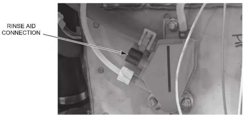
If a rinse agent feeder (by others) is being installed, remove the 14 " compression fitting located on the side of the air trap located on the back side of the booster tank (Fig. 16) to install the rinse aid tube. NOTE: For all PW10n and PW12n models, the booster tank is located on the right side of the machine. For all PW20n models, the booster tank is located on the left side of the machine.
text_image
RINSE AID CONNECTIONFig. 16
Delime Feeder (PW10n-ADV/PW10n-ADVSW/PW20n-ADV/PW12n-ADV/PW12n-ADVSW)
An automatic delime feeder with tubing and standpipe is provided to automatically dispense the delime chemical when needed.
PW10n-ADVSW / PW12n-ADVSW External Chemical Dispenser Connection for Chemical Lockout
All PW10n-ADVSW and PW12n-ADVSW models are provided with an electrical connection point to provide a chemical lockout for an external chemical dispenser. For the lockout signal, the rating of the alarm output from the chemical dispenser must be 24VDC. Connect the (+) alarm output of the chemical dispenser to TB5-ALM+ located in the PWN controls and connect the (-) alarm output of the chemical dispenser to TB5-ALM-.
NOTE: The interconnecting power and signal wires/cable from the external chemical dispenser to the PWn controls are to be provided and installed by others.
OPERATION
PREPARATION
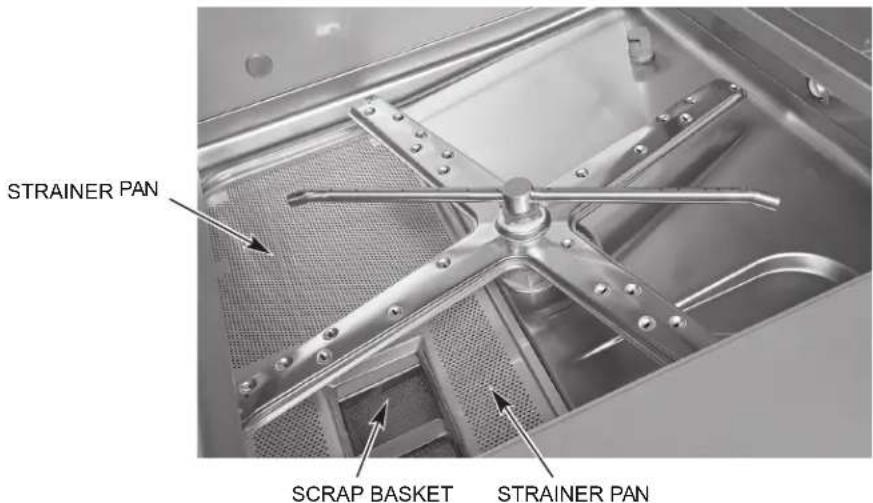
Place the two strainer pans and the scrap basket in their proper positions (Fig. 17).
text_image
STRainer PAN SCRAP BASKET STRainer PANFig. 17
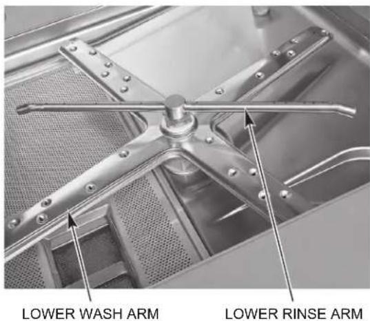
Ensure both upper and lower wash and rinse arms are properly installed and rotate freely (Fig. 18). NOTE: The PW20n models have two sets of upper and lower wash and rinse arms.
text_image
LOWER WASH ARM LOWER RINSE ARM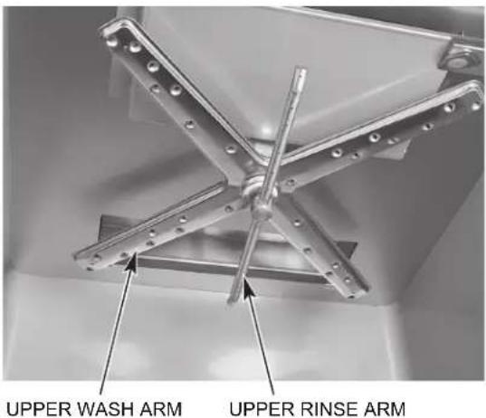
text_image
UPPER WASH ARM UPPER RINSE ARMFig. 18
An automatic detergent dispenser is required. Closely follow the chemical supplier's instructions.
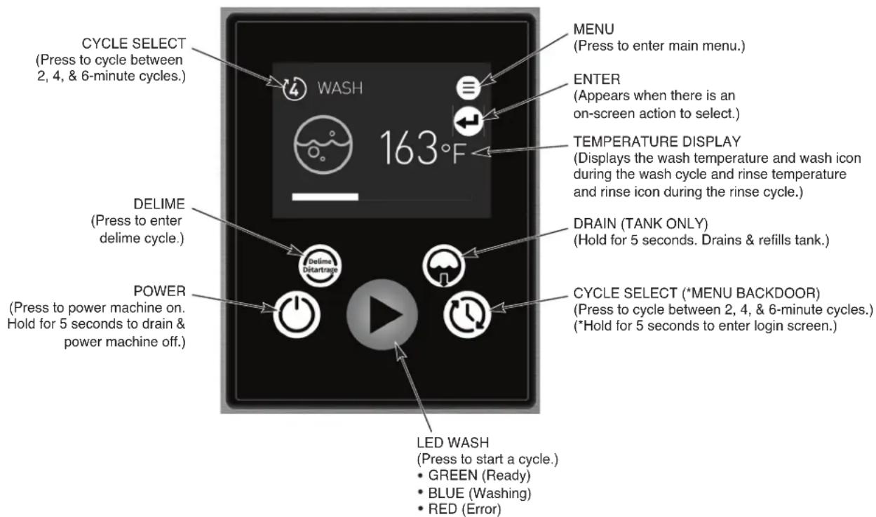
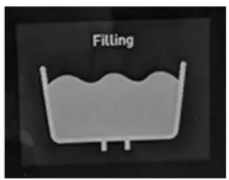
Close the door. Press the POWER button to turn the power on (Fig. 19). If the machine's door is closed and no water is in the tank, the fill cycle will begin automatically. If sufficient water is detected in the tank, the machine will check the temperature of the water and if the water is below 113^ , the machine will drain the water out prior to filling with fresh water. If the water is 113^ or hotter, the machine will proceed to heat the water to the wash tank temperature set point. During the fill cycle, the word FILLING is displayed along with an image of a tank filling to show progress (Fig. 20). Once filled, the unit will display the READY screen along with the wash tank temperature.
text_image
CYCLE SELECT (Press to cycle between 2, 4, & 6-minute cycles.) WASH 163°F MENU (Press to enter main menu.) ENTER (Appears when there is an on-screen action to select.) TEMPERATURE DISPLAY (Displays the wash temperature and wash icon during the wash cycle and rinse temperature and rinse icon during the rinse cycle.) DELIME (Press to enter delime cycle.) DRAIN (TANK ONLY) (Hold for 5 seconds. Drains & refills tank.) POWER (Press to power machine on. Hold for 5 seconds to drain & power machine off.) CYCLE SELECT (*MENU BACKDOOR) (Press to cycle between 2, 4, & 6-minute cycles.) (*Hold for 5 seconds to enter login screen.) LED WASH (Press to start a cycle.) • GREEN (Ready) • BLUE (Washing) • RED (Error)Fig. 19
text_image
FillingFig. 20
NOTE: On machines equipped with the energy recovery feature, it may take up to 20 minutes to complete the fill process.
For ventless models, the door must remain closed until the condensing cycle is complete. All ventless models include a lock to prevent the door from opening until the cycle is complete. A condensing progress bar is displayed during the condensing cycle. Failure to follow these instructions will result in excess steam and water vapor in the dish room.
Scrape the ware to remove large particles of food and debris. Never use steel wool on ware to be loaded into the dishmachine.
Open the door and load the dirty ware into the machine. Do not stack ware one on top of another, as water must have free access to all sides of each piece of ware. Place smaller items and utensils in an open-type rack.
Do not allow foreign objects to enter the unit, especially metallic contaminants.
After loading the machine, close the door. Press the CYCLE SELECT button to choose the appropriate cycle based on the ware type and the amount of food soil on the ware. Refer to the chart below for cycle selection details.
| CYCLE DESCRIPTION | |
| 2 | A 2-minute wash cycle is followed by a 10-second freshwater rinse.(Advansys models have a 70 second (PW10n/PW12n models) or 90 second (PW20n models) condensing cycle following the rinse cycle.) |
| 4 | A 4-minute wash cycle is followed by a 10-second freshwater rinse.(Advansys models have a 70 second (PW10n/PW12n models) or 90 second (PW20n models) condensing cycle following the rinse cycle.) |
| 6 | A 6-minute wash cycle is followed by a 10-second freshwater rinse.(Advansys models have a 70 second (PW10n/PW12n models) or 90 second (PW20n models) condensing cycle following the rinse cycle.) |
| All rinse cycles are followed by a 10-second dwell; except for the PW20n-ADV models which have a 30-second dwell. | |
Throughout the wash cycle, WASH is displayed along with the tank water temperature, the wash icon and a progress bar. During the rinse cycle, RINSE is displayed along with the rinse temperature, the rinse icon and a progress bar. When the rinse cycle is completed, the readout displays the tank water temperature.
On ventless models, CONDENSE is displayed along with a fan icon and a progress bar.
When the display reads CYCLE COMPLETE, open the door and remove the clean ware. The machine is now ready for another cycle.
This machine is not meant to be opened until a cycle has completed, but if an item must be added after the wash cycle has started, open the door slowly, until the pump stops. Wait 10 seconds to allow the wash arms to coast down and to avoid water splashing before opening the door fully.
Operating temperatures for all models are as follows:
| Sanitizing Mode | Minimum Wash Tank Temperature | Minimum Rinse Temperature |
| Hot Water 150°F | (66°C) 180°F (82°C) |
For all -ADV and -ADVSW models only – If excessive amounts of steam or water vapor exit the machine after the cycle is complete and the door is opened, the incoming cold water temperature may be too high. Contact Hobart Service to adjust the condense time. Increasing cycle time will increase water consumption and decrease the racks per hour, but should reduce the steam and water vapor entering the dish room.
CLEANING
The machine must be thoroughly cleaned at the end of each working shift or at least daily. Never use steel wool to clean warewasher surfaces. Use only products formulated to be safe on stainless steel.
-
Press the Power button for 5 seconds (until progress bar is complete). The machine will automatically drain.
-
Once the display has powered off, open the machine door.
-
Thoroughly cleanse and flush the dishwasher interior. Remove remaining soil with a soft cloth or brush and mild cleanser. Rinse again.
-
Remove and empty the scrap basket and strainer. Wash and rinse thoroughly.
-
Clean tank bottom. Do not allow food soil to accumulate on the tank bottom or to enter the drain.
-
Remove standpipe. Wash and rinse standpipe inside and out.
-
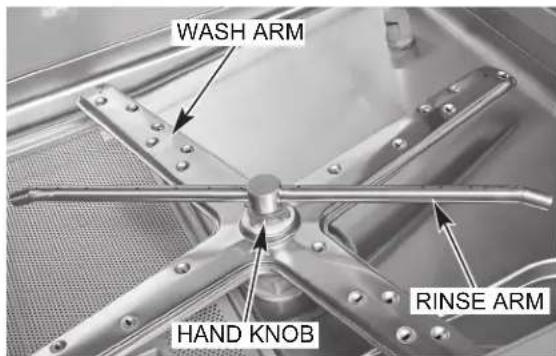
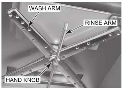
Ensure upper and lower wash and rinse arms (Figs. 21, 22) rotate freely and are free of any obstructions. If not, remove arms and clear out any obstructions. Refer to Maintenance, page 30. NOTE: All PW20n models have two sets of upper and lower wash and rinse arms.
text_image
WASH ARM HAND KNOB RINSE ARMFig. 21
text_image
WASH ARM RINSE ARM HAND KNOBFig. 22
NOTICE Do not bang wash arms or rinse arms to clean.
-
Press and hold manual drain button (page 20, Fig. 19) for 5 seconds or until progress bar is complete to drain remaining water in the tank.
-
Replace all removed parts. Leave machine door open to allow interior to air out and dry.
To enter a delime cycle without the notification, press the Delime button on the HMI. The delime button is active even while the machine is shut down.
Manual Delime Process (Models PW10n-BAS and PW20n-BAS)
The machine will prompt the operator when to delime based on a set number of cycles ran. When prompted, the display will read 'Delime required. Start Delime Cycle?' If ready to delime, press either arrow button to highlight 'yes' and press the Enter button. Press Enter button on 'no' to delime the machine later. If 'yes' is selected, proceed to Step 3 below. Start process at Step 1 if initiating the manual delime process without the prompt.
- Press the Delime button.
- Display will prompt 'Start Delime Cycle?'. Press either arrow button to highlight 'yes' and press the Enter button.
- Display will prompt 'Please Clean strainer'. Open the machine door and remove the scrap basket and strainer pans. Clean the basket and pans in a sink with a mild detergent and rinse.
- Replace the strainer pan and scrap basket in the machine.
- Close the machine door and press the Enter button. The machine will drain. Once the machine has drained, the display will prompt 'Please add delime'. Open the machine door and pour the required amount of delime chemical into the wash tank according to the chemical suppliers' recommendation for a 21-gallon (PW10n-BAS) or 34-gallon (PW20n-BAS) wash tank and close the door.
- Once the door is closed, press the Enter button. The tank will fill with fresh water. Once filled, the unit will begin a 10-minute wash cycle. NOTE: The Enter button will appear on the display once the door is opened.
- After the 10-minute wash cycle, the machine will drain and re-fill with fresh water. Once filled, the unit will begin a 1-minute wash cycle to flush any remaining delime chemical residue.
- After the 1-minute wash cycle, the machine will drain and power down.
Auto Delime Process (Models PW10n-ADV, PW10n-ADVSW, PW20n-ADV, PW12n-ADV and PW12n-ADVSW)
The machine will prompt the operator when to delime based on the water hardness and machine usage. When prompted, the display will read 'Delime required. Start Delime Cycle?' If ready to delime, press either arrow button to highlight 'yes' and press the Enter button. Press the Enter button on 'no' to delime the machine later. If 'yes' is selected, proceed to Step 3 below. Start the process at Step 1 if initiating the auto delime process without the prompt.
NOTE: The machine will automatically pump delime solution into the dish machine during the auto delime cycle. Ensure sufficient chemical is present in the bottle and the standpipe is fully inserted into the bottle.
- Press the Delime button.
-
Display will prompt 'Start Delime Cycle?'. Press either arrow button to highlight 'yes' and press the Enter button.
-
The display will prompt 'Please Clean strainer'. Open the machine door and remove the scrap basket and strainer pans. Clean the basket and pans in a sink with a mild detergent and rinse.
- Replace the strainer pans and scrap basket in the machine.
- Close the machine door and press the Enter button. The machine will drain. Once the machine has drained, the machine will begin to re-fill with fresh water and automatically add delime solution as the unit fills. NOTE: Once the machine has entered the delime cycle, DELIME will be displayed.
- Once the unit has filled and the delime solution has been added, the unit will begin a 10-minute wash cycle.
- After the 10-minute wash cycle, the machine will drain and re-fill with fresh water. Once filled, the unit will begin a 1-minute wash cycle to flush any remaining delime chemical residue.
- After the 1-minute wash cycle, the machine will drain and power down.
DOS AND DON'TS FOR YOUR NEW HOBART WAREWASHER
DO assure proper water hardness (3 grains or less per gallon is recommended).
DO pre-scrap dishes thoroughly.
DO use only detergents recommended by your chemical professional.
DO at the end of the day, thoroughly cleanse the machine, rinse and dry (leave door open).
DO closely follow your chemical professional's prescribed deliming schedule.
DO use only products formulated to be safe on stainless steel.
DO NOT use detergents formulated for residential dishwashers.
DO NOT allow food soil to accumulate on the tank bottom.
DO NOT exceed chemical manufacturer's recommended concentrations for detergent, sanitizer, rinse aid or lime scale remover.
DO NOT use steel wool to clean ware or warewasher surfaces.
DO NOT allow foreign objects to enter the unit, especially metallic contaminants.
NOTE: Failure to follow use, care and maintenance instructions may void your Hobart warewasher warranty.
PROGRAMMING
MANAGER MENU
The PWn prep washers allow customization options for machine operation. To activate or change these features, enter the Manager Menu using the following procedure.
- Power the machine on. The display shows the ready screen when the fill cycle has completed.
- Press the Menu button.
- With 'Manager Menu' highlighted, press the Enter button. The 'Enter PIN' screen will be displayed.
-
The default manager code is 1001. Use the arrow buttons to change the value and then press the Enter button to select the value and toggle to the next digit until the code is entered.
-
Use the Up and Down Arrows to toggle thru the Manager Menu.
a. Once the desired selection is outlined, press the Enter button.
b. For selections that are editable, use the Up and Down arrows to change the value.
c. Once the required value is displayed, press the Enter button to save the selection.
- To exit the programming, use the Up and Down arrows to scroll thru the parameters until 'back' is outlined and press the Enter button. Repeat this procedure until the ready screen is displayed.
* NOTE: When enabling Automatic Start feature, machine will power on and fill while unattended. Prior to using this feature, ensure all machine panels and components are in place and that all facility connections to the machine (i.e.: water, drain, electric) are in working order.
MANAGER MENU PARAMETERS
| Parameter Name Des | cription Possible Values Default Value | ||
| MACHINE SETTINGS | |||
| Language | Sets the language for machine display. | English, French, Spanish, etc. | English |
| Date | Sets the current day, month, year. | ||
| Time | Selects the current time (hours & minutes). Time can also be updated to 24h format. | ||
| Temperature Units | Sets the temperature displays to Fahrenheit or Celsius. | Fahrenheit or Celsius Fahrenheit | |
| MACHINE ALARM | |||
| Machine Alarm | Enables or disables an end of cycle audible alarm. | Enable or Disable Enable | |
| CHEMICAL MENU | |||
| Delime Concentration | Sets the delime chemical concentration level. | Low (1.25%)Medium (1.89%)High (3.77%) | Low (1.25%) |
| WATER HARDNESS | |||
| Water Hardness | Sets the water supply water hardness. | 0 gr/gal - 250 gr/gal | 7 gr/gal |
| Parameter Name Des | cription Possible Values Def | fault Value | |
| MACHINE CYCLE LOG | |||
| Show Cycle Information | Displays date and time of previous cycles. | ||
| AUTOMATIC START / DRAIN * | |||
| Enable/Disable | Allows the automatic start feature to be disabled or enabled. | Enable or Disable Disable | |
| Switch on (Filling) | Sets the automatic start day of week and time for filling the machine. If the feature is enabled, the machine will automatically power on and fill at day and time set. | ||
| Switch off (Draining) | Sets the automatic power down day of week and time for draining and power-ing off the machine. If the feature is enabled, the machine will automatically drain and power off at day and time set. | ||
| WiFi | |||
| Enable/Disable | Enables or disables WiFi connectivity. | Enable or Disable Disable | |
| Status | Displays the current WiFi connection status of the machine. | ||
| Connection Assistant | Guided connection to WiFi network. | Search NetworkWPSAdding Network | |
| Request Access Code | Generates an access code that can be used to pair the machine to the SmartConnect App. | ||
| Connection Test | Tests the WiFi connection with the machine to confirm WiFi connectivity. | ||
| Manual Installation | Allows connectivity to a hidden network. | Search NetworkAdding Network | |
| Mobile Connection Assistant | Pairs machine to Wifi through SmartConnect app. | Enable or Disable Disable | |
| DELIME REMINDER | |||
| Cycles Until Delime Notification | Displays remaining cycles until delime reminder notification is displayed. | ||
| Set Counter | Sets the number of cycles until the delime reminder notification is displayed. | 0-999999 2000 | |
| Parameter Name Description Possible Values Default Value | |||
| DELAY WASH PROGRAM | |||
| Enable/Disable | Enables or disables wash tank temperature delay. If enabled, wash cycle will be delayed until minimum wash temperature is reached. Display will show 'Heating' until temperature is reached. | Enable or Disable Disable | |
| RINSE TEMPERATURE ALERT | |||
| Disabled | Disables low rinse temperature alert. | ||
| Notification | Enables low rinse temperature alert. After set number of cycles (default 3) below minimum rinse temperature requirement, display will show rinse temperature alert warning. The machine will continue to function as normal. | ||
| Lockout Machine | Enables low rinse temperature lockout. After set number of cycles (default 3) below minimum rinse temperature requirement, display will show rinse temperature alert warning. The machine will lockout and unit will be inoperable. | ||
| Repeat Cycle | After set number of cycles (default 3) below minimum rinse temperature requirement, machine will automatically repeat wash and rinse cycles. | ||
| ENERGY SAVER MODE (-ADV & -ADVSW MODELS ONLY) | |||
| Energy Saver Mode | On Advansys machines, this setting sets the time for when the machine will turn the heaters off to save energy when not being used. | Disabled1 hour2 hours3 hours | 2 hours |
HOBART SMARTCONNECT APP
Thanks to built-in WiFi, you can connect your PWn commercial prep washer to our easy-to-use smart phone app. With the free Hobart SmartConnect app, you can create better procedures and enhance performance in the dishroom by monitoring sanitization and analyzing usage, consumption and costs. NOTE: For 240-volt and 440-volt supplies, contact Hobart Service to adjust the power value in the service settings for accurate energy consumption values.
Getting Connected
Registering an Account
- Open the app and tap on Register.
- Enter your email and tap Send Verification Code. Then enter the code you receive to your email.
- Provide the remaining information, including a password.
- Tap Create.
- Read and agree to the End User License Agreement and Privacy Policy. Tap Confirm when you are done.
You can now use the app to connect to WiFi and pair your machine.
Connecting the PWn to WiFi from the SmartConnect App
- Tap on the "Menu Icon", then tap on the "WiFi" button.
- Tap on "Connect" for Hobart.
- Follow the guide in the app to prepare the machine for connection.
- Tap on "Confirm Instructions" and tap "Yes" if the machine is ready for connection.
- The machine will generate a code; enter this into the app and it will connect with the machine.
- A list of available networks will be displayed. Select the network you want to connect with and enter the network password if necessary.
- When the WiFi connection is successful, the machine will indicate success and display an access code to pair with the app.
- From the main screen of the app, tap on the menu icon, then tap on the "+" button and enter the access code to pair.
Connecting the PWn to WiFi from the Machine
- Tap on the "Menu Icon", select "Manager Menu" and enter your pin.
- Scroll and tap the "Enter" button to select "WiFi".
- Scroll and select "Connection Assistant".
- Scroll and select "Search Network".
- Scroll and select the available network you wish to connect to.
- Enter the password for your network, then tap "OK".
- The machine will connect to your network, transfer data to the SmartConnect Cloud and display a connection code for the app.
If your machine won't connect to the WiFi, go to our FAQs at www.itwfoodequipment.com/smartconnect365/help to troubleshoot your connection.
To Pair and Add your PWn to the App
Before pairing, make sure your machine is connected to WiFi using the previous steps. To pair your Hobart PWN to the SmartConnect App:
From the Machine
- Tap the menu icon to enter the manager menu on your dishmachine.
- Select "Manager Menu" and enter your pin.
- Scroll and select "WiFi".
- Scroll and select "Access Code".
- An activation code will be generated and displayed. This code is valid for 48 hours.
From the App
- Tap on the "+" button at the bottom of the machine list.
- Enter the activation code found in the manager menu of the machine's touchscreen, then tap Submit.
- Select your service provider from the drop-down menu.
- Tap Finish.
Your machine will now appear in the machine list on the home screen of the app.
For more information about SmartConnect, including usage instructions, troubleshooting for your WiFi connection and other general questions, visit the SmartConnect Help and FAQ guide at www.itwfoodequipment.com/smartconnect365/help.
MAINTENANCE
⚠ WARNING Disconnect the electrical power to the machine (both dishwasher and booster if applicable) and follow lockout / tagout procedures. Be sure all circuits are disconnected.
WASH ARMS
Upper and lower wash and rinse arms (page 22, Figs. 21, 22) should turn freely and continue turning for a few seconds after being rotated by hand. Remove any obstructions causing improper operation.
If either the strainer pans or the scrap basket is not properly in place, obstructions (such as food particles or bones) may clog the wash arm nozzles. The wash arms are easily removed for cleaning.
To remove the lower wash arm, unscrew the hand knob and lift the rinse arm off (page 22, Fig. 21). The wash arm can be lifted off once the rinse arm is removed.
The upper wash and rinse arms are removed by unscrewing the hand knob (page 22, Fig. 22) and lowering both arms together. Be careful not to drop the arms.
MOTOR(S)
The wash pump motor, rinse pump motor, drain pump motor and fan motor (-ADV and -ADVSW models only) are equipped with permanently lubricated bearings and require no lubrication maintenance.
DELIME CHEMICAL PUMP (PW10n-ADV, PW10n-ADVSW, PW20n-ADV, PW12n-ADV and PW12n-ADVSW Models Only)
Inspect the chemical tube every 6 months and replace as required. Also inspect the standpipe and tube from the chemical bottle to the machine to ensure they are not cracked or worn.
CLEANING BAFFLES ON PW10n-ADV, PW10n-ADVSW, PW20n-ADV, PW12n-ADV and PW12n-ADVSW MODELS
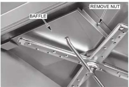
In addition to normal cleaning, the baffles, located on the upper chamber on the inside of the machine, may need periodic cleaning. Note that the PW20n models will have two sets of baffles.
⚠ WARNING Disconnect the electrical power to the machine and follow lockout / tagout procedures. There may be multiple circuits. Be sure all circuits are disconnected.
- Loosen and remove the nut from the baffle and remove the baffle by sliding the tab out of the retainer.
text_image
BAFFLE REMOVE NUTFig. 23
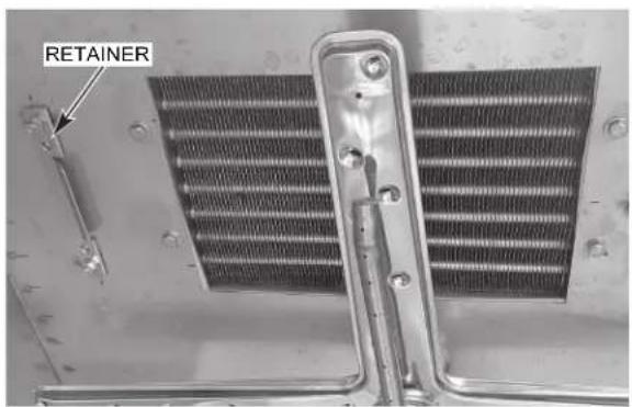
text_image
RETAINERFig. 24
- Debris may collect on the top surface of baffles and should be washed in a sink with mild detergent and rinsed.
- Replace all removed parts.
- Leave machine door open to allow interior to air out and dry.
TROUBLESHOOTING
ERROR CODE CHART WITH POSSIBLE SOLUTIONS
| Error No. | Text On Screen Error | Description Troubleshooting | |
| 001 | Booster Thermistor Error.Drain Machine, Call Service. | The booster temperature is 239°F (115°C) or greater. | Press and hold the power button for 5 seconds to clear the error. The machine will drain and power off. If the error persists, contact Hobart Service. |
| 002 | Booster Thermistor Error.Drain Machine, Call Service. | The booster temperature is 32°F (0°C) or lower. | Press and hold the power button for 5 seconds to clear the error. The machine will drain and power off. If the error persists, contact Hobart Service. |
| 003 | Booster Temperature Not Reached During Fill Cycle. | During the fill cycle, the booster temperature did not meet the setpoint within the predetermined time. | Press the ENTER button to clear the error. If the error persists, contact Hobart Service. |
| 004 | Booster Temperature Not Reached During Wash Cycle. | During the wash cycle, the booster temperature did not meet the setpoint within the predetermined time. | Press the ENTER button to clear the error. If the error persists, contact Hobart Service. |
| 006 | Sump Thermistor Error.Drain Machine, Call Service. | The wash tank temperature is 239°F (115°C) or greater. | Press and hold the power button for 5 seconds to clear the error. The machine will drain and power off. If the error persists, contact Hobart Service. |
| 007 | Sump Thermistor Error.Drain Machine, Call Service. | The wash tank temperature is 32°F (0°C) or lower. | Press and hold the power button for 5 seconds to clear the error. The machine will drain and power off. If the error persists, contact Hobart Service. |
| 008 | Wash Tank TemperatureNot Reached During Fill Cycle. | During the fill cycle, the wash tank temperature did not meet the setpoint within the predetermined time. | Press the ENTER button to clear the error. If the error persists, contact Hobart Service. |
| 014 | Booster Pressure Error.Drain Machine, Call Service. | The maximum booster water level has been exceeded. The machine will not run. | Press and hold the power button for 5 seconds to clear the error. The machine will drain and power off. If the error persists, contact Hobart Service. |
| 015 | Booster Pressure Error.Drain Machine, Call Service. | The minimum booster water level has not been reached. The machine will not run. | Press and hold the power button for 5 seconds to clear the error. The machine will drain and power off. If the error persists, contact Hobart Service. |
| 016 | Wash Tank Pressure Error. Drain Machine, Call Service. | The maximum wash tank water level has been exceeded. The machine will not run. | Press and hold the power button for 5 seconds to clear the error. The machine will drain and power off. If the error persists, contact Hobart Service. |
| 017 | Wash Tank Pressure Error. Drain Machine, Call Service. | The minimum wash tank water level has not been reached. The machine will not run. | Press and hold the power button for 5 seconds to clear the error. The machine will drain and power off. If the error persists, contact Hobart Service. |
| 018 W | Wash Tank Water Level is Too High. Machine Draining. | Wash tank water level is above the upper limit. | Press and hold the manual drain button for 5 seconds to drain the unit back to normal level. Press the ENTER button if displayed to clear the error. If the ENTER button does not display, press and hold the power button for 5 seconds. Machine will drain and power off. If the error persists, contact Hobart Service. |
| 020 R | Rinse System Error. Check and Clean Rinse Arms. | The wash tank water level did not increase by the anticipated amount after being filled by the rinse cycle. | Press the ENTER button to clear the error. The machine will drain and clear the error. Ensure tank is clean. If the error persists, contact Hobart Service. |
| 021 D | Drain Hose is Clogged. Clean Drain Hose and Drain Machine Again. | Significant water remains in wash tank after drain cycle. | Ensure power to machine is off and wash water has cooled. Verify standpipe and bottom of wash tank are free of debris. Clean the drain hose and drain the machine. Ensure drain hose is not kinked and installed properly. If error remains on screen, press and hold the power button for 5 seconds to clear the error. Machine will drain and power down. |
| 022 D | Drain System Error. During wash cycle, water level not maintained at normal level. | Ensure power to machine is off and wash water has cooled. Verify standpipe and bottom of wash tank are free of debris. Clean the drain hose and drain the machine. Ensure drain hose is not kinked and installed properly. If error remains on screen, press the ENTER button to clear the error. | |
| 023 R | Rapid Fill System Timeout. Inspect Incoming Water Line. | The fill valve has been active for more than the maximum allowed fill time, and the wash tank water level has not been reached. This error will only occur if unit is equipped with rapid fill. | Ensure incoming water supply is turned on and that fill hose is not kinked. Verify water pressure is 15 - 65 psi. Press the ENTER button to clear the error. If the error persists, contact Hobart Service. |
| 029 P | Program Interrupted. Close Door. | Door is opened during machine operation. | Close the door and ensure door is fully seated. The current operation resumes. If the error persists, contact Hobart Service. |
| 032 F | Fill Error, Inspect Incoming Water Line. | The booster water level did not reach the proper level within the set amount of time. | Ensure incoming water supply is turned on and that fill hose is not kinked. Verify water pressure is 15 - 65 psi. Press the ENTER button to clear the error. If the error persists, contact Hobart Service. |
| 033 B | Booster Fill Error, Check Incoming Water Line. | The fill valve has been active for more than the maximum allowed fill time. | Ensure incoming water supply is turned on and that fill hose is not kinked. Verify water pressure is 15 - 65 psi. Press the ENTER button to clear the error. If the error persists, turn water supply off and contact Hobart Service. |
| 038 In | Incoming Power to Machine is Too High. Machine Has Powered Down. | The incoming voltage is higher than the maximum required machine voltage. | The incoming voltage must be at or below the required machine voltage (see machine data plate). Turn circuit breaker supply off and ensure unit is connected with proper voltage supply. Press Enter to clear error. |
| 039 Fill Cycle Interrupted. Close Door. | Door is opened during the fill cycle. | Close the door and ensure door is fully seated. The fill cycle resumes. If the error persists, contact Hobart Service. | |
| 049 C | Communication Between the Controls Has Been Interrupted. | Interruption of communication between control board and touchscreen display. | Communication between the controls should be automatically restored. If the problem persists, contact Hobart Service. |
| 052 D | Drain System Error. Check Drain Pump and Hose. | Wash tank water level is above the upper limit. | Ensure power to machine is off and wash water has cooled. Verify standpipe and bottom of wash tank are free of debris. Clean the drain hose and drain the machine. Ensure drain hose is not kinked and installed properly. If error remains on screen, press and hold the power button for 5 seconds to clear the error. Machine will drain and power down. |
| 057 W | Wash Tank is Filling. Cycle Will Begin When Water is Replenished. | Wash tank water level is low at start of wash cycle. | Machine automatically fills while error is displayed. Once proper water level is reached, wash cycle will begin. |
| 081 F | Final Rinse Thermistor Error. | Final rinse temperature is 239^ (115^) or greater. | Press and hold the power button for 5 seconds to clear the error. The machine will drain and power off. If the error persists, contact Hobart Service. |
| 082 F | Final Rinse Thermistor Error. | Final rinse temperature is 32^ (0^) or lower. | Press and hold the power button for 5 seconds to clear the error. The machine will drain and power off. If the error persists, contact Hobart Service. |
| 085 W | Wash Tank Overtemp Tripped. | Wash tank overtemp has been tripped. | Error cannot be cleared until overtemp has been reset. Contact Hobart Service. |
| 086 B | Booster Overtemp Tripped. | Booster overtemp has been tripped. | Error cannot be cleared until overtemp has been reset. Contact Hobart Service. |
| 088 A | Alert: Wash Tank Contactor Fault. Pull Circuit Breaker(s) and Contact Service. | Wash tank heater remains on while ignoring software command to turn off. | Machine is running a fill and drain cycle to protect the heater. This error is not user serviceable. Turn circuit breaker supply(s) off and contact Hobart Service. |
| 089 A | Alert: Booster Contactor Fault. Pull Circuit Breaker(s) and Contact Service. | Booster heater remains on while ignoring software command to turn off. | Machine is running a fill and drain cycle to protect the heater. This error is not user serviceable. Turn circuit breaker supply(s) off and contact Hobart Service. |
| 097 D | Detergent Supply Empty. Replace Detergent. | Detergent has not been sensed for two consecutive cycles. | Ensure detergent is present in bottle and that cap & tube are properly secured to bottle. Replace detergent bottle if empty. Press the ENTER button to clear the error. |
| 098 D | Detergent Supply Empty. Press Power Button to Drain Machine and Power Down. | Detergent has not been sensed for two consecutive cycles. The machine will be locked out until the detergent has been replaced. | Ensure detergent is present in bottle and that cap & tube are properly secured to bottle. Replace detergent bottle if empty. Press and hold the power button for 5 seconds to clear the error. The machine will drain and power off. If the error persists, contact Hobart Service. |
| SYMPTOM POSSIBLE | CAUSE |
| No machine operation. | 1. Machine off, turn machine on.2. Blown fuse or tripped circuit breaker at power supply. |
| Ware spotted or not clean. | 1. Loss of water pressure due to pump obstruction. Power machine off to drain tank. ▲WARNING Disconnect electrical power supply (both dishwasher and booster if applicable). Check for obstructions at strainer pans, scrap basket and pump intake.2. Incorrect wash and/or final rinse temperature. Contact Service for adjustment or repair.3. Excessive mineral deposits throughout wash and rinse system. Delime unit as required.4. Check wash and rinse arms to ensure there are no obstructions and ensure they rotate properly.5. Strainers clogged causing inadequate water supply to pump; clean machine according to Cleaning section, page 22.6. Incorrect or insufficient detergent and/or rinse aid for water condition or soil load or chemical dispenser is not working properly. Contact chemical supplier.7. Excessive soil; scrap dishes before cycle. Ensure wash tank is drained and cleaned as required.8. Improper loading of ware. Do not overload machine. |
| Inadequate rinse or rinse water temperature too low. | 1. Excessive mineral deposits throughout wash and rinse system. Delime unit as required.2. For non-ventless machines, incoming water temperature to booster below 110°F. For ventless machines, incoming water temperature to machine below 55°F. Machine will automatically extend wash time until booster heats up.3. Obstruction in rinse arms. Ensure rinse arms rotate freely. |
| Leaking valve. | 1. If hose connection at valve is leaking, check hose gasket to ensure it is seated properly and not worn or cut.2. Malfunctioning solenoid valve (leaking or not closing). Contact Hobart Service. |
| Low / no wash tank heat. | 1. Malfunctioning tank heater or overtemp tripped. Contact Hobart Service.2. Ensure heating element is clean and free of excessive lime scale. Delime unit as required. |
| No or slow fill. | 1. Water supply may be off; ensure hot water supply valve is open.2. Dirty strainer at fill hose connection causing reduced water flow. Turn off hot water supply, remove fill hose and clean screen. Reassemble. |
| Excessive steam or water vapor after cycle is complete - PW10n-ADV, PW10n-ADVSW, PW20n-ADV, PW12n-ADV and PW12n-ADVSW models only. | 1. Incoming cold water too warm. Contact Hobart Service for adjustment of condensing cycle time. |
SERVICE
PWn EXPENDABLE PARTS
The below PWN prep washer parts are expendable by nature and may not be covered by Hobart Product Warranty. To view the Hobart Product Warranty, refer to https://www.hobartservice.com/service-plans/hobart-product-warranty.
PWn EXPENDABLE PARTS LIST
| Part Number Description Qty. Machine Type | |||
| 00-443581 USB plug 1 All | |||
| 00-913102-529 Service kit, wash arm (includes wash arm plugs kit, wash arm guide, wash arm nut and o-rings) | 1 All | ||
| 01-605145 Kit, wash arm plug 1 All | |||
| 00-324751 Retaining ring (wash arm) AR All | |||
| 00-185112 | Standpipe (delime) | 1 Advansys | |
| 00-185105-00029 | Tubing, black, 144" | 1 Advansys | |
| 00-113156-00001 | Clamp (spring action hose) | AR Advansys | |
| 00-949014 Roller, conveyor rack | AR PW/20n/PW/12n | ||
Contact your local Hobart-authorized service office for any repairs or adjustments needed on this equipment. Long-term service contracts are available on this and other Hobart products. Call 1-888-4HOBART for Hobart Service 24 hours a day.

text_image
IN MO N D E R U C T D, E M P L O N S UCC C I O N E SLAVE-BATTERIE PW10n/PW20n/PW12n

MODÈLE
PW10n-BAS
PW10n-ADV
PW10n-ADVSW
PW20n-BAS
PW20n-ADV
PW12n-ADV
PW12n-ADVSW
natural_image
Exterior view of a modern stainless steel industrial oven (no visible text or symbols)HOBART
701 S. RIDGE AVENUE
TROY, OHIO 45374-0001
937 332-3000
www.hobartcorp.com
F-41318 (Mars 2025)
natural_image
Exterior view of a modern stainless steel industrial oven with dual doors and control panel (no visible text or symbols)Modèle PW20n-ADV
natural_image
Exterior view of a modern stainless steel industrial oven with three-tiered doors and control panels (no visible text or symbols)natural_image
Exterior view of a modern stainless steel laboratory oven with control panel and digital display (no visible text or symbols)TABLE DES MATIÈRES
GÉNÉRAL 4
INSTALLATION....4
Déballage 5
Retirer la machine de la pallette....5
text_image
Technical diagram of a heat exchanger or cooling unit with numbered components and directional arrows indicating parts.Fig. 4
natural_image
Interior view of a mechanical or electronic device with two central chambers and visible wiring (no text or symbols)Fig. 5
natural_image
Close-up of an electrical control panel with wiring and components (no visible text or symbols)natural_image
Interior view of an industrial equipment setup with a motor, tubing, and a container (no visible text or symbols)PW10n-BAS / PW10n-ADV / PW10n-ADVSW / PW12n-ADV / PW12n-ADVSW (VU DE L'ARRIÈRE)
Fig. 13
PW20n-BAS / PW20n-ADV
natural_image
Close-up of a mechanical device with visible wiring and components, no readable text or symbols present.PW20n-BAS / PW20n-ADV
(VU DU CÔTÉ GAUCHE)
Fig. 14
IN MO N D E U C T D, E M O N S C I O L O I N E S
LAVAVAJILLASPW10n, PW20n Y PW12n

MODELOS
PW10n-BAS
PW10n-ADV
PW10n-ADVSW
PW20n-BAS
PW20n-ADV
PW12n-ADV
PW12n-ADVSW
natural_image
Exterior view of a modern stainless steel industrial oven with control panel and digital display (no visible text or symbols)HOBART
701 S. RIDGE AVENUE
TROY, OHIO 45374-0001
937 332-3000
www.hobartcorp.com
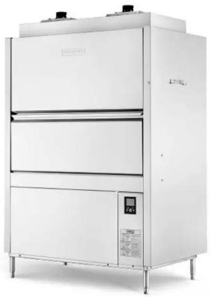
Modelo PW10n-BAS Modelo PW10n-ADV / PW10n-ADVSW
natural_image
Exterior view of a modern stainless steel industrial refrigerator with control panel and display (no visible text or symbols)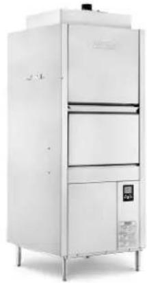
natural_image
Exterior view of a modern stainless steel industrial oven with control panel and digital display (no visible text or symbols)Modelo PW20n-BAS
natural_image
Exterior view of a modern stainless steel industrial oven or refrigerator unit (no visible text or symbols)Modelo PW20n-ADV
natural_image
Exterior view of a modern white industrial oven or processing unit (no visible text or symbols)natural_image
Exterior view of a stainless steel industrial oven with control panel and digital display (no visible text or symbols)ÍNDICE
INDICACIONES GENERALES....4
INSTALACIÓN 5
Desembalaje....5
natural_image
Close-up of industrial equipment with hoses and cables, no visible text or symbolsDESCONECTE LA MANGUERA DE LLENADO
PARA VACIAR EL AGUA DE LA BOBINA
Fig. 2
text_image
Labeled diagram of a heat exchanger or cooling unit with numbered components and directional arrows indicating parts.Fig. 4
natural_image
Interior view of an electronic device with visible circuitry and wiring (no text or symbols)Fig. 5
natural_image
Interior view of an electrical control panel with wiring and components (no visible text or symbols)natural_image
Interior view of an industrial machine with visible wiring and components (no text or symbols)W10n-BAS / PW10n-ADV / PW10n-ADVSW / PW12n-ADV / PW12n-ADVSW (VISTA POSTERIOR)
Fig. 13
PW20 y PW20eR
natural_image
Close-up of a mechanical device with visible wiring and control buttons (no readable text or symbols)PW20n-BAS / PW20n-ADV
(VISTA IZQUIERDA)
Fig. 14
https://www.hobartservice.com/service-plans/hobart-product-warranty.
LISTA DE PIEZAS FUNGIBLES DEL PWn