
ECU-1370 - Industrial computer Advantech - Free user manual and instructions
Find the device manual for free ECU-1370 Advantech in PDF.

| Brand | Advantech |
| Model | ECU-1370 |
| Category | Industrial computer |
| Power supply | 10 to 30 VDC, 1.5 to 0.5 A (UL certified source, SELV compliance) |
| Storage temperature | -30 °C to 70 °C |
| Maximum ambient temperature | 70 °C |
| Equipment type | Open type, must be installed in a suitable enclosure |
| Cleaning | Damp cloth only, without liquid or sprayed detergent |
| Safety | Do not open; refer all servicing to qualified personnel |
| Battery | Danger of explosion if replaced incorrectly; use the same type or equivalent recommended |
| Ventilation | Do not obstruct convection openings |
| Usage | Indoor non-polluted environment, out of reach of children |
| Ground connection | Mandatory grounded power outlet |
| Repairability | No user-serviceable parts; return to manufacturer |
| Liquid protection | Do not pour liquid into openings |
| Power pins (41-54) | Connection to a PS2 or LPS circuit, less than 100 W according to IEC 62368-1 |
Frequently Asked Questions - ECU-1370 Advantech
User questions about ECU-1370 Advantech
0 question about this device. Answer the ones you know or ask your own.
Ask a new question about this device
Download the instructions for your Industrial computer in PDF format for free! Find your manual ECU-1370 - Advantech and take your electronic device back in hand. On this page are published all the documents necessary for the use of your device. ECU-1370 by Advantech.
USER MANUAL ECU-1370 Advantech
natural_image
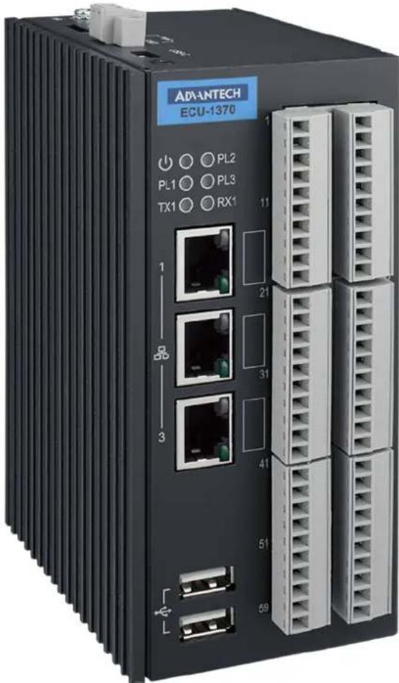
Illustration of three stacked electronic devices with no visible text or symbolsECU-1370
Copyright
The documentation and the software included with this product are copyrighted 2024 by Advantech Co., Ltd. All rights are reserved. Advantech Co., Ltd. reserves the right to make improvements in the products described in this manual at any time without notice. No part of this manual may be reproduced, copied, translated, or transmitted in any form or by any means without the prior written permission of Advantech Co., Ltd. The information provided in this manual is intended to be accurate and reliable. However, Advantech Co., Ltd. assumes no responsibility for its use, nor for any infringements of the rights of third parties that may result from its use.
Acknowledgments
Intel, Pentium, Celeron and Atom are trademarks of Intel Corporation.
Microsoft Windows and MS-DOS are registered trademarks of Microsoft Corp.
All other product names or trademarks are properties of their respective owners.
Support
For more information on this and other Advantech products, please visit our websites at: http://www.advantech.com
For technical support and service, please visit our support website at: http://www.advantech.com/support/
Part No. 2003137000 Edition 1
Printed in China June 2024
Product Warranty (2 years)
Advantech warrants the original purchaser that each of its products will be free from defects in materials and workmanship for two years from the date of purchase.
This warranty does not apply to any products that have been repaired or altered by persons other than repair personnel authorized by Advantech, or products that have been subject to misuse, abuse, accident, or improper installation. Advantech assumes no liability under the terms of this warranty as a consequence of such events.
Because of Advantech's high quality-control standards and rigorous testing, most customers never need to use our repair service. If an Advantech product is defective, it will be repaired or replaced free of charge during the warranty period. For out-of-warranty repairs, customers will be billed according to the cost of replacement materials, service time, and freight. Please consult your dealer for more details.
If you believe your product is defective, follow the steps outlined below.
- Collect all the information about the problem encountered. (For example, CPU speed, Advantech products used, other hardware and software used, etc.) Note anything abnormal and list any onscreen messages displayed when the problem occurs.
- Call your dealer and describe the problem. Please have your manual, product, and any helpful information readily available.
- If your product is diagnosed as defective, obtain a return merchandise authorization (RMA) number from your dealer. This allows us to process your return more quickly.
- Carefully pack the defective product, a completed Repair and Replacement Order Card, and a proof of purchase date (such as a photocopy of your sales receipt) into a shippable container. Products returned without a proof of purchase date are not eligible for warranty service.
- Write the RMA number clearly on the outside of the package and ship the package prepaid to your dealer.
Declaration of Conformity
CE
This product has passed the CE test for environmental specifications when shielded cables are used for external wiring. We recommend the use of shielded cables. This type of cable is available from Advantech. Please contact your local supplier for ordering information.
Test conditions for passing also include the equipment being operated within an industrial enclosure. In order to protect the product from damage caused by electrostatic discharge (ESD) and EMI leakage, we strongly recommend the use of CE-compliant industrial enclosure products.
FCC Class A
This equipment has been tested and found to comply with the limits for a Class A digital device, pursuant to part 15 of the FCC Rules. These limits are designed to provide reasonable protection against harmful interference when the equipment is operated in a commercial environment. This equipment generates, uses, and can radiate radio frequency energy and, if not installed and used in accordance with the instruction manual, may cause harmful interference to radio communications. Operation of this equipment in a residential area is likely to cause harmful interference. In this event, users are required to correct the interference at their own expense.
UL
This product has passed the UL test for audio/video, information and communication technology equipment Part 1: Safety requirements.
Technical Support and Assistance
- Visit the Advantech website at www.advantech.com/support to obtain the latest product information.
- Contact your distributor, sales representative, or Advantech's customer service center for technical support if you need additional assistance. Please have the following information ready before calling:
– Product name and serial number
– Description of your peripheral attachments
– Description of your software (operating system, version, application software, etc.)
– A complete description of the problem
– The exact wording of any error messages
Safety Instructions
- Read these safety instructions carefully.
- Retain this user manual for future reference.
- Disconnect the equipment from all power outlets before cleaning. Use only a damp cloth for cleaning. Do not use liquid or spray detergents.
-
For pluggable equipment, the power outlet socket must be located near the equipment and easily accessible.
-
Protect the equipment from humidity.
-
Place the equipment on a reliable surface during installation. Dropping or letting the equipment fall may cause damage.
-
The openings on the enclosure are for air convection. Protect the equipment from overheating. Do not cover the openings.
-
Ensure that the voltage of the power source is correct before connecting the equipment to a power outlet.
-
Position the power cord away from high-traffic areas. Do not place anything over the power cord.
-
All cautions and warnings on the equipment should be noted.
-
If the equipment is not used for a long time, disconnect it from the power source to avoid damage from transient overvoltage.
-
Never pour liquid into an opening. This may cause fire or electrical shock.
-
Never open the equipment. For safety reasons, the equipment should be opened only by qualified service personnel.
-
If any of the following occurs, have the equipment checked by service personnel:
-
The power cord or plug is damaged.
– Liquid has penetrated the equipment.
– The equipment has been exposed to moisture. -
The equipment is malfunctioning, or does not operate according to the user manual.
– The equipment has been dropped and damaged.
– The equipment shows obvious signs of breakage. -
DO NOT LEAVE THIS EQUIPMENT IN AN ENVIRONMENT WHERE THE STORAGE TEMPERATURE MAY GO BELOW -30°C (-22°F) OR ABOVE 70°C (158°F). THIS COULD DAMAGE THE EQUIPMENT. THE EQUIPMENT SHOULD BE IN A CONTROLLED ENVIRONMENT.
-
CAUTION: DANGER OF EXPLOSION IF BATTERY IS INCORRECTLY REPLACED. REPLACE ONLY WITH THE SAME OR EQUIVALENT TYPE RECOMMENDED BY THE MANUFACTURER, DISCARD USED BATTERIES ACCORDING TO THE MANUFACTURER'S INSTRUCTIONS.
-
This product is intended to be supplied by an UL certified power supply or dc source with SELV output, rated 10 to 30Vdc, 1.5 to 0.5A minimum and maximum ambient temperature (Tma) 70 degree C minimum without power source or adapter. If you need further assistance, please contact Advantech for further information.
-
Ensure that the voltage of the power source is correct before connecting the equipment to a power outlet. The power outlet socket should have a grounded connection.
-
For use in pollution free environments and indoor use.
-
This equipment is not suitable for use in locations where children are likely to be present.
-
If the equipment is used in a manner not specified by the Advantech, the protection provided by the equipment may be impaired.
- The equipment contains no user-serviceable parts. Do not open, Return to manufacturer for servicing.
- Do not block air ventilation holes.
- This is open type equipment and should be installed in a suitable enclosure.
Safety Precaution - Static Electricity
Follow these simple precautions to protect yourself from harm and the products from damage.
To avoid electrical shock, always disconnect the power from the PC chassis before manual handling. Do not touch any components on the CPU card or other cards while the PC is powered on.
■ Disconnect the power before making any configuration changes. A sudden rush of power after connecting a jumper or installing a card may damage sensitive electronic components.
Contents
Chapter 1 Overview......1
1.1 Introduction ...... 2
1.2 Specifications.... 3
1.2.1 General 3
1.2.2 System....3
1.2.3 Digital Input.... 3
1.2.4 Relay Output.... 4
1.2.5 Ethernet 4
1.2.6 RS485 4
1.2.7 CAN 4
1.2.8 1-Wire Master 4
1.2.9 Output Voltage....4
1.2.10 Software & Firmware 4
1.2.11 SSH Login User Name & Password 5
1.2.12 Default IP 5
1.3 Chassis Dimensions....5
Figure 1.1 ECU-1370 Chassis Dimensions .... 5
1.4 Packing List.... 5
Chapter 2 Hardware Functionality......7
2.1 Overview 8
Figure 2.1 ECU-1370 Overview....8
2.2 LED Status Indicators 9
2.2.1 System Status Indicators 9
Figure 2.2 System Status Indicator....9
Table 2.1: System LED Definition....9
2.2.2 Ethernet Status Indicator 9
Table 2.2: Ethernet LED Definition....9
Chapter 3 Wiring and Installation .....11
3.1 Wiring.... 12
3.1.1 Power Supply.... 12
Figure 3.1 Power Supply 12
Table 3.1: AC/DC Power Input Connector Pin Definition ..... 12
3.1.2 Console Port 12
Figure 3.2 Console Port (USB-C) 12
3.1.3 USB Ports 12
Figure 3.3 USB Ports....12
Table 3.2: USB Connector Pin Assignment.... 12
3.1.4 Ethernet Ports.... 13
Figure 3.4 LAN Connectors (LAN1\~LAN3).... 13
Table 3.3: LAN Connector Pin Assignments 13
3.1.5 SD Card Slot.... 13
Figure 3.5 SD Card Slot.... 13
3.1.6 Multi-Functional Ports (Screw Terminal).... 14
Figure 3.6 Multi-Functional Ports.... 14
3.2 Switch and Jumper Setting 15
3.2.1 Motherboard SW2 Setting.... 15
Figure 3.7 Motherboard Switch 2 Setting 15
Table 3.4: Motherboard SW2 Setting 15
3.2.2 IOboard Jumper Setting.... 16
Figure 3.8 IOboard Jumper Setting 16
Table 3.5: IOboard Jumper Setting 16
3.3 Installation.... 17
3.3.1 DIN-Rail Installation.... 17
Figure 3.9 Vertical DIN-Rail Bracket Installation .... 17
Chapter 1
Overview
1.1 Introduction
The ECU-1370 is a high-performance IoT gateway based on the i.MX8M platform. Featuring an open design with a Quad-Core processor, it includes three 10/100/1000 Ethernet ports, multiple communication and DIO ports, and an operating temperature range of -40 to 80°C. Running on the Ubuntu 22.04 operating system, the ECU-1370 allows system integrators to develop applications specifically for solar power, electricity generation, and factory settings that require extensive cloud-based data collection. This makes the ECU-1370 an excellent solution for energy storage systems.
1.2 Specifications
1.2.1 General
Line Power Input: 24V DC (10\~30V DC /1.5\~0.5A), 2-pin screw terminal
■ Reverse Polarity Protection: YES
■ Power Overvoltage Protection: 37 V _DC within 1sec.
■ Under Voltage Lock Out: 10.5 V DC
■ Over Voltage Lock Out: 29 V DC
- Operating Temperature: -40^ to 80^
■ Storage Temperature: -40^ to 80^
■ Operating Humidity rating: 95% non-condensing
■ Protection Class: IP30
■ Dimensions: 93mm (D) x 65.7mm(W) x 140mm(H)
■ Mounting: Din Rail
1.2.2 System
■ CPU: NXP MIMX8MQ6CVAHZAB (Quad core 1.3G)
■ Memory: 4GB LPDDR4
Storage: 32GB eMMC
USB: 2 x USB2.0
■ LED: 1 x PWR, 3 x Programmable, TX1, RX1
■ LAN: 3 x 10/100/1000 Base-T
■ Watch Dog Timer: YES
RTC: YES
■ Serial Communication: 1 x RS-485
1 x Single-Channel 1-Wire Master
1 x CANBus (ISO 11898-2)
■ Console Port: 1 x USB-Type C, 115200bps
1.2.3 Digital Input
Channel: 24
■ Connectors Type: Terminal blocks
■ Input Filter: Programmable, Default 3ms
■ Pulse Input Frequency: 150Hz
Wet Contact
- Logic level 0: 0\~3.3V
- Logic level 1: 9\~26V
LED State: NO
1.2.4 Relay Output
Channel: 6
■ Connectors Type: Terminal blocks
■ Relay Type: 4 x Form A, 2 x Form C
■ Contact Rating: 30 V DC @ 3A
■ Mechanical endurance: 1 × 10^7 operations
Isolation between open contacts: 750VAC for 1 minute
■ Flyback diode: YES
■ Relay On Time: 10 ms
■ Relay Off Time: 5 ms
■ Insulation Resistance: 100MΩ min. at 500 V DC
LED State: NO
1.2.5 Ethernet
Connectors: 3 x RJ-45
■ Speed: 10/100/1000 Base-T
■ LED State: Green (Link)/Orange or Green (Speed)
1.2.6 RS485
Channel: 1
■ Connectors Type: Terminal blocks
■ Wiring: 2-wired (D+, D-, GND)
LED State: TX1/RX1
■ Baud Rate: 300 bps to 921.6 Kbps
1.2.7 CAN
Channel: 1
■ Connectors Type: Terminal Blocks
■ Wiring: 2-wired (CAN+, CAN-, GND)
Baud Rate:
– High Speed CAN: 40 Kbps to 1 Mbps
– Low Speed/Fault Tolerant CAN: 40 Kbps to 125 Kbps
1.2.8 1-Wire Master
■ Channel: 1 (maxim integrated, DS2482-100)
■ Connectors Type: Terminal Blocks
Wiring: 1-wired
Isolation: YES
1.2.9 Output Voltage
■ Channel: 1 x 5V DC @ 1W
■ Connectors Type: Terminal Blocks
1.2.10 Software & Firmware
Operation System: Ubuntu 22.04, Kernel 5.X
I/O FW/Driver: ver: 01010101
OTA: YES
1.2.11 SSH Login User Name & Password
User Name: root
■ Password: no password ( Just press "Enter")
1.2.12 Default IP
Default is DHCP mode and if there's no DHCP server connected, will turn to IP as below.
■ LAN1: 10.0.0.1
■ LAN2: 11.0.0.1
■ LAN3: 12.0.0.1
1.3 Chassis Dimensions
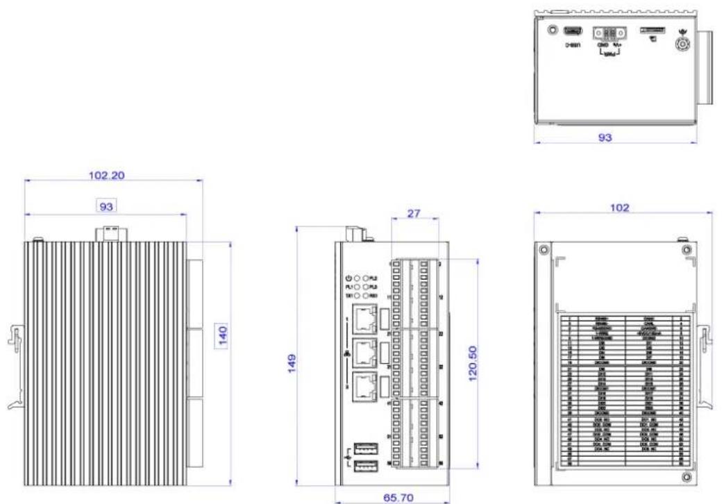
Figure 1.1 ECU-1370 Chassis Dimensions
1.4 Packing List
The accessory package of ECU-1370 contains the following items:
(A) ECU-1370
(B) Connector
(C) Din-rail
Chapter 2
Hardware
Functionality
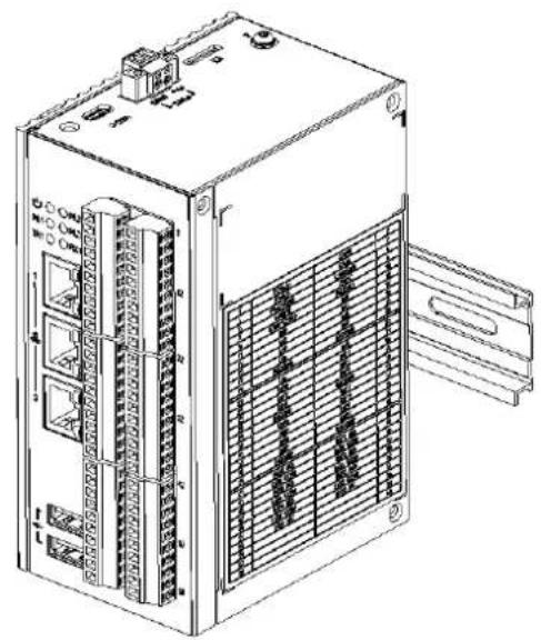
2.1 Overview
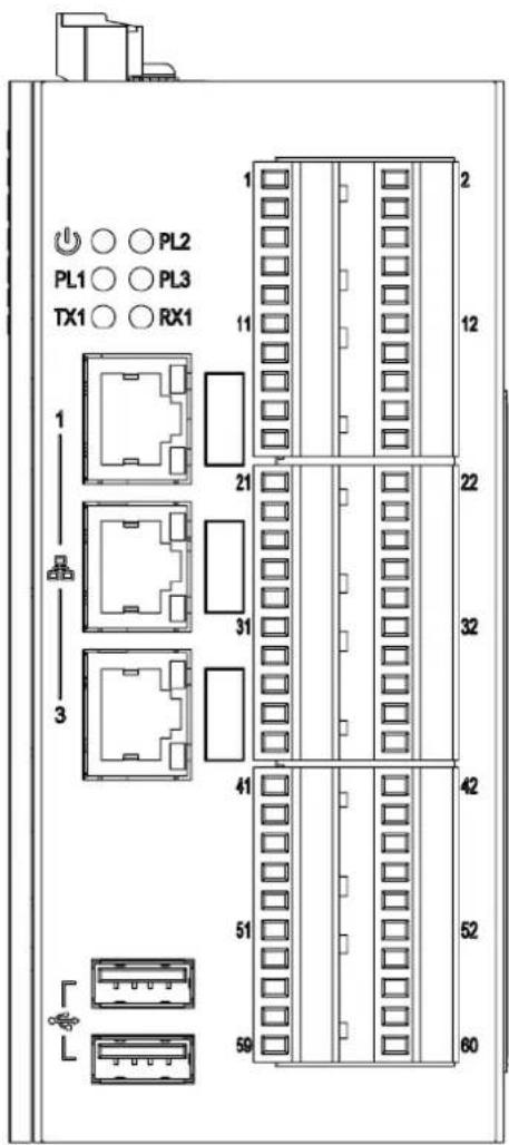
Figure 2.1 ECU-1370 Overview
2.2 LED Status Indicators
2.2.1 System Status Indicators
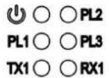
Figure 2.2 System Status Indicator
Table 2.1: System LED Definition
| LED Status Description | ||
| PWR | Green Power is on | |
| Off Power is off | ||
| PLX | Green | Customers can define the Programmable LED state according to the application. |
| Off | ||
| TX1 | Green RS485 data being transmitted | |
| Off No data being transmitted | ||
| RX1 | Green RS485 data being received | |
| Off No data being received | ||
2.2.2 Ethernet Status Indicator

Table 2.2: Ethernet LED Definition
| Speed\LED Link Act | ||
| No Connection Off Off | ||
| 10 MBit Off Green/Blinking | ||
| 100 MBit | Orange | Green/Blinking |
| 1000 MBit | Green | Green/Blinking |
Chapter 3
Wiring and Installation
3.1 Wiring
3.1.1 Power Supply
ECU-1370 supports power input ranging from 10 to 30VDC. The terminal block is suitable for 16-26 AWG, Torque value 3 Lb In. Use copper conductors only. Must be installed by skilled personnel.
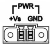
Figure 3.1 Power Supply
Table 3.1: AC/DC Power Input Connector Pin Definition
Function Pin Screen Printing Function Description
| Power Input 1 +Vs PWR V+ DC power input PIN | |
| 2 GND | PWR V- DC power input PIN |
3.1.2 Console Port
USB-C

Figure 3.2 Console Port (USB-C)
3.1.3 USB Ports

Figure 3.3 USB Ports
Table 3.2: USB Connector Pin Assignment
| Pin | Signal |
| 1 | VCC |
| 2 | DATA- |
| 3 | DATA+ |
| 4 | GND |
3.1.4 Ethernet Ports

Figure 3.4 LAN Connectors (LAN1\~LAN3)
Table 3.3: LAN Connector Pin Assignments
| Pin Description 10Mbit 100Mbit 1000Mbit | ||||
| 1 Transmit Data+ or Bidirectional TX+ TX+ BI_DA+ | ||||
| 2 Transmit Data- or Bidirectional TX- TX- BI_DA- | ||||
| 3 Receive Data+ or Bidirectional RX+ | RX+ | BI_DB+ | ||
| 4 | Not connected or Bidirectional | N/C | N/C | BI_DC+ |
| 5 | Not connected or Bidirectional | N/C | N/C | BI_DC- |
| 6 | Receive Data- or Bidirectional | RX- | RX- | BI_DB- |
| 7 | Not connected or Bidirectional | N/C | N/C | BI_DD+ |
| 8 | Not connected or Bidirectional | N/C | N/C | BI_DD- |
3.1.5 SD Card Slot
ECU-1370 is equipped with a SD card interface on the top.
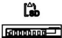
Figure 3.5 SD Card Slot
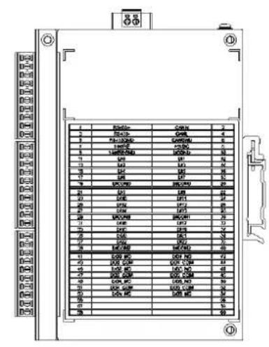
3.1.6 Multi-Functional Ports (Screw Terminal)
Caution! Pin 41 to Pin 54 only suitable for connecting to PS2 or LPS circuit, less than 100W, according to IEC 62368-1.

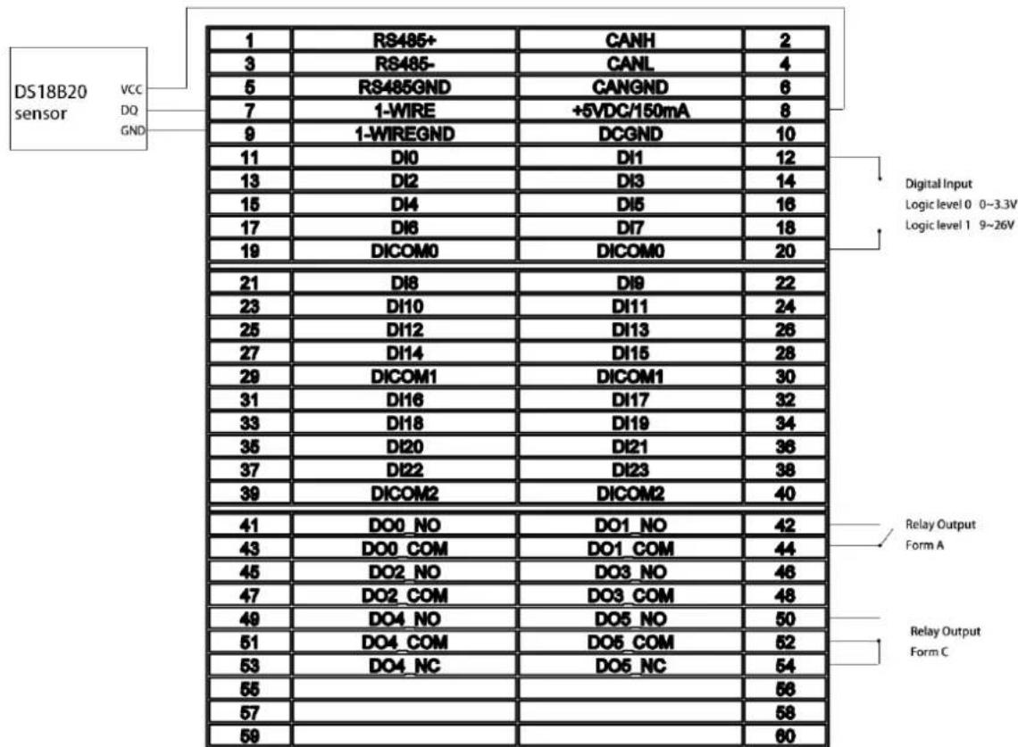
Figure 3.6 Multi-Functional Ports
3.2 Switch and Jumper Setting
3.2.1 Motherboard SW2 Setting
The motherboard of ECU-1370 has a switch to select boot device.
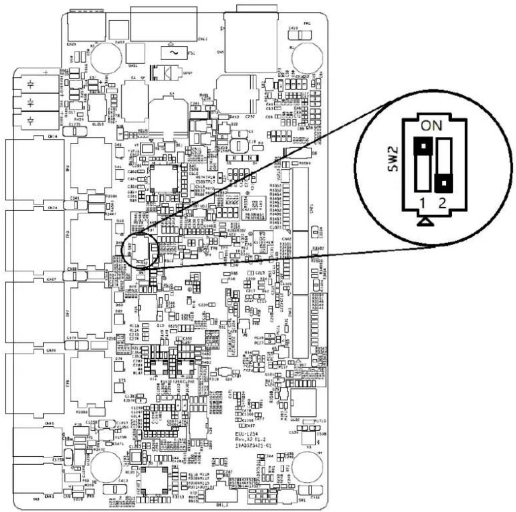
Figure 3.7 Motherboard Switch 2 Setting
Table 3.4: Motherboard SW2 Setting
Function Pin Function Description
| Boot mode | 1 ON 2 OFF Boot from eMMC (Default) |
| 1 OFF 2 ON Boot from SD card |
3.2.2 IOboard Jumper Setting
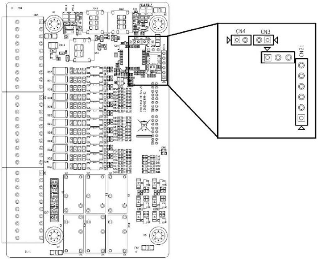
Figure 3.8 IOboard Jumper Setting
Table 3.5: IOboard Jumper Setting
| Function Pin Function Description |
| Console port CN2 OFF (Default) |
| Watch Dog CN3 ON (Default) |
| Download FW CN4 OFF (Default) |
| Download FW (Debug) CN21 OFF (Default) |
3.3 Installation
3.3.1 DIN-Rail Installation
ECU-1370 supports DIN-Rail installation. The detailed steps are shown as below:
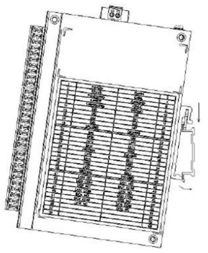
natural_image
Technical line drawing of an industrial electronic device with multiple ports and a grid panel (no text or symbols)Figure 3.9 Vertical DIN-Rail Bracket Installation
www.advantech.com
Please verify specifications before quoting. This guide is intended for reference purposes only.
All product specifications are subject to change without notice.
No part of this publication may be reproduced in any form or by any means, electronic, photocopying, recording or otherwise, without prior written permission of the publisher.
All brand and product names are trademarks or registered trademarks of their respective companies.
© Advantech Co., Ltd. 2024

- Copyright
- Acknowledgments
- Support
- Product Warranty (2 years)
- Declaration of Conformity
- CE
- FCC Class A
- UL
- Technical Support and Assistance
- Safety Instructions
- Safety Precaution - Static Electricity
- Contents
- Chapter 1 Overview......1
- Chapter 2 Hardware Functionality......7
- Chapter 3 Wiring and Installation .....11
- Chapter 1
- Introduction
- Specifications
- General
- System
- Digital Input
- Relay Output
- Ethernet
- RS485
- CAN
- 1-Wire Master
- Output Voltage
- Software & Firmware
- SSH Login User Name & Password
- Default IP
- Chassis Dimensions
- Packing List
- Chapter 2
- Overview
- LED Status Indicators
- System Status Indicators
- Ethernet Status Indicator
- Chapter 3
- Wiring
- Power Supply
- Console Port
- USB Ports
- Ethernet Ports
- SD Card Slot
- Multi-Functional Ports (Screw Terminal)
- Switch and Jumper Setting
- Motherboard SW2 Setting
- IOboard Jumper Setting
- Installation
- DIN-Rail Installation
- www.advantech.com
Brand : Advantech
Model : ECU-1370
Category : Industrial computer