0101-20 - Drill MILWAUKEE - Free user manual and instructions
Find the device manual for free 0101-20 MILWAUKEE in PDF.

User questions about 0101-20 MILWAUKEE
0 question about this device. Answer the ones you know or ask your own.
Ask a new question about this device
Download the instructions for your Drill in PDF format for free! Find your manual 0101-20 - MILWAUKEE and take your electronic device back in hand. On this page are published all the documents necessary for the use of your device. 0101-20 by MILWAUKEE.
USER MANUAL 0101-20 MILWAUKEE
natural_image
Exterior view of a Milwaukee electric drill (no text or symbols on body)Cat. No. / No de cat.
0100-20, 0101-20, 0200-20, 0201-20,
0202-20, 0299-20, 0300-20, 0302-20
DRILLS
PERCEUSES
TALADRO

WARNING To reduce the risk of injury, user must read and understand operator's manual.
⚠ WARNING Read all safety warnings, instructions, illustrations and specifica-
tions provided with this power tool. Failure to follow all instructions listed below may result in electric shock, fire and/or serious injury. Save all warnings and instructions for future reference. The term "power tool" in the warnings refers to your mains-operated (corded) power tool or battery-operated (cordless) power tool.
WORK AREA SAFETY
- Keep work area clean and well lit. Cluttered or dark areas invite accidents.
- Do not operate power tools in explosive atmospheres, such as in the presence of flammable liquids, gases or dust. Power tools create sparks which may ignite the dust or fumes.
- Keep children and bystanders away while operating a power tool. Distractions can cause you to lose control.
ELECTRICAL SAFETY
- Power tool plugs must match the outlet. Never modify the plug in any way. Do not use any adapter plugs with earthed (grounded) power tools. Unmodified plugs and matching outlets will reduce risk of electric shock.
- Avoid body contact with earthed or grounded surfaces, such as pipes, radiators, ranges and refrigerators. There is an increased risk of electric shock if your body is earthed or grounded.
- Do not expose power tools to rain or wet conditions. Water entering a power tool will increase the risk of electric shock.
- Do not abuse the cord. Never use the cord for carrying, pulling or unplugging the power tool. Keep cord away from heat, oil, sharp edges or moving parts. Damaged or entangled cords increase the risk of electric shock.
- When operating a power tool outdoors, use an extension cord suitable for outdoor use. Use of a cord suitable for outdoor use reduces the risk of electric shock.
- If operating a power tool in a damp location is unavoidable, use a ground fault circuit interrupter (GFCI) protected supply. Use of an GFCI reduces the risk of electric shock.
PERSONAL SAFETY
- Stay alert, watch what you are doing and use common sense when operating a power tool. Do not use a power tool while you are tired or under the influence of drugs, alcohol or medication. A moment of inattention while operating power tools may result in serious personal injury.
- Use personal protective equipment. Always wear eye protection. Protective equipment such as a dust mask, non-skid safety shoes, hard hat or hearing protection used for appropriate conditions will reduce personal injuries.
-
Prevent unintentional starting. Ensure the switch is in the off-position before connecting to power source and/or battery pack, picking up or carrying the tool. Carrying power tools with your finger on the switch or energizing power tools that have the switch on invites accidents.
-
Remove any adjusting key or wrench before turning the power tool on. A wrench or a key left attached to a rotating part of the power tool may result in personal injury.
- Do not overreach. Keep proper footing and balance at all times. This enables better control of the power tool in unexpected situations.
- Dress properly. Do not wear loose clothing or jewelry. Keep your hair and clothing away from moving parts. Loose clothes, jewelry or long hair can be caught in moving parts.
- If devices are provided for the connection of dust extraction and collection facilities, ensure these are connected and properly used. Use of dust collection can reduce dust-related hazards.
- Do not let familiarity gained from frequent use of tools allow you to become complacent and ignore tool safety principles. A careless action can cause severe injury within a fraction of a second.
POWER TOOL USE AND CARE
- Do not force the power tool. Use the correct power tool for your application. The correct power tool will do the job better and safer at the rate for which it was designed.
- Do not use the power tool if the switch does not turn it on and off. Any power tool that cannot be controlled with the switch is dangerous and must be repaired.
- Disconnect the plug from the power source and/or remove the battery pack, if detachable, from the power tool before making any adjustments, changing accessories, or storing power tools. Such preventive safety measures reduce the risk of starting the power tool accidentally.
- Store idle power tools out of the reach of children and do not allow persons unfamiliar with the power tool or these instructions to operate the power tool. Power tools are dangerous in the hands of untrained users.
- Maintain power tools and accessories. Check for misalignment or binding of moving parts, breakage of parts and any other condition that may affect the power tool's operation. If damaged, have the power tool repaired before use. Many accidents are caused by poorly maintained power tools.
- Keep cutting tools sharp and clean. Properly maintained cutting tools with sharp cutting edges are less likely to bind and are easier to control.
- Use the power tool, accessories and tool bits etc. in accordance with these instructions, taking into account the working conditions and the work to be performed. Use of the power tool for operations different from those intended could result in a hazardous situation.
- Keep handles and grasping surfaces dry, clean and free from oil and grease. Slippery handles and grasping surfaces do not allow for safe handling and control of the tool in unexpected situations.
SERVICE
- Have your power tool serviced by a qualified repair person using only identical replacement parts. This will ensure that the safety of the power tool is maintained.
SPECIFIC SAFETY RULES FOR DRILLS
- Use auxiliary handle(s), if supplied with the tool. Loss of control can cause personal injury.
- Hold power tool by insulated gripping surfaces, when performing an operation where the cutting accessory may contact hidden wiring or its own cord. Cutting accessory contacting a “live” wire may make exposed metal parts of the power tool “live” and could give the operator an electric shock.
- Maintain labels and nameplates. These carry important information. If unreadable or missing, contact a MILWAUKEE service facility for a free replacement.
WARNING
Some dust created by power sanding, sawing, grinding, drilling, and other construction activities contains chemicals known to cause cancer, birth defects or other reproductive harm. Some examples of these chemicals are:
- lead from lead-based paint
• crystalline silica from bricks and cement and other masonry products, and
• arsenic and chromium from chemically-treated lumber.
Your risk from these exposures varies, depending on how often you do this type of work. To reduce your exposure to these chemicals: work in a well ventilated area, and work with approved safety equipment, such as those dust masks that are specially designed to filter out microscopic particles.
EXTENSION CORDS
Grounded tools require a three wire extension cord. Double insulated tools can use either a two or three wire extension cord. As the distance from the supply outlet increases, you must use a heavier gauge extension cord. Using extension cords with inadequately sized wire causes a serious drop in voltage, resulting in loss of power and possible tool damage. Refer to the table shown to determine the required minimum wire size.
The smaller the gauge number of the wire, the greater the capacity of the cord. For example, a 14 gauge cord can carry a higher current than a 16 gauge cord. When using more than one extension cord to make up the total length, be sure each cord contains at least the minimum wire size required. If you are using one extension cord for more than one tool, add the nameplate amperes and use the sum to determine the required minimum wire size.
Guidelines for Using Extension Cords
- If you are using an extension cord outdoors, be sure it is marked with the suffix "W-A" ("W" in Canada) to indicate that it is acceptable for outdoor use.
- Be sure your extension cord is properly wired and in good electrical condition. Always replace a damaged extension cord or have it repaired by a qualified person before using it.
- Protect your extension cords from sharp objects, excessive heat and damp or wet areas.
| Recommended Minimum Wire Gauge For Extension Cords* | |||||
| Nameplate Amps | Extension Cord Length | ||||
| 25' 50' | 75' 100' | 150' | |||
| 0 - 2.0 | 18 | 18 | 18 | 18 | 16 |
| 2.1 - 3.4 | 18 | 18 | 18 | 16 | 14 |
| 3.5 - 5.0 | 18 | 18 | 16 | 14 | 12 |
| 5.1 - 7.0 | 18 | 16 | 14 | 12 | 12 |
| 7.1 - 12.0 | 16 | 14 | 12 | 10 | -- |
| 12.1 - 16.0 | 14 | 12 | 10 | -- | -- |
| 16.1 - 20.0 | 12 | 10 | -- | -- | -- |
* Based on limiting the line voltage drop to five volts at 150% of the rated amperes.
GROUNDING
⚠WARNING Improperly connecting the grounding wire can result in the risk of electric shock. Check with a qualified electrician if you are in doubt as to whether the outlet is properly grounded. Do not modify the plug provided with the tool. Never remove the grounding prong from the plug. Do not use the tool if the cord or plug is damaged. If damaged, have it repaired by a MILWAUKEE service facility before use. If the plug will not fit the outlet, have a proper outlet installed by a qualified electrician.
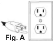
Grounded Tools (Three-Prong Plugs)
Tools marked “Grounding Required” have a three wire cord and three prong grounding plug. The plug must be connected to a properly grounded outlet (See Figure A). If the tool should electrically malfunction or break down, grounding provides a low resistance path to carry electricity away from the user, reducing the risk of electric shock.
The grounding prong in the plug is connected through the green wire inside the cord to the grounding system in the tool. The green wire in the cord must be the only wire connected to the tool's grounding system and must never be attached to an electrically "live" terminal.
Your tool must be plugged into an appropriate outlet, properly installed and grounded in accordance with all codes and ordinances. The plug and outlet should look like those in Figure A.
Double Insulated Tools (Two-Prong Plugs)
Tools marked "Double Insulated" do not require grounding. They have a special double insulation system which satisfies OSHA requirements and
complies with the applicable standards of Underwriters Laboratories, Inc., the Canadian Standard Association and the National Electrical Code. Double Insulated tools may be used in either of the 120 volt outlets shown in FiguresFig. B and C.
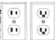
Fig. C
SYMBOLOGY

Insulated

Alternating Current

n_0 XXXX min ^-1 No Load Revolutions per Minute (RPM)

UL Listing for Canada and U.S.

Approval Mark for Mexico
SPECIFICATIONS
Cat. No....0100-20
Volts 120 AC
Amps 7
No Load RPM 0 - 2500
Cat. No....0101-20
Volts 120 AC
Amps 7
No Load RPM 0 - 4300
Cat. No....0200-20
Volts 120 AC
Amps 7
No Load RPM 0 - 1200
Cat. No....0201-20
Volts 120 AC
Amps 7
No Load RPM 0 - 2500
Cat. No....0202-20
Volts 120 AC
Amps 7
No Load RPM 0 - 1200
Cat. No....0299-20
Volts 120 AC
Amps 8
No Load RPM 0 - 850
Cat. No....0300-20
Volts 120 AC
Amps 8
No Load RPM 0 - 850
Cat. No....0302-20
Volts 120 AC
Amps 8
No Load RPM 0 - 850
FUNCTIONAL DESCRIPTION
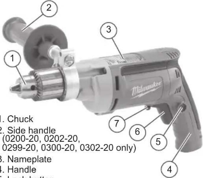
text_image
1. Chuck 2. Side handle (0200-20, 0202-20, 0299-20, 0300-20, 0302-20 only) 3. Nameplate 4. Handle Lock button 7 6 5 3 Milwaukee-
Chuck
-
Side handle
(0200-20, 0202-20,
⚠ WARNING To reduce the risk of injury, always unplug tool before changing or removing accessories. Only use accessories specifically recommended for this tool. Others may be hazardous.
Removing and Replacing Quik-Lok® Cords (Cat. No. 0100-20, 0101-20, 0202-20, 0302-20)
MILWAUKEE's exclusive Quik-Lok® Cords provide instant field replacement or substitution.
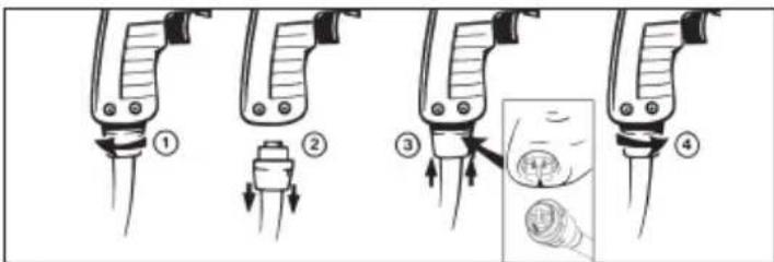
text_image
Diagram illustrating four steps of a medical or laboratory procedure with labeled arrows and a magnified inset showing a magnified circular object.-
To remove the Quik-Lok® Cord, turn the cord nut 1/4 turn to the left and pull it out.
-
To replace the Quik-Lo® Cord, align the connector keyways and push the connector in as far as it will go. Turn the cord nut 1/4 turn to the right to lock.
AWARNING To reduce the risk of injury, always use a side handle when using this tool. Always brace and hold securely.
Adjusting the Side Handle (Cat. No. 0200-20, 0202-20, 0299-20, 0300-20, 0302-20)
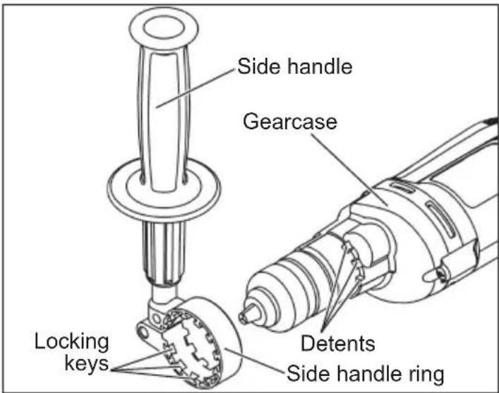
text_image
Side handle Gearcase Locking keys Detents Side handle ring-
Turn the side handle counterclockwise to loosen.
-
Slide the side handle assembly forward over the chuck and rotate to the desired angle.
-
Slide the side handle back to the gearcase and position the locking keys into the detents. The locking keys help prevent the handle from slipping.
NOTE: The side handle ring must clear the chuck.
- Turn the side handle clockwise to tighten.
NOTE: Always use the side handle for best control.
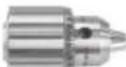
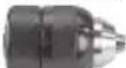
Chuck Identification
| Chuck Type Drill Cat. No. | |||
 | Keyed 0100-20 | 0101-200200-20 | |
 | Double sleeve Keyless | 0201-20 | |
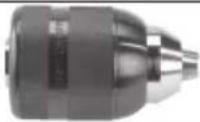 | Single sleeve Keyless | 0202-200302-20 | |
Installing and Removing Bits
AWARNING To reduce the risk of injury, always remove the chuck key from the chuck after each use.
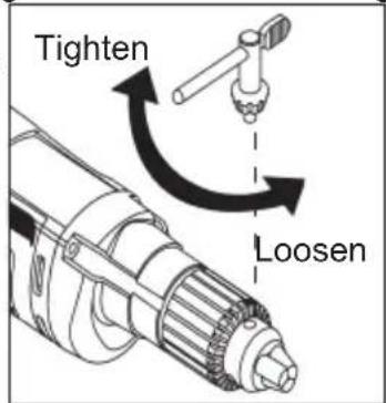
Keyed Chuck
These tools are equipped with a chuck tightened using a key. Always unplug the tool before installing or removing bits.
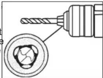
- To open the chuck jaws, place the chuck key in one (1) of the three (3) holes located on the chuck. Turn the key counterclockwise. Be sure the bit shank and chuck jaws are clean. Dirt particles may prevent the bit from lining up properly.
text_image
Tighten Loosen- When using drill bits, insert the bit into the chuck. Center the bit in the chuck jaws and lift it about 1/16" off of the bottom. Tighten the chuck jaws by hand to align the bit. When using screwdriver bits, insert the bit far enough for the chuck jaws to grip the bit shank. Tighten the chuck jaws by hand to align the bit.
- To close the chuck jaws, place the chuck key in each of the three holes in the chuck. Turn the chuck key clockwise. Tighten securely.
- To remove the bit, insert the chuck key into one of the holes in the chuck. Turn the chuck key counterclockwise. Be sure the bit shank and chuck jaws are clean. Dirt particles may prevent the bit from lining up properly.
⚠ WARNING To reduce the risk of injury, do not grasp the bit while the chuck is rotating or while the bit is falling from the chuck.
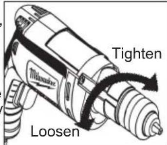
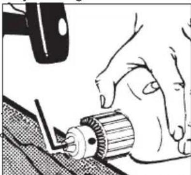
Double Sleeve Keyless Chuck
These tools are equipped with a hand tightening key-less chuck. Always unplug the tool before installing or removing bits.
- To open the chuck jaws, hold the collar and turn the sleeve counterclockwise. Be sure the bit shank and chuck jaws are clean. Dirt particles may prevent the bit from lining up properly.
text_image
Tighten Loosen- When using drill bits insert the bit into the chuck. Center the bit in the chuck jaws and lift it about 1/16" off of the bottom. Tighten the chuck jaws by hand to align the bit.
natural_image
Technical illustration of a drill bit with a magnified inset showing internal components (no text or symbols)When using screwdriver bits, insert the bit far enough for the chuck jaws to grip the bit shank. Tighten the chuck jaws by hand to align the bit.
- To close the chuck jaws, hold the collar and turn the sleeve clockwise. Tighten securely.
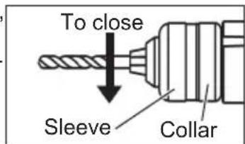
text_image
To close Sleeve Collar- To remove the bit, hold the chuck collar and turn the sleeve counterclockwise to release the bit fr

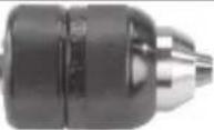
Single Sleeve Keyless Chuck
These tools are equipped with a spindle-lock mechanism and a single-sleeve keyless chuck. Always unplug the tool before inserting or removing bits.
-
To open the chuck jaws, turn the chuck sleeve counterclockwise. Be sure the bit shank and chuck jaws are clean. Dirt particles may prevent the bit from lining up properly.
-
When using drill bits insert the bit into the chuck. Center the bit in the chuck jaws and lift it about 1/16" off of the bottom. Tighten the chuck jaws by hand to align the bit.
When using screwdriver bits, insert the bit far enough for the chuck jaws to grip the bit shan by hand to align the bit.
- To close the chuck jaws, turn the chuck sleeve clockwise. Tighten securely. Several detents will be felt as the chuck sleeve is turned.
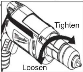
text_image
Tighten MILMAKE Loosen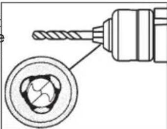
natural_image
Technical illustration of a drill bit with a magnified inset showing internal components (no text or symbols)k. Tighten the chuck jaws

text_image
To close SleeveNOTE: If the spindle rotates when opening or closing the chuck jaws, grasp the chuck and slightly rotate back and forth to engage the spindle-lock mechanism.
The spindle will remain locked until the tool is turned on. The spindle-lock mechanism will automatically disengage when the tool is turned on.
- To remove the bit, turn the chuck sleeve counterclockwise to release the bit from the chuck jaws.
WARNING
To reduce the risk of injury, always wear eye protection.
Chuck Removal
This tool is equipped with a threaded spindle to hold the chuck. Before removing the chuck, unplug the tool and open the chuck jaws. A left-handed thread screw is located inside the chuck to prevent the chuck from loosening when the tool is operated in reverse direction. Remove the screw by turning it clockwise. To
remove the chuck, hold the tool so that only the side of the chuck rests firmly and squarely on a solid workbench. Insert the chuck key or a chuck remover bar in one of the keyholes Turn the chuck so the key is at about a 30 angle to the bench top and strike the key sharply with a hammer so the chuck turns in a counterclockwise direction (looking from the front of the tool). This should loosen the chuck from the spindle which has a right hand thread making it easy to remove the chuck by hand.
natural_image
Illustration of hands operating a mechanical tool with a gear (no text or symbols visible)NOTE: When replacing the chuck, always replace the left hand thread screw in the chuck.
OPERATION
WARNING
To reduce the risk of injury, always wear safety goggles or glasses
with side shields.
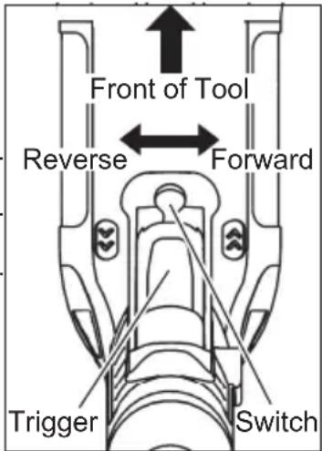
Using Forward/Reverse Switch
-
For forward (clockwise) rotation, push the forward/reverse switch to the left position as shown.
-
For reverse (counterclockwise) rotation, push the forward/reverse switch to the right position as shown. Although an interlock prevents reversing the tool while the motor is running, allow it to come to a full stop before reversing.
text_image
Front of Tool Reverse Forward Trigger SwitchAWARNING To reduce the risk of injury, keep hands and cord away from the bit and all moving parts.
Starting, Stopping and Controlling Speed
- To start the tool, pull the trigger.
- To stop the tool, release the trigger.
- To vary the drilling speed, simply increase or decrease pressure on the trigger. The further the trigger is pulled, the greater the speed.
Locking Trigger
The lock button holds the trigger in the ON position for continuous full speed use.
- To lock the trigger, hold the lock button in while pulling the trigger. Release the trigger.
- To unlock the trigger, pull the trigger and release. The lock button will pop out.
APPLICATIONS
| Wood Wood/Steel Steel | ||||||||
| Cat. No. | No Load RPM | Flat Boring Bits | Auger Bits | Hole Saws | Self-feed Bits | Pathfinder^TM Bits | Twist Bits | Hole Saws |
| 0100-20 | 0 - 2500 | 1-1/2" | NR | NR | NR | NR | 1/4" | NR |
| 0101-20 | 0 - 4300 | 1-1/4" | NR | NR | NR | NR | 1/4" | NR |
| 0200-20 | 0 - 1200 | 1-1/2" | 1" | 3-1/4" | NR | 1-1/4" | 1/2" | 1-5/8" |
| 0201-20 | 0 - 2500 | 1-1/2" | 7/8" | 2-1/4" | NR | 1-1/4" | 1/2" | NR |
| 0202-20 | 0 - 1200 | 1-1/2" | 1" | 3-1/4" | NR | 1-1/4" | 1/2" | 1-5/8" |
| 0299-20 | 0 - 850 | 1-1/2" | 1-1/2" | 3-5/8" | 2-9/16" | 1-1/4" | 3/4" | 2" |
| 0300-20 | 0 - 850 | 1-1/2" | 1-1/2" | 3-5/8" | 2-9/16" | 1-1/4" | 3/4" | 2" |
| 0302-20 | 0 - 850 | 1-1/2" | 1-1/2" | 3-5/8" | 2-9/16" | 1-1/4" | 3/4" | 2" |
NR = Not recommended
WARNING To reduce the risk of explosion, electric shock and property damage, always check the work area for hidden pipes and wires before drilling.
Selecting Bits
When selecting a bit, use the right type for your job. For best performance, always use sharp bits.
Drilling
- Before drilling, be sure the workpiece is clamped securely. Use backing material to prevent damage to the workpiece during breakthrough.
- When starting a hole, place the drill bit on the work surface and apply firm pressure. Begin drilling at a slow speed, gradually increasing the speed as you drill.
- Always apply pressure in line with the bit. Use enough pressure to keep the drill biting, but do not push hard enough to stall the motor.
- Reduce pressure and ease the bit through the last part of the hole. While the tool is still running, pull the bit out of the hole to prevent jamming.
Drilling in Wood, Composition Materials and Plastic
When drilling in wood, composition materials and plastic, start the drill slowly, gradually increasing speed as you drill. When using twist drill bits, pull the bit out of the hole frequently to clear chips from the bit flutes. Use low speeds for plastics with a low melting point.
Drilling in Masonry
When drilling in masonry, use high speed carbide-tipped bits. Drilling soft masonry materials such as cinder block requires little pressure. Hard materials like concrete require more pressure. A smooth, even flow of dust indicates the proper drilling rate. Do not let the bit spin in the hole without cutting. Do not use water to settle dust or to cool bit. Both actions will damage the carbide.
Drilling in Metal
When drilling in metal, use high speed steel twist drills or hole saws. Use slow speeds for hard metals and high speeds for softer metals. Lubricate drill bits with cutting oil when drilling in iron or steel. Use a coolant when drilling in nonferrous metals such as copper, brass or aluminum. Back the material to prevent binding and distortion on breakthrough.
Driving Screws
When driving screws, use the proper screwdriver bit for your job. After drilling pilot and shank holes, start the screw slowly and increase the speed as driving progresses. Set the screw by slowing to a stop. Do not run screws down at excessive speeds. To remove screws, reverse the motor.
Stalling
If the tool seems as if it is about to stall, maintain a firm grip and reduce pressure slightly to allow the bit to regain speed. If the tool does stall, releas the trigger immediately. Reverse the motor, remove the bit from the work and start again. Do not pull the trigger on and off in an attempt to start a stalled drill. This can damage the drill.
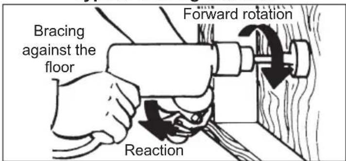
WARNING High rotational force. To reduce the risk of injury, always hold or brace securely. Always use side handle on tools rated 1200 rpm or less.
Bit Binding
A high rotational force occurs when a bit binds. If the bit binds, the tool will be forced in the opposite direction of the bit rotation. Bits may bind if they are misaligned or when they are breaking through a hole. Wood boring bits can also bind if they run into nails or knots. Be prepared for bit binding situations. To reduce the chance of bit binding:
- Use sharp bits. Sharp bits are less likely to bind when drilling.
- Use the proper bit for the job. There are bits that are designed for specific purposes.
- Use caution when drilling pitchy, knotty, wet or warped material or when drilling in material that may contain nails.
Typical Bracing Methods
text_image
Bracing against the floor Forward rotation Reaction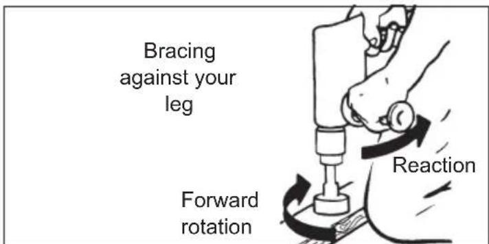
text_image
Bracing against your leg Forward rotation Reaction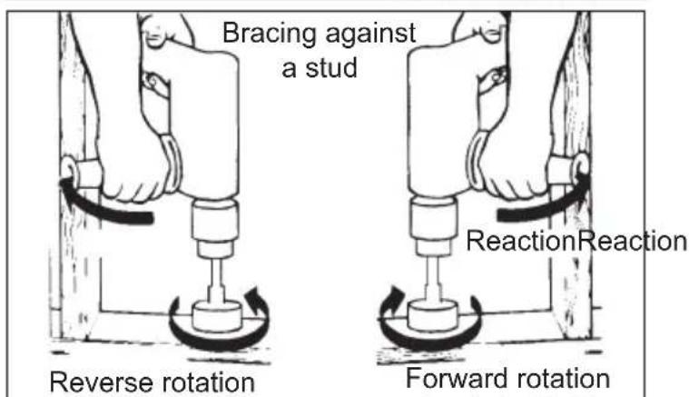
text_image
Bracing against a stud Reverse rotation ReactionReaction Forward rotationMAINTENANCE
AWARNING To reduce the risk of injury, always unplug the tool before performing any maintenance. Never disassemble the tool. Contact a MILWAUKEE service facility for ALL repairs.
Maintaining Tools
Keep your tool in good repair by adopting a regular maintenance program. Inspect your tool for issues such as undue noise, misalignment or binding of moving parts, breakage of parts, or any other condition that may affect the tool operation. Return the tool to a MILWAUKEE service facility for repair. After six months to one year, depending on use, return the tool to a MILWAUKEE service facility for inspection.
⚠ WARNING To reduce the risk of personal injury, electric shock and damage, never immerse your tool in liquid or allow a liquid to flow inside it.
Cleaning
Clean dust and debris from vents. Keep handles clean, dry and free of oil or grease. Use only mild soap and a damp cloth to clean, since certain cleaning agents and solvents are harmful to plastics and other insulated parts. Some of these include gasoline, turpentine, lacquer thinner, paint thinner, chlorinated cleaning solvents, ammonia and household detergents containing ammonia. Never use flammable or combustible solvents around tools.
Repairs
For repairs, return the tool to the nearest service center.
ACCESSORIES
⚠ WARNING Use only recommended accessories. Others may be hazardous.
For a complete listing of accessories, go online to www.milwaukeetool.com or contact a distributor.
SERVICE - UNITED STATES
1-800-SAWDUST (1.800.729.3878)
Monday-Friday, 7:00 AM - 6:30 PM CST
or visit www.milwaukeeetool.com
Contact Corporate After Sales Service Technical Support with technical, service/repair, or warranty questions.
Email: metproductsupport@milwaukeeetool.com
Register your tool at www.milwaukeetool.com...
• to receive important notifications regarding your purchase
• to ensure that your tool is protected under the warranty
• to become a Heavy Duty club member
SERVICE - CANADA
Milwaukee Tool (Canada) Ltd 1.800.268.4015
Monday-Friday, 7:00 AM - 4:30 PM CST
or visit www.milwaukeetool.ca
LIMITED WARRANTY USA & CANADA
Every MILWAUKEE power tool (including cordless product – tool, battery pack(s) - see separate & distinct CORDLESS BATTERY PACK LIMITED WARRANTY statements & battery charger and Work Lights*) is warranted to the original purchaser only to be free from defects in material and workmanship. Subject to certain exceptions, MILWAUKEE will repair or replace any part on an electric power tool which, after examination, is determined by MILWAUKEE to be defective in material or workmanship for a period of five (5) years* after the date of purchase unless otherwise noted. Return of the power tool to a MILWAUKEE factory Service Center location or MILWAUKEE Authorized Service Station, freight prepaid and insured, is required. A copy of the proof of purchase should be included with the return product. This warranty does not apply to damage that MILWAUKEE determines to be from repairs made or attempted by anyone other than MILWAUKEE authorized personnel, misuse, alterations, abuse, normal wear and tear, lack of maintenance, or accidents. *The warranty period for, Job Site Radios, M12™ Power Port, M18™ Power Source, Jobsite Fan and Trade Titan™ Industrial Work Carts is one (1) year from the date of purchase. The warranty period for a LED Work Light and LED Upgrade Bulb is a limited LIFETIME warranty to the original purchaser only, if during normal use the LED bulb fails the Work Light or Upgrade Bulb will be replaced free of charge. *This warranty does not cover Air Nailers & Stapler, Airless Paint Sprayer, Cordless Battery Packs, Gasoline Driven Portable Power Generators, Hand Tools, Hoist – Electric, Lever & Hand Chain, M12™ Heated Jackets, Reconditioned product and Test & Measurement products. There are separate and distinct warranties available for these products.
Warranty Registration is not necessary to obtain the applicable warranty on a MILWAUKEE power tool product. The manufacturing date of the product will be used to determine the warranty period if no proof of purchase is provided at the time warranty service is requested. ACCEPTANCE OF THE EXCLUSIVE REPAIR AND REPLACEMENT REMEDIES DESCRIBED HEREIN IS A CONDITION OF THE CONTRACT FOR THE PURCHASE OF EVERY MILWAUKEE PRODUCT. IF YOU DO NOT AGREE TO THIS CONDITION, YOU SHOULD NOT PURCHASE THE PRODUCT. IN NO EVENT SHALL MILWAUKEE BE LIABLE FOR ANY INCIDENTAL, SPECIAL, CONSEQUENTIAL OR PUNITIVE DAMAGES, OR FOR ANY COSTS, ATTORNEY FEES, EXPENSES, LOSSES OR DELAYS ALLEGED TO BE AS A CONSEQUENCE OF ANY DAMAGE TO, FAILURE OF, OR DEFECT IN ANY PRODUCT INCLUDING, BUT NOT LIMITED TO, ANY CLAIMS FOR LOSS OF PROFITS. SOME STATES DO NOT ALLOW THE EXCLUSION OR LIMITATION OF INCIDENTAL OR CONSEQUENTIAL DAMAGES, SO THE ABOVE LIMITATION OR EXCLUSION MAY NOT APPLY TO YOU. THIS WARRANTY IS EXCLUSIVE AND IN LIEU OF ALL OTHER EXPRESS WARRANTIES, WRITTEN OR ORAL. TO THE EXTENT PERMITTED BY LAW, MILWAUKEE DISCLAIMS ANY IMPLIED WARRANTIES, INCLUDING WITHOUT LIMITATION ANY IMPLIED WARRANTY OF MERCHANTABILITY OR FITNESS FOR A PARTICULAR USE OR PURPOSE; TO THE EXTENT SUCH DISCLAIMER IS NOT PERMITTED BY LAW, SUCH IMPLIED WARRANTIES ARE LIMITED TO THE DURATION OF THE APPLICABLE EXPRESS WARRANTY AS DESCRIBED ABOVE. SOME STATES DO NOT ALLOW LIMITATIONS ON HOW LONG AN IMPLIED WARRANTY LASTS, SO THE ABOVE LIMITATION MAY NOT APPLY TO YOU, THIS WARRANTY GIVES YOU SPECIFIC LEGAL RIGHTS, AND YOU MAY ALSO HAVE OTHER RIGHTS WHICH VARY FROM STATE TO STATE.
This warranty applies to product sold in the U.S.A. and Canada only. Please consult the 'Service Center Search' in the Parts & Service section of MILWAUKEE's website www.milwaukeeetool.com or call 1.800.SAWDUST (1.800.729.3878) to locate your nearest service facility for warranty and non-warranty service on a Milwaukee electric power tool.
LIMITED WARRANTY - MEXICO, CENTRAL AMERICA & CARIBBEÁN
TECHTRONIC INDUSTRIES' warranty is for 5 year since the original purchase date.
This warranty card covers any defect in material and workmanship on this Power Tool.
To make this warranty valid, present this warranty card, sealed/ stamped by the distributor or store where you purchased the product, to the Authorized Service Center (ASC). Or, if this card has not been sealed/stamped, present the original proof of purchase to the ASC. Call toll-free 1 800 832 1949 to find the nearest ASC, for service, parts, accessories or components.
Procedure to make this warranty valid
Take the product to the ASC, along with the warranty card sealed/ stamped by the distributor or store where you purchased the product, and there any faulty piece or component will be replaced without cost for you. We will cover all freight costs relative with this warranty process.
Exceptions
This warranty is not valid in the following situations:
a) When the product is used in a different manners from the end-user guide or instruction manual.
b) When the conditions of use are not normal.
c) When the product was modified or repaired by people not authorized by TECHTRONIC INDUSTRIES.
Note: If cord set is damaged, it should be replaced by an Authorized Service Center to avoid electric risks.
SERVICE AND ATTENTION CENTER:
Av Presidente Mazarik 29 Piso 7, 11570 Chapultepec Morales
Miguel Hidalgo, Distrito Federal, Mexico
Ph. 52 55 4160-3547
IMPORTED AND COMMERCIALIZED BY:
TECHTRONIC INDUSTRIES MEXICO, S.A. DE C.V.
Av Presidente Mazarik 29 Piso 7, 11570 Chapultepec Morales
Miguel Hidalgo, Distrito Federal, Mexico
Model:
Date of Purchase:
Distributor or Store Stamp:
RÈGLES DE SÉCURITÉ GÉNÉRALES RELATIVES AUX OUTILS ELECTRIQUES
AVERTISSEMENT
text_image
Diagram illustrating four steps of a medical or laboratory procedure with labeled components and directional arrowsnatural_image
Technical illustration of a drill bit with a magnified inset showing internal components (no text or symbols)natural_image
Diagram of a drill bit with a magnified inset showing internal components (no text or symbols)natural_image
Illustration of hands operating a mechanical tool with a gear-like component (no text or symbols visible)NR = non recommendable
Milwaukee Tool (Canada) Ltd 1.800.268.4015
Monday-Friday, 7:00 AM - 4:30 PM CST
www.milwaukeetool.ca
GARANTIE LIMITÉE -
AUX ÉTATS-UNIS ET AU CANADA
text_image
Diagram illustrating four steps of a medical or laboratory procedure involving pipette manipulation and tool insertion, with numbered instructions and magnified detail.natural_image
Technical illustration of a drill bit with a magnified inset showing internal components (no text or symbols)natural_image
Diagram of a drill bit with a magnified inset showing internal components (no text or symbols)natural_image
Illustration of hands operating a mechanical tool with a gear-like component (no text or symbols visible)Lunes a Viernes (9am a 6pm)