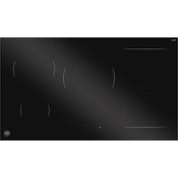
P905I1M30NP - Cooker BERTAZZONI - Free user manual and instructions
Find the device manual for free P905I1M30NP BERTAZZONI in PDF.


User questions about P905I1M30NP BERTAZZONI
0 question about this device. Answer the ones you know or ask your own.
Ask a new question about this device
Download the instructions for your Cooker in PDF format for free! Find your manual P905I1M30NP - BERTAZZONI and take your electronic device back in hand. On this page are published all the documents necessary for the use of your device. P905I1M30NP by BERTAZZONI.
USER MANUAL P905I1M30NP BERTAZZONI
text_image
BERTAZZO ITALIA| IT | MANUALE D'INSTALLAZIONEMANUALE D'USO E MANUTENZIONEPIANO COTTURA A INDUZIONE | 3 |
| EN | INSTALLATION MANUALUSER AND MAINTENANCE MANUALINDUCTION HOB | 37 |
| FR | MANUEL D'INSTALLATIONMANUEL D'UTILISATION ET D'ENTRETIENTABLE DE CUISSON À INDUCTION | 69 |
| NL | INSTALLATIEHANDLEIDINGGEBRUIKS- EN ONDERHOUDSHANDLEIDINGINDUCTIEKOOKPLAAT | 101 |
DALLA SCRIVANIA DEL PRESIDENTE
Gentile Cliente,
text_image
1 2 Bertazzoni Spa Via Palazzina, 8 42016 Guastalla (RE) Italy www.bertazzoni.com UK CA CE PXXXXXXXXXX Produc I Type : Inducio n Built-i n Hob Factor y Model: PXXXXXXXXXXX Rated Voltage : 220-24.0 V~ Rated Frequency : 50/6.0 Hz Total Power r (kw) : 7.0 kw (230v~) : CLASS I Made in China SN:XXX X 0000 1 3 ATTENTION: This appliance must be installed in accordance with it currently in force and must be only used in well ventilated premises instructions before installing or using this appliance. regulations Read the 8 05 797 1 10 50 694Fig. 1
natural_image
Cross-sectional technical diagram of a mechanical assembly with hatched areas and a central curved line (no text or symbols)Fig. 5

NOTA
text_image
88 88 88 8 8 GRILL CLEAN F PFig. 9
ICONA DESCRIZIONE
text_image
Diagram showing two hand positions with check and cross marks, likely illustrating correct and incorrect states of a rule or procedure.Fig. 10
text_image
Diagram showing cooking process steps with checkmark and cross symbols indicating correct and incorrect statesFig. 11
text_image
Diagram showing cooking process with cooking pot and three identical diagrams of a container being heated, marked with red X and green checkmark.Fig. 12
text_image
Diagram comparing cooking methods: one with upward arrow and checkmark, the other with left-pointing arrows and a red X mark.Fig. 13
text_image
Diagram illustrating a screwdriver tool interacting with a mechanical device, showing a black curved arrow indicating motion direction.Fig. 14
Collegamento bifase 4x4 คิจ20-240 / 380- 415V 2N\~
flowchart
graph TD
    A["Component 1"] --> B["L1"]
    C["Component 2"] --> D["L2"]
    E["Component 3"] --> F["N"]
    G["Component 4"] --> H["Ground Symbol"]
    I["Component 5"] --> J["Ground Symbol"]
Fig. 15
Dear new owner of a Bertazzoni appliance,
I want to thank you for choosing one of our beautiful products for your home.
My family started manufacturing kitchen appliances in Italy in 1882, building a reputation for quality of engineering and passion for good food.
Today, our products stand out because of their unique blend of authentic Italian design and superior appliance technology. It is our mission to make products that function perfectly and bring joy to their owners.
By making beautiful products we respond to our customers' flair for good design. By making them versatile and easy-to-use, cooking with Bertazzoni becomes a real pleasure.
This manual will help you learn to use and care for your Bertazzoni appliance in the safest and most effective way, so that it can give you the highest satisfaction for years to come.
Enjoy!
Paolo Bertazzoni
President
text_image
Pedro SectorzomMANUAL VALIDITY
The following manual applies to all the product codes listed below:
P905I1M30GP
P905I1M30XP
P905I1M30CP
P905I1M30NP
GENERAL INFORMATION 41
READING THE MANUAL 41
INTRODUCTION AND SAFETY 41
APPLIANCE IDENTIFICATION 42
GENERAL SAFETY INFORMATION 42
IMPORTANT NOTES 44
MANUFACTURER LIABILITY 44
ENVIRONMENTAL PROTECTION 44
INSTALLATION 45
IMPORTANT NOTES 45
WARNINGS FOR USE 45
INSERTING THE HOB 46
INSTALLATION OVER A BUILT-IN OVEN 48
INSTALLATION OVER A COMPARTMENT OR DRAWERS 48
FLUSH-MOUNTED INSTALLATION 49
FIXING THE HOB 49
ROOM VENTILATION 50
ELECTRICAL CONNECTION 50
POSSIBLE CONNECTIONS WITH THE CABLE SUPPLIED 51
USE 52
GENERAL SAFETY INSTRUCTIONS 52
HOB DESCRIPTION 53
COOKING WITH INDUCTION 53
SWITCHING ON AND OFF 55
CLEANING THE APPLIANCE 64
THINGS TO AVOID 64
CLEANING THE DECORATIVE FRAMES 64
CLEANING THE GLASS 64
TROUBLESHOOTING 65
WARRANTY 67
WARRANTY AND SERVICE 67
ASSISTENZA 68
CUSTOMER SERVICE 68
READING THE MANUAL
INTRODUCTION AND SAFETY
These instructions are suitable for different types of Read the instructions provided in this manual carefully appliances, so they may contain descriptions of functions before installing and/or using the appliance.
which your appliance may not contain or support.
This will help you to get to know your new device.
The images and illustrations in this document refer to
various models and may differ slightly from the product. Keep this document to hand so that you consult it at a purchase. moment, and hand it on to any subsequent owners.
The manufacturer does not accept any responsibility for
personal injury or damage to property arising from incorrect installation or misuse of the appliance. This manual and give due consideration to the safety no such as: "Attention", "Warning" and "Danger" which appeal in the text
Read the safety messages provided in the introduction to this manual and give due consideration to the safety no effect such as: "Attention", "Warning" and "Danger" which appears in the text.
The manufacturer reserves the right to modify the various models as required to comply with the technical regulation in force.
In the event of complaints, please contact the customer service.

DANGER
This symbol indicates a situation that is a danger to you and others. Read it carefully and make sure that you have perfectly understood the causes of potential dangerous or fatal accidents.

WARNING
This symbol indicates safety information. Read it carefully and make sure that you have perfectly understood the causes of potential dangerous accidents.

CAUTION
This symbol indicates a procedure which could put the appliance's structure or components at risk. Take particular care over these procedures.

NOTE
This symbol indicates useful advice and draws your attention to correct procedures and practices. Complying with the instructions marked with this symbol will avoid problems for you.
The symbol highlights methods or procedures for correct use of the appliance.
APPLIANCE IDENTIFICATION
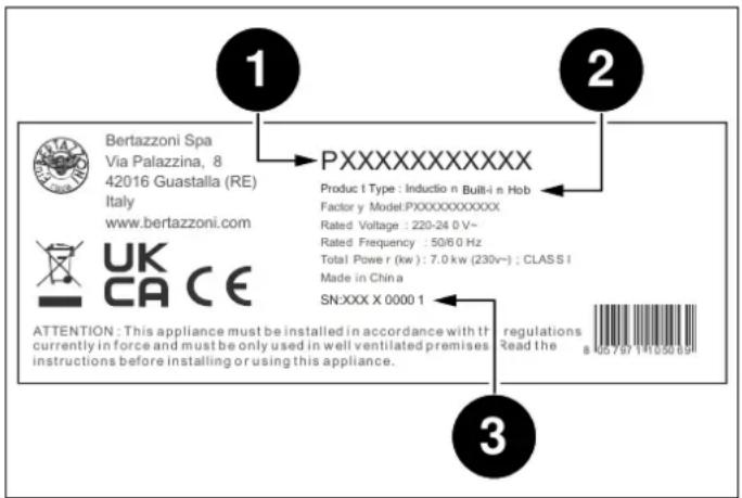
text_image
1 2 Bertazzoni Spa Via Palazzina, 8 42016 Guastalla (RE) Italy www.bertazzoni.com UK CA CE PXXXXXXXXXX Produc I Type : Inducio n Built-i n Hob Factor y Model:XXXXXXX Rated Voltage : 220-24 0 V~ Rated Frequency : 50/6 0 Hz Total Power (kw) : 7.0 kw (230v~) : CLASS I Made in China SN:XXX X 0000 1 3 ATTENTION: This appliance must be installed in accordance with it currently in force and must be only used in well ventilated premises instructions before installing or using this appliance. regulations Read the 8 05 797 1 1050 694Fig. 1
The data plate contains the following information:
1) Sales code
2) Model
3) Serial number
GENERAL SAFETY INFORMATION
This appliance complies with European directive 2012/19/EU (RoHS).
This appliance is tagged in accordance with European directive 2012/19/EC regarding waste electrical and electronic equipment (WEEE).
This directive contains the regulations governing the collection and recycling of decommissioned appliances throughout the European Union.
The symbol of a waste bin with a cross over it which appears on the product indicates that Waste Electrical and Electronic Equipment (WEEE) must not be thrown away with ordinary urban waste but must be disposed of separately, so it can undergo special processing to enable its reuse or specific treatment for safe removal and disposal of any substances harmful to the environment and extraction of raw materials which can be recycled.
Therefore, WEEE must be delivered to Recycling Centres run by Municipal Authorities or Waste Management Companies. What's more, when a new appliance is purchased WEEE can be consigned to the retailer, who is obliged to take it back free of charge ("1:1" take-back). "Very small" WEEE (with no dimension exceeding 25 cm) can be consigned to retailers free of charge even when no purchase is made ("0:1" take-back - which however is only compulsory for stores with sales area of over 400 m2).

DANGER
This appliance is not intended for use by people, including children, with reduced mental or motor capabilities, or who do not have experience in or knowledge of the product's operation. These persons may only use the appliance under the supervision of a person responsible for their safety and with suitable instruction in use of the appliance.

DANGER
If the surface of the induction hob is cracked, switch the appliance off to avoid the risk of electric shocks.

DANGER
Fire hazard: do not leave inflammable objects on cooking surfaces.

DANGER
Automatic cooking on the hob with fat or oil may be hazardous and may cause fires. If a fire breaks out, do not attempt to put it out with water. Switch the appliance off and cover the flames with a lid or a fire blanket.

DANGER
This appliance can be used by children over 8 years of age and persons with reduced physical, sensory or mental capabilities, or without the necessary of experience and knowledge, provided they are supervised or have received instruction concerning safe use of the appliance and an understanding of the hazards involved. Children must not play with the appliance. Cleaning and user maintenance must not be carried out by unsupervised children.

WARNING
Accessible parts may become hot during use. Children must be kept well away.

WARNING
The appliance must not be installed on a stand.

WARNING
Do not use steam cleaners to clean the appliance.

CAUTION
Do not use an external timer or other remote control systems to operate the appliance.
READ THESE INSTRUCTIONS CAREFULLY BEFORE INSTALLING AND USING THE APPLIANCE.
ENVIRONMENTAL PROTECTION
Please think of the environment when disposing of the packaging.
These instructions are valid only for the countries with identifying symbols are included on the cover of this manual and on the appliance label.
The manufacturer shall not be held liable for property damage or personal injury resulting from incorrect installation or improper use of the appliance.

This appliance is tagged in accordance with European directive 2012/19/EU regarding waste electrical and electronic equipment (WEEE).
This directive contains the regulations governing the collection and recycling of decommissioned appliances throughout the European Union.
The manufacturer shall also not be held liable for any imprecisions due to printing or transcription errors in this booklet.
The appearance of the figures included herein is only guidance.
The manufacturer reserves the right to make modifications to its products when it considers this necessary or beneficial; however the essential safety and performance characteristics shall not be affected.
THIS APPLIANCE IS DESIGNED FOR NON-PROFESSIONAL, DOMESTIC USE.
This user manual is an integral part of the appliance and must therefore be kept in its entirety in a place accessible to the user for the entire lifetime of the appliance.
Read this manual before using the appliance.
MANUFACTURER LIABILITY
The packaging of this appliance is composed of the elements strictly necessary to ensure sufficient protection during transport. The packaging materials are completely recyclable, thus reducing their environmental impact. Please help to protect the environment by taking the following tips into consideration:
- Sort the packaging materials for recycling.
- Render the old appliance unusable before taking it to collection facility. Ask the competent local authorities for details of the nearest recycling center you can take the
and old appliance to.
Do not dispose of used oil down the drain. Keep it in a closed container and take it to a recycling center; if this is not possible, dispose of it in mixed waste (in this manner it will be disposed of at a monitored facility although this is not the best solution, it at least prevents contamination of the sewage/water systems).
The manufacturer shall bear no liability for property damage or personal injury due to:
• use of the appliance other than that specified;
- failure to comply with the instructions in the user manual;
- tampering with/unauthorized modifications to any part of the appliance;
• use of non-genuine spare parts;

CAUTION
Applying the € marking on this product is a declaration, under the manufacturer's full responsibility, that the appliance complies with all European health, safety and environmental requirements laid out in the legislation.
The installation, all adjustments, transformations and maintenance listed in this section must only be pe
by qualified technicians (in accordance with applicable legislation). Incorrect installation may cause injury to people and pets or damage to property, for which the manufacturer cannot be held liable. The appliance's automatic regulation or safety devices may only be modified by the manufacturer or a duly authorized su during the appliance's lifetime.
Ensure all necessary PPE is used when carrying out the installation.
IMPORTANT NOTES
The hob can be inserted between kitchen units or between a unit and a masonry wall. The rear wall and surrounding always keep the cooking area and the bottom of the surfaces must be able to withstand temperatures of up to trans dry 90°C. To avoid the plastic laminate covering the unit coming Never use frozen pans
unstuck, the glue that joins them must withstand temperatures of at least 100^ C. Do not place or leave switched off
The top on which the hob is installed must be stable, and horizontal. The worktop into which the appliance is fitted must be able to support loads of approx. 60 kg, case of thin worktops, use a reinforcing material that is resistant to heat and humidity. Check the flatness of the hob only after it has been fitted.
The appliance must be installed in compliance with current regulations.
This device is not connected to combustion gas venting devices. It must therefore be connected in accordance with the above-mentioned installation rules. Special attention must be paid to the instructions regarding the aeration ventilation of rooms.
The distance between the extractor hood and the hob m be at least the distance indicated in the extractor hood's assembly instructions.
If easily flammable materials are installed above the hobg. a shelf), the safety distance F indicated in Fig. 2 m maintained.
WARNINGS FOR USE
Use flat-bottomed pans suitable for induction hobs
Position the pans before switching on the hob
Make sure the pan is centred in relation to the hob
Do not move away when cooking food with oil and f which are highly flammable
To prevent the hob from getting scratched, move the pans by lifting them without sliding them
Pans with scratched or damaged bases can damage 1 ceramic glass
Sand, salt, sugar or other abrasive substances can damage the ceramic glass
Always keep the cooking area and the bottom of the pans dry
Never use frozen pans
Do not place or leave empty pans on the hob, even switched off
Never place a boiling pan on the control panel. The electronics under the glass could be damaged
In the Never use 2 cooking containers at the same time on single hob
Do not heat closed containers (e.g. food jars). Due to overpressure, the containers and/or jars may explode and cause injury
Ceramic glass is very resistant, but not unbreakable. Avoid dropping objects, even small ones, on the cerar glass
Do not hit the edges of the glass with pans
Use maximum power only to boil water or to fry
Do not preheat empty pans. The bottom of the pan quickly reach very high temperatures and damage both the ceramic glass and the inner coating of the pan
Be especially careful not to spill sugar or sweet mixtures on the hob during cooking, and avoid using materials substances that could melt (plastic or aluminium foil).
this case, switch off the hob immediately and clean v a scraper while the cooking zone is still warm. If the ceramic hob zone is not cleaned immediately, residues may form that cannot be removed once the cooking zone has cooled down
The electronic part may cause audible noises during operation. The cooling fan may also be noticeable. The cooling fan can continue to operate even after the cooking process is finished, to cool the electronic components. This does not mean that the induction he is faulty or that it is not working properly
If the hob is installed over a drawer, it is essential to respect the distances indicated in the installation drawings and not to use the drawer to store flammab objects. Any objects in the drawer must be heat resist and remain at least 2cm from the bottom of the wor
- If the hob is installed over a drawer, the hob ventilation you use an adapter for cooking pots that are not heats the items inside the drawer during the cooking induction-compatible, the hob's heating system could be process. Do not store sharp or small objects, paper, damaged.
napkins, etc. in the drawer. These could penetrate or be sucked in through the ventilation slots and damage the cooling fan or affect cooling

CAUTION
The cooking process must be constantly monitored
- If the appliance is built-in over an oven equipped with a pyrolytic cleaning system, it must not be used while the pyrolytic process is in progress, as this could trigger the hob's overheating protection
INSERTING THE HOB
- Warning for people wearing pacemakers: be aware that the facture that the hob is fully present and undamaged after an electromagnetic field is generated in the immediatemoving all loose parts from their inner and outer vicinity of the appliance when it is in operation. The packaging. In the event of any uncertainty, do not use possibility of affecting the functioning of the pacemaker is very remote. If in doubt, contact the manufacturer of the pacemaker or your doctor. Considering the critical dimensions of the appliance (see
- The electromagnetic field of the switched-on hob can influence the functioning of objects subject to magnetisation. Do not keep credit cards, memory devices or calculators in the immediate vicinity of the hob
Considering the critical dimensions of the appliance (see Fig. 2), make an opening in the top of the unit follow measurements in the table.
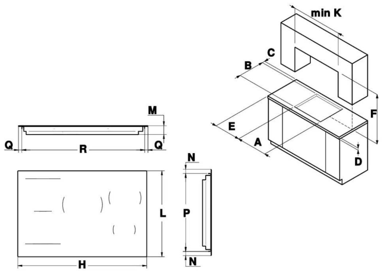
Fig. 2
| A | B | C | DEFK | |||||||||||||
| Hob | 90 | cm | 840 | mm | 475 | mm | 50 | mm | 30 | mm | 100 | mm | 700 | mm | min. | 900 mm |
| Hob Frame | 90 | cm | -840 | mm | 475 | mm | 50 | mm | 30 | mm | 100 | mm | 700 | mm | min. | 900 mm |
| HLMNP | Q | R | |||||||||||||||
| Hob | 90 | cm | 900 | mm | 520 | mm | 49 | mm | 25 | mm | 470 | mm | 32.5 | mm | 835 mm | ||
| Hob Frame | 90 | cm | -940 | mm | 524 | mm | 49 | mm | 27 | mm | 470 | mm | 52.5 | mm | 835mm | ||
INSTALLATION OVER A BUILT-IN OVEN
INSTALLATION OVER A COMPARTMENT OR DRAWERS
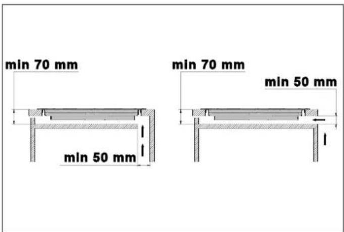
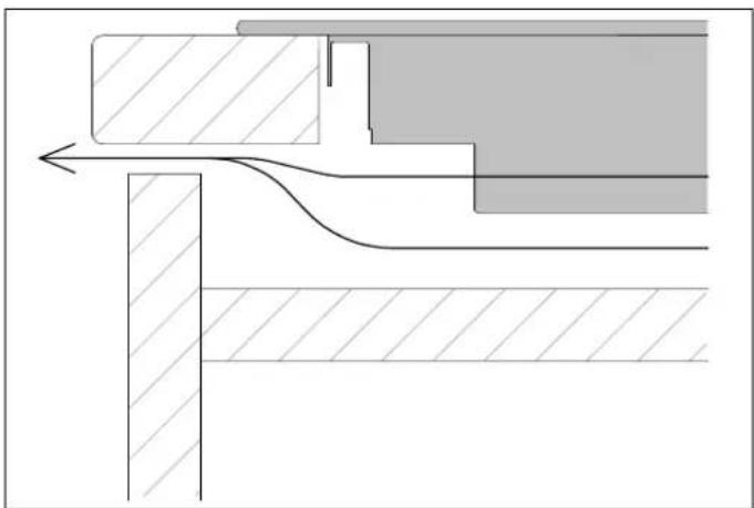
If installed over an oven, space must be left between the
bottom of the hob and the top of the installed product. The clearance between the oven and the kitchen units of allow for ventilation of the entire compartment (see figure) installed appliances must be enough to ensure. The oven must be equipped with a cooling device. The sufficient ventilation and air discharge.
manufacturer shall bear no liability in the event of the hob
being installed in combination with an oven from another manufacturer. The internal width of the unit must be at least equal to internal width of the cut-out in the worktop so that, once The internal width of the unit must be at least equal to internal width of the cut-out in the worktop so that, once embedded, the hob is freely accessible from underneath and the lower casing can be removed for maintenance. the hob is not freely accessible from below after installa the seal on the kitchen worktop must be removed so if the hob can be dismantled (once this has been done, it seal must be put back in place).
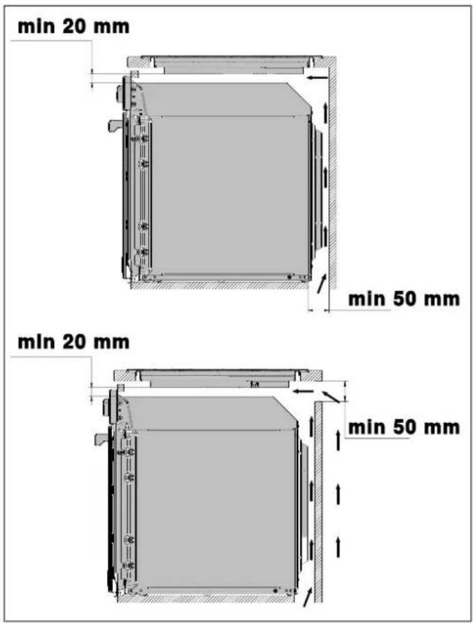
text_image
min 20 mm min 50 mm min 20 mm min 50 mmFig. 3
text_image
min 70 mm min 50 mm min 70 mm min 50 mmFig. 4
natural_image
Cross-sectional technical diagram of a mechanical assembly with hatched areas and layered components (no text or labels)Fig. 5

NOTE
To further optimise the product's performance, a front discharge for the cooling air can be provided in the unit
FLUSH-MOUNTED INSTALLATION
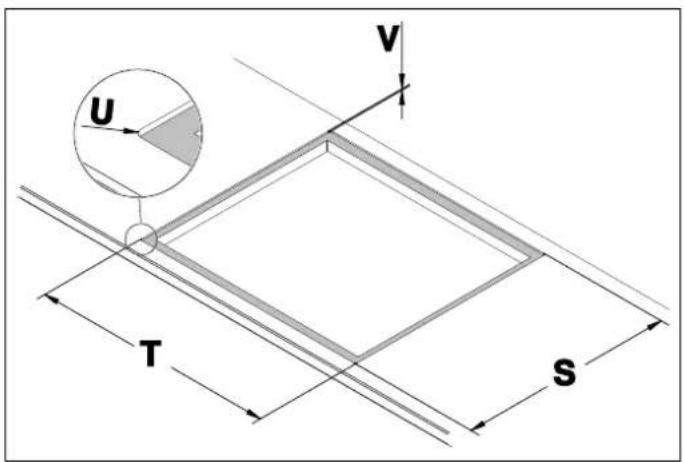
The hob can be flush-mounted only on natural stone (granite, marble), solid wood and tiled worktops. For worktops made of other materials, contact the manufacturer to check whether they are suitable for mounting a hob.
Check the flatness of the hob only after it has been
After installing the hob in the niche, spray heat-resistant silicone sealant (at least 160°C) into the gap between the hob and the worktop.
The recommended height for applying the seal is indicated in the drawing.
text_image
U V T SFig. 6
TSUV
Hob 90 cm 904 mm 524 mm 5 mm 5 mm
FIXING THE HOB
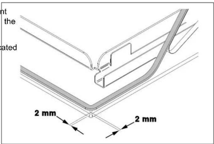
To prevent accidental infiltration of liquid into the unit be the appliance is equipped with a special seal.
1) After cleaning the surface, spread the sealant along the upper edge of the top where the hob is built-in.
2) Glue it 2 mm from the edge of the outer glass or the decorative frame.
text_image
nt the ated 2 mm 2 mmFig. 7
3) Fit the hob into the opening in the unit.

NOTE
The seal must also be inserted for flush-mounted installations.
ROOM VENTILATION
ELECTRICAL CONNECTION
To guarantee that the appliance functions correctly, the The electrical connection must be made in accordance with room where it is installed must be properly ventilated. applicable standards and legislation.
Ventilation of the room must be guaranteed in compliance. Before making the connection, check that:
with current regulations.
- The characteristics of the mains power supply are compatible with the data shown on the label.
- The connection and the system must be earthed in accordance with current regulations.

NOTE
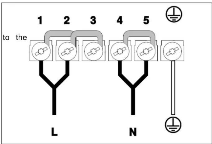
The cable supplied allows for both single-phase and two-phase connection.
Position the power cable in such a way that it does not reach a temperature of 90^ C at any point.
The circuit must be fitted with an omnipolar circuit break of suitable capacity for the appliance's rated load. As an alternative, an RCD may also be used.
The earth conductor must not be switched by the break and must be connected to the earthing system.
POSSIBLE CONNECTIONS WITH THE CABLE SUPPLIED
SINGLE-PHASE CONNECTION
The installed cable allows a single-phase connection
- Connect the two paired wires in the BLUE sheath mains neutral
- Connect the yellow-green wire to the mains earth
- Connect the two paired wires in the BLACK sheath to the mains phase
• Cable section: 5 x 2.5² mm
• Voltage: 220-240 V\~
text_image
1 2 3 4 5 to the L NRemove the jumpers and the cable from the terminal block
(for instructions see REPLACING COMPONENTS)
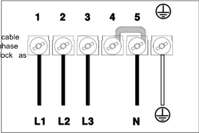
THREE-PHASE CONNECTION
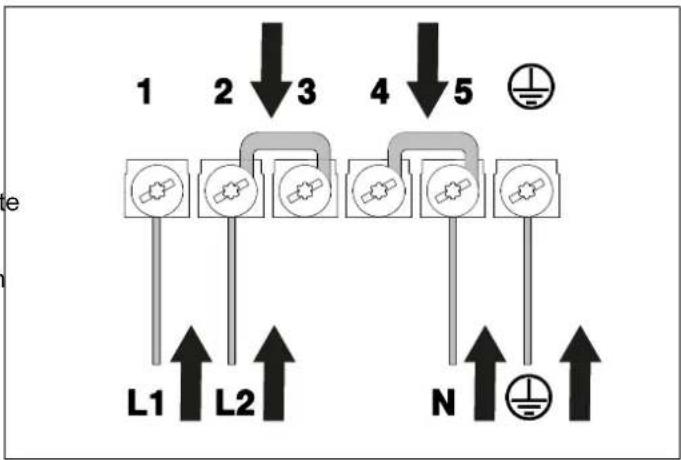
For the three-phase connection, replace the installed cable with the one supplied, remove the jumpers on the phase connections and connect the cable to the terminal block as shown in the images.
• Cable section: 5 x 1.5 ^2 mm
• Voltage: 220-240 / 380-415 V3N\~
text_image
1 2 3 4 5 cable phase lock as L1 L2 L3 NGENERAL SAFETY INSTRUCTIONS
- To be used, the appliance must be correctly installed kitchen on a suitable work surface, in accordance with current safety regulations and the instructions in this booklet.
- This appliance may be used by children from 8 years age and people with reduced physical, sensory or mental capabilities, or lack of experience and knowledge, provided they are supervised or instructed by adults responsible for their safety.
- Never try to put out a flame/fire with water. Switch th
- The appliance cannot be used on top of a dishwasher appliance and a tumble dryer: the steam could damage the electronic blanket components of the appliance.
- Have installation and servicing carried out by qualified personnel in compliance with applicable standards and legislation.
Do not try to repair the appliance yourself or without the assistance of a qualified technician. - If the power supply cable is damaged, contact technical support immediately and they will arrange for it to be replaced
- This appliance and its accessible parts become very hot during use.
- Do not touch heating elements during use.
- During use, do not place metal objects on the appliance, as they may become incandescent.
- Switch off the appliance after use.
- Do not leave objects on the cooking surfaces.
- Ensure that hot surfaces are allowed to cool before proceeding to clean the appliance.
- Do not use abrasive or corrosive detergents (e. g. scouring powders, stain removers and metallic sponges) on glass parts.
- Sudden and extreme changes in temperature can cause the glass to break – never pour cold liquids onto the hob when in use.
- In the event of breakage or cracking in the glass top, switch off the hob immediately and disconnect it from the power supply. Contact technical support.
- Damaged containers, those that are the wrong size, that overhang the edge of the hob or are badly positioned can cause serious injury.
- Use of the hob generates heat, humidity and combustion products; ventilate the room thoroughly when it is in operation.
- Do not modify this appliance.
- Do not insert anything in the slots.
- Do not obstruct ventilation openings and heat dispersal slots.
- Do not use the appliance as a space heater for any reason.
- Do not sit on the appliance.
- Do not use steam jets to clean the appliance.
- Keep children under 8 years of age at a safe distance unless they are constantly supervised.
• Children must not play with the appliance.
HOB DESCRIPTION
text_image
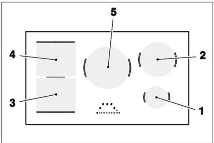
4 3 5 2 1Fig. 8
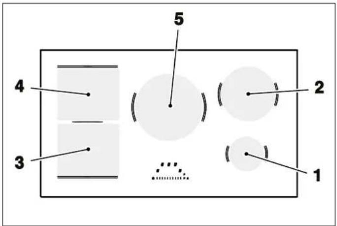
POSITION SIZE POWER
| 1 | ∅ | 145 | mm | 1.4 | kW | / | 1.8 | kW | ||
| 2 | ∅ | 200 | mm | 2.3 | kW | / | 3.0 | kW | ||
| 3 | 210 | x | 190 | mm | 2.1 | kW | / | 3.0 | kW | |
| 4 | 210 | x | 190 | mm | 2.1 | kW | / | 3.0 | kW | |
| 5 | ∅ | 250 | mm | 2.3 | kW | / | 3.0 | kW |
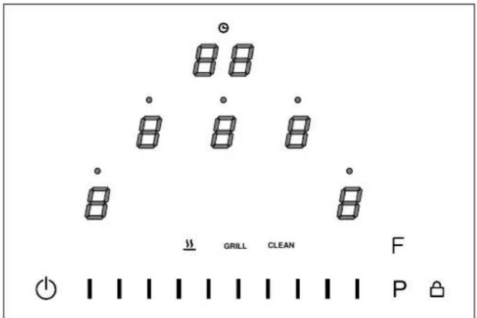
text_image
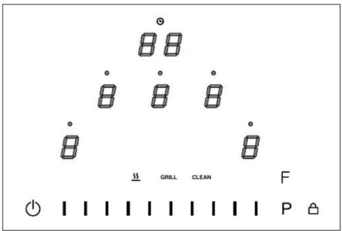
88 88 88 8 8 GRILL CLEAN F PFig. 9
ICON DESCRIPTION
| Switch the hob on and off | |
| Block controls | |
| Timer display | |
| Active timer | |
| Cooking zone power | |
| Functions button |
ICON DESCRIPTION
| P | Power button |
| Increases or decreases the power of a cooking zone, allows you to change settings and select options from the user menu | |
| $$ | Heating function |
| GRILL | Grill function |
| CLEAN | Clean function |
COOKING WITH INDUCTION
Under each cooking zone there is a coil called an indu The inductor generates a variable magnetic field using electrical power. When a pan is placed inside this magn field, the base heats up, producing the heat necessary 1 cooking.
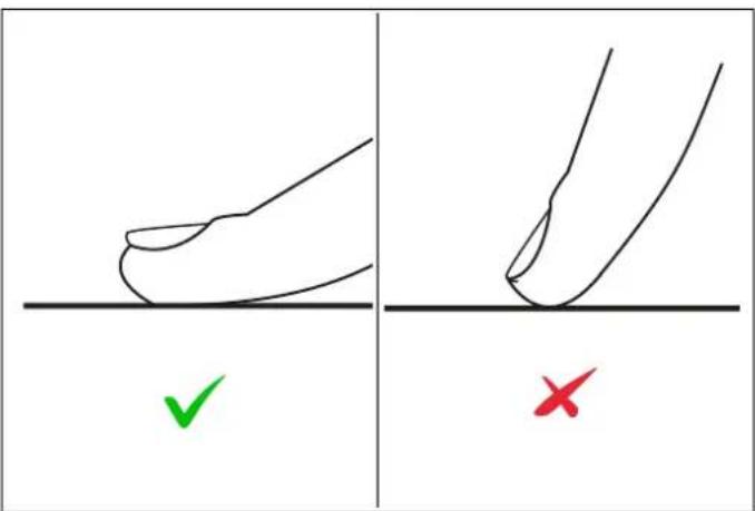
- The controls respond to touch, so there is no need to apply pressure.
- Use the pad of your finger and not the tip.
• Each detected touch produces an acoustic signal. - Make sure that the controls are always clean, dry and not covered by any object (such as a tool or cloth). a thin layer of water can make it difficult to use the controls.
text_image
Diagram showing two hand positions with check and cross marks, likely illustrating correct and incorrect movement methods.Fig. 10
SIZE FOR INDUCTION
CHOOSING THE MOST SUITABLE COOKING CONTAINERS
The induction plate automatically adapts to the size of the
pan: however, if the diameter of the pan is too small, do not use cooking containers with a rough bottom or plate will not work. The minimum diameter varies accorded base.
to the diameter of the plate.
| COOKING ZONE | MINIMUM VALUE | ||||||
| Round | coil | 145 | mm | 90 | mm | ||
| Round | coil | 200 | mm | 110 | mm | ||
| Round | coil | 250 | mm | 130 | mm | ||
| OCTA | coil | (single) | 110 mm | ||||
text_image
Diagram showing cooking process steps with checkmark and cross symbols indicating correct and incorrect statesFig. 11
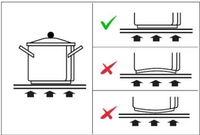
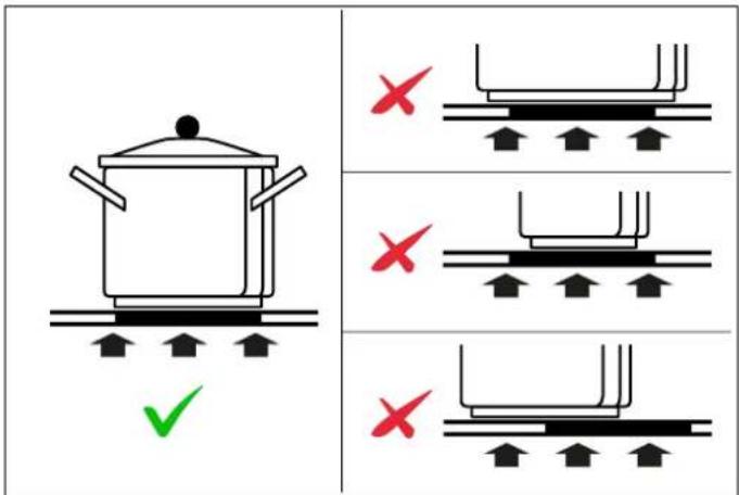
Make sure that the base of the pan is smooth, rests e on the glass and is the same size as the cooking area
Use pans of a suitable diameter, as shown in the figure the selected area. By using a slightly wider pan, the er will be used at maximum efficiency. If you use a smaller pan, the efficiency may be lower than expected. Always centre the pan on the cooking zone.
text_image
Diagram showing cooking process with cooking pot and three identical diagrams of a container being placed, each marked with red X symbols.Fig. 12
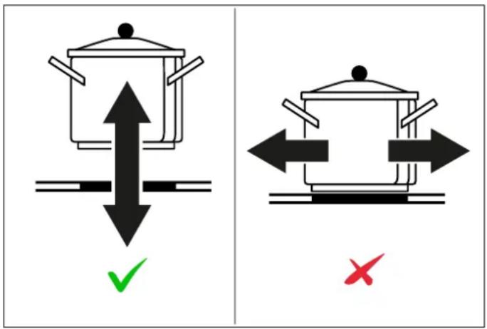
Always remove the pans from the hob by lifting them, (not drag them, as there is a risk of scratching the glass
text_image
Diagram comparing cooking methods: one with upward arrow and checkmark, the other with left-pointing arrows and a red X mark.Fig. 13
The bottom of the pan must be iron or steel/iron to the magnetic field necessary for the heating process.

NOTE
Pans made from the following materials are not suitable:
- glass
• porcelain
pottery - steel, aluminium or copper without magnetic bottom.
COOKING TIME LIMITATION
The appliance has an automatic device that limits the operating time.
If the cooking settings of the container are not changed, maximum operating time depends on the selected power level.
| POWER LEVEL | MAXIMUM OPERATING TIME [H] | |
| generate | Heating | 2 |
| 1 | 6 | |
| 2 | 6 | |
| 3 | 5 | |
| 4 | 5 | |
| 5 | 4 | |
| 6 1.5 | ||
| are | 7 1.5 | |
| 8 1.5 | ||
| 9 1.5 | ||
| P | 5 minutes | |
SWITCHING ON AND OFF
To switch on the hob press the button for 1 second When it switches on, the letters appear on the display
Make sure that the material of the pan is suitable for of the timer and the word in the special function induction. To check the material, place a magnet on the bottom of the pan: if it sticks, the pan is suitable for Only Timer and CLEAN can be activated without pans in induction. positioned on the hob.
If you do not have a magnet, to check if a pan is just pour a little water in it, place it on a cooking switch on the zone. If the symbol appears on the pan is not suitable.
When buying pans, make sure they are suitable for an induction hob.
zone and Induction does not work if there is no pan on the display cooking zone.
Place a pan (not empty) in the centre of the cooking zo use on you want to use. The cooking zone display will light up automatically.
You can then set the desired power.
- By sliding your finger on the slider from left to right you reach the desired value
- By directly touching the desired power level
- To switch off the cooking zone, touch the display of the cooking zone you want to switch off
- Slide your finger on the slider from right to left until reaches 0
- By directly touching the area of the slider correspond to 0 (last mark on the left)
POWER FUNCTION
This function allows you to have more power on a zone for a limited time (for example to reduce the takes to heat water).
To activate it, directly touch the button. The Power function remains active at maximum for 5 minutes, which the power is automatically lowered to 9.
To deactivate the booster, set a lower power level.
MULTIZONE
The Multizone function allows you to combine two adjacent cooking zones to form a single larger area, ideal for using long or rectangular pans such as grill pans, griddles or fish kettles.
The function can be activated on adjacent cooking zones located on the left side of the hob.
The Multizone function is automatically activated if a pan is detected that covers both cooking zones.
It is possible to activate the function manually by pressing the controls of the corresponding cooking zones at the same time. A tone confirms activation. After activation, the power can be adjusted using the slider and selecting the front area, ensuring even cooking over the entire extended area. To deactivate Multizone, press the controls of the two zones at the same time. The two zones will return to functioning separately.
AUTOMATIC HEATING FUNCTION
cooking function allows you to heat a cold pan (not empty) time maximum heat and automatically return to the previously set cooking level.
To activate it, press the desired power level (from 1 to 3 seconds. The automatic cooking symbol will appear on the display. Once the heating time is over, the power level will return to the preset level.
The time during which the cooking zone is heated at maximum power depends on the selected cooking level.
| ideal | ||
| POWER LEVEL | AUTOMATIC HEATING (SECONDS) | |
| ones | 1 | 48 |
| 2 | 144 | |
| an is | 3 | 230 |
| 4 | 312 | |
| ssinge | 5 | 408 |
| 6 | 120 | |
| the the ended | 7 | 168 |
| 8 | 216 | |
| the two | 9 | / |
| P | P | / |
The function can be deactivated manually by selecting a lower power level than the one initially set.
AUTOMATIC SWITCH-OFF
The hob switches off automatically 20 seconds after all cooking zones have been switched off.
TIPS ON THE POWER TO BE USED FOR VARIOUS COOKING METHODS
The use of power can vary according to experience and cooking habits.
| MAXIMUM POWER | P | Quick heating | Quickly raising the temperature of food to boiling point in the case of water, or quickly heating up cooking liquids |
| 8-9 | Frying, boiling | Browning, starting to cook, frying frozen products, quick boiling | |
| HIGH POWER | 7-8 | Browning, light-frying, boiling, grilling | Light-frying, keeping at a high boil, cooking and grilling (for short periods, 5-10 minutes) |
| 6-7 | Browning, cooking, stewing, light-frying, grilling | Light-frying, keeping at a slow boil, cooking and grilling (for medium periods, 10-20 minutes). Preheating pans | |
| MEDIUM POWER | 4-5 | Cooking, stewing, light-frying, grilling | Stewing, keeping at a low boil, cooking (for long periods), creaming pasta |
| 3-4 | Cooking, simmering, thickening, creaming | Prolonged cooking (rice, mushrooms, roasts, fish) in the presence of accompanying liquids (water, wine, stock, milk), creaming pasta | |
| 2-3 | Cooking, simmering, thickening, creaming | Prolonged cooking (less than a litre: rice, sauces, roasts, fish) in the presence of accompanying liquids (water, wine, stock, milk) | |
| LOW POWER | 1-2 | Melting, defrosting, keeping warm, creaming | Melting butter, gently melting chocolate, defrosting small products |
| 1 | Melting, defrosting, keeping warm, creaming | keeping small portions of freshly cooked food warm or keeping serving dishes at the right temperature and creaming risotto |
POWER MANAGEMENT
TIME FUNCTIONS
The hob is equipped with a power management module MINUTE-MINDER
that optimises consumption, avoiding overloading the electrical mains.
When it switches on, the letters appear on the timer display.
If more than one zone is active and the power consumed
exceeds the power supply limit, this function distributes the timer display and use the slider to set first available power among all the cooking zones (connected to minutes and then the desired tens of minutes. After 2 seconds the symbol lights up and the countdown
The electronic control tries to maintain the maximum
of power that can be delivered. Priority is given to the last
zone set, the displays of the other zones flash indicating switch off or change the cooking time, repeat the same the new value to which they will be reset. procedure and change the time (possibly setting it to 0).
tting switch off or change the cooking time, repeat the sa procedure and change the time (possibly setting it to 0).

CAUTION
In the case of power limitation set at a very low level, the electronic control could switch off a cooking zone because it is not possible to redistribute the power.
NOTE
The timer can be set and only works whe all the cooking zones are switched off.

CAUTION
Lower power levels are reached by switching the inductor on and off at pre-s-intervals. This method of operation minimises the heat supplied to food when cooking at low temperatures.
If you want to set an end of cooking timer for a zone
sctActivate the zone
2) Press the timer display
3) Press the timer display and use the slider to set first minutes and then the desired tens of minutes
4) After 2 seconds the symbol above the display of the corresponding cooking zone lights up and the countdown begins
5) At the end of the countdown, a tone sounds and the cooking zone is switched off.
To switch off or change the cooking time, repeat the sa procedure and change the time (possibly setting it to 0).

NOTE
If more than one timer is set, the timer w always display the lowest remaining time
PAUSE
With this function it is possible to suspend the operation ALL cooking zones.
Press the button for 3 seconds, all the zones will switch off and the PAUSE symbol will appear on the display, the set power levels will be memorised.
To reactivate the hob, press for 3 seconds and then press any button (except the button). At this point, all zones will start to function as before.
The appliance switches off automatically after a 10-minute pause
RESIDUAL HEAT
The residual heat indicator is a safety feature.
Once cooking is finished, the cooking zone may be high temperature. The symbol appears on the display corresponding to the hot zone.
The H symbol may also appear:
• for nearby cooking zones, even if they are not in use
- when placing hot pans on the cold cooking zone
The symbol disappears when the zone reaches a temperature below 60^ C
CHILD LOCK
This function allows you to lock the interface to prevent the can be switched back on. hob from being used by children.
Press the display of a cooking zone for 3 seconds then
slide the slider from 0 to 9. Complete this procedure with function allows you to maintain the temperature of 10 seconds. pan at 70°C.
The indicationLappears on all displays.
Repeat the same sequence to deactivate the function.
KEYPAD LOCK
This function allows you to lock the keypad during use, avoid accidentally changing settings.
To activate, press the button, which lights up to indicate the active function.
To deactivate the function, press the button again.
PAN SENSOR
When a pan is placed on a cooking zone with the hob
switched on, the controls for that cooking zone are
automatically activated and the desired power level can set directly.
The function can be disabled via the user menu.
With the function disabled, after positioning the pan you must choose the relative cooking zone before setting the power.
NO PAN
If the pan is removed from a cooking zone without turn off the zone, the display indicates that there is no pan at a

CAUTION
If the zone is not turned off, the hob remains active, so it could heat up another pan placed on the same zone by mistake.
DISPLAY OVERTEMPERATURE
If a hot object is placed on the interface, the interface go into protection mode, switching off the hob completely and indicating ER21.
When the temperature drops below the limit of 85^ C, the
WARMING
Twish function allows you to maintain the temperature of pan at 70°C.
Activate the cooking zone on which you want to set the function, press the function button F. The function is
activated and Warming appears on the display.
To deactivate or change the power, select the corresponding cooking zone and set the desired power
sever using the slider.
The function can also be set in the case of active brid zones.
GRILL
This special function facilitates the grilling of food.
Place the grill pan on the multizone and select it.
Press the function button twice until the function is activated.
Set the power level using the slider:
• for levels 1-3 one mark will appear on the display
for levels 4-6 2 marks will appear on the display
thefor levels 7-9 3 marks will appear on the display
CLEAN
This function locks the keypad for 30 seconds to allow cleaning.
Without selecting cooking zones, press the Fbutton to activate the CLEAN function.
The countdown will appear on the display, reminding you how long the keypad remains locked.
USER MENU
The user menu allows you to customise some basic settings of the induction hob.
To enter the user menu, the hob must be switched off
1) Switch on the hob by pressing
2) Press the button again
3) The hob is switched off, the button starts to flash
4) With the button pressed, press the cooking zone buttons in sequence in a clockwise direction (starting from the front left button) - each time a button is 2 it will be confirmed by a beep
5) Release the button
6) The display at the back left shows the letters U and 0 alternately
7) To choose the desired function, use the slider by pressing the corresponding mark (the slider function not active)
FUNCTIONS/LEVELS
• U0 Total power set for each phase
- U2 Tone volume for when buttons are pressed (the volume of the button cannot be changed)
• U3 Timer volume 0–3
- U4 Display brightness 0–9 (1 maximum brightness – 9 minimum brightness)
- U5 Timer animation 0 (no animation) - 1 (countdown in the last 60 seconds)
- U6 Automatic pan detection active 1 Automatic pan detection deactivated 0
- U7 Timer signal length 0 (120 seconds) - 1 (10 seconds) - 2 (no alarm tone)
The front left display shows the set level of the function
Press the front left display and use the slider to press the desired level.
To exit the menu without saving - press the button
To exit the menu and save the modified settings - press the
button for at least 2 seconds (the changes are saved and the hob switches off)
SERVICE MENU

NOTE
The service menu should only be used by the installer or specialised personnel.
To enter the service menu, the hob must be switched o and powered for less than 2 minutes
1) With the P button pressed, press the cooking zone buttons in sequence in a counterclockwise direction (starting from the front right button) - each time a butt is pressed, it will be confirmed by a beep
2) Release the P button
3) The display at the back left shows the letters C and 0 alternately
4) To choose the desired function, use the slider by pressing the corresponding mark (the slider function is not active)
FUNCTIONS
• C6 Demo mode 1 - demo mode active 0 - deactivat
• C8 Power management
The front left display shows the set level of the function
1) Press the front left display and use the slider to press desired level.
2) To exit the menu without saving - press the button.
3) To exit the menu and save the modified settings - press
the ⏻ button for at least 2 seconds (the changes are saved and the hob switches off)
POWER LIMITATION
To avoid overloading the power line, it is possible to maximum power absorbed by the hob. See SERVICE MENU

CAUTION
The reduction of the maximum power could mean that it is not possible to use all the zones at the same time, or that the boost function has to be set for some zones.
Table 1 HOB 90
| POWER CONFIGURATION MANAGEMENT | NUMBER OF PHASES | VOLTAGE (V) | POWER LIMIT PER PHASE (W) | |||
| 0 | 3 | 230 | 3700 | |||
| 1 | 2 | 230 3700 | ||||
| 2 | 1 | 230 | 6700 | |||
| 3 | 2 | 230 | 3000 | |||
| 4 | 1 | 230 | 6000 | |||
| 5 | 1 | 230 5500 | ||||
| 6 | 2 | 230 | 2400 | |||
| 7 | 1 | 230 | 4200 | |||
| 8 | 1 | 230 | 3700 | |||
| 9 | 1 | 230 2400 | ||||
REPLACING COMPONENTS
Disconnect the appliance from the power mains before carrying out any maintenance procedure.
Contact an authorized service center if functional and electrical components require replacement.

WARNING
If the power cable requires replacement, the installer/maintenance technician must use a cable of the type and with the cross-section as per the table and leave the earth lead about 2 cm longer than the phase leads. The instructions given for the initial electrical connection must also be complied with.
Permitted cable types: H05VV-F, H05RR-F, H07RN-F
| TYPE OF CONNECTION | VOLTAGE | CABLE SECTION |
| SINGLE-PHASE | 220-240 V 5x2.5 mm | ^2 |
| TWO-PHASE | 220-240/380- 415 V2N~ 4x4 mm | ^2 |
| THREE-PHASE | 220-240/380- 415 V3N~ 5x1.5 mm | ^2 |
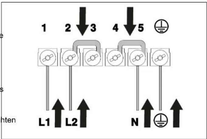
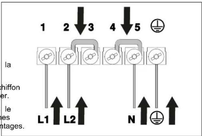
For the two-phase or three-phase connection, follow the procedure below:
1) Turn the hob over and place it on a cloth or other soft surface to avoid scratching it.
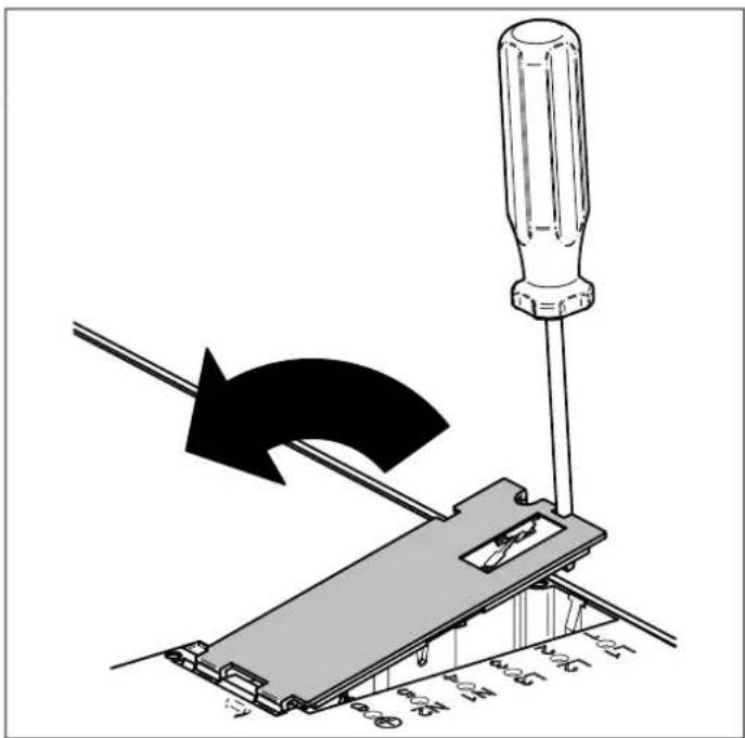
2) Remove the terminal block cover and the cable clamp using a screwdriver. Unscrew the cable fixing clamps and remove the cable and jumpers.
3) Depending on the connection required, prepare the jumpers, insert the cables into the terminals and tighten the screws adequately. Refit the cable clamp and terminal block cover.
text_image
Diagram illustrating screwdriver tool application on a mechanical component with directional arrow indicating motionFig. 14
Two-phase connection 4x4 m ^2 m220-240 / 380- 415V 2N\~
flowchart
graph TD
    A["Component 1"] --> B["L1"]
    C["Component 2"] --> D["L2"]
    E["Component 3"] --> F["N"]
    G["Component 4"] --> H["Ground Symbol"]
    I["Component 5"] --> J["Ground Symbol"]
    style A fill:#f9f,stroke:#333
    style C fill:#f9f,stroke:#333
    style E fill:#f9f,stroke:#333
    style G fill:#f9f,stroke:#333
    style I fill:#f9f,stroke:#333
    style B fill:#ccf,stroke:#333
    style D fill:#ccf,stroke:#333
    style F fill:#ccf,stroke:#333
    style H fill:#ccf,stroke:#333
    style J fill:#ccf,stroke:#333
Fig. 15

CAUTION
Make sure that the cables and jumpers are correctly fixed and that the screws are properly tightened.
For the different electrical connection possibilities, use the brass connection jumpers already assembled in the terminal block.
POWER LIMITATION
Power limitation defines how much power is used by the hob in total, within the limits of the fuses for domestic installation.
The hob is preset to the maximum power level.
To set a different power limit, see chapter POWER FUNCTION, obviously the higher the power set, the greater the number of functions and power levels that can be simultaneously on the cooking zones.
NOISE DURING OPERATION
A pulsating or continuous hum during operation is normal and can vary in intensity depending on the different types of pans and the power setting.
The cooling fan protects the electronics from overheating, so it is normal to hear it running even after switching off the induction hob.
CLEANING THE APPLIANCE
Before performing any manual cleaning operation, wait for all parts to cool down and check that the hob is switched off or in cleaning mode.
THINGS TO AVOID
Do not use steam to clean the hob, as the steam could reach the electronic components and cause a short circuit.
All surfaces can become discoloured or damaged if cleaning agents that are too aggressive or unsuitable are used.
CLEANING THE DECORATIVE FRAMES
Clean the parts with soapy water and then dry them with a soft cloth. The shine can be maintained by periodic use of commonly available products. Never use scouring powders or pads.
CLEANING THE GLASS
To degrease, use washing-up liquid and vinegar, then rinse; otherwise, clean with washing-up liquid, rinse, then pass over with a moist cloth before drying.
To remove encrusted food, soak with soapy water or washing-up liquid for a few minutes. After a few minutes, rinse off then dry with a soft cloth.
Avoid anti-limescale, abrasive and multi-purpose products, as they will affect the look of the glass after a while.
BEHAVIOUR POSSIBLE CAUSES
| The hob will not turn on | There is no power supply or it could be interrupted (for example, blown fuse) |
| The hob does not heat up | DEMO mode is activated, see section SERVICE MENU |
| The letter L appears on the display | Child lock is activated - see relevant section CHILD LOC |
| No pan symbol The pan has been removed from the cooking zone | |
| Symbol A alternates with the power level The automatic cooking system has been set | |
| The power of the chosen cooking zone cannot be selected | The pan has not been recognised (it may have been positioned incorrectly, it may not be suitable for induction cooking or its diameter may be too smallThe power level selected is higher than the maximum power level set for the hob |
| Residual heat symbol does not light up | The zone just used for cooking has not reached a high temperature |
| The cooking zones change power autonomously | See section POWER MANAGEMENT |
| When a cooking zone is switched on, another one off | Switches See section POWER MANAGEMENT |
| A cooking zone or the entire hob turns off | The hob is overheated, check that there are no obstructions to the lower cooling system (e.g. bulky material inside a drawer under the hob)If the problem persists, contact customer support |
| Food does not heat up in the expected time | Although the pan is compatible with induction cooking, it conducts heat poorlyThe pan is much smaller than the cooking zone and on receives part of the possible power |
| When the hob is on, you can hear a slight ticking | The noise is due to the automatic pan sensor function (sound relevant section) |
| After switching off the hob, you can hear noises | The cooling fan works until the electronic components have cooled down completely, after which it switches off automatically |
| The control panel becomes warm to the touch | A pan that was too big was placed in the front cooking zones near the control area |
| The food in the pan alternates between boiling and boiling | Innis absolutely normal at the lowest power levels (below level 6) (see section POWER MANAGEMENT |
The cooking platform has dedicated error codes for quick and efficient diagnostics. The Lite Slider shows the error codes on the 7-segment displays of the cooking zones.
An error code always begins with the letters E... or ER..., depending on the electronic component that generated the error:
- Error codes that begin with E... refer to a specific zone or component.
- Error codes that begin with ER... refer to the entire hob.
Before calling customer service, make sure that the appliance is connected correctly; the following cases are not covered by the warranty
- Damage caused by improper use, storage or maintenance.
• Damage caused by unauthorised disassembly and repair.
• Damage caused by improper use.
• Use of the induction hob for commercial purposes.

NOTE
If an anomaly occurs, the induction hob automatically goes into protection mode and displays corresponding protection codes indicated in the table below.

NOTE
For other errors, contact technical support.
ERROR CODE BEHAVIOUR POSSIBLE CAUSES REMEDIES
| ER03 | The hob switches off 10 seconds | after Water or pans placed on user interface | Remove the water or pans from the glass |
| ER21 | The hob switches off | The temperature sensor on the user interface has detected a temperature >85°C | Let the hob cool down (the error will disappear if the temperature drops below 75°C). Check the thermal insulation of the user interface |
| E2 / ER21 | / | Overtemperature / switching off | / |
| U400 | / | Incorrect 400V connection, not suitable for the grill board | / |
WARRANTY AND SERVICE

Bertazzoni is committed to providing the highest quality service to our customers. In the unlikely event that your product should have a manufacturing defect, please contact our service team at:
https://uk.bertazzoni.com/more/care-service
You will be requested to provide product information, proof of purchase, a photo of the silver data label and a description of the issue. Please have this information ready.
CUSTOMER SERVICE
CONVENTIONAL WARRANTY CERTIFICATE: WHAT DO I NEED TO DO?
Your product is guaranteed, on the terms and conditions set forth in the certified supplied with the product and PRO accordance with the provisions of current law, for a period of 24 months from the date of delivery of the appliance.
As required by the aforesaid Legislative Decrees, you must conserve the duly compiled warranty certificate, so that it can be shown to the Authorised Service Partner if necessary together with a fiscally valid document issued by the dealer at the time of purchase (delivery note, invoice, fiscal receipt, etc.) which carries the dealer's name, the delivery date, identification of the product and the price of sale
It is understood that, unless proven to the contrary, since conformity defects which emerge within six months after delivery of the appliance are assumed to have already existed at that date, unless this assumption is incompatible with the nature of the appliance or the nature of the conformity defect, after checking the warranty cover, the Bertazzoni S.p.A. Authorised After-Sales Service will do the necessary work without charging for the call-out, labour and parts. However, for the subsequent eighteen months of the warranty period, consumers intended to claim remedies granted under the warranty shall be responsible for proving that the conformity defect has been present ever since delivery; therefore, if consumers are unable to provide this proof, the warranty conditions shall not be applied and therefore the Bertazzoni S. p. A. Authorised After-Sales Service will do the work required and charge all the relative costs to the consumer.
ANOMALIES AND MALFUNCTIONS: WHO DO I CONTACT?
The service partner is always ready to assist you with all necessary explanations, but in case of anomalies or malfunctions affecting your product you are urged to perform all the checks listed in the instruction manual before contacting the Authorised After-Sales Service.
To order parts or accessories, telephone our service and parts department.
FINDING YOUR NEAREST SERVICE CENTRE
If the problem persists, you can find your local Authorise Service Partner at any time by contacting your dealer or distributor or visiting www.bertazzoni.com.
PRODUCT MODEL: WHERE CAN I FIND IT?
od en talking to the Authorised Service Partner, you must te the product's model and its serial number (10 figui which are provided in the instruction manual (silver sticks on the decal applied to the product. This will help to oid unnecessary call-outs and above all save the relati
DU BUREAU DU PRÉSIDENT
LECTURE DU MANUEL 73
INTRODUCTION ET SÉCURITÉ 73
IDENTIFICATION DE L'APPAREIL 74
INFORMATIONS GÉNÉRALES DE SÉCURITÉ 74
AVERTISSEMENTS 76
RESPONSABILITÉ DU FABRICANT 76
PROTECTION DE L'ENVIRONNEMENT 76
INSTALLATION 77
MISES EN GARDE IMPORTANTES 77
AVERTISSEMENTS D'UTILISATION 77
INTÉGRATION DE LA PLAQUE DE CUISSON 78
INSTALLATION AU-DESSUS D'UN FOUR ENCASTRÉ 80
INSTALLATION AU-DESSUS D'UN LOGEMENT OU DE TIROIRS 80
POSE AFFLEURANTE 81
FIXATION DE LA PLAQUE DE CUISSON 81
VENTILATION AMBIANTE 82
BRANCHEMENT ÉLECTRIQUE 82
BRANCHEMENTS POSSIBLES AVEC LE CORDON FOURNI 83
UTILISATION 84
CONSIGNES GÉNÉRALES DE SÉCURITÉ 84
text_image
1 Bertazzoni Spa Via Palazzina, 8 42016 Guastalla (RE) Italy www.bertazzoni.com UK CA CE ATTENTION: This appliance must be installed in accordance with it currently in force and must be only used in well ventilated premises instructions before installing or using this appliance. 2 PXXXXXXXXXX Produc I Type : Inducio n Built-i n Hob Factor y Model:PXXXXXXXXXXX Rated Voltage : 220-24 0 V~ Rated Frequency : 50/6 0 Hz Total Power r (kw) : 7.0 kw (230v~) : CLASS I Made in China SN:XXX X 0000 1 3 regulations Read the 8 05 797 1 1050 694Fig. 1
natural_image
Cross-sectional diagram of a mechanical assembly with hatched areas indicating material sections (no text or labels)Fig. 5

NOTE
text_image
88 8 8 8 8 8 8 GRILL CLEAN F PFig. 9
text_image
Diagram showing two hand positions with check and cross marks, likely illustrating correct and incorrect states of a rule or procedure.Fig. 10
DIMENSION POUR L'INDUCTION
text_image
Diagram showing cooking process steps with checkmark and cross symbols indicating correct and incorrect statesFig. 11
text_image
Diagram showing cooking process with a pot and checkmark, alongside three diagrams of a container being placed on different surfaces.Fig. 12
text_image
Diagram comparing cooking methods: one with upward arrow and checkmark, the other with left-pointing arrows and a red X mark.Fig. 13
text_image
Diagram illustrating a screwdriver operating a mechanical device with a black arrow indicating the process direction.Fig. 14
- Branchement biphasé 4x4 m ^m 220-240 / 380- 415V 2N\~
flowchart
graph TD
    A["1"] --> B["L1"]
    C["2"] --> D["L2"]
    E["3"] --> F["N"]
    G["4"] --> H["+"]
    I["5"] --> J["⊥"]
    style A fill:#f9f,stroke:#333
    style C fill:#f9f,stroke:#333
    style E fill:#f9f,stroke:#333
    style G fill:#f9f,stroke:#333
    style I fill:#f9f,stroke:#333
    style B fill:#ccf,stroke:#333
    style D fill:#ccf,stroke:#333
    style F fill:#ccf,stroke:#333
    style H fill:#ccf,stroke:#333
    style J fill:#ccf,stroke:#333
Fig. 15
LIMITATION DE LA PUISANCE
https://uk.bertazzoni.com/more/care-service
BEVESTIGING KOOKPLAAT 115
VENTILATIE VAN DE RUIMTE 116
text_image
1 2 Bertazzoni Spa Via Palazzina, 8 42016 Guastalla (RE) Italy www.bertazzoni.com UK CA CE PXXXXXXXXXX Produc t Type : Inductio n Built-i n Hob Factory y Model:XXXXXXXXXX Rated Voltage : 220-24 0 V~ Rated Frequency : 50/60 Hz Total Power r (kw) : 7.0 kw (230v~) : CLASS I Made in China SN:XXX X 0000 1 ATTENTION: This appliance must be installed in accordance with the currently in force and must be only used in well ventilated premises instructions before installing or using this appliance. 3 regulations Read the 8 45797 1415069RAfb. 1
natural_image
Cross-sectional diagram of a mechanical assembly with hatched areas and a central curved line (no text or symbols)Afb. 5

OPMERKING
BEVESTIGING KOOKPLAAT
text_image
at 2 mm 2 mmAfb. 7
BESCHRIJVING KOOKPLATEN
text_image
4 3 5 2 1Afb. 8
POSITIE AFMETING VERMOGEN
| 1 | 145 mm | 1,4 kW / 1,8 kW | |
| 2 | 200 mm | 2,3 kW / 3,0 kW | |
| 3 | 210 x | 190 mm | 2,1 kW / 3,0 kW |
| 4 | 210 x | 190 mm | 2,1 kW / 3,0 kW |
| 5 | 250 mm | 2,3 kW / 3,0 kW |
text_image
88 88 8 8 8 8 8 GRILL CLEAN F PAfb. 9
SYMBOOL BESCHRIJVING
text_image
Diagram showing two hand positions with check and cross marks, likely illustrating correct and incorrect movement methods.Afb. 10
GROOTTE VOOR INDUCTIE
text_image
Diagram showing cooking process steps with checkmark and cross symbols indicating correct and incorrect statesAfb. 11
text_image
Diagram showing cooking process steps with cooking pot and valve symbols, marked with checkmark and red X marks indicating failure or error.Afb. 12
text_image
Diagram comparing cooking methods: one with upward arrow and checkmark, the other with left-pointing arrows and red X mark.Afb. 13
Table 1 KOOKPLAAT 90
| BEHEER VAN VERMOGENSCONFIGU-RATIE | AANTAL FASEN | SPANNING (V) | VERMOGENSLIMIET PER FASE (W) | |||
| 0 | 3 | 230 | 3700 | |||
| 1 | 2 | 230 | 3700 | |||
| 2 | 1 | 230 | 6700 | |||
| 3 | 2 | 230 | 3000 | |||
| 4 | 1 | 230 | 6000 | |||
| 5 | 1 230 5500 | |||||
| 6 | 2 | 230 | 2400 | |||
| 7 | 1 | 230 | 4200 | |||
| 8 | 1 | 230 | 3700 | |||
| 9 | 1 | 230 | 2400 | |||
VERVANGING VAN DE ONDERDELEN
text_image
Diagram illustrating a screwdriver tool interacting with a mechanical device, showing a black curved arrow indicating motion or change.Afb. 14
https://uk.bertazzoni.com/more/care-service
24 PRODUCTMODEL: WAAR KUNT U DIT VINDEN?
© 2025 BERTAZZONI. All rights reserved.
3101029_v.01