LMDLN-AW1 - Fridge DAIKIN - Free user manual and instructions
Find the device manual for free LMDLN-AW1 DAIKIN in PDF.

| Brand | Daikin |
| Model | LMDLN-AW1 (LMD series) |
| Category | Monobloc refrigeration unit for cold room |
| Product type | Professional refrigerator / refrigeration unit |
| Power supply | 230 V / 1 / 50-60 Hz (single-phase) or 400 V / 3 / 50 Hz (three-phase) depending on model |
| Refrigerant | HFC (non-flammable) |
| Compressor | Hermetic, reciprocating |
| Defrost | Automatic by hot gas injection (standard) |
| Temperature control | Electronic controller with digital display and setpoint adjustment |
| Display | Led: compressor, defrost, fan, alarm, auxiliary |
| Electrical protections | Thermal protection of fans, high pressure switch (auto-reset) |
| Safety | Side and top brackets, fan protection grilles |
| Wall-mounted installation | Mounting in a cold room wall, silicone around the insulating gasket |
| Condenser cleaning | Blow air from inside to outside, machine stopped |
| Routine maintenance | Periodic condenser cleaning, check electrical contacts |
| Interventions reserved for professionals | Refrigeration circuit, replacement of electrical components, mechanical repairs |
| Spare parts | Order with the serial number on the machine plate |
| Disposal | In accordance with local legislation: fluid recovered by an approved company |
| Documents provided | Installation and operation manual, wiring diagram |
Frequently Asked Questions - LMDLN-AW1 DAIKIN
User questions about LMDLN-AW1 DAIKIN
0 question about this device. Answer the ones you know or ask your own.
Ask a new question about this device
Download the instructions for your Fridge in PDF format for free! Find your manual LMDLN-AW1 - DAIKIN and take your electronic device back in hand. On this page are published all the documents necessary for the use of your device. LMDLN-AW1 by DAIKIN.
USER MANUAL LMDLN-AW1 DAIKIN
Monoblock System for Refrigeration
Installation & Operating Manual Monoblock for Refrigeration
natural_image
Illustration of a forklift and two gas cylinders with upward arrows indicating motion (no text or symbols)
AVVERTENZE
-Inject silicone all around the panel opening. Apply silicone on the upper side before positioning the unit.
(LMD MF350-400-600-750/ LF500-600-750-M00)

AVVERTENZE
- Safety recommendations
- Table of warning and attention plates
- Description of the unit
- Operation
- Handling
6. Installation
6.1 Plates
6.2 Dimensions
6.3 Location
6.4 Free room
6.5 Installation
6.6 Safety devices
6.7 Cleaning
7. Connecting the unit
7.1 Electric connection
8. Electric controls
8.1 Control panel
8.2 Pushbuttons and signals on the electronic control panel
8.3 Instruction to display the parameters
9. Checks, regulations and adjustments
9.1 Starting
10. Wiring
11. Maintenance and repairs
12. Routine maintenance
12.1 Periodical maintenance
12.2 Service operations to be carried out by qualified technicians or by the manufacturer
12.3 Troubleshooting
12.4 Alarms
13. How to order spare parts
14. How to dispose of the packing
15. How to dispose of the unit
Thank you for choosing Daikin.
Please read these instructions carefully. They provide details and advice on the correct method of installing, using and maintaining this unit, in order to obtain maximum reliability, efficiency and long life.
1 SAFETY RECOMMENDATIONS
When installing and using the unit please follow the recommendations listed here below.
- Installation shall be carried out in strict compliance with the diagrams and instructions supplied by the manufacturer.
• Damages due to improper connections are excluded.
• The electric system available where the unit is installed shall meet the relevant standards in force. - Maintenance shall be effected by trained personnel or by the manufacturer according to the provisions supplied by EN378.

WARNING
Use safety gloves to protect your hands from possible cuts.
The user is strongly recommended to contact the manufacturer before attempting any intervention on the unit and any use not corresponding to the manufacturer's indications (in particular as for the field of application) and to enquire about the possible dangers and contra-indications connected with an improper use of the machine.
- The unit shall be used following these instructions and sticking to the destination of use indicated by the supplier. Any incorrect use can result in damages to the unit and represents a serious danger for people's health.

ATTENTION
The unit is not suitable for working in explosive environments.
Therefore the use of the unit in an explosion-dangerous atmosphere is absolutely forbidden.

ATTENTION
The unit is not suitable for working in salty environments. In such a case protect condenser and evaporator with appropriate means.
When maintenance involves operations on the refrigerating circuit, empty the system and let it reach the atmospheric pressure.

WARNING
Do not discharge the refrigerant in the atmosphere. It must be recovered by spot technicians using suitable equipment.
• Quantity and quality of the refrigerant to be charged are indicated on the data plate.
- Do not use refrigerants of different kind (especially inflammable fluids, for example hydrocarbons) or air.
- Do not modify or alter the refrigerating circuit or its components (for example: welding on compressor body)
- The final user shall protect the system from external fire dangers.
2 Table of warning and attention plates
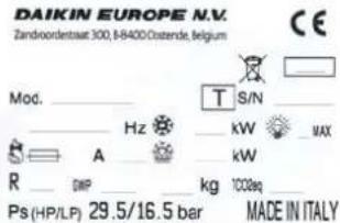
 | Refrigerant |
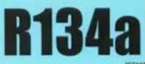 | Refrigerant |
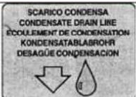 | Condensate drain line |
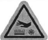 | Attention: hot or cold parts |
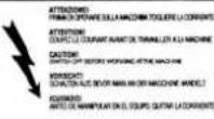 | Attention: switch off before operating on the unit. |
 | Attention: danger of electrocution |
 | Connect this cable to a circuit breaker, never to the main line directly. |
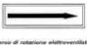 | Direction of rotation |
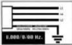 | Colours of supply cable wires |
 | Attention - important : clean the condenser periodically by blowing air from the inside outwards.Stop the unit before cleaning. |
3 Description of the unit
The LMD series includes air-cooled or water-cooled (optional) condensing units built on the basis of the single-block principle. They consist of:
- an evaporator installed inside the cold room;
- an insulating panel;
- a condensing unit placed outside the cold room;
- an electric control panel placed on the condensing unit.
4 Operation
LMD single blocks are compression units where cold is produced by vaporizing a liquid refrigerant (HFC type) at low pressure in a heat exchanger (evaporator). The resulting vapour is brought again into the liquid state by mechanical compression at a higher pressure, followed by cooling in another heat exchanger (condenser). The compressor is hermetic, with reciprocating motion, supplied with single-phase or three-phase power.
Defrost takes place automatically in pre-set cycles, by injecting hot gas ( standard); manual defrost is also possible.
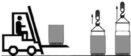
5 Handling
The unit can be handled by lifting and transport means.
natural_image
Illustration of a forklift and two stacked cylindrical objects with upward arrows indicating motion (no text or symbols)
WARNING
Make sure that no one is in transit in the operating area of the lifting/transport means to prevent any possible accidents to people.

If the unit is in a wooden case or crate, sling the packing properly before handling it.

Lifting speed shall be such as not to make the packed unit oscillate dangerously and possibly fall.
6 Installation
6.1 Plates
The unit is supplied with warning and attention plates as listed in the relevant table.
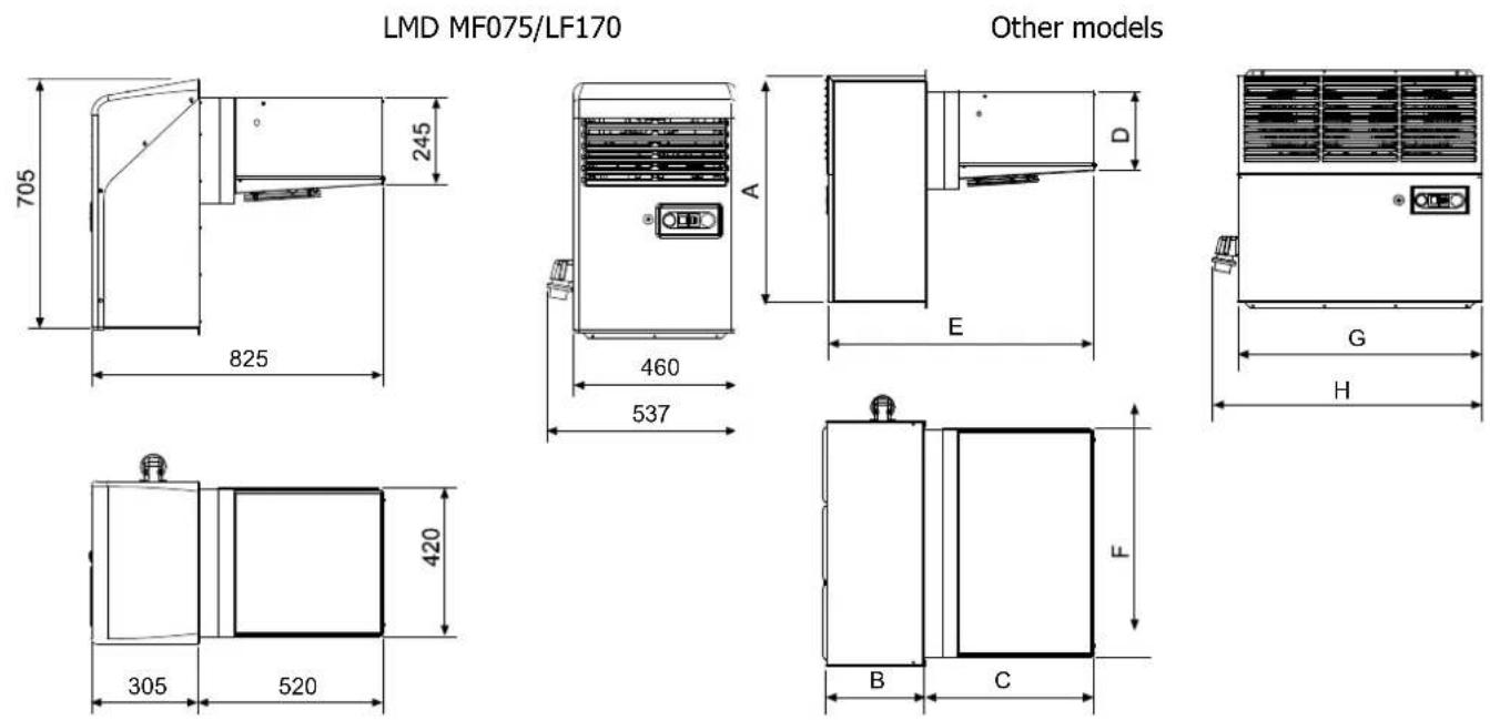
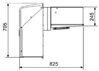
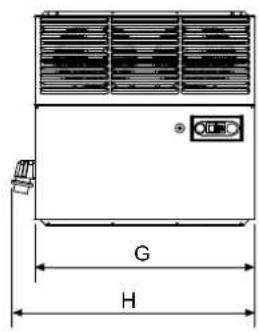
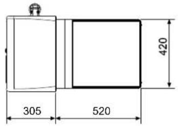
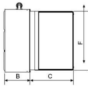
6.2 Dimensions
| A | B | C | D | E | |||
| LMD MF100-120/LF200 695 | 305 490 245 | 825 720 | 754 832 | ||||
| LMD MF230/LF350 800 400 700 | 385 11 | 00 720 | 754 832 | ||||
| LMD MF350/LF500 857 440 700 | 385 11 | 00 1120 | 1128 | 1210 | |||
| LMD MF400-600/LF600-750 857 440 | 970 380 | 1410 | 1560 1 | 598 1698 | |||
| LMD MF750/LFM000 857 490 1090 460 | 1580 16 | 00 1638 | 1738 |
F
6.3 Location
To obtain optimal operation of the unit act as follows:
A) Place the unit in a well ventilated room, far from heat sources.
B) Limit the number of door openings.
C) Make sure that the unit has good air supply and discharge.
D) Fit a drain line to the defrost water drain connection in the lower part of the condensing unit.
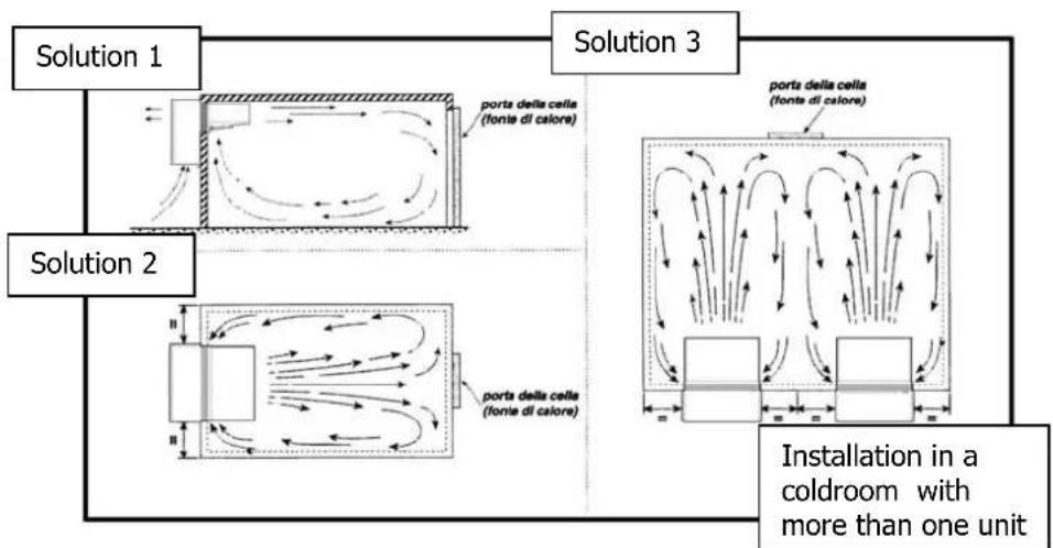
flowchart
graph TD
    A["Solution 1"] --> B["Porta della cella (fonte di calore)"]
    C["Solution 2"] --> D["Porta della cella (fonte di calore)"]
    E["Solution 3"] --> F["Porta della cella (fonte di calore)"]
    G["Installation in a coldroom with more than one unit"]
    style A fill:#f9f,stroke:#333
    style C fill:#f9f,stroke:#333
    style E fill:#f9f,stroke:#333
    style G fill:#f9f,stroke:#333
6.4 Free room
When installing the unit leave enough free room to allow opening, correct use and easy maintenance in safe conditions.
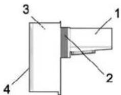
6.5 Installation
Prepare an opening with suitable dimensions in the cold room wall (see picture).
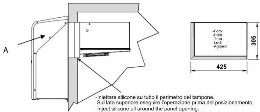
-Inject silicone all around the panel opening. Apply silicone on the upper side before positioning the unit.
| A | B | C | D | E | |||||
| LMD MF075/LF170 705 | 300 305 | 100 420 | 305 425 | 100 10 | |||||
| LMD MF100-120/LF200 695 | 300 305 | 100 420 | 305 725 | 100 10 | |||||
| LMD MF230/LF350 800 | 470 400 | 120 580 | 475 725 | 100 10 | |||||
| LMD MF350/LF500 857 | 470 440 | 120 580 | 480 1130 | 100 18 | |||||
| LMD MF400-600/LF600-750 | 857 500 | 440 120 | 850 510 | 1600 100 22 | |||||
| LMD MF750/LFM000 857 | 570 490 | 120 970 | 580 1640 | 100 22 |
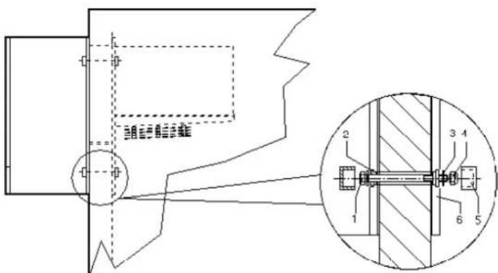
A) Position the unit on the cold room inserting the evaporator section in the opening.
B) Fix the unit using the screws supplied.
C) Fit a drain line to the defrost water drain connection in the lower part of the condensing unit.
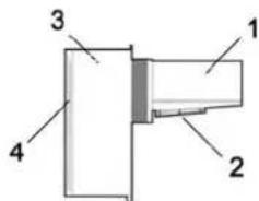
N.B.: Before siting the unit (only for the models LMD MF075/LF170), dismount the front panel A.
(LMD MF350-400-600-750/ LF500-600-750-M00)
6.6 Safety devices
The following mechanical safety devices are supplied:
- Fixed upper and side protections for evaporator and condensing unit, secured by locking screws.
- External fan protections placed on the evaporating and condensing units, secured with screws.
The following electrical safety devices are supplied:
a. Protection of fans (belonging to motors) against high power absorption; with automatic reset.
b. High pressure switch (only for special components) to protect against excessive pressure; with automatic reset.

WARNING
Above devices have been developed to safeguard the operator's safety.
6.7 Cleaning
Clean the unit carefully. Remove any dust, foreign substances and dirt possibly deposited during handling. Use detergents and degreasers.

ATTENTION
Solvents are not allowed.
7 Connecting the unit
ATTENTION
Before connecting the unit make sure that mains voltage and frequency correspond to the values shown in the data plate. Voltage tolerance: +/- 10% compared to nominal value.
7.1 Electric connection
Connect the unit after checking the panel components.
When choosing the protective device take the following into consideration: should the prospective short-circuit current at installation point be higher than 10 KA, install a limiting device which reduces its peak value to 17 KA. Prospective short-circuit current (Ik): current which would flow in case of failure due to negligible impedance, provided that no protective device against overcurrent has been installed on the circuit. Peak value: max value of prospective short-circuit current.

ATTENTION
Connection to the electric line shall be effected applying a suitable safety device (a circuit breaker or a ground fault interrupter) selected by the installer on the basis of the line involved and of the absorption indicated on the unit plate.
If a cold room includes more units, each unit shall be provided with its own safety device.
Connect the unit paying attention to the colours of the supply cable wires:
a) 230V/1/50-60Hz 3 wires Blue = Neutral Yellow/Green = Ground
B r o w n = P
b) 230V/3/50-60Hz 4 wires Grey = Phase Yellow/Green = Ground
B r o w n = P B l a c k = P
c) 400/3/50 Hz 5 wires Blue = Neutral Yellow/Green = Ground
B r o w n = P G r e y = P h B l a c k = P
We advise to install a microswitch (not supplied) on the cold room door which will
- switch on the light in the cold room, stop the unit and
- override the temperature alarm (for about one hour after door closing) every time the door is opened.
The necessary cable is available with the unit. Connect it keeping in mind the following: microswitch closed = door closed.
ATTENTION
Above microswitch is not supplied with the unit. If the microdoor cable is disconnected or damaged, the same conditions will occur as in case of open door and connected microdoor.

WARNING
Any defective electrical part should be replaced by trained personnel exclusively. The electric connection should be effected by qualified personnel.
8 Electric controls
8.1 Control panel
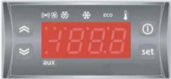
Electronic control unit: it can adjust the cold room temperature and control all the functions of the refrigerating system.
8.2 Pushbuttons and signals on the electronic control panel
| SET(ENTER) |  | Press and releaseIt displays any alarm (if any)It accesses the menu |
| UP |  | Press and releaseIt scrolls the menu itemsIt increases values |
| Down |  | Press and releaseIt scrolls the manu itemsIt decreases values |
| ON/OFF |  | Press for at least 5 secIt activates the ON/OFF function |
Meaning of the led's
A number of points is located on the display whose meaning is described in the following table.
 | Compressor LedFixed on: active compressorFlashing: delay, blocked protection or activation |
 | Defrost Led (De-frosting)Fixed on: active de-frostingFlashing: Mmanual activation or by I.D. |
 | Fan LedFixed on: active fans |
 | Led AlarmFixed on: alarmFlashing: muted alarm |
 | Led AUXFixed on: Cell light ON |
8.3 Instruction to display the parameters
By pressing and releasing the set key you can access the menu. If there are no alarms in progress the "Set" label will be displayed. Through the and keys the menu folders can be scrolled:
- SEt: setting folder
- Pb1: environment probe value folder
- Pb2: end of de-frosting probe value folder
Setting up the Setpoint:
To display the Setpoint value press the set key when the "Set" label is displayed, then press "Set" again. The Setpoint value is displayed.
To change the Setpoint value press within 15 sec, the ↑ and keys. To confirm the change press and wait 15 sec before quitting.
Displaying the probes:
When the labels Pb1 or Pb2 appear, when the set key is pressed the measured values of the associated probe is displayed.
Pb1 displays the cell temperature
Pb2 displays the end of de-frosting temperature.
Starting the manual de-frosting cycle:
To start a de-frosting cycle, press the 🔊 key for at least five seconds.
Cell light activation:
The cell light is switched on when the key is pressed.
ON/OFF function:
When the ON/OFF key is pressed for at least 5 sec. the equipment is set to stand-by and displays OFF. In this configuration the unit is not active. To set the equipment to ON press the key again.
WARNING
The unit is powered even when OFF continues to be displayed on the control unit.
9 Checks, regulations and adjustments
Before turning the unit on, check that:
- locking screws are tight
- electrical connections have been carried out correctly.
In the event that the unit has been opened:
- no tools were left inside
- assembly is correct
- there are no gas leaks
- front cover is secured correctly
9.1 Starting
1) Connect the supply cable to the unit plug: on the panel the light of the "B" switch will turn on indicating supply connection.
2) The unit is now pre-heating. We advise to keep the unit at this stage for at least 2 hours.
3) After pre-heating press the "B" (2) switch to position 1: the unit is now working.
N.B.: Each time mains supply is turned off for more than 24 hours, it is necessary to repeat the pre-heating stage to restart the unit.
ATTENTION
24 hours after starting check evaporator state. If ice has formed, defrost frequency should be increased. In low temperature units the evaporator condition should be checked every week during the first month of operation.
10. Wiring
A wiring diagram, specific for the units of the LMD series, is enclosed with these use and maintenance instructions.
11. Maintenance and repairs
Suitable maintenance is crucial for obtaining longer life, perfect working conditions and high efficiency of the unit as well as for ensuring the safety features provided by the manufacturer.
12 Routine maintenance
Good operation of the unit requires the condenser to be cleaned periodically (frequency of cleaning depends on the environment where the unit is installed).
Turn off the unit and clean it by blowing air from the inside outwards. Should no air jet be available, use a long-haired brush and work on the outside of the condenser.
In case of water-cooled condensers have the unit cleaned by a plumber with special descaling agents.

WARNING
Use safety gloves to protect your hands from possible cuts.

WARNING
Disconnect the unit before working on it.
12.1 Periodical maintenance
Periodically check wear condition of electrical contacts and remote switches; if necessary replace them.
12.2 Service operations to be carried out by qualified technicians or by the manufacturer
Following operations shall be carried out by qualified technicians or by the manufacturer exclusively. Under no circumstances the user is allowed to:
- replace electrical components
• work on the electric equipment - repair mechanical parts
• work on the refrigerating system - work on the control panel, ON/OFF and emergency switches
• work on protection and safety devices.
12.3 Troubleshooting
During operation following troubles may occur:
-
Compressor stops. The unit is equipped with an overtemperature device which stops the compressor every time the max. allowable temperature of motor windings is exceeded. Possible causes are:
-
insufficient ventilation of the room where the unit is installed;
- anomaly in mains voltage;
-
faulty operation of condenser fan.
Device reset is automatic. -
Ice forms on the evaporator preventing air from flowing regularly.
Possible causes are:
- the door is opened too frequently;
- faulty operation of evaporator fan;
- faulty solenoid valve (in models with hot gas defrost);
- faulty defrost heater (in models with electric defrost);
- faulty defrost process. In this case some measures can be taken:
increase defrost termination temperature by some degrees, increase number of defrosts.

ATTENTION
Do not use either hot water or any pointed, cutting, metal objects to remove ice blocks.
-
Display does not light up. Check:
-
if there is power to the unit;
- if mains cable is connected properly;
-
fuses inside the electric panel.
-
Unit does not start operating when pressing ON/OFF key (the display is turned on): check microdoor connection keeping in mind that the switch contact must be closed when the door is closed.
Unsatisfactory efficiency of the unit:
If no defects are found in the unit check that: cold room doors are perfectly tight; there is no cold dispersion; the cold room is used wisely; no unfrozen liquids or foodstuffs are placed in the low temperature room; the evaporator is ice-free.
We recommend installation of the machines far from the doors especially when the cold room is expected to be opened many times a day.

WARNING:
Removal of protections during machine operation is absolutely forbidden. They have been developed to safeguard the operator's safety.
12.4 Alarms
| Label | Failure | Cause | Problem resolution |
| E1 | Environment probe (Pb1) | values outside the operation rangefailed / shortcircuited / open probe | check the type of probe (NTC)check the wiring of probesreplace the probe |
| E2 | End of de-frosting probe (Pb2) | values outside the operation rangefailed / shortcircuited / open probe | check the type of probe (NTC)check the wiring of probesreplace the probe |
| AH1 | Alarm of HIGH ambient temperature | exceeding of the preset temperature (over the maximum preset differential) | check the compressor operation.check of cell (open doors), its seal, introduction of hot product etc. |
| AL1 | Alarm of LOW ambient temperature | exceeding of the preset temperature (over the minimum preset differential) | check the operation of the control unit. |
| OPd Alarm door open | door open | ||
| nPA | High pressure | Each time the pressure switch trips, the buzzer and the red led are activated. If more than 10 trips occur in 1 hour, then the unit is turned off automatically. | Faulty operation of condenser fan.Dirty condenser |
Probe alarms "E1" and "E2" start some seconds after the fault in the related probe; they automatically stop some seconds after the probe restarts normal operation. Check connections before replacing the probe.
Temperature alarms "AH1" and "AL1" automatically stop as soon as the thermostat temperature returns to normal values and when defrost starts.

WARNING
When the high pressure switch cuts off, the unit stops and the alarm led switches on. The alarm reset is automatic. If the pressure switch cuts off 10 times during 1 hour, it will be necessary to switch off and then switch the unit on again.
13 How To Order Spare Parts
When ordering spare parts make reference to the number written on the unit plate.

WARNING
Worn parts should be replaced only by qualified personnel or by the manufacturer.
14 How To Dispose Of The Packing
Wooden, plastic, polystyrene packing shall be disposed of according to the regulations in force in the country where the unit is used.
15 How To Dispose Of The Unit
Do not discharge scrapped components in the environment. They should be disposed of by companies dealing with special waste collection and recovery, according to the regulations in force in the country where the unit is used.

WARNING
Do not discharge the refrigerant in the atmosphere. It companies dealing with special waste collection and recovery.
INDEX
natural_image
Illustration of a forklift and two gas cylinders with upward arrows indicating motion (no text or symbols)
AVERTISSEMENTS
(LMD MF350-400-600-750/ LF500-600-750-M00)

AVERTISSEMENTS
natural_image
Illustration of a forklift and two stacked storage tanks (no text or symbols)HINWEISE

(LMD MF350-400-600-750/ LF500-600-750-M00)

HINWEISE
natural_image
Illustration of a forklift and two gas cylinders with upward arrows indicating motion (no text or symbols)WAARSCHUWING

6.2 Afmetingen
LMD MF075/LF170
Other models
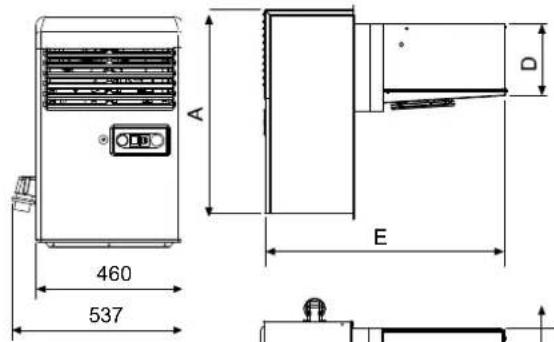
| A | B | C | D | E | |||
| LMD MF100-120/LF200 695 | 305 490 245 | 825 720 | 754 832 | ||||
| LMD MF230/LF350 800 | 400 700 | 385 1100 720 | 754 832 | ||||
| LMD MF350/LF500 857 | 440 700 | 385 1100 1120 | 1128 | 1210 | |||
| LMD MF400-600/LF600-750 | 857 440 | 970 380 | 1410 | 1560 1598 | 1698 | ||
| LMD MF750/LFM000 857 | 490 1090 460 | 1580 1600 | 1638 | 1738 |
F
6.3 Locatie
-Inject silicone all around the panel opening. Apply silicone on the upper side before positioning the unit.