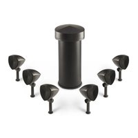
Dymension Outdoor LS-6.1 - Loudspeaker DEFINITIVE TECHNOLOGY - Free user manual and instructions
Find the device manual for free Dymension Outdoor LS-6.1 DEFINITIVE TECHNOLOGY in PDF.


| Product Type | Satellite and subwoofer outdoor speaker system |
| Brand | Definitive Technology |
| Model | Dymension Outdoor LS-6.1 |
| Components | 6 LS-400 satellite speakers, 1 LS-80 subwoofer |
| Satellite speaker type | 2-way (0.75" aluminum oxide dome tweeter, 4" woofer) |
| Subwoofer type | 8" subwoofer |
| Satellite frequency response | 135 Hz to 21 kHz (-3 dB) |
| Subwoofer frequency response | 45 Hz to 105 Hz (-3 dB) |
| Satellite impedance | 32 Ω nominal |
| Subwoofer impedance | 8 Ω per channel (2 channels) |
| Satellite power handling | 50 W |
| Subwoofer power handling | 200 W |
| Satellite sensitivity | 76 dB SPL (2.83 V at 1 m) |
| Subwoofer sensitivity | 84 dB SPL (2.83 V at 1 m) |
| Satellite protection rating | IP56 |
| Subwoofer protection rating | IP54 |
| Satellite cabinet material | PP +30% mineral filling |
| Subwoofer cabinet material | PE |
| Satellite dimensions (without stake) | 146 x 188 x 291 mm (W x H x D) |
| Satellite dimensions (with stake) | 146 x 188 x 498 mm |
| Subwoofer dimensions | 324 x 328 x 665 mm |
| Satellite weight (without stake) | 2 kg |
| Subwoofer weight | 10.3 kg |
| Warranty | 5 years (United States and Canada) |
| Maintenance | Clean with a dry cloth, avoid chemicals |
| Safety | Do not use near water, avoid heat sources |
| Usage | Outdoor, in-ground installation |
Frequently Asked Questions - Dymension Outdoor LS-6.1 DEFINITIVE TECHNOLOGY
User questions about Dymension Outdoor LS-6.1 DEFINITIVE TECHNOLOGY
0 question about this device. Answer the ones you know or ask your own.
Ask a new question about this device
Download the instructions for your Loudspeaker in PDF format for free! Find your manual Dymension Outdoor LS-6.1 - DEFINITIVE TECHNOLOGY and take your electronic device back in hand. On this page are published all the documents necessary for the use of your device. Dymension Outdoor LS-6.1 by DEFINITIVE TECHNOLOGY.
USER MANUAL Dymension Outdoor LS-6.1 DEFINITIVE TECHNOLOGY
IMPORTANT SAFETY INSTRUCTIONS
- Read these instructions.
- Keep these instructions.
- Heed all warnings.
- Follow all instructions.
- Do not use this apparatus near water.
-
Clean only with dry cloth.
-
Do not block any ventilation openings. Install in accordance with the manufacturer's instructions.
-
Do not install near any heat sources such as radiators, heat registers, stoves, or other apparatus (including amplifiers) that produce heat.
-
Protect the power cord from being walked on or pinched particularly at plugs, convenience receptacles, and the point where they exit from the apparatus.
-
Only use attachments/accessories specified by the manufacturer.
-
Use only with the cart, stand, tripod, bracket, or table specified by the manufacturer, or sold with the apparatus. When a cart is used, use caution when moving the cart/apparatus combination to avoid injury from tip-over.

-
Unplug this apparatus during lightning storms or when unused for long periods of time.
-
Refer all servicing to qualified service personnel. Servicing is required when the apparatus has been damaged in any way, such as power-supply cord or plug is damaged, liquid has been spilled or objects have fallen into the apparatus, the apparatus has been exposed to rain or moisture, does not operate normally, or has been dropped.
Notes on Use
- Avoid high temperatures.
- Do not let foreign objects into the unit.
- Do not let insecticides, benzene, and thinner come in contact with the unit.
- Never disassemble or modify the unit in any way.
- Naked flame sources such as lit candles should not be placed on the unit.
- Do not sit or step on unit.
- Do not place unit in standing water.
Sound United, LLC
5541 Fermi Court
Carlsbad, CA 92008, USA
1. Introduction
The Definitive Technology LS-6.1 Landscape System is engineered to deliver superb audio quality and durability in residential and light commercial outdoor audio applications. With proper placement, the included subwoofer and six satellite speakers provide a balanced frequency response with even coverage across the listening environment. An additional pair of LS-400 satellite speakers can be purchased to scale the system for slightly larger listening areas.
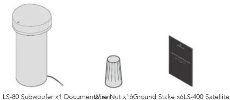
2. Box Contents
Ensure the following items are included in the box.
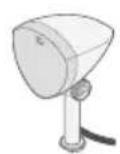
Speaker x6
natural_image
Illustration of three electronic components: a cylindrical device, a conical component, and a screen with a symbol (no text or labels on the devices themselves)3. Planning the Installation
• To achieve the best coverage, place the speakers and subwoofer approximately 5–6' apart.
- Place the subwoofer as close to the center of the satellites as possible for optimal frequency balance between the subwoofer and satellites (see the example layout in Figure 1).
- For applications that require more bass, place the subwoofer near an acoustically reflective surface, such as a wall or barrier, to reinforce the low frequencies.
- In some applications, better performance may be achieved by placing the subwoofer closer to the primary listening position.
- If possible, try placing the speakers and subwoofer in locations that minimize volume peaks and nulls throughout the outdoor listening area.
- To avoid potential damage from landscapers, be mindful of where you mount the subwoofer and speakers. Locate the subwoofer in an area that will not flood with standing water.
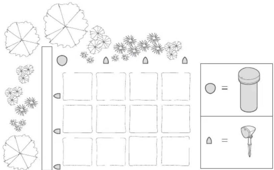
Figure 1
4. Choosing the Speaker Wire Type
We recommend using color-coded, 4-conductor direct-burial speaker wire, such as '14/4' (14-gauge, 4-conductor). Refer to the wiring chart below to determine the minimum required wire gauge for a given distance.
Wire Gauge Distance
16 AWG Up to 150' (45 meters)
14 AWG Up to 250' (80 meters)
NOTE: Use only direct-burial wire to prevent corrosion and prolong signal integrity. Alternatively, low-voltage lighting wire can be used, but note that it is only available as a 2-conductor wire. If using a 2-conductor wire, run two pairs of wires: one for the left amplifier channel/speakers and one for the right. The included wire nuts can accommodate a wire gauge of up to 14 AWG.
5. Preparing for Speaker Installation
Recommended Items
- Shovel
- Wire stripper that accommodates up to 14-gauge wire
• Round cable stripper or utility knife - Speaker wire spool with sufficient speaker wire for the planned installation
- Wire/zip ties
- Electrical tape
- Rubber mallet
- Measuring tape
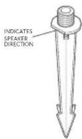
Figure 2
Getting Started
- Set the satellite speakers and subwoofer in the approximate mounting locations determined in section 3 "Planning the Installation" on the previous page.
- Using a rubber mallet, carefully pound the included satellite ground stakes into the ground at the predetermined mounting locations. Note the flat indicator on the stake and ensure this indicator faces the desired speaker direction (see Figure 2).
- Screw the satellite speakers into the mounted ground stakes, ensuring they are pointed in the intended direction.
- Dig a trench between the speaker locations for running the speaker wires. Be sure to follow local codes for trenching limitations.
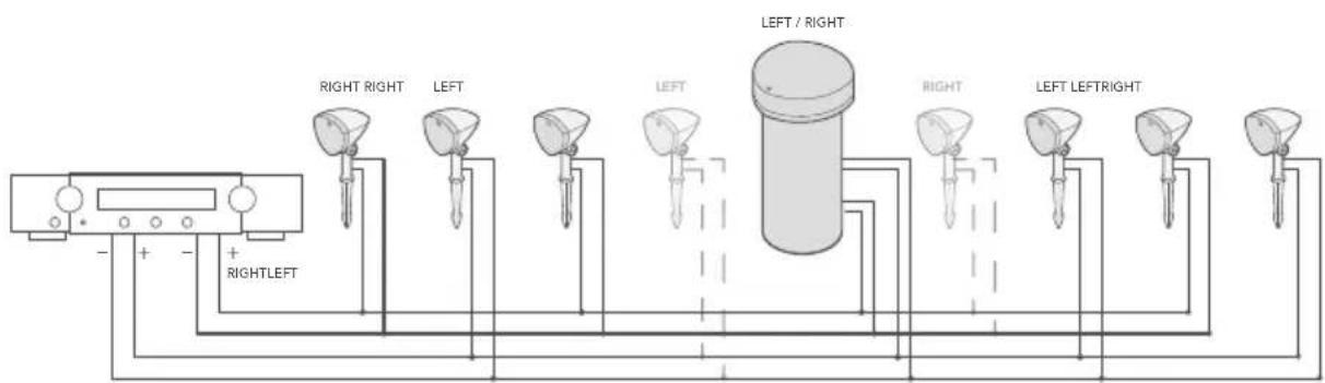
- Run the speaker wire through the trench as described in the wiring instructions in section 6 "Installing the Satellite Speakers" on the next page. We recommend leaving 14-16" of excess wire per speaker so that the wire doesn't kink or pull taut when covering the wire with dirt in the trench. Figure 3 shows the wiring of a complete system using a stereo amplifier. Note that an additional pair of satellites can be purchased and installed for slightly larger applications.
flowchart
graph TD
    A["Device"] -->|+| B["Right Left"]
    A -->|-| C["Right Right"]
    B --> D["Left"]
    C --> E["Left"]
    D --> F["Central Column"]
    E --> F
    F --> G["Left / Right"]
    F --> H["Right"]
    F --> I["Left Left Right"]
    F --> J["Right"]
    F --> K["Left Left"]
    style F fill:#f9f,stroke:#333,stroke-width:2px
Figure 3
IMPORTANT: To prevent potential damage to the amplifier caused by short circuiting of the speaker wires, do not connect the speaker wires to the amplifier until after all speaker connections are made and secure.
IMPORTANT: Connect the subwoofer only as shown. Do not connect the two subwoofer channels in parallel, as doing so would cause the impedance to drop too low and potentially damage the amplifier/receiver.
| Satellites Per Amp Channel | Subwoofer Connected | Channel Load Impedance |
| 1 No 32Ω | ||
| 2 No 16Ω | ||
| 3 No 11Ω | ||
| 4 No 8Ω |
| Satellites Per Amp Channel | Subwoofer Connected | Channel Load Impedance |
| 1 Yes 6.4Ω | ||
| 2 Yes 5.4Ω | ||
| 3 Yes 4.6Ω | ||
| 4 Yes 4Ω |
Impedance per amplifier channel with speakers/subwoofer connected in parallel
6. Installing the Satellite Speakers
IMPORTANT: Ensure the speaker load presented to the amplifier is within its published specifications. Do not connect more than four satellite speakers to an amp channel. Miswiring may result in an unacceptable load, which might damage the amplifier.
Using 4-Conductor Direct-Burial Wire
- Unwind the 4-conductor wire spool towards the amplifier from the furthest speaker, leaving the wire attached to the spool at the amplifier end. Do not connect the wires to the amplifier at this time.
-
Starting at the speaker furthest from the amplifier, strip 3/4" of insulation on the cut end of the burial wires for the appropriate amp channel according to the tables below, then strip insulation from the ends of the corresponding speaker's pigtail. Wrap any unused wires in electrical tape to protect them from moisture and short-circuiting (see Figure 4).
-
Connect the burial cable to the speaker pigtail using a wire tie (see Figure 4).
-
Twist to combine all the positive (+) wires together and combine all the negative (-) wires together according to the tables below.
-
Twist the provided silicone-filled wire nuts onto the combined positive wires and onto the combined negative wires, ensuring that no copper is exposed. Wrap each wire nut connection in electrical tape to protect it from moisture.
-
Leave 14-16" of excess wire at the speaker so that the wire doesn't kink or pull taut during burial, then move to the next speaker along the cable.
-
At the next speaker, use a round cable stripper or utility knife to remove 8" of the outside wire jacket, exposing the four insulated wires.
-
Cut the correct two wires for the left or right speaker (see the tables below) and strip 3/4" of insulation on the exposed ends of the burial wires, then strip 3/4" insulation from the ends of the corresponding speaker's pigtail (see Figure 5).
-
Create a loop of approximately 10", and use a wire tie to hold the wire loop and speaker pigtail in place to provide strain relief (see Figure 5).
-
Repeat steps 4-6 then continue for each remaining satellite along the cable. For subwoofer installation, see section 7 "Installing the Subwoofer."
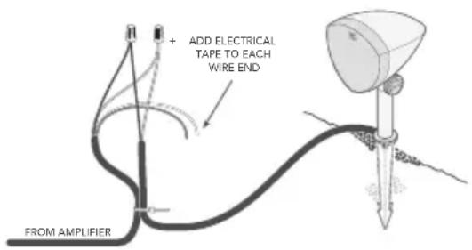
Figure 4
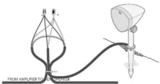
Figure 5
Polarity Burial Wire Speaker Pigtail
- White Red
- Green Black
Left Amp Channel
Polarity Burial Wire Speaker Pigtail
- Red Red
- Black Black
Right Amp Channel
Using 2-Conductor Wire or Low-Voltage Lighting Wire
- Unwind the 2-conductor wire spool towards the amplifier from the furthest speaker, leaving the wire attached to the spool at the amplifier end. Do not connect the wires to the amplifier at this time.
-
Starting at the speaker furthest from the amplifier, strip 3/4" of insulation on the cut end of the burial wires for the appropriate amp channel according to the tables below, then strip insulation from the ends of the corresponding speaker's pigtail (see Figure 6).
-
Connect the burial cable to the speaker pigtail using a wire tie (see Figure 6).
-
Twist to combine all the positive (+) wires together and combine all the negative (-) wires together according to the tables below.
-
Twist the provided silicone-filled wire nuts onto the combined positive wires and onto the combined negative wires, ensuring that no copper is exposed. Wrap each wire nut connection in electrical tape to protect it from moisture.
-
Leave 14-16" of excess wire at the speaker so that the wire doesn't kink or pull taut during burial, then move to the next speaker of the same channel (left or right) along the cable.
-
At the next speaker, use a round cable stripper or utility knife to remove 8" of the outside wire jacket, exposing the two insulated wires.
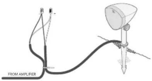
Figure 6
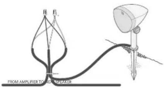
Figure 7
-
Cut the two wires for the left or right speaker (see the tables below) and strip 3/4" of insulation on the exposed ends of the burial wires, then strip 3/4" insulation from the ends of the corresponding speaker's pigtail (see Figure 7).
-
Create a loop of approximately 10", and use a wire tie to hold the wire loop and speaker pigtail in place to provide strain relief (see Figure 7).
-
Repeat steps 4-6 for each remaining satellite speaker along the cable. For subwoofer installation, see section 7 "Installing the Subwoofer" on the next page.
-
Repeat steps 1-10 for the other amp channel.
Polarity Burial Wire Line 1 Speaker Pigtail
+ Positive Red
- Negative Black
Left Amp Channel
Polarity Burial Wire Line 2 Speaker Pigtail
+ Positive Red
- Negative Black
Right Amp Channel
7. Installing the Subwoofer
The subwoofer can be connected anywhere in the daisy chain. However, positioning the subwoofer in the middle of the daisy chain with equal spacing between the speakers will typically provide a more balanced frequency response across the listening area.
- As with the satellite speaker installation, create a loop approximately 10" in length, pulling the wire from the spool side. Leave 14-16" of excess wire so that the wire doesn't kink or pull taut when covering the wire with dirt in the trench. Use a wire tie to hold the wire loop in place and provide strain relief (see Figure 8).
- Twist to combine the positive wires for the right channel together, followed by the negative wires for the right channel. Repeat for the left channel wires. See the tables below for subwoofer connection reference. Do not connect the subwoofer left and right channels together in parallel.
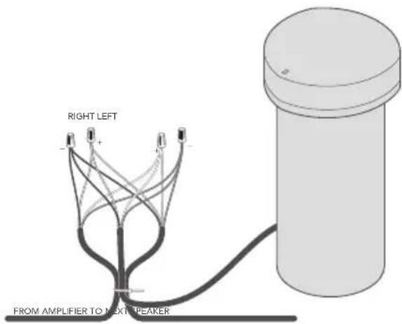
Figure 8
Polarity Burial Wire Subwoofer Coil 2
+ White White
- Green Green
Left Amp Channel
Polarity Burial Wire Subwoofer Coil 1
+ Red Red
- Black Black
Right Amp Channel
IMPORTANT: The positive and negative wires must be connected correctly for both subwoofer channels (left and right). If either channel is connected in reverse, the subwoofer will not pass audio due to phase cancellation.
Bury the Subwoofer
Dig a hole with a 16" diameter and a depth of 16". Place the subwoofer in the hole and ensure there is about 6" of exposed subwoofer enclosure from the ground to the bottom edge of the subwoofer canopy (see Figure 9). It is recommended to test the system as described in section 8 "Finalizing the Installation" below before filling in the hole.
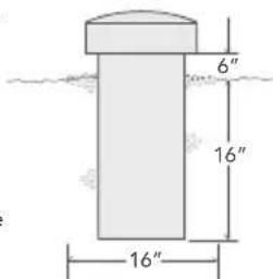
Figure 9
8. Finalizing the Installation
- With all the satellites and subwoofer properly connected, ensure the amplifier/receiver is powered off. Connect the left/right speaker wires to the matching positive (+) and negative (-) terminals on the amplifier/receiver (see the amp wiring diagram in Figure 3).
- Adjust the vertical angle of the LS-400 speakers: Hold the speaker's head while loosening the adjustment knob with the other hand. Adjust the vertical angle so that the speaker's head points toward the listening area and then tighten the adjustment knob. Repeat for each LS-400 in the system.
- Power on the sound source and amplifier/receiver, then test the system with music.
- Once it is confirmed that all the satellites and subwoofer are operating correctly, fill in the hole around the subwoofer and wire trench to complete the installation.

For support, FAQs or more information about these products, please visit www.definitivetechnology.com or scan the QR code.
LS-400 Specifications
Speaker Type / Electrical
| Tweeter 0.75" aluminum oxide dome |
| Woofer 4" midrange driver |
| Frequency Response (-3 dB) 135 Hz to 21 kHz |
| Impedance 32Ω nominal |
| Power Handling 50W |
| Sensitivity (2.83 V @ 1 m) 76 dB SPL |
Physical
| Enclosure Material PP +30% mineral fill | |
| Rating IP56 rated for outdoor use | |
| Product Dimensions (W x D x H) | 146 mm (5.75") x 188 mm (7.40") x 291 mm (11.46") (without ground stake) |
| 146 mm (5.75") x 188 mm (7.40") x 498 mm (19.61") (with ground stake) | |
| Product Weight (Each) | 2 kg (4.4 lbs) (without ground stake) |
| 2.1 kg (4.6 lbs) (with ground stake) | |
Specifications are subject to change without notice.
LS-80 Specifications
Speaker Type / Electrical
| Woofer 8" |
| Frequency Response (-3 dB) 45 Hz to 105 Hz |
| Impedance 8Ω nominal per channel x 2 channels |
| Power Handling 200W |
| Sensitivity (2.83 V @ 1 m) 84 dB SPL |
Physical
| Enclosure Material PE | |
| Rating IP54 rated for outdoor use | |
| Product Dimensions (W x D x H) | 324 mm (12.76") x 328 mm (12.91") x 665 mm (26.18") |
| Product Weight | 10.3 kg (22.8 lbs) |
Specifications are subject to change without notice.
Limited 5-Year Warranty (United States and Canada)
Definitive Technology, LLC (herein "Definitive") warrants to the original purchaser only that this Definitive Loudspeaker Product (the "Product") will be free from defects in materials and workmanship for a limited period of five (5) years from the date of original retail purchase from a Definitive Authorized Dealer. However, this Warranty will automatically terminate prior to the expiration of the five (5) years if the original retail purchaser sells or otherwise transfers the Product to any other party. The original retail purchaser shall hereinafter be referred to as "you." To allow Definitive to offer the best possible warranty service, please visit the website on the Product Registration Card(s) and fill out the form within ten (10) days of the date of purchase.
Defective Products must be shipped, together with proof of purchase, prepaid insured to the Definitive Authorized Dealer from whom you purchased the Product, or an authorized service center. Products must be shipped in the original shipping container or its equivalent; in any case the risk of loss or damage in transit is to be borne by you. If upon examination at the Factory or Definitive Authorized Dealer it is determined that the Product was defective in materials or workmanship at any time during this Warranty period, Definitive or the Definitive Authorized Dealer will, at its option, repair or replace this Product at no additional charge, except as set forth below. All replaced parts and Products become the property of Definitive. Products replaced or repaired under this warranty will be returned to you, within a reasonable time, freight prepaid.
This warranty does not include service or parts to repair damage caused by accident, disaster, misuse, abuse, negligence, inadequate packing or shipping procedures, commercial use, voltage inputs in excess of the rated maximum of the unit, cosmetic appearance of cabinetry not directly attributable to defect in materials or workmanship, or service, repair, or modification of the Product which has not been authorized or approved by Definitive. This warranty shall terminate if the Serial number on the Product has been removed, tampered with or defaced. This warranty is in lieu of all other expressed Warranties. If this Product is defective in materials or workmanship as warranted above, your sole remedy shall be repair or replacement as provided above. In no event will Definitive be liable to you for any incidental, special, or consequential damages arising out of the use or inability to use the Product, even if Definitive or a Definitive Authorized Dealer has been advised of the possibility of such damages, or for any claim by any other party. Some states or provinces do not allow the exclusion or limitation of consequential damages, so the above limitation and exclusion may not apply to you. All implied warranties on this Product are limited to the duration of this expressed Warranty. Some states or provinces do not allow limitation on how long an implied Warranty lasts, so the above limitations may not apply to you. This Warranty gives you specific legal rights, and you also may have other rights which vary from state to state or province to province. Definitive has no liability for acts of third parties. Definitive's liability, whether based on contract, tort, or any other theory, shall not exceed the purchase price of the Product for which a claim has been made. For U.S. warranty claims, the consumer agrees and consents that all disputes shall be resolved in accordance with California laws in San Diego County, California. Definitive reserves the right to modify this warranty statement at any time.
This Warranty applies only to Products purchased in the United States of America, its possessions, and U.S. and NATO armed forces exchanges and Canada, except Quebec. Residents of Quebec are governed by that province's consumer protection legislation. The Warranty terms and conditions applicable to Products purchased in other countries are available from the Definitive Authorized Distributors in such countries. Please see the warranty guide specific to Products purchased in countries or territories not referenced herein.
natural_image
Simple line drawing of a cylindrical object with a circular top and a small cable at the bottom (no text or symbols)Figure 1
natural_image
Simple line drawing of a cylindrical object with a circular top and a small cable at the bottom (no text or symbols)Subwoofer LS-80 x1
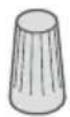
Figura 1
natural_image
Simple 3D illustration of a cylindrical object with a lid and a cable, no text or symbols present.LS-80 低音炮 x1

接线螺母×16

文档
3. 规划安装
图1
4. 选择扬声器线类型
natural_image
Empty rectangular frame with dashed and solid lines, no text or symbols present
- IMPORTANT SAFETY INSTRUCTIONS
- Notes on Use
- Introduction
- Box Contents
- Planning the Installation
- Choosing the Speaker Wire Type
- Wire Gauge Distance
- Preparing for Speaker Installation
- Recommended Items
- Getting Started
- Installing the Satellite Speakers
- Using 4-Conductor Direct-Burial Wire
- Polarity Burial Wire Speaker Pigtail
- Using 2-Conductor Wire or Low-Voltage Lighting Wire
- Polarity Burial Wire Line 1 Speaker Pigtail
- Polarity Burial Wire Line 2 Speaker Pigtail
- Installing the Subwoofer
- Polarity Burial Wire Subwoofer Coil 2
- Polarity Burial Wire Subwoofer Coil 1
- Bury the Subwoofer
- Finalizing the Installation
- LS-400 Specifications
- LS-80 Specifications
- Limited 5-Year Warranty (United States and Canada)
- 规划安装
- 选择扬声器线类型
Brand : DEFINITIVE TECHNOLOGY
Model : Dymension Outdoor LS-6.1
Category : Loudspeaker