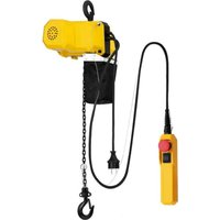
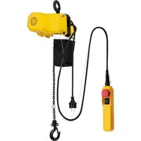
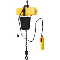
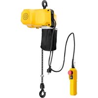
SBS-ECH-150/6 - Electric hoist STEINBERG - Free user manual and instructions
Find the device manual for free SBS-ECH-150/6 STEINBERG in PDF.


| Product Type | Electric Chain Hoist |
| Brand | Steinberg |
| Model | SBS-ECH-150/6 |
| Dimensions (L x D x H) | 225 x 180 x 215 mm |
| Weight | 9 kg |
| Supply Voltage | 230 V~ / 50 Hz |
| Rated Current | 1 A |
| Rated Power | 205 W |
| Maximum Load | 150 kg |
| Lifting Speed | 4 m/min |
| Lifting Height | 5 m |
| IP Protection Class | IP54 |
| Duty Cycle | ED 25 % (2.5 min of operation / 7.5 min of rest) |
| Insulation Class | B |
| Ambient Operating Temperature | 0 °C to 40 °C |
| Chain Tensile Strength | ≥ 900 N/mm² |
| Chain Link Diameter | 4 mm |
| Chain Material | High-strength steel |
| Suspension Hook | Yes, with safety latch |
| Wired Remote Control | Yes, with emergency stop and up/down buttons |
| Safety Devices | Emergency stop, upper and lower limit switches, overload protection, mechanical brake |
| Usage | Indoor only, vertical lifting of free loads |
| Maintenance | Chain lubrication every 200 cycles, regular inspection of parts |
Frequently Asked Questions - SBS-ECH-150/6 STEINBERG
User questions about SBS-ECH-150/6 STEINBERG
0 question about this device. Answer the ones you know or ask your own.
Ask a new question about this device
Download the instructions for your Electric hoist in PDF format for free! Find your manual SBS-ECH-150/6 - STEINBERG and take your electronic device back in hand. On this page are published all the documents necessary for the use of your device. SBS-ECH-150/6 by STEINBERG.
USER MANUAL SBS-ECH-150/6 STEINBERG
SBS-ECH-300/3, SBS-ECH-150/6, SBS-ECH-150/3
natural_image
Yellow industrial device with red circular button and black base, showing bidirectional arrow indicator (no text or symbols)natural_image
Simple line drawing of a mechanical device with no text or symbolsnatural_image
Technical line drawing of a mechanical device with internal components and mounting holes (no text or symbols)SBS-ECH-300/3 Stückliste
This User Manual has been translated for your convenience using machine translation. Reasonable efforts have been made to provide an accurate translation; however, no automated translation is perfect nor is it intended to replace human translators. The official User Manual is the English version. Any discrepancies or differences created in the translation are not binding and have no legal effect for compliance or enforcement purposes. If any questions arise related to the accuracy of the information contained in the User Manual, please refer to the English version of those contents which is the official version.
Technical data
| Parameter description Parameter value | ||
| Product name | ELECTRIC CHAIN HOIST | |
| Model | SBS-ECH-500/3 | SBS-ECH-300/3 |
| Supply voltage [V~] / Frequency [Hz] | 230~/ 50 230~/ 50 | |
| Electricity [A] | 2,4 | 1.7 |
| Rated power [W]. | 540 | 410 |
| Maximum working load [kg] | 500 | 300 |
| Lifting speed [m/min] | 2.8 | 3 |
| Insulation class | B | B |
| IP code | IP54 | IP54 |
| Work cycle | ED 25% | ED 25% |
| Transmission ratio | 137:1 | 119:1 |
| Ambient temperature during device operation [°C] | 0-40 0-40 | |
| Hoist class | A2 | A2 |
| Lifting height [m] | 5 | 5 |
| Tensile strength [N/mm2] | ≥900 | ≥900 |
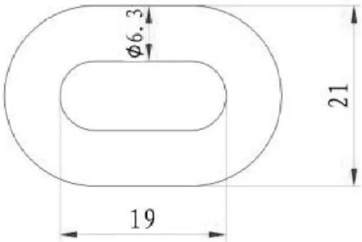
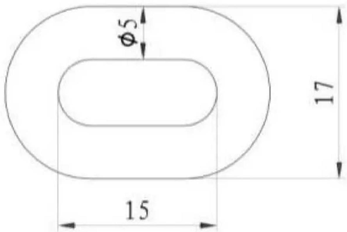
| Cross section diameter of a chain link [mm] | 6.3 5 | |
| Dimensions [width x depth x height; mm] | 380x175x300 285x2 | 20x260 |
| Weight [kg] | 18.50 | 14 |
* The work cycle tells you how long the machine can run in a 10-minute period. A 25% cycle means that the machine can run for 2 minutes and 30 seconds, then it should cool down in idle time for 7 minutes 30 seconds.
| Parameter description Parameter value | ||
| Product name | ELECTRIC CHAIN HOIST | |
| Model | SBS-ECH-150/6 | SBS-ECH-150/3 |
| Supply voltage [V~] / Frequency [Hz] | 230~/ 50 230~/ 50 | |
| Electricity [A] | 1 | 1 |
| Rated power [W]. | 205 | 205 |
| Maximum working load [kg] | 150 | 150 |
| Lifting speed [m/min] | 4 | 2.3 |
| Insulation class | B | B |
| IP code | IP54 | IP54 |
| Work cycle* | ED 25% | ED 25% |
| Transmission ratio | 124:1 | 124:1 |
| Ambient temperature during device operation [°C] | 0-40 0-40 | |
| Hoist class | A2 | A2 |
| Lifting height [m] | 5 | 5 |
| Tensile strength [N/mm ^2 ] | ≥900 | ≥900 |
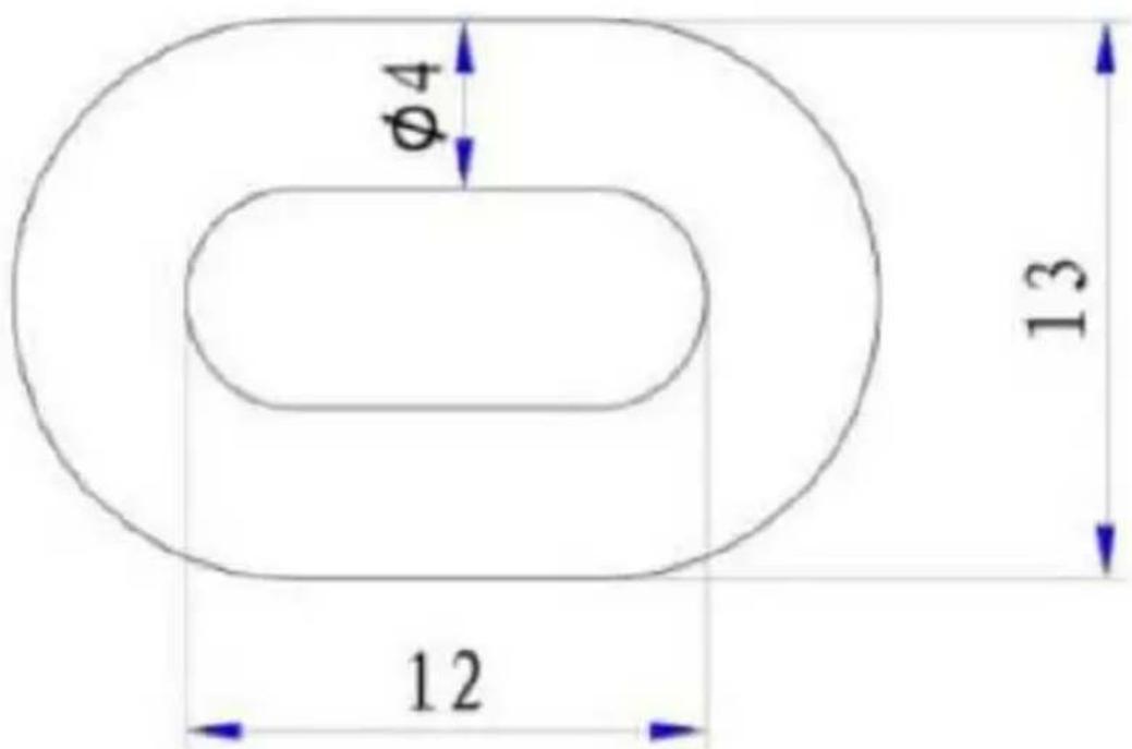
| Cross section diameter of a chain link [mm] | 4 4 | |
| Dimensions [width x depth x height; mm] | 225x180x215 225x180x215 | |
| Weight [kg] | 9 | 8 |
1. General Description
This manual is intended to assist you for safe and reliable use. The product is designed and manufactured strictly according to technical specifications using the latest technology and components and maintaining the highest quality standards.
CAREFULLY READ AND UNDERSTAND THIS MANUAL BEFORE STARTING THE WORK.
To ensure long and reliable operation of the device, make sure to operate and maintain it properly in accordance with the guidelines in this instruction manual. The technical data and specifications in this manual are up-to-date. The manufacturer reserves the right to make changes in order to improve the quality. Taking the technical progress and the possibility of reducing noise into account, the unit is designed and built in such a way so that risks resulting from noise emissions are reduced to the lowest possible level.
Explanation of symbols
| CE | The product complies with applicable safety standards. |
 | Read the manual before use. |
 | Recyclable product. |
 | CAUTION! or WARNING! or REMEMBER! describing a given situation (general warning sign). |
 | Wear ear protection. Exposure to noise may cause hearing loss. |
 | Wear protective head gear. |
 | Wear protective footwear. |
 | CAUTION! Risk of electric shock! |
 | CAUTION! Spinning elements! |
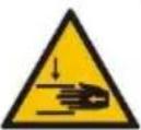 | CAUTION! Danger of crushing your hand!! |
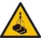 | CAUTION! Hanging weight! |
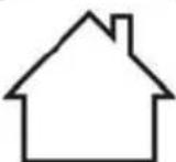 | For indoor use only. |
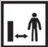 | CAUTION! Ensure that bystanders are a safe distance from the work area. |

CAUTION! The figures in this manual are illustrative only and may vary in some details from the actual appearance of the product.
2. Safety of use

CAUTION! Read all safety warnings and instructions. Failure to follow the warnings and instructions may result in electric shock, fire and/or serious injury or death.
The term "device" or "product" in the warnings and in the description of the manual refers to ELECTRIC CHAIN HOIST.
2.1. Electrical safety
a) The plug of this device must fit into the outlet. Do not modify the plug in any way. Original plugs and matching outlets reduce the risk of electric shock.
b) Avoid touching grounded parts, such as pipes, heaters, ovens, and refrigerators. There is an increased risk of electric shock if your body is grounded and touches the device while exposed to direct rain, wet pavement, or while working in a damp environment. If water enters the device, there is an increased risk of damage to the unit and electric shock.
c) Do not touch the device with wet or damp hands.
d) Do not use the cord in an unintended manner. Never use it to carry the device or to pull the plug out of the socket. Keep the cord away from heat sources, oil, sharp edges or moving parts. Damaged or tangled cords increase the risk of electric shock.
e) If you cannot avoid using the product in a wet environment, use a residual current device (RCD) to connect it to electrical mains. Using an RCD reduces the risk of electric shock.
f) Do not use the device if the power cord is damaged or shows signs of wear. A damaged power cord should be replaced by a qualified electrician or the manufacturer's service department.
g) To avoid electric shock, do not immerse the cable, plug, or the device itself in water or other liquid. Do not use the appliance on wet surfaces.
h) CAUTION – DANGER TO LIFE! When cleaning or using the appliance, never immerse it in water or other liquids.
i) Do not use the appliance in rooms with very high humidity / in the immediate vicinity of water tanks!
j) The electrical outlet to which the unit will be connected must have a grounding wire.
k) The electrical system to which the unit is connected should be equipped with a 10 A fuse or a 10 A overcurrent circuit breaker.
2.2. Safety in the workplace
a) Keep the work area tidy and well lit. Disorder or poor lighting can lead to accidents. Be foresighted, watch what you are doing and use common sense when using the unit.
b) Do not use the unit in an explosive area, for example in the presence of flammable liquids, gases or dust.
c) If you find any damage or irregularities in the operation of the product, immediately turn it off and report it to an authorized person.
d) If in doubt as to whether the device is working, contact the manufacturer's technical service.
e) Repairs to the device may only be carried out by the manufacturer's service. Do not attempt to repair the product on your own!
f) In case of open flames or fire, use only dry powder or snow (CO2) fire extinguishers to extinguish the live equipment.
g) No children or unauthorized persons are allowed in the work area. (Inattention may result in loss of control of the unit.)
h) Keep these instructions for use for future reference. If the product is to be handed over to a third party, hand it over with this user manual.
i) Keep packaging components and small installation parts out of the reach of children.
j) Keep the device away from children and animals.
k) When using this product together with other devices, also follow the other instructions for use.

Remember! Keep children and other bystanders safe while operating the equipment.
2.3. Personal safety
a) Do not operate this device if you are tired, ill or under the influence of alcohol, drugs or medication that could impair your ability to operate the device.
b) The unit may be operated by persons who are physically fit, capable of operating it and appropriately trained, and who have read this instruction manual and have been trained in occupational safety and health.
c) The machine is not intended to be used by persons (including children) with reduced mental, sensory or intellectual functions or persons who lack experience and/or knowledge unless they are supervised or have been instructed by a person responsible for their safety on how to operate the machine.
d) Use caution and common sense when operating this device. A moment's inattention during operation may result in serious personal injury.
e) Use personal protective equipment as required when operating the unit as specified in Section 1 of the explanation of symbols. The use of appropriate, approved personal protective equipment reduces the risk of injury.
f) To prevent accidental start-up, make sure the switch is in the off position before connecting to a power source.
g) Do not overestimate your capabilities. Maintain body balance and equilibrium at all times during operation. This allows for better control of the machine in unexpected situations.
h) Do not wear loose clothing or jewelry. Keep hair, clothing, and gloves away from moving parts. Loose clothing, jewelry, or long hair can be caught in moving parts.
i) Before switching the unit on, remove any regulating tools or keys. Any tools or keys left in the rotating part of the unit may cause injury.
j) The product is not a toy. Children should be watched to ensure that they do not play with the appliance.
2.4. Safe use of the device
a) Do not overload the device. Use tools that are suitable for the application. A correctly selected product will do a better and safer job for which it was designed.
b) Do not use the device if the ON/OFF switch does not function properly (does not turn on and off). Units that cannot be controlled by the switch are unsafe, cannot operate, and must be repaired.
c) Disconnect the device from the power supply before adjusting, cleaning, or servicing. This precaution reduces the risk of accidental start-up.
d) Keep unused product out of the reach of children and anyone unfamiliar with the device or this manual. Products are dangerous when used by inexperienced users.
e) Keep the product in good working order. Check before each use for general damage or damage to moving parts (cracks in parts and components or any other condition that may affect the safe operation of the device). If damaged, have the device repaired before use.
f) Keep the product out of the reach of children.
g) Repairs and maintenance should be carried out by qualified personnel using only original spare parts. This will ensure the safety of use.
h) To ensure the designed operational integrity of the device, do not remove factory-installed covers or loosen screws.
i) When transporting or moving the device from storage to the place of use, observe the health and safety rules for manual handling applicable in the country where the device is used.
j) Avoid situations in which the device stops under heavy loads during operation. This can cause overheating of the drive elements and consequent damage to the equipment.
k) Do not touch any moving parts or accessories unless the device is unplugged.
I) Clean the device regularly to prevent permanent dirt build-up.
m) The product is not a toy. Cleaning and maintenance must not be performed by children without adult supervision.
n) Do not tamper with the device to alter its performance or design.
o) Keep the unit away from sources of fire and heat.
p) Do not block the ventilation openings of the unit!
q) Using the unit to carry weights exceeding its maximum load is forbidden.
r) Do not allow people or animals to stand under suspended loads.
s) Transporting the load by means of the unit over people or animals is prohibited.
t) Transporting people or animals by means of this unit is prohibited.
u) When transporting with the unit, avoid shocks, impacts and sudden changes in speed. This will reduce the risk of the load falling from a height.
v) Before suspending the load, always ensure that the space in which it will be transported is clear of obstructions.
w) Bystanders should be warned of the operation of the equipment and should stay at a safe distance from the load.
x) Always pay close attention to the load.
y) Do not leave suspended loads unattended.
z) Avoid rocking the load.
aa) Do not perform mechanical or similar work (welding, cutting, etc.) on suspended loads.
bb) If the load falls, there is a risk of injury or death.
cc) Do not walk or stand under suspended loads (or in their immediate vicinity).
dd) When using the machine, it is forbidden to pull the chain in any direction other than along the track. Pulling sideways may damage the device.
ee) Do not use excessive force or jerk the cable if resistance is encountered.
ff) Avoid switching on/off sequences at very short intervals.
gg) Make sure that the equipment moves in the direction specified by the controls.
hh) Disconnect the unit from the power supply when not in use.
ii) Do not move loads that are pinned to the ground or blocked by other objects.
jj) Loads must be lifted off the ground at the slowest possible speed.
kk) The permissible load is constant and does not depend on the position in which the load is placed.
II) The device is not designed for continuous operation. Observe the operating cycle of the device.
mm) If the equipment is used in noisy environments, the operator should wear hearing protection.
nn) The A-weighted sound pressure level at the operator's station is less than 78 dB.
oo) The ambient temperature in the operating area should be between 0-40°C.
pp) Always make sure that the load is properly and securely attached to the hook.
qq) Always keep a safe distance from the load and chain.
rr) Do not use limit switches as routine stop items. They are emergency devices only.
ss) Do not drag loads on the ground.
tt) Always keep a safe distance from the load and chain.
uu) Do not use the machine with a twisted, tangled, damaged or worn chain.
vv) Do not lift the load until it is in a central position under the machine.
ww) It is forbidden to extend or repair the chain. A damaged chain must be replaced with a new one at the manufacturer's service facility.
xx) Protect the machine and chain from welding spatter or other harmful contaminants.
yy) Do not work with the machine if the chain cannot form a straight line from the machine body to the hook attached to the load.
zz) Do not use the chain as a sling and do not wrap the chain around the load.
aaa) Do not put any strain on the tip of the hook or the hook latch.
bbb) Do not operate the chain beyond its movement limits.
ccc) The load must be balanced so that it does not tilt during transport and does not fall out of its mount.
ddd) Regularly check that the limit switches of the device are working properly.
eee) Before each lifting operation, check the operation of the brake by applying tension to the chain.
fff) The machine must be inspected regularly and damaged or worn parts must be replaced by an authorized service center.

CAUTION! Although the product has been designed to be safe and has adequate safeguards and despite the additional safety features provided to the user, there is still a slight risk of accident or injury when handling the product. Caution and common sense are advised when using the product.
3. Instructions for use
The machine is intended solely for the vertical lifting and lowering of loose loads in the workplace. The lifting weight of the load must not exceed the given permissible load capacity. The machine can be used in factories, farms, construction sites, for the assembly of equipment and for loading and unloading of goods. Using the machine in corrosive environments and environments with an explosive atmosphere is forbidden.
The user is responsible for any damage resulting from misuse.
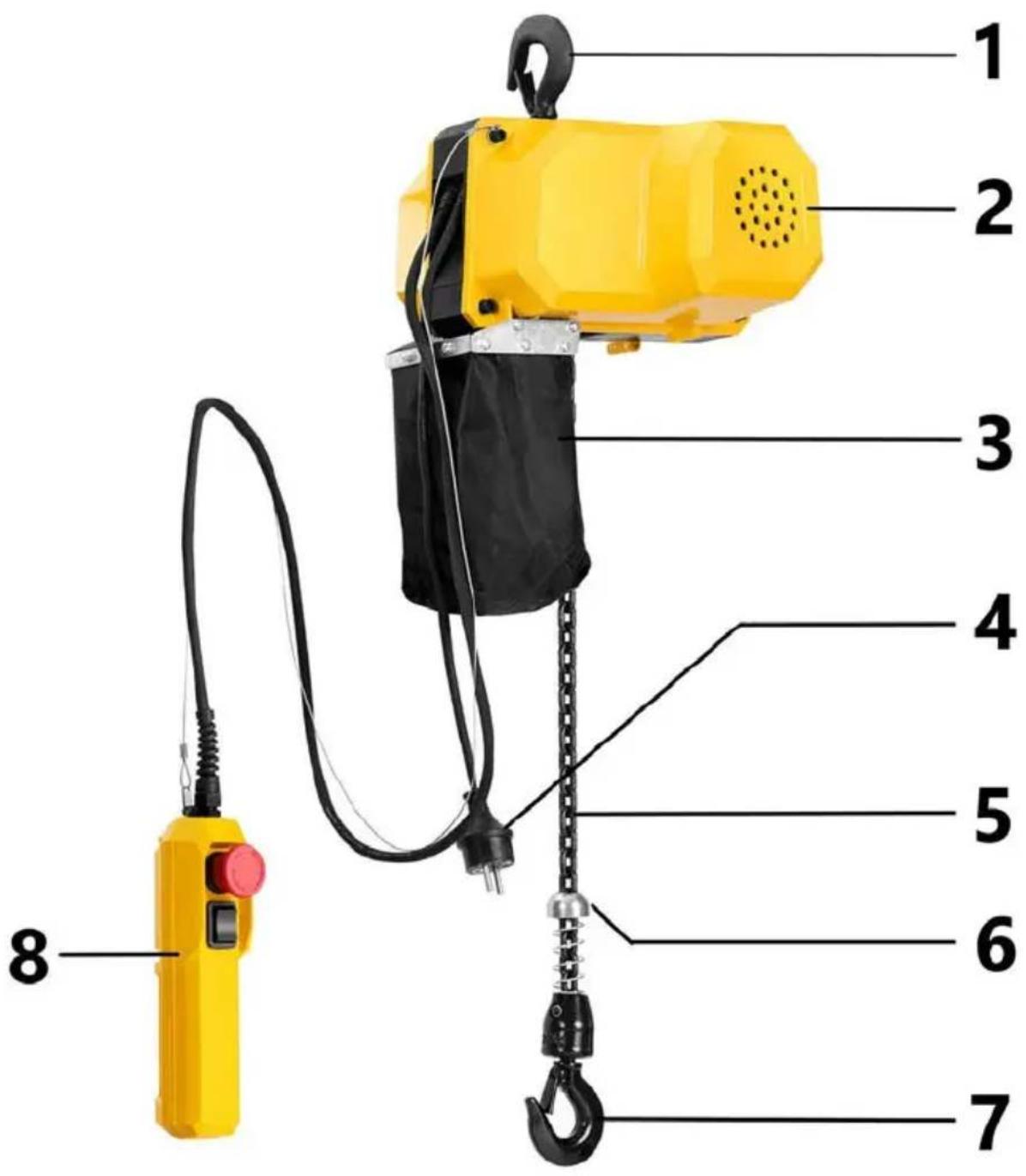
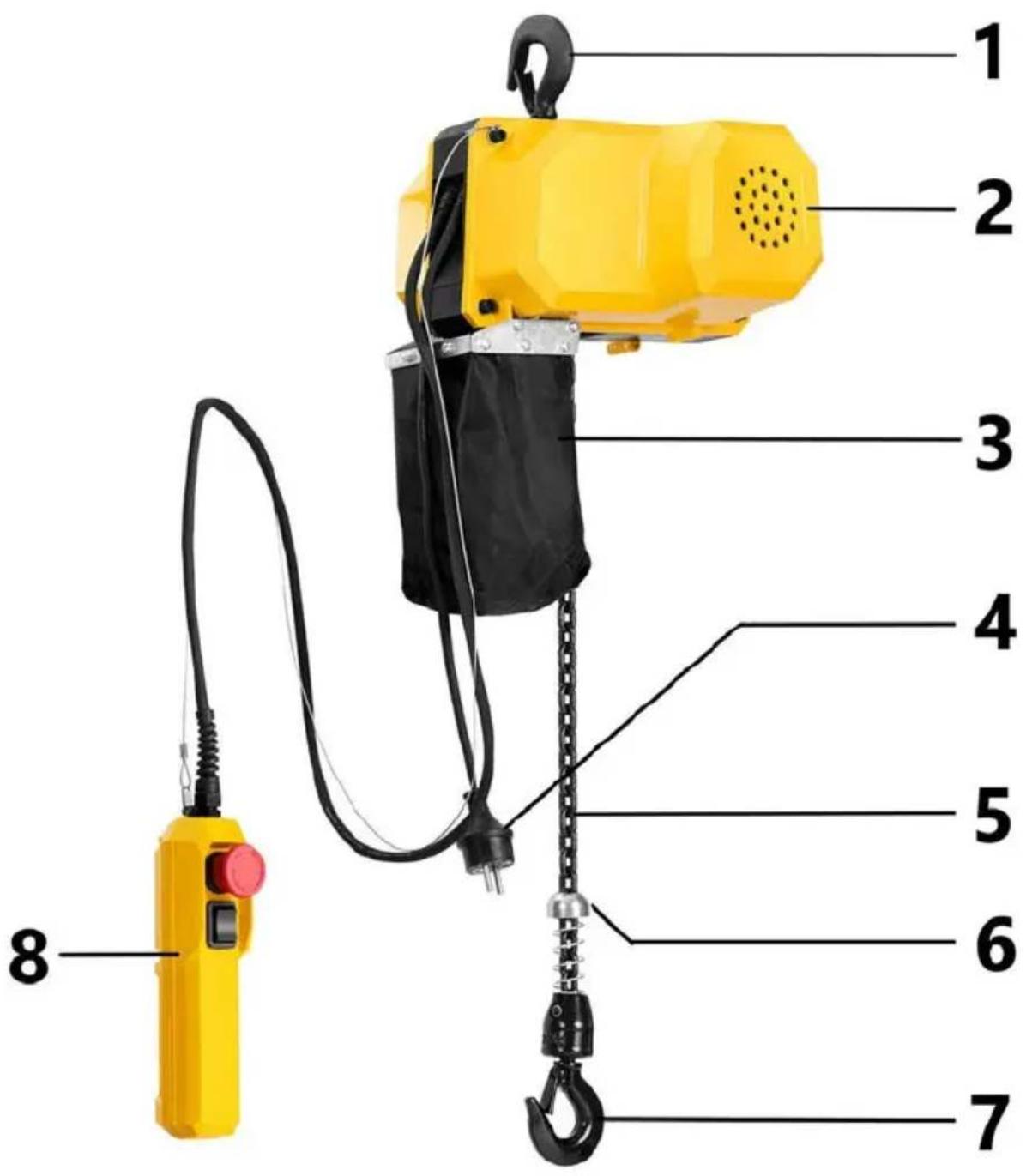
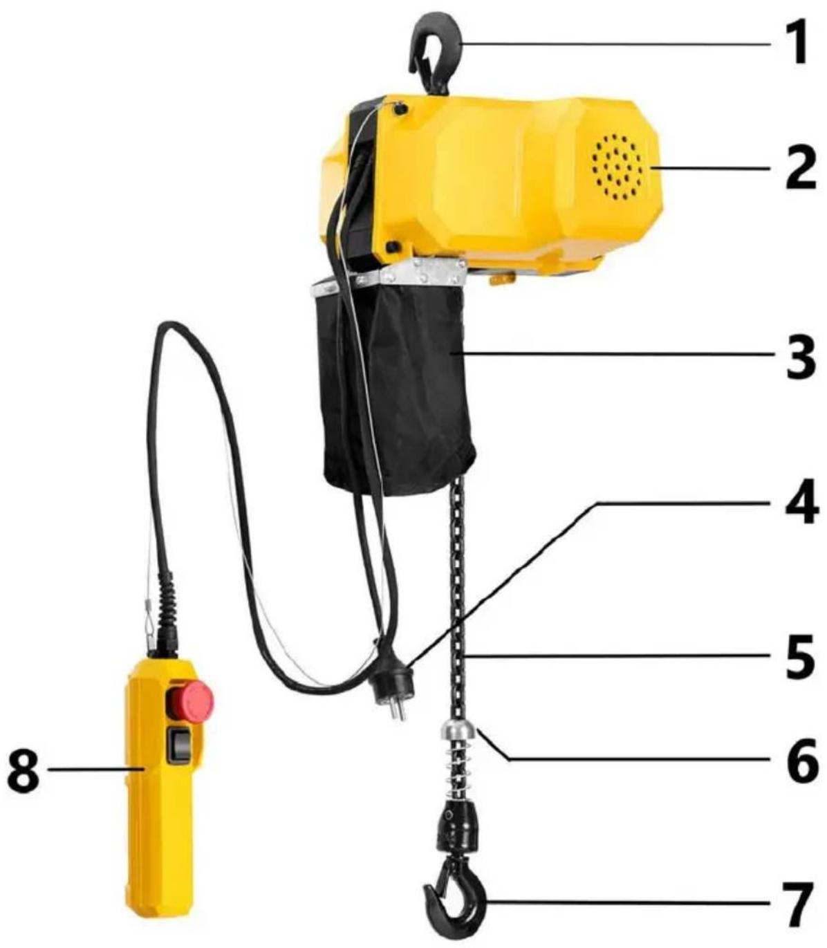
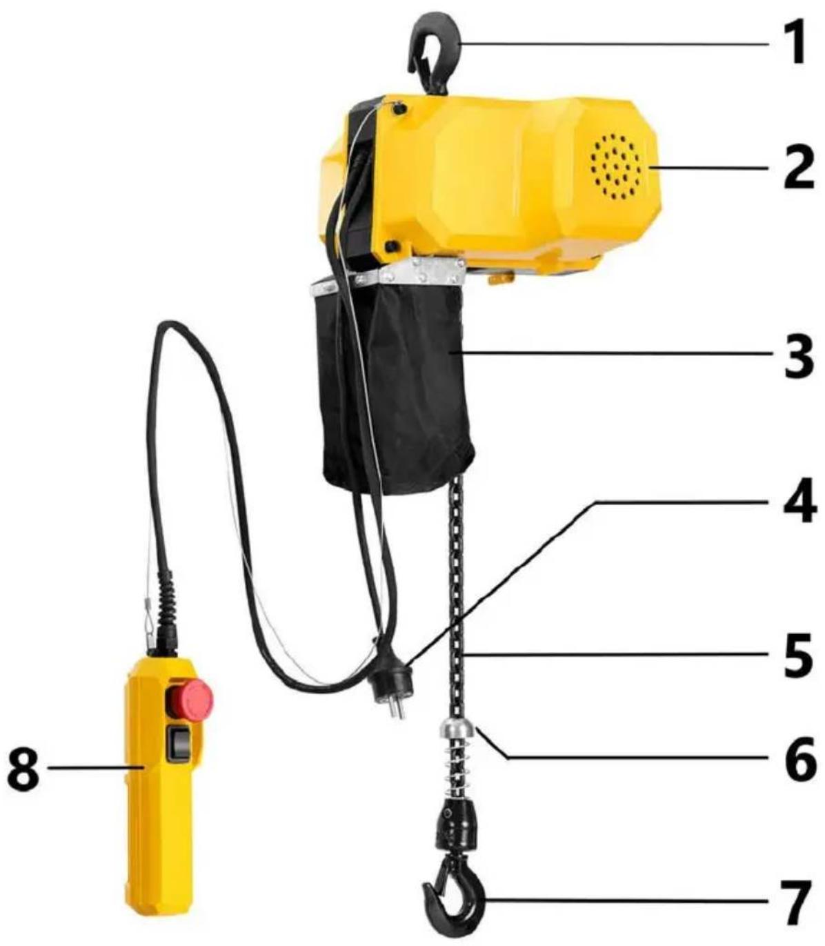
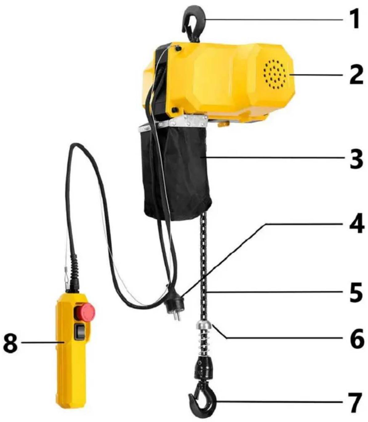
3.1. Product overview
SBS-ECH-500/3
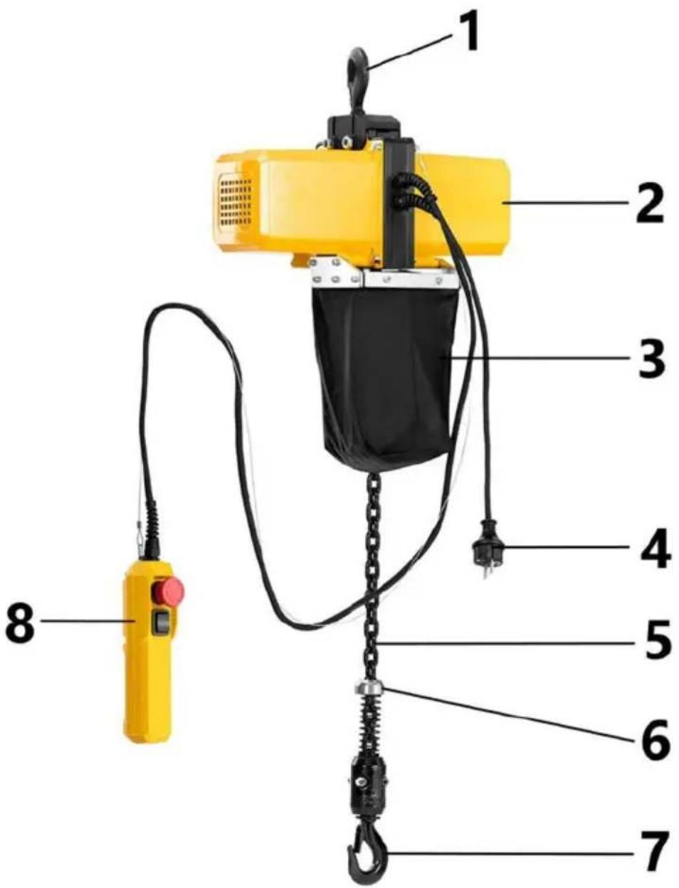
SBS-ECH-300/3, SBS-ECH-150/6, SBS-ECH-150/3
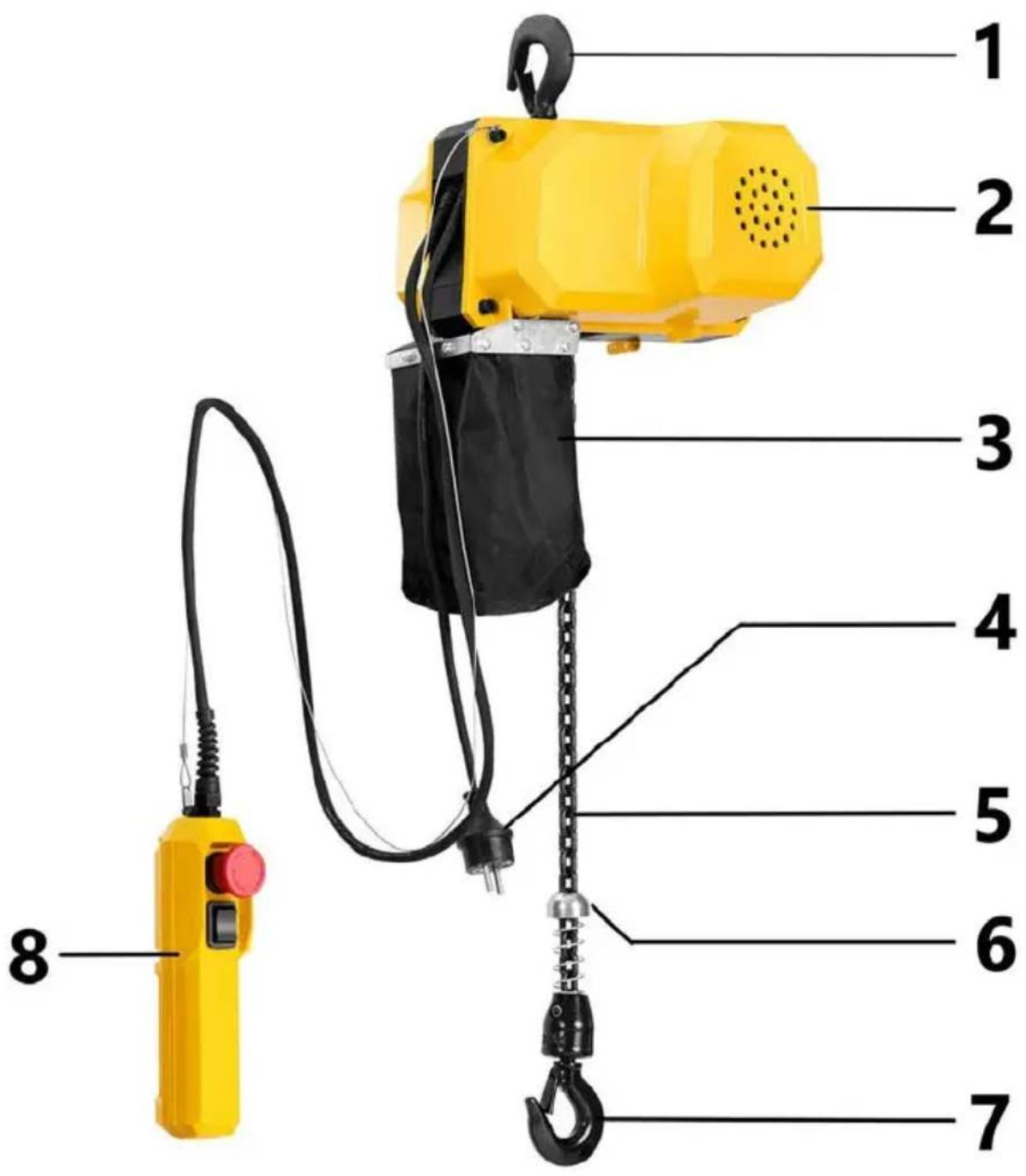
1 - Mounting hook
2 - Motor
3 - Bag for the loose end of the chain
4 - Power cable plug
5 - Chain
6 - Chain limiter
7 - Hook
8 - Wired remote control
3.2. Preparation for operation
ASSEMBLY OF THE UNIT
Before attaching the machine to the work area, check that it is not damaged. The structure used for suspending must be able to withstand a load several times greater than the maximum allowable load of the machine. Hang the machine on the mounting hook.
Improperly suspending the machine can make it to fall, become damaged, injure people or kill them.
It is forbidden to mount the machine on a structure that cannot be verified in terms of its load-bearing capacity and strength.
The responsibility for mounting on a support structure and for the support structure itself rests with the user. Special care must be taken when attaching the machine to the supporting structure, and all conditions for safe operation must be ensured in order to avoid hazards resulting in possible personal injury. The user is responsible for preparing the installation conditions for the machine and for the installation itself.
After mounting the machine, check that the hook is properly mounted and that the latch is closed. Always periodically check brake operation when lifting a load.
To do this, use a test load (approx. 10% of the permissible load) and raise and lower it several times to be sure that it will not slip off when lifting/lowering is stopped.
It must be possible to disconnect the device from the power supply at any moment. Ensure that the power supply to the unit corresponds to that specified on the identification plate!
Ambient conditions
The following table shows the permissible ambient conditions under which the machine can operate safely
| Ambient temperature during device operation [°C] | 0 ~ 40 |
| Relative humidity [%] | < 85 |
| Altitude [m above sea level] | < 1000 |
| Temp. of transport and storage [°C] | -25 ~ 55 |
3.3. Working with the device
Equipment Controls
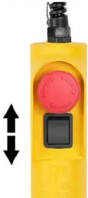
1) Verify that the Emergency Stop If the emergency stop switch is depressed, turn it in the direction of the arrow symbols to allow the machine to operate.
2) Press the switch according to the up arrow to lift the load.
3) Press the switch according to the down arrow to lower the load.
natural_image
Yellow handheld device with red circular button and black square button, shown with bidirectional arrow indicator (no text or symbols)4) If the load is lifted upward and the operator does not stop the machine early enough, the stop puck will move the lever upward and the limit switch will be activated. The machine will cease upward movement.
5) If the load is lowered down and the operator does not stop the machine early enough, the bottom limit puck will move the lever and the limit switch will activate. The machine will cease downward movement.
6) In an emergency situation, press the red button immediately to stop the machine. It is not possible to operate the machine while the emergency stop switch is depressed.
7) In the event of an overload, the winch speed is noticeably slower, jerking may occur or the load may not be lifted at all. In addition, if the winch is loaded above the rated capacity, the clutch may make a characteristic noise. In this case, immediately release the "Up" button to stop the machine, and then reduce the weight. After that, the machine can work again.
3.4. Cleaning and maintenance
a) Pull the mains plug and let the unit cool down completely before cleaning, adjusting or replacing accessories and when the unit is not in use.
b) Use only non-corrosive cleaning agents for cleaning the surfaces.
c) After each cleaning, all the parts should be dried well before the unit is used again.
d) Store the unit in a dry and cool place protected from moisture and direct sunlight.
e) Do not spray the unit with a stream of water or immerse it in water.
f) Make sure that no water enters through the ventilation openings in the casing.
g) Clean the ventilation openings with a brush and compressed air.
h) Perform regular inspections of the unit checking technical fitness and any damages.
i) Use a soft cloth for cleaning.
Periodic inspections
In order to ensure safe and trouble-free operation, it is recommended to perform regular technical inspections of the machine. Intervals between inspections should be determined individually, depending on the load and intensity of work to which the machine is subjected. Here is a list of activities and the recommended service interval:
Every six months:
1) Checking the correct tightness of the screws.
2) Inspect internal parts for wear, corrosion, cracks or distortions in the hook mounting block, gears, bearings, the chain stopper and the top hook.
3) Check for external signs of damage or excessive wear to the lifting wheel. Widening and deepening of the grooves can cause the chain to move in the grooves and jam between the lifting wheel and the chain guide. Check the chain guide for wear or burrs at the point where the chain enters the inside of the winch. Replace any seriously worn or damaged parts.
4) Check for signs of excessive wear of the brake parts.
5) Check the buttons on the wired remote control to make sure they are working properly.
6) Check the condition of the insulation of the power cable, control cable and control box.
7) Check the hook pin and the chain end for wear and cracks.
Note: Any damage must be repaired before returning the machine to service.
Hook inspection
- Long service life, high-intensity work or overloading can lead to hook damage. When checking the technical condition of the hook, pay special attention to damage from corrosive substances, deformations, cracks, twisting more than 10^ from the centre or excessive opening of the hook.
- Check that the latch is not damaged or bent and that it is working properly. Check the spring pressure by pressing the latch against the inner wall of the hook and allowing the latch to return to the tip of the hook. If the latch does not function properly, replace it.
Chain inspection
1) The chain should be replaced if it has any of the following defects:
- material losses
- twisted links
- welding spatter
- corrosion
- cracks
• deformation due to stretching
For safety reasons, the replacement of a damaged chain should be performed by the manufacturer's service or a person with appropriate qualifications.
2) Lubricate the chain with calcium III-based grease every 200 cycles. The service life of the chain is approximately 50,000 cycles.
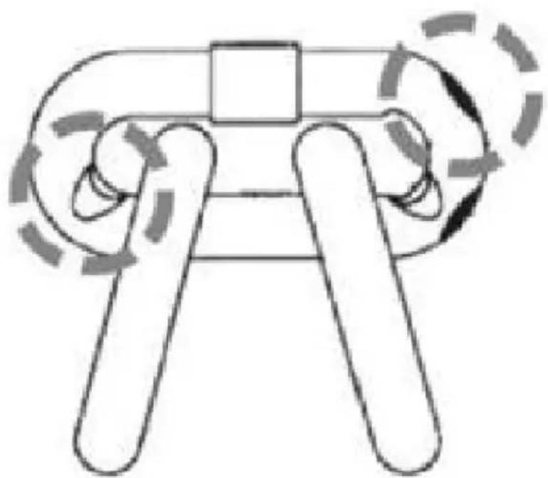
3) Chain control with callipers: Loosen the part of the chain that would normally pass through the lifting wheel and check the inside of the link for signs of wear. Measure with a calliper and note the diameter of the material at the points in the link where damage is visible.
natural_image
Simple line drawing of a mechanical or electrical component with no text, numbers, or symbolsThen measure the diameter of the material in the same area on a link that does not normally pass through the lifting wheel (e.g. near the end of the chain). Compare the two measurements. If the diameter is smaller by 0.25 mm or more, the chain must be replaced. The chain should be replaced by the manufacturer's service or a qualified person.
Here are the dimensions of the chain links depending on the model of the device:
- SBS-ECH-500/3
- SBS-ECH-300/3
• SBS-ECH-150/6 and SBS-ECH-150/3
Lubrication
The gears are originally lubricated and require no maintenance. The exception is when the gears have been removed and the grease has been removed.
Bearings
The machine's bearings are originally lubricated and do not require regular lubrication. If the bearings have been de-greased on purpose, they should be lubricated with lithium grease.
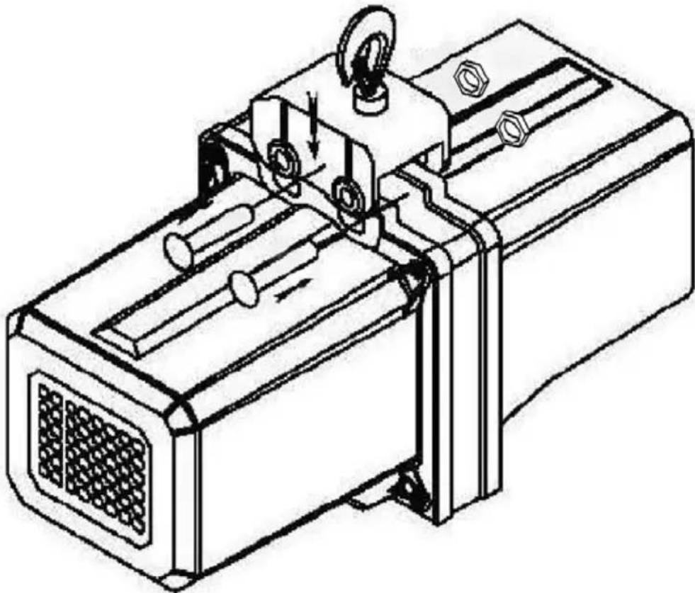
Installing the top hook
(Applies to SBS-ECH-500/3 only)
1) Align the holes in the top hook block with the holes on the winch housing.
2) Insert the bolts through the holes and secure the connections with nuts.
natural_image
Technical line drawing of a mechanical device with internal components and mounting holes (no text or symbols)Disposal of used devices
At the end of its useful life, this product should not be disposed of with normal household waste but should be taken to a collection point for the recycling of electrical and electronic equipment. This is indicated by the symbol on the product, operating instructions or packaging. The materials used in this appliance are recyclable according to their marking. By reuse, recycling or applying other forms of use of waste machines, you make a significant contribution to the protection of our environment.
Your local administration will provide you with information about the appropriate disposal point for used appliances.
3.5. Electrical diagram
SBS-ECH-300/3
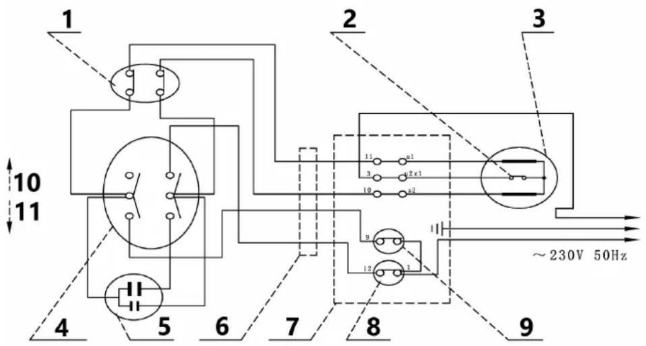
SBS-ECH-500/3, SBS-ECH-150/6, SBS-ECH-150/3
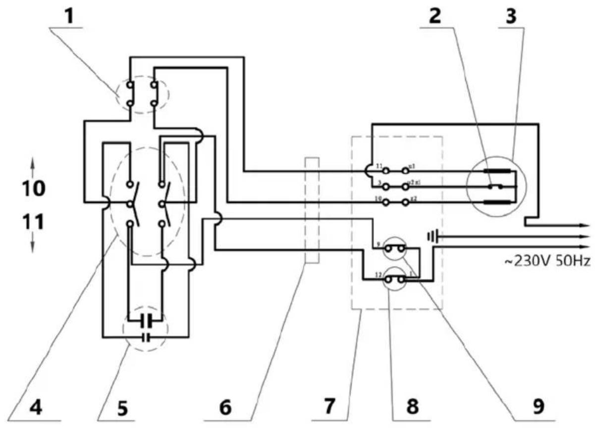
1 - Emergency stop
2 - Protection against overheating
3 - Motor
4 - Switch
5 - Capacitor
6 - Control cable
7 - Control box
8 - Down movement limit switch
9 - Up movement limit switch
10 - Up
11 - Down
3.6. Assembly drawings
Exploded view of the SBS-ECH-500/3 model
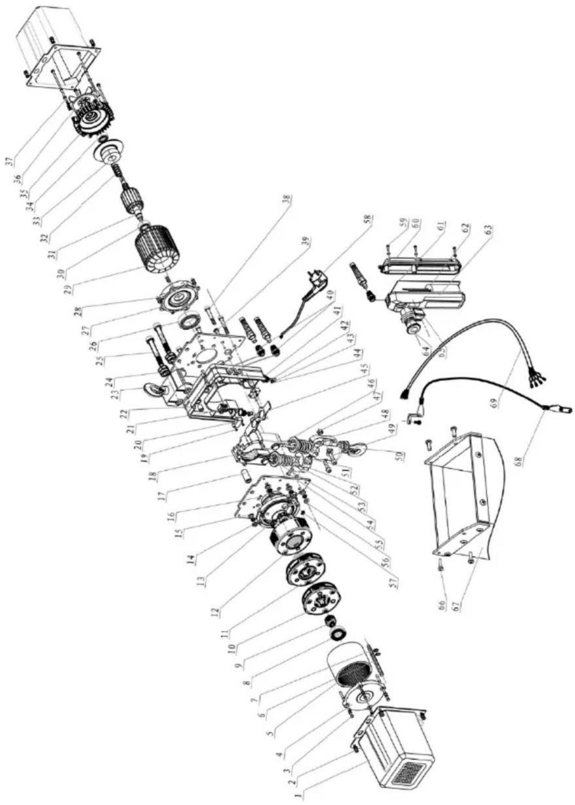
| No. | Part name | Quantity |
| 1 | Fan cover | 2 |
| 2 | M6 * 12 cross socket screw | 8 |
| Flat washer M6 | ||
| Spring washer M6 | ||
| 3 | M6 * 85 hexagon bolt | 4 |
| Flat washer M6 | ||
| Spring washer M6 | ||
| 4 | Reduction gear rear cover | 1 |
| 5 | Toothed ring | 1 |
| 6 | Hexagonal drive shaft | 1 |
| 7 | Shaft retaining ring M8 | 2 |
| 8 | Deep groove ball bearing 6002-2RS | 1 |
| 9 | Main drive wheel | 1 |
| 10 | First degree planetary wheel | 1 |
| 11 | Second-degree planetary wheel | 1 |
| 12 | Third-degree planetary wheel | 1 |
| 13 | Gear flange | 1 |
| 14 | M6 * 14 hexagon socket screw | 4 |
| Flat washer M6 | ||
| Spring washer M6 | ||
| 15 | Plate | 2 |
| 16 | Large nylon bearing bushing | 1 |
| 17 | Hexagonal connecting sleeve | 1 |
| 18 | Chain guide | 2 |
| 19 | Self-tapping screw with cross socket ST2.9 * 14.7 | 6 |
| 20 | Limit switch | 2 |
| 21 | Connector | 1 |
| 22 | Support frame | 1 |
| 23 | Hook (top) | 1 |
| 24 | M10 lock nut | 2 |
| 25 | M10x75 hexagon socket screw | 2 |
| 26 | Deep groove ball bearing 6007-2RS | 1 |
| 27 | Front motor cover | 1 |
| 28 | M6x12 hexagon socket screw | 4 |
| Flat washer M6 | ||
| Spring washer M6 | ||
| 29 | Stand | 1 |
| 30 | Deep groove ball bearing 6202-2RS | 1 |
| 31 | Rotor | 1 |
| 32 | Brake spring | 1 |
| 33 | Brake parts set | 1 |
| 34 | Deep groove ball bearing 6202-2RS | 1 |
| 35 | Engine rear cover | 1 |
| 36 | Fan blade | 1 |
| 37 | Hexagon bolt M5x135 | 4 |
| 38 | M8 * 55 hexagon socket screw | 6 |
| 39 | Flat head spindle | 1 |
| 40 | Cable clip (thick) | 1 |
| Cable clip (thin) | 2 | |
| 41 | Limit switch stem cover | 2 |
| 42 | Limit switch spring | 2 |
| 43 | Limiting shaft | 2 |
| 44 | 6mm E-ring | 2 |
| 45 | Limit switch lever | 2 |
| 46 | Chain | 1 |
| 47 | M8 lock nut | 2 |
| 48 | Hook block | 2 |
| 49 | M8 * 30 hexagon socket screw | 2 |
| 50 | Hook (bottom) | 1 |
| 51 | M6 lock nut | 2 |
| 52 | Spring | 2 |
| 53 | Chain mounting block | 2 |
| 54 | Gasket | 2 |
| 55 | M6 * 30 hexagon socket screw | 2 |
| 56 | Hexagonal nut M8 | 6 |
| Spring washer M8 | ||
| Flat washer M8 | ||
| 57 | 5mm E-ring | 1 |
| 58 | Plug | 1 |
| 59 | Cross socket screw ST4.2 * 18 | 5 |
| Small washer d4 | ||
| 60 | Rear cover of the remote control | 1 |
| 61 | Pilot gasket | 1 |
| 62 | Capacitor | 1 |
| 63 | Front cover of the remote control | 1 |
| 64 | Emergency stop | 1 |
| 65 | Direction switch | 1 |
| 66 | M5 * 16 cross socket screw | 4 |
| 67 | Chain bag | 1 |
| 68 | Wire | 1 |
| 69 | Control cable | 1 |
Exploded view of the SBS-ECH-300/3 model
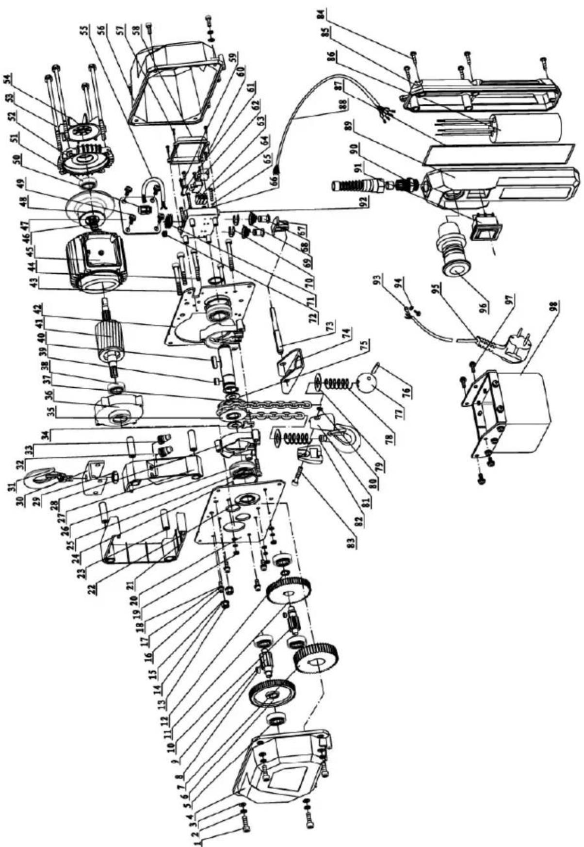
SBS-ECH-300/3 parts list
| No. | Part name | Pcs | No. | Part name | Pcs |
| 1 | Hexagon socket screw | 8 | 50 | Cable clip | 1 |
| 2 | Spring washer | 11 | 51 | Bearing | 1 |
| 3 | Normal washer | 11 | 52 | Engine rear cover | 1 |
| 4 | Casing | 1 | 53 | Hexagonal head screw | 4 |
| 5 | Bearing | 4 | 54 | Fan blade | 1 |
| 6 | Gear wheel of the second stage of the gearbox | 1 5 | 5 | Cable | 1 |
| 7 | Gear wheel of the third stage of the gearbox | 1 5 | 6 | Casing | 1 |
| 8 | Flat pin 2 57 | Self-tapping screw with cross socket | 4 | ||
| 9 | Second gear shaft 1 58 | Connection box | 1 | ||
| 10 | First gear shaft 1 59 | Self-tapping screw with cross socket | 4 | ||
| 11 | Gear wheel of the first stage of the gearbox | 1 6 | 0 | Self-tapping screw with cross socket | 5 |
| 12 | Shaft locking ring | 1 | 61 | Pressure plate | 1 |
| 13 | Thin hexagonal nuts 2 62 | Limit switch | 2 | ||
| 14 | Spring washer | 2 | 63 | Terminal block | 1 |
| 15 | Normal washer | 2 | 64 | Hexagon socket screw | 4 |
| 16 | Hexagon socket screw | 4 | 65 | Spring washer | 4 |
| 17 | Spring washer | 4 | 66 | Normal washer | 4 |
| 18 | Normal washer 4 67 | Pressure lever of the limit switch | 1 | ||
| 19 | Thin hexagonal nut | 3 | 68 | Limit switch pin | 2 |
| 20 | Plate | 1 | 69 | Limit switch spring | 2 |
| 21 | Right cover | 1 | 70 | E-ring | 2 |
| 22 | Shaft locking ring | 3 | 71 | Cable cover | 1 |
| 23 | Support | 4 | 72 | Earthing cover | 1 |
| 24 | Shaft locking ring | 2 | 73 | Limiter lever shaft | 1 |
| 25 | Hexagon socket screw | 1 | 74 | Limiter lever | 1 |
| 26 | Bearing 2 75 | Normal washer | 2 | ||
| 27 | Left cover | 1 | 76 | Spring pin | 1 |
| 28 | Chain cover 2 77 | Chain mounting block | 1 | ||
| 29 | Thin hexagonal nut | 1 | 78 | Spring | 2 |
| 30 | Hook base 1 79 | Cover | 2 | ||
| 31 | Hook | 1 | 80 | Lock nut | 1 |
| 32 | Control cable cover 1 81 | Hook block | 2 | ||
| 33 | Power cord cover | 1 | 82 | Hook | 1 |
| 34 | Partition 1 83 | Hexagon socket screws | 1 | ||
| 35 | Chain wheel 1 84 | Self-tapping screw with cross socket | 7 | ||
| 36 | Front motor cover 1 85 | Rear cover of the remote control | 1 | ||
| 37 | Chain | 1 | 86 | Capacitor | 1 |
| 38 | Bearing | 1 | 87 | Pilot gasket | 1 |
| 39 | Flat pin | 1 | 88 | Control cable | 1 |
| 40 | Flat pin 1 89 | Front cover of the remote control | 1 | ||
| 41 | Rotor | 1 | 90 | Cable cover | 1 |
| 42 | Engine plate | 1 | 91 | Direction switch | 1 |
| 43 | Hexagon socket screw | 2 | 92 | Base of the connection box | 1 |
| 44 | Hexagon socket screw | 4 | 93 | Grounding terminal | 1 |
| 45 | Stand | 1 | 94 | Gasket | 1 |
| 46 | Brake spring | 1 | 95 | Plug | 1 |
| 47 | Motor cable cover | 1 | 96 | Emergency stop | 1 |
| 48 | Brake set | 1 | 97 | Hexagon socket screw | 4 |
| 49 | Cross-socket screws | 5 | 98 | Chain bag | 1 |
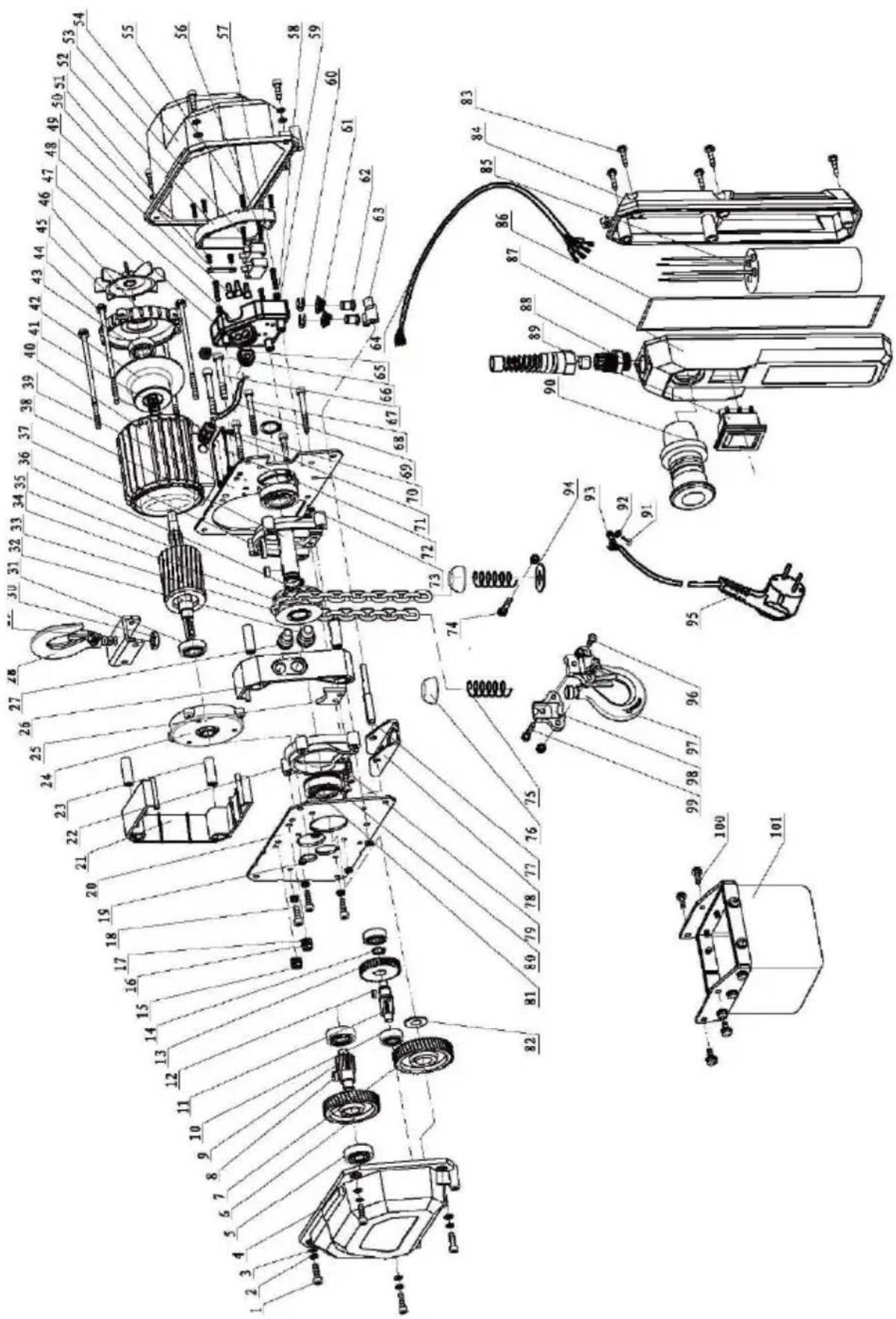
SBS-ECH-150 / 6-801 and SBS-ECH-150/3 parts list
| No. | Part name Pcs | No. | Part name | Pcs | |
| 1 | Hexagon socket screw | 8 | 52 | Connection box | 1 |
| 2 | Spring washer | 11 53 | Limit switch | 2 | |
| 3 | Normal washer | 11 | 54 | Casing | 1 |
| 4 | Casing | 1 55 | Self-tapping screw with cross socket | 5 | |
| 5 | Bearing | 2 56 | Self-tapping screw with cross socket | 2 | |
| 6 | Gear wheel of the second stage of the gearbox | 1 57 | Hexagon socket screw | 3 | |
| 7 | Gear wheel of the third stage of the gearbox | 1 58 | Spring washer | 3 | |
| 8 | Flat pin | 1 | 59 | Normal washer | 3 |
| 9 | Second gear shaft | 1 60 | E-ring | 2 | |
| 10 | Bearing | 2 | 61 | Limit switch spring | 2 |
| 11 | First gear shaft | 1 62 | Limit switch pin | 2 | |
| 12 | Flat pin | 1 | 63 | Pressure lever of the limit switch | 1 |
| 13 | Gear wheel of the first stage of the gearbox | 1 64 | Control cable | 1 | |
| 14 | Shaft locking ring | 1 | 65 | Motor cable cover | 1 |
| 15 | Thin hexagonal nut | 2 66 | Earthing cover | 1 | |
| 16 | Spring washer | 2 | 67 | Hexagon socket screw | 2 |
| 17 | Normal washer | 2 68 | Hexagon socket screw | 4 | |
| 18 | Hexagon socket screws | 3 | 69 | Cable | 1 |
| 19 | Hexagon nut | 8 70 | Cable clip | 1 | |
| 20 | Plate | 1 | 71 | Hexagon socket screw | 4 |
| 21 | Right cover | 1 72 | Engine cover | 1 | |
| 22 | Chain cover | 2 | 73 | Hexagon nut | 2 |
| 23 | Support | 4 74 | Hexagon socket screw | 1 | |
| 24 | Front motor cover | 1 | 75 | Spring | 2 |
| 25 | Partition | 1 76 | Cover | 2 | |
| 26 | Left cover | 1 | 77 | Limiter lever shaft | 1 |
| 27 | Power cord cover | 1 78 | Limiter lever | 1 | |
| 28 | Hook | 1 | 79 | Hexagon socket screw | 2 |
| 29 | Hook base | 1 80 | Bearing | 2 | |
| 30 | Thin hexagonal nut | 1 | 81 | Shaft locking ring | 2 |
| 31 | Bearing | 1 82 | Thick washer | 1 | |
| 32 | Control wires cover | 1 83 | Self-tapping screw with cross socket | 5 | |
| 33 | Chain wheel | 1 | 84 | Rear cover of the remote control | 1 |
| 34 | Chain | 1 | 85 | Capacitor | 1 |
| 35 | Rotor | 1 | 86 | Pilot gasket | 1 |
| 36 | Shaft locking ring | 2 | 87 | Front cover of the remote control | 1 |
| 37 | Flat pin | 1 | 88 | Cable clip | 1 |
| 38 | Sprocket shaft | 1 | 89 | Direction switch | 1 |
| 39 | Engine plate | 1 | 90 | Emergency stop | 1 |
| 40 | Stand | 1 | 91 | Hexagon socket screw | 1 |
| 41 | Brake spring | 1 | 92 | Gasket | 1 |
| 42 | Brake set | 1 | 93 | Grounding terminal | 1 |
| 43 | Bearing | 1 | 94 | Cover | 2 |
| 44 | Hexagonal head screw | 4 | 95 | Plug | 1 |
| 45 | Fan blade | 1 | 96 | Hexagon socket screw | 2 |
| 46 | Engine rear cover | 1 | 97 | Hook | 1 |
| 47 | Cable cover | 1 | 98 | Hook block | 1 |
| 48 | Base of the connection box | 1 | 99 | Hexagon socket screw | 1 |
| 49 | Cable cover | 3 | 100 | Hexagon socket screw | 1 |
| 50 | Pressure plate | 1 | 101 | Chain bag | 1 |
| 51 | Self-tapping screw with cross socket | 2 | |||
SBS-ECH-300/3, SBS-ECH-150/6, SBS-ECH-150/3
natural_image
Yellow industrial device with red circular button and black base, showing upward and downward arrows (no text or symbols)natural_image
Simple line drawing of a mechanical device with no text or symbolsnatural_image
Technical line drawing of a mechanical device with internal components and mounting holes (no text or symbols)SBS-ECH-300/3, SBS-ECH-150/6, SBS-ECH-150/3
natural_image
Yellow industrial device with red circular button and black top, showing bidirectional arrow (no text or symbols)natural_image
Simple line drawing of a mechanical device with no text or symbolsnatural_image
Technical line drawing of a mechanical device with internal components and mounting holes (no text or symbols)
natural_image
Yellow industrial device with red circular button and black square base, shown with bidirectional arrow indicator (no text or symbols)natural_image
Simple line drawing of a mechanical device with no text or symbolsnatural_image
Technical line drawing of a mechanical device with internal components and mounting holes (no text or symbols)SBS-ECH-300/3, SBS-ECH-150/6, SBS-ECH-150/3
natural_image
Yellow industrial device with red circular button and black base, showing upward and downward arrows (no text or symbols)natural_image
Simple line drawing of a mechanical device with no text or symbols(Si applica solo a SBS-ECH-500/3)
natural_image
Technical line drawing of a mechanical device with internal components and mounting holes (no text or symbols)Elenco parti SBS-ECH-300/3
SBS-ECH-300/3, SBS-ECH-150/6, SBS-ECH-150/3
natural_image
Yellow industrial device with red circular button and black base, showing bidirectional arrow indicator (no text or symbols)natural_image
Simple line drawing of a mechanical device with no text or symbolsnatural_image
Technical line drawing of a mechanical device with internal components and mounting holes (no text or symbols)SBS-ECH-300/3, SBS-ECH-150/6, SBS-ECH-150/3
natural_image
Yellow industrial device with red circular button and black top, showing bidirectional arrow (no text or symbols)natural_image
Simple line drawing of a mechanical device with no text or symbolsnatural_image
Technical line drawing of a mechanical device with internal components and mounting holes (no text or symbols)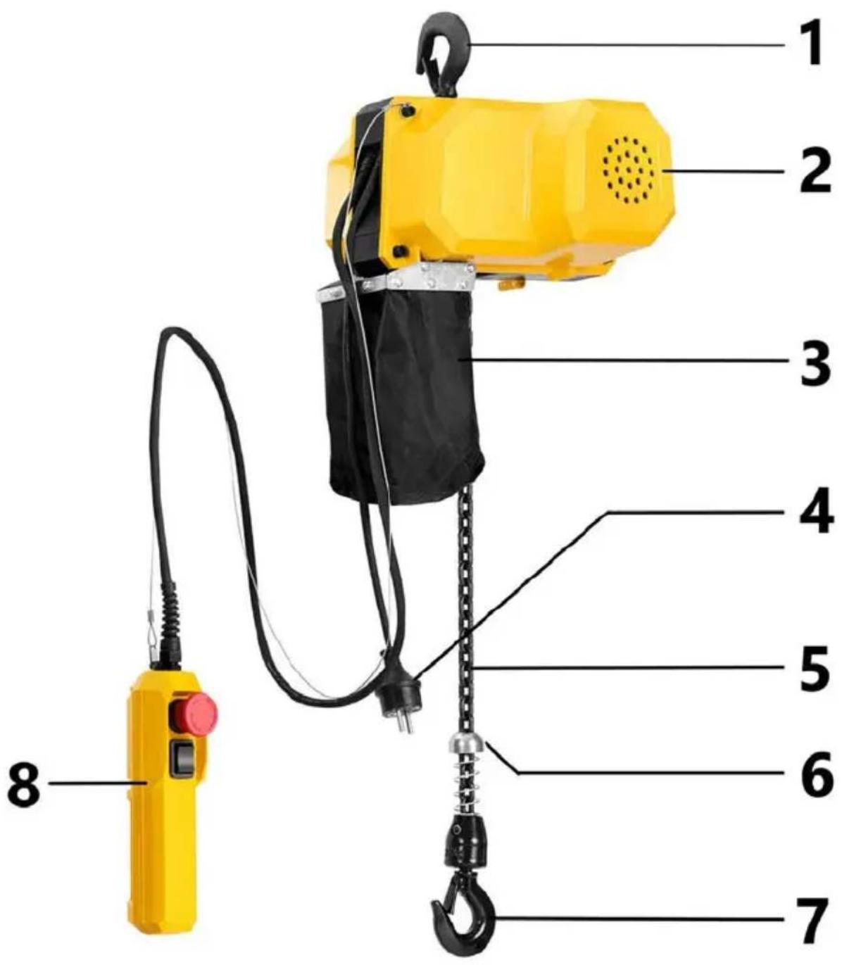
natural_image
Yellow handheld device with red circular button and black top, showing bidirectional arrow (no text or symbols)natural_image
Simple line drawing of a mechanical device with no text or symbolsnatural_image
Technical line drawing of a mechanical device with internal components and mounting holes (no text or symbols)SBS-ECH-300/3 reservedelsliste
SBS-ECH-150 / 6-801 og SBS-ECH-150/3 stykliste
For the disposal of the device please consider and act according to the national and local rules and regulations.
CONTACT
expondo Polska sp. z o.o. sp. k.
- General Description
- CAREFULLY READ AND UNDERSTAND THIS MANUAL BEFORE STARTING THE WORK.
- Explanation of symbols
- CAUTION! The figures in this manual are illustrative only and may vary in some details from the actual appearance of the product.
- Safety of use
- Electrical safety
- Safety in the workplace
- Personal safety
- Safe use of the device
- Instructions for use
- Product overview
- Preparation for operation
- ASSEMBLY OF THE UNIT
- Ambient conditions
- Working with the device
- Cleaning and maintenance
- Periodic inspections
- Every six months:
- Hook inspection
- Chain inspection
- Lubrication
- Bearings
- Installing the top hook
- Disposal of used devices
- Electrical diagram
- Assembly drawings
- CONTACT
Brand : STEINBERG
Model : SBS-ECH-150/6
Category : Electric hoist