
VB16Y - Grinder HITACHI - Free user manual and instructions
Find the device manual for free VB16Y HITACHI in PDF.

| Product Type | Rebar Cutter and Bender |
| Brand | Hitachi |
| Model | VB16Y |
| Supply Voltage | 120 V, 60 Hz, Single Phase |
| Rated Current | 8 A |
| Approximate Power | 960 W |
| Cutting Capacity (Steel) | Bars #3 (3/8"), #4 (1/2"), #5 (5/8") - Grades 40 and 60 |
| Bending Capacity | Adjustable Angles: 45°, 90°, 135°, 180° |
| No Load Speed | 0 - 16 cycles/min |
| Weight (without cord) | 18 kg |
| Double Insulation | Yes, Class II |
| Main Functions | Cutting and bending rebar |
| Safety Devices | Kickback protection, blade guard, automatic stop |
| Routine Maintenance | Check and replace blades, check carbon brushes |
| Blade Lifespan | Approximately 5,000 cuts |
| Supplied Accessories | Allen key, blade set, kickback guard |
Frequently Asked Questions - VB16Y HITACHI
User questions about VB16Y HITACHI
0 question about this device. Answer the ones you know or ask your own.
Ask a new question about this device
Download the instructions for your Grinder in PDF format for free! Find your manual VB16Y - HITACHI and take your electronic device back in hand. On this page are published all the documents necessary for the use of your device. VB16Y by HITACHI.
USER MANUAL VB16Y HITACHI
natural_image
Technical line drawing of a mechanical device with internal components and a separate exploded view (no text or symbols)SAFETY INSTRUCTIONS AND INSTRUCTION MANUAL
WARNING
IMPROPER OR UNSAFE use of this power tool can result in death or serious bodily injury!
This manual contains important information about product safety. Please read and understand this manual BEFORE operating the power tool. Please keep this manual available for other users and owners before they use the power tool.
This manual should be stored in safe place.
INSTRUCTIONS DE SECURITE ET MODE D'EMPLOI
AVERTISSEMENT
PICTGRAPH ILLUSTRATION AND EXPLANATION .... 13
HOW TO USE (CUTTING) 15
SERVICE LIFE AND REPLACEMENT OF THE CUTTER 16
HOW TO USE (BENDING) 17
MAINTENANCE AND INSPECTION 22
ACCESSORIES 23
STANDARD ACCESSORIES 23
OPTIONAL ACCESSORIES 23
TABLE DES MATIERES
Français
Page Page
INFORMATIONS IMPORTANTES ...... 24
SIGNIFICATION DES MOTS D'AVERTISSEMENT .... 24
SECURITE 25
CONSIGNES DE SECURITE RELATIVES AUX OUTILS ELECTRIQUES 25
REGLES DE SECURITE SPECIFIQUES ET SYMBOLES 27
PIECES DE RECHANGE 28
UTILISER LE CORDON DE RALLONGE APPROPRIÉ .... 29
DOUBLE ISOLATION POUR UN FONCTIONNEMENT PLUS SUR .... 30
DESCRIPTION FONCTIONNELLE 31
NOM DES PARTIES 31
SPECIFICATIONS 32
ASSEMBLAGE ET FONCTIONNEMENT ...... 33
APPLICATIONS 33
Read and understand all of the operating instructions, safety precautions and warnings in the Instruction Manual before operating or maintaining this power tool.
Most accidents that result from power tool operation and maintenance are caused by the failure to observe basic safety rules or precautions. An accident can often be avoided by recognizing a potentially hazardous situation before it occurs, and by observing appropriate safety procedures.
Basic safety precautions are outlined in the “SAFETY” section of this Instruction Manual and in the sections which contain the operation and maintenance instructions.
Hazards that must be avoided to prevent bodily injury or machine damage are identified by WARNINGS on the power tool and in this Instruction Manual.
Never use this power tool in a manner that has not been specifically recommended by HITACHI, unless you first confirm that the planned use will be safe for you and others.
MEANINGS OF SIGNAL WORDS
WARNING indicates a potentially hazardous situation which, if ignored, could result in serious personal injury.
CAUTION indicates a hazardous situation which, if ignored, could result in moderate personal injury, or could cause machine damage.
NOTE emphasizes essential information.
SAFETY
IMPORTANT SAFETY INSTRUCTIONS FOR USING ALL POWER TOOLS
READ ALL OF THE WARNINGS AND OPERATING INSTRUCTIONS IN THIS MANUAL BEFORE OPERATING OR MAINTAINING THIS TOOL:

WARNING: When using this electric tool, take all necessary precautions to minimize the risk of electric shock or other personal injury.
In particular, always comply with the following safety rules:
- ALWAYS KEEP GUARDS IN PLACE and in working order.
- ALWAYS REMOVE ADJUSTING KEYS AND WRENCHES BEFORE STARTING TOOL.
Always confirm that all keys and adjusting wrenches have been removed from the tool before it is turned on. - ALWAYS KEEP WORK AREA CLEAN. Avoid injuries by not cluttering the work areas and work benches.
- NEVER USE TOOL IN HAZARDOUS ENVIRONMENTS. Never use the power tool in damp or wet places and never expose it to rain. Always keep the work area well lighted.
- NEVER PERMIT CHILDREN OR OTHERS TO LOITER NEAR THE WORK AREA. Keep all people (especially children) away from the work area. Always unplug unattended tools and keep the work place tamper-proof by installing locks on the doors and on the master switches. Always remove the lock-off button from the tool and store it in a secure place, when the tool is not in use.
- NEVER FORCE THE TOOL. It will do the job better and more safely if it is operated at the rate for which it was designed.
- ALWAYS USE THE RIGHT TOOLS. Never force a tool or an attachment to do a job for which it was not designed.
- ALWAYS WEAR PROPER APPAREL WHEN WORKING WITH THE TOOL. Never wear loose clothing, gloves, neckties, rings, bracelets or other jewelry which may get caught in the moving parts. Always wear non-slip footwear, preferably with steel toes. Wear protective hair covering to contain long hair.
- ALWAYS USE EYE PROTECTION WHEN WORKING WITH THE TOOL TO PREVENT EYE INJURY. Ordinary eyeglasses do not provide adequate protection because the lenses are not made of safety glass. Also, use a face mask for additional safety and wear a dust mask if the cutting/bending operation produces dust.
- ALWAYS SECURE THE WORKPIECE TO THE FENCE OR THE TABLE. Use clamps or a vise to hold the workpiece in place. It is safer than using your hand and it frees both hands to operate the tool.
- NEVER OVERREACH. Always keep proper footing and balance when working with the tool.
-
ALWAYS MAINTAIN TOOLS WITH CARE. Always keep tools sharp and clean for the best and safest performance. Always follow instructions for lubricating the tool and for changing accessories.receptacle.
-
ALWAYS DISCONNECT THE TOOL before servicing and before changing blades or other accessories.
- NEVER RISK UNINTENTIONAL STARTING WHEN PLUGGING IN THE TOOL. Always confirm that the switch is in the OFF position before inserting the power plug into the
- ALWAYS USE RECOMMENDED ACCESSORIES ONLY WHEN OPERATING THIS TOOL. Consult this instruction manual for descriptions of recommended accessories. To avoid personal injuries, use only recommended accessories in conjunction with this tool.
- NEVER STAND ON THE TOOL. Prevent serious injury by not tipping the tool and by not risking unintentional contact with the cutter.
- ALWAYS CHECK FOR DAMAGED PARTS BEFORE USING THE TOOL. Always check the guard and all other components for damage before using the tool to assure that they will function properly. Check all moving parts for proper alignment, freedom from binding and other conditions that might affect proper operation. Always repair or replace any damaged guards or other damaged components before using the tool.
- ALWAYS CONFIRM THE ROTATION DIRECTION OF THE BLADE BEFORE USING THE TOOL. Always feed work into the tool against the moving direction of the cutter in order to prevent possible injury.
- NEVER LEAVE THE TOOL RUNNING WHILE UNATTENDED. TURN POWER OFF. Do not leave tool until it comes to a complete stop. Always turn the power off when the tool is not in use. Always unplug the power cord when the tool is not in use.
- This tool was not designed to be used for mass-production applications and should not be used in mass-production environments.
- When servicing this tool, use only authorized replacement parts.
- Apply 120 volts AC only to this tool. Applying the wrong voltage or applying DC power can cause the POWER TOOL to operate improperly and cause serious personal injury or damage to the tool.
- POLARIZED PLUGS To reduce the risk of electric shock, this equipment has a polarized plug (one blade is wider than the other). This plug will fit in a polarized outlet only one way. If the plug does not fit fully in the outlet, reverse the plug. If it still does not fit, contact a qualified electrician to install the proper outlet. Do not change the plug in any way.
SPECIFIC SAFETY RULES AND SYMBOLS

WARNING: For Your Own Safety Read Instruction Manual Before Operating Tool.
Wear Eye Protection.
Risk of injury due to accidental starting.
Do not use in a home workshop or other work area where children may be present.
- Hold tools by insulated gripping surfaces when performing an operation where the tool may contact hidden wiring or its own cord. Contact with a "live" wire will make exposed metal parts of the tool "live" and shock the operator.
- Wear ear plugs when using the tool for extended periods. Prolonged exposure to high intensity noise can cause hearing loss.
- Never touch moving parts.
Never place your hands, fingers or other body parts near the tool's moving parts.
- Never use a power tool for applications other than those specified.
Never use a power tool for applications other than those specified in the Instruction Manual.
- Handle tool correctly.
Operate the tool according to the instructions provided herein. Do not drop or throw the tool. Never allow the tool to be operated by children, individuals unfamiliar with its operation or unauthorized personnel.
- Keep all screws, bolts and covers tightly in place.
Keep all screws, bolts, and plates tightly mounted. Check their condition periodically.
- Do not use power tools if the plastic housing or handle is cracked.
Cracks in the tool's housing or handle can lead to electric shock. Such tools should not be used until repaired.
- Cutters and accessories must be securely mounted to the tool.
Prevent potential injuries to yourself or others. Cutters, cutting implements and accessories which have been mounted to the tool should be secure and tight.
- Keep motor air vent clean.
The tool's motor air vent must be kept clean so that air can freely flow at all times. Check for dust build-up frequently.
- Operate power tools at the rated voltage.
Operate the power tool at voltages specified on its nameplate.
If using the power tool at a higher voltage than the rated voltage, it will result in abnormally fast motor revolution and may damage the unit and the motor may burn out.
- Never use a tool which is defective or operating abnormally.
If the tool appears to be operating unusually, making strange noises, or otherwise appears defective, stop using it immediately and arrange for repairs by a Hitachi authorized service center.
- Never leave tool running unattended. Turn power off.
Don't leave tool until it comes to a complete stop.
- Carefully handle power tools.
Should a power tool be dropped or struck against hard materials inadvertently, it may be deformed, cracked, or damaged.
- Do not wipe plastic parts with solvent.
Solvents such as gasoline, thinner benzine, carbon tetrachloride, and alcohol may damage and crack plastic parts. Do not wipe them with such solvents.
Wipe plastic parts with a soft cloth lightly dampened with soapy water and dry thoroughly.
-
Do not immerse unit in water as this may cause malfunction or electric shock.
-
Definitions for symbols used on this tool
V ...... volts
Hz ...... hertz
A ...... amperes
no ...... no load speed
W ...... watt
☐...... Class II Construction
---/min ... revolutions per minute
REPLACEMENT PARTS
When servicing use only identical replacement parts.
Repairs should be conducted only by a Hitachi authorized service center.
USE PROPER EXTENSION CORD
Make sure your extension cord is in good condition. When using an extension cord, be sure to use one heavy enough to carry the current your product will draw. An undersized cord will cause a drop in line voltage resulting in loss of power and overheating. Table shows the correct size to use depending on cord length and nameplate ampere rating. If in doubt, use the next heavier gage. The smaller the gage number, the heavier the cord.
MINIMUM GAGE FOR CORD SETS
| Total Length of Cord in Feet (Meter) | |
| 0 – 25 26 – 50 51 – 100 101 – 150(0 – 7.6) (7.9 – 15.2) (15.5 – 30.5) (30.8 – 45.7) | |
| Ampere Rating AWG | |
| More Not More | |
| Than Than | |
| 0 – 6 18 16 16 14 | |
| 6 – 10 18 16 14 12 | |
| 10 – 12 16 16 14 12 | |
| 12 – 16 14 12 Not Recommended | |

WARNING: Avoid electrical shock hazard. Never use this tool with a damaged or frayed electrical cord or extension cord.
Inspect all electrical cords regularly. Never use in or near water or in any environment where electric shock is possible.
To ensure safer operation of this power tool, HITACHI has adopted a double insulation design. "Double insulation" means that two physically separated insulation systems have been used to insulate the electrically conductive materials connected to the power supply from the outer frame handled by the operator. Therefore, either the symbol "☐" or the words "Double insulation" appear on the power tool or on the nameplate.
Although this system has no external grounding, you must still follow the normal electrical safety precautions given in this Instruction Manual, including not using the power tool in wet environments.
To keep the double insulation system effective, follow these precautions:
○Only HITACHI AUTHORIZED SERVICE CENTER should disassemble or assemble this power tool, and only genuine HITACHI replacement parts should be installed.
○Clean the exterior of the power tool only with a soft cloth moistened with soapy water, and dry thoroughly.
Never use solvents, gasoline or thinners on plastic components; otherwise the plastic may dissolve.
SAVE THESE INSTRUCTIONS AND MAKE THEM AVAILABLE TO OTHER USERS OF THIS TOOL!
FUNCTIONAL DESCRIPTION
NOTE: The information contained in this Instruction Manual is designed to assist you in the safe operation and maintenance of the power tool.
Some illustrations in this Instruction Manual may show details or attachments that differ from those on your own power tool.
NAME OF PARTS
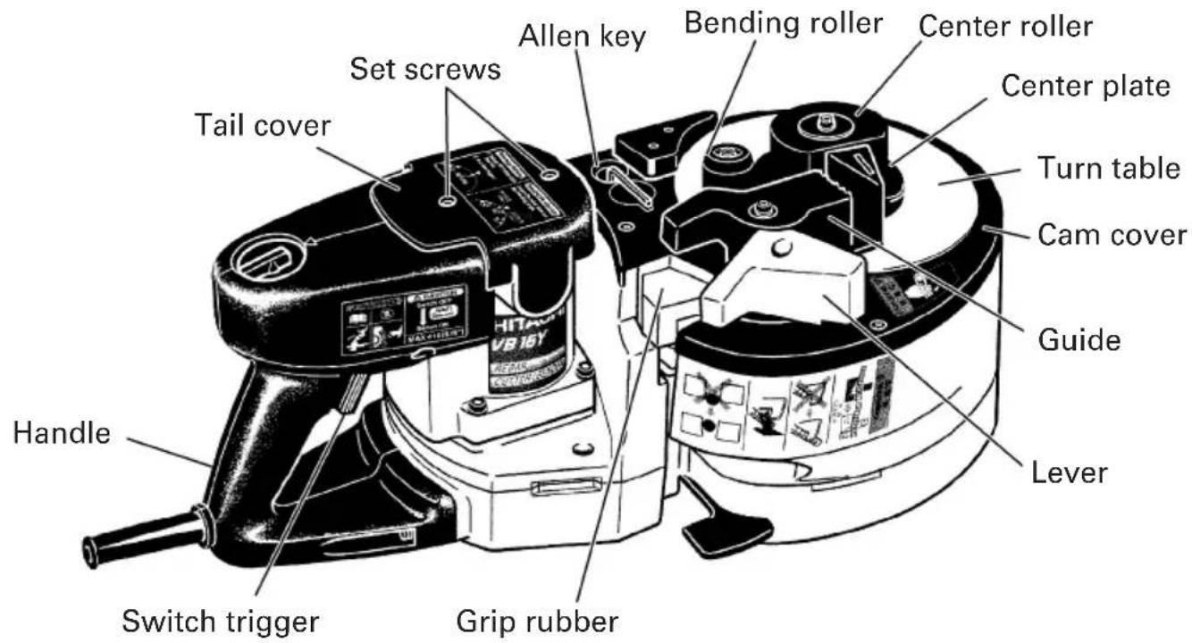
Fig. 1
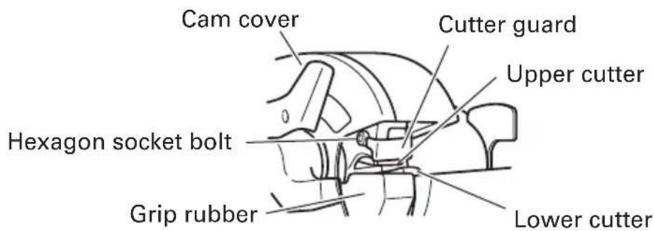
Fig. 2
When installing the deflection When folding the deflection guard guard
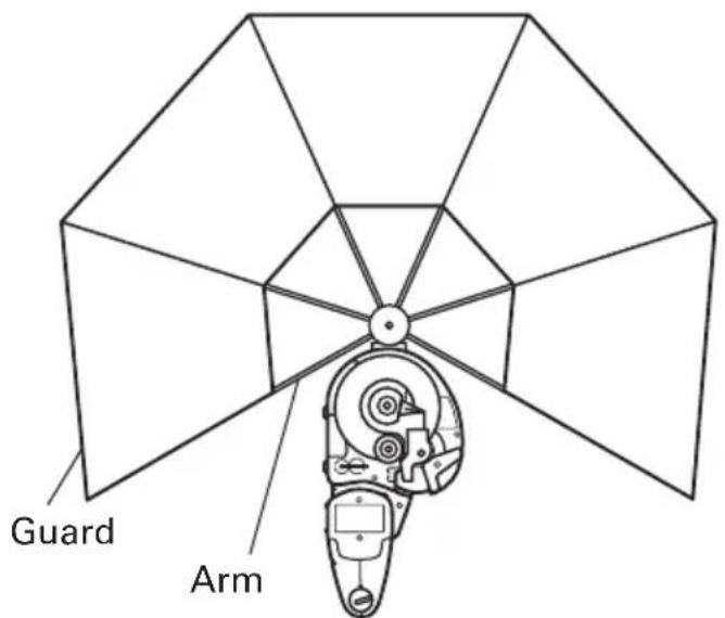
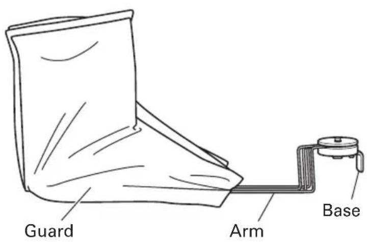
Fig. 3 Fig. 4
SPECIFICATIONS
| Motor Single-Phase, Series Commutator Motor | |
| Power Source Single-Phase, 120 V AC 60 Hz | |
| Current 8 A | |
| Capacities (1) Material: Concrete reinforcing bars only(for ASTM)GRADE 40, GRADE 60(2) Bar Designation Size#3, #4, #5 (3/8", 1/2", 5/8") | |
| Number of piece(s) that can be processed at one time | Cutting Bending |
| #3 (3/8")..... 2 pieces #3 (3/8") .... 3 pieces#4 (1/2")..... 1 piece #4 (1/2") .... 2 pieces#5 (5/8")..... 1 piece #5 (5/8") .... 1 piece | |
| No-Load Speed 0 – 16/min. | |
| Weight (without cord) 39.7 lbs (18.0 kg) | |
ASSEMBLY AND OPERATION
APPLICATIONS
○Cutting of rebar
○Bending of rebar
PRIOR TO OPERATION
1. Power source
Ensure that the power source to be utilized conforms to the power source requirements specified on the product nameplate.
Also, avoid using DC power or engine generators. Not only will the tool get damaged but an accident can result.
2. Power switch
Ensure that the switch is in the OFF position. If the plug is connected to a receptacle while the switch is in the ON position, the power tool will start operating immediately and can cause serious injury.
3. Extension cord
When the work area is far away from the power source, use an extension cord of sufficient thickness and rated capacity. The extension cord should be kept as short as practicable.
⚠ WARNING: Damaged cord must be replaced or repaired.
4. Check the receptacle
If the receptacle only loosely accepts the plug, the receptacle must be repaired. Contact a licensed electrician to make appropriate repairs.
If such a fautly receptacle is used, it may cause overheating, resulting in a serious hazard.
5. Confirming condition of the environment
Confirm that the work site is placed under appropriate conditions conforming to prescribed precautions.
- For safety sake, use the provided Allen key to make absolutely sure that the hexagon socket bolt is securely clamped. Use of the unit with the bolt in a loosely clamped condition can result in damage to the unit and cutter as well as accidents.
7. Confirm that the cutter is in sharp condition.
Make certain that the cutter is in a sharp condition. Continued use of a worn out and deformed cutter with dull edges results in damage to the unit and cutter as well as accidents.
PICTGRAPH ILLUSTRATION AND EXPLANATION
Read handling instructions before use.
Do not this electric power tools in wet wether conditions.
If the switch is turned off and then immediately turned on again, the motor may not start. Wait for at least one full second before attempting to turn the motor on again after it has been switched off.
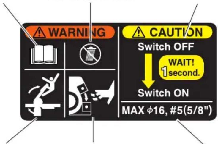
Begin operation only after ensuring that there are no people within the turning range of the material to be bent.
Never bring your hand close to the cutter during operation.
Avoid any work exceeding the maximum capacities. (Rebar diameter: #5 (5/8"))
(Returning Halfway)
①Select RETURN with the dial.
②Pull the trigger.

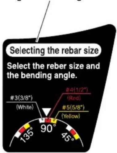
(Selecting the rebar size) Select the rebar size and the bending angle.

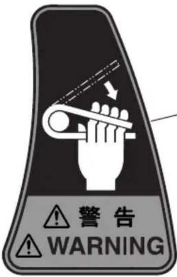
- If you bend the rebar with a large angle while placing your hand onto it, there is a fear of getting your hand caught in by the fold-back reaction of the rebar. Never place your hand onto the position where the rebar may fold back.
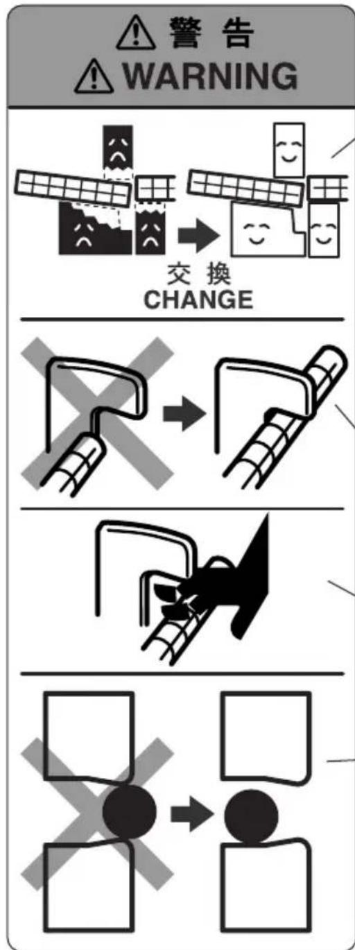
- The cutter blade can get worn out by repeated rebar cutting. Continued use of a worn-out cutter can result in the damage and the broken pieces flying around. Replace it with a new cutter after no more than 5,000 times of cutting.
- The machine is so designed that the upper cutter and the grip rubber can support a rebar. If the grip rubber gets worn out, there is a fear that it cannot sufficiently hold the rebar and gets broken down with its parts flying around, etc. If the grip rubber cannot hold the rebar much longer, replace it with a new grip rubber. Also replace the worn grip rubber with new one when replacing the cutter.
- During cutting work, securely hook the rebar to the reaction stopper B. Furthermore, secure enough length of a rebar to be hooked to the reaction stopper B.
- Avoid bringing your hand near to the reaction stopper B during operation. If you do so, you may get your finger caught in or may run the hazard of other injuries.
- Set the rebar in the center or the recess of the cutter during cutting work. Any cutting work with the rebar set on corners or ends of the cutter can result in the pieces of broken rebar flying around or the damage to the cutter and the machine.
HOW TO USE (CUTTING)
1. Normal cutting (Fig. 5)
(1) Turn the lever in the direction of the arrow mark and open the cover.
(2) Set the setting dial at the "cut" position. (Turn the setting dial all the way clockwise.) (Fig. 6)
(3) Set the unit in the position shown in Fig. 5.
(4) Set the rebar to be cut on the lower cutter.
(5) When the rebar is set, make sure that the reaction stopper B is hooked to the rebar.
(6) Pull the switch trigger and cut the rebar.
WARNING:
○While turning switches, never put your hand close to the cutter, reaction stopper, or bending roller.
○Bringing your hand close to these components can result in serious injury.
○Do not cut any rebar exceeding the maximum capacities of the unit described in the specifications.
Never cut any hard materials such as PC(Precast concrete) steel. Materials of this type are likely to scatter into pieces and cause injuries.
○The rebar you are cutting may have a hard spot in it. Quality may vary within each rebar. Do not attempt to cut NON-GRADE rebar.
○Replace the worn grip rubber with new one when replacing the cutter.
Note that the unit is not a hand held tool. Be absolutely sure to use the unit only after placing it on stable spots such as floor, ground, etc.
CAUTION:
Even after the cutting has been completed, continue pulling the switch trigger until the motor starts to run in the reverse direction and the cutter starts to return. If the switch trigger is released too early, the cutter will not return and the trigger will have to be pulled again.
2. Removing the rebar during cutting operation.
(Fig. 7)
If the switch trigger is released in the middle of cutting, the cutter can come to a stop at a halfway position, jumming the rebar in the unit.
When this occurs, you can either pull the switch trigger again and cut off the rebar, or you can free the rebar by bringing the upper cutter back up to the home position by carrying out the following procedure. (Fig. 7)
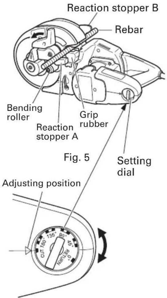
Fig. 6
natural_image
Mechanical diagram showing a lever mechanism with rotational arrows indicating motion (no text or symbols)Fig. 7
○Removing (Fig. 8)
Set the setting dial to the "RETURN" position as shown in Fig. 8 and pull the switch trigger again.

Fig. 8
SERVICE LIFE AND REPLACEMENT OF THE CUTTER
- Service life of cutter (Fig. 9)
Repeated cutting of the rebar can result in the "wear and tear", "deformation", "nicked edges", etc. Using the cutter under such circumstances will not only damage the machine but also there will be a fear of the broken cutter fragments flying around.
Replace it with a new cutter after cutting no more than 5,000 pieces of rebar.
- Before removing the cutter
(1) Pull the switch lightly and let the upper cutter move slowly. When the hexagon socket bolt that fixes the upper cutter comes out of the cam cover, turn the switch OFF and stop the motor.
(2) Unplug the power cord from the receptacle.
- Removal
○If you remove the hexagon socket bolt using the provided Allen key, you can remove the cutter. (Pushing the cutter guard up in the direction of the arrow shown in Fig. 10, facilitates removal of the upper cutter.)
○Removal of the lower cutter can be easily made if the lower cutter is wrenched with a Phillips head screwdriver as shown in the following diagram. (Fig. 11)
Blade
natural_image
Simple line drawing of a rectangular box with two circular cutouts and a diagonal line extending upward (no text or symbols)Fig. 9
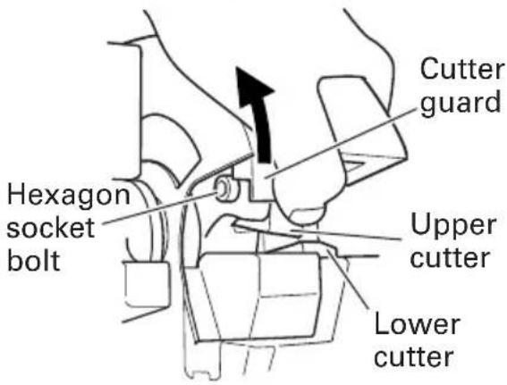
Fig. 10
WARNING:
To prevent accidents, always be sure to turn the switch OFF and unplug the power cord from the receptacle.
If you remove the hexagon socket bolt using the provided Allen key, you can remove the cutter. (Pushing the cutter guard up in the direction of the arrow shown in Fig. 10, facilitates removal of the upper cutter.)
natural_image
Technical line drawing of a mechanical assembly with no visible text or symbolsFig. 11
4. Mounting
(1) Get rid of dust around the cutter installing section and clean it up.
(2) Align the hole of a new cutter and the position of a pin, and insert into the installing section.
(3) Also replace the hexagon socket bolt (packed along with the cutter) with a new one simultaneously, completely tighten it using the attached Allen key, and then fix the cutter.
CAUTION:
●Install the cutter and accessories securely according to the instruction manual. If you fail to install them properly, they may come off and cause an injury.
●Be sure to unplug the power cord from the receptacle when the cutter is checked, cleaned, and replaced. Failure to do so can result in a serious injury.
HOW TO USE (BENDING)
- Setting bending angles by setting dial
The bar can be bent according to the angles indicated on the setting dial, as shown in Fig. 12.
| Dial indication 45° | 90° 135° 180° | |||
| Condition of rebar | 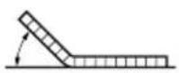 | 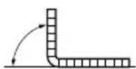 | 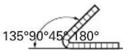 | 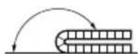 |
Fig. 12
In bending the rebar of #3(3/8"), #4(1/2"), and #5(5/8") diameters, a difference takes place in the bending angle even in the same dial position depending upon the difference of rebar's thickness. Slightly change a position of the setting dial depending upon the rebar's diameter even with the same bending angle as shown in Fig. 13.
Adjusting position
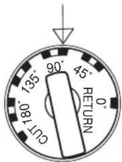
Fig. 13
| Size of rebar Colors of indicated marks | |
| #3(3/8") White | |
| #4(1/2") Red | |
| #5(5/8") Yellow | |
NOTE: Even at the same dial setting position, the bending angle can sometimes differ if the diameter or hardness of the rebar is different. Use the angle marks merely as a rough guideline.
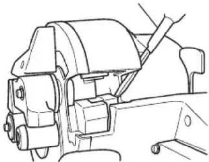
2. Ordinary bending
(1) Set the unit in the position with the turntable up as shown in Fig. 14.
(2) Make sure that the cover is closed.
(3) Set the setting dial at the desired angle. (Fig. 13)
(4) Place the rebar on the center plate and set it correctly as shown in Fig. 14.
(5) Pull the switch trigger and bent the rebar.
(6) Continue pulling the switch trigger until the motor makes reverse rotation and the bending roller starts to return. (Once the bending roller starts to return, it will automatically return all the way to the home position even if the switch trigger is released.) (Fig. 15)
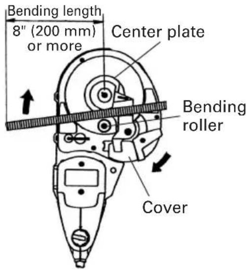
Fig. 14
WARNING:
Make absolutely sure that the cutter cover is closed when you don't carry out the cutting work. If the cover is kept open, the cutter can jam on foreign objects and cause serious accidents. (Fig. 16)
○Never bring your hand close to the bending roller during operation.
○If you bend the rebar with a large angle while placing your hand onto it, there is a fear of getting your hand caught in by the fold-back reaction of the rebar. Never place your hand onto the position where the rebar may fold back.
○Do not bend any rebar exceeding the maximum capacities of the unit described in the specifications. Never bend any hard materials such as PC(Precast concrete) steel. Materials of this type are likely to scatter into pieces and cause injuries.
○The rebar you are bending may have a hard spot in it. Quality may vary within each bar. Do not attempt to bend NON-GRADE Rebar.
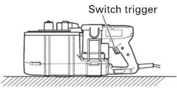
Fig. 15
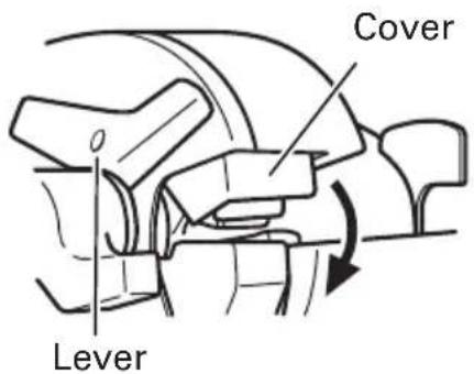
Fig. 16
Never place your hand onto the bending side of the rebar. If you do so, your hand may be caught in the mechanical parts.
○ Install the deflection guard for operation with the bending length of a rebar 20" (inside dimension of the deflection guard) or less to protect the persons around the rebar cutter/bender in case rebar splinters into pieces and deflects during bending. (Fig. 21)
○Remove the deflection guard when bending a rebar whose bending length and the fixed length are more than 20" to prevent damage to the deflection guard.
○Replace the deflection guard with new one if it is damaged. Damaged deflection guard cannot protect the persons around the rebar cutter/bender in case a rebar splinters into pieces and deflects during bending.
○Note that the unit is not a hand-held tool. Be absolutely sure to use the unit only after placing it on a stable spots such as floor, ground, etc.
○Begin operation only after marking sure that there are no people within the turning range of the material to be bent.
○The minimum required bending length is 8" (200 mm).
If the bending length is not long enough, the rebar can come off during bending operation, or it can break into fragments and scatter dangerously. (Fig. 14)
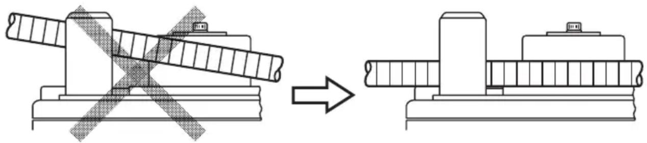
Place the rebar on the center plate and set it so that it is horizontal with the turntable surface.
If the side that is to be bent is set inclined upward, the rebar can come loose from the bending roller while bending causing it to fly off. (Fig. 17)
natural_image
Technical line drawing showing a mechanical assembly before and after modification, with no visible text or symbols.Fig. 17
When bending multiple rebars at one time, some may come off the bending roller and guide, etc., and therefore exercise caution and set them horizontally.
○Bend less than every 3 pieces of rebar with a #3(3/8") diameter, less than every 2 pieces with a #4(1/2") diameter, and every 1 piece with a #5(5/8") diameter.
Remember that the cutter moves even during the bending operation, thereby, close the cutter cover without fail.
3. How to install deflection guard
The deflection guard is provided to protect the persons around the rebar cutter/bender in case a rebar splinters into pieces and deflects during bending. Install the deflection guard to the VB16Y for operation with the bending length of a rebar 20" (inside dimension of the deflection guard) or less.
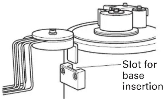
Fig. 18
(1) Insert the base of the deflection guard into the slot of the rebar cutter/bender. (Fig. 18)
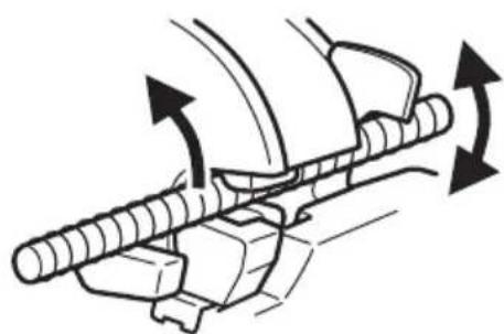
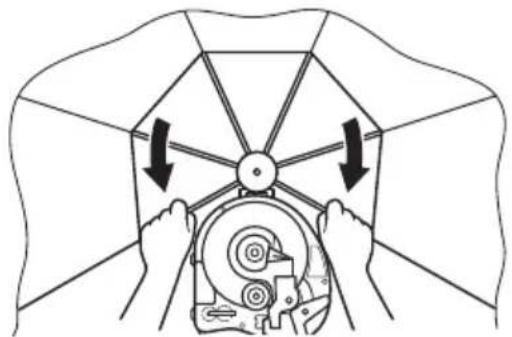
(2) Open the guard fully by pulling the arms as shown below until a click is heard. (Fig. 19)
- How to remove deflection guard
○Reverse the installation procedure to remove the deflection guard.
- How to use deflection guard
(1) Be sure to install the deflection guard when bending a rebar whose bending length and the fixed length are 20" (inside dimensin of deflection guard) or less (Fig. 20)
natural_image
Diagram of hands operating a mechanical device with arrows indicating rotation or force direction (no text or symbols)Fig. 19
(2) Be sure to install the deflection guard when bending a rebar whose bending length is 20" (inside dimensin of deflection guard) or less and the fixed length is more than 20". In this case, move the arm at the fixed end. (Fig. 21)
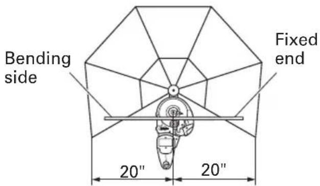
Fig. 20 Fig. 21
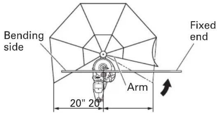
(3) Remove the deflection guard when bending a rebar whose bending length and the fixed length are more than 20" (inside dimension of the deflection guard).
CAUTION:
●Set a rebar on the rebar cutter/bender so that the bending length is equal to or shorter than the fixed length.
- Bending by eye measurement
Since the unit uses a variable-speed switch, you can bend the rebar to your desired angle by eye measurement in addition to the dial setting.
(1) Set the setting dial to a larger angle than you desire.
(2) Pull the switch trigger lightly and bend the rebar slowly.
(3) When the rebar is bent to the desired angle, stop pulling the switch. If the bar is still small of the desired angle, pull the switch again.
(4) Remove the rebar after bending has been finished. Then, pull the switch once more and return the bending roller to the home position. (Continue pulling the switch until the bending roller begins reverse rotation.)
-
Removing rebar during bending operation When bending out at a low speed in "bending by eye measurement", the rebar can sometimes get caught in the bending roller due to its own flexure. If this occurs, you can return the bending roller to the home position by pulling the switch again after setting the setting dial to the "return" position. This is the same method used to remove the rebar when it gets caught during cutting operation. (Fig. 22)
-
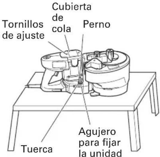
Using hole to fix unit in place A hole is provided at the center of the unit to fix and stabilize it. This hole comes in quite handy when used in the following manner. (Fig. 23) ○For bending operation when the unit is fixed to a work bench.
This hole will prove very convenient when the unit is bolted to a suitable work bench. (Bolt size M10, less than W3/8.)
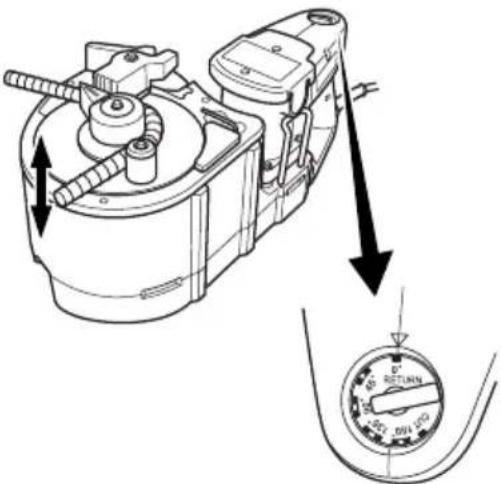
Fig. 22
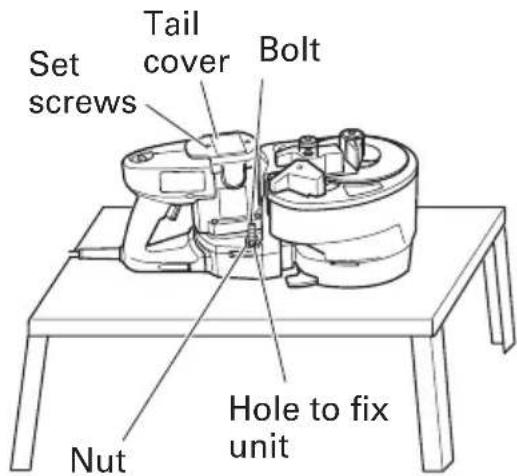
Fig. 23
MAINTENANCE AND INSPECTION
⚠ WARNING: Be sure to switch power OFF and disconnect the plug from the receptacle during maintenance and inspection.
1. Inspecting the cutter
Continued use of a dull or damaged cutter will result in reduced cutting efficiency and may cause overloading of the motor. Replace the cutter with a new one as soon as excessive abrasion is noted.
2. Inspecting the mounting screws
Regularly inspect all mounting screws and ensure that they are properly tightened. Should any of the screws be loosened, retighten them immediately.
⚠ WARNING: Using this Reber cutter/bender with loosened screws is extremely dangerous.
3. Maintenance of the motor
The motor unit winding is the very "heart" of the power tool. Exercise due care to ensure the winding does not become damaged and/or wet with oil or water.
4. Inspecting the carbon brushes (Fig. 24)
The Motor employs carbon brushes which are consumable parts. When they become worn to or near the “wear limit”, it could result in motor trouble. When an auto-stop carbon brush is equipped, the motor will stop automatically. At that time, replace both carbon brushes with new ones which have the same carbon brush Numbers shown in the figure. In addition, always keep carbon brushes clean and ensure that they slide freely within the brush holders.
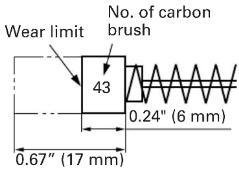
Fig. 24
NOTE: Use HITACHI carbon brush No. 43 indicated in Fig. 24.
5. Replacing carbon brushes
Loosen the set screws and remove the tail cover. Remove the brush caps and carbon brushes. After replacing the carbon brushes, do not forget to tighten the brush caps securely and to mount the tail cover with set screws.
6. Service and repairs
All quality power tools will eventually require servicing or replacement of parts because of wear from normal use. To assure that only authorized replacement parts will be used, all service and repairs must be performed by a HITACHI AUTHORIZED SERVICE CENTER, ONLY.
ACCESSORIES
WARNING: Accessories for this power tool are mentioned in this Instruction Manual. The use of any other attachment or accessory can be dangerous and could cause injury or mechanical damage.
NOTE: Accessories are subject to change without any obligation on the part of the HITACHI.
STANDARD ACCESSORIES
(1) Allen wrench (For M5 hexagon socket bolt) 1 (attached to unit)
(2) One set of cutters .... 1 (attached to unit)
(3) Deflection guard .... 1
OPTIONAL ACCESSORIES......sold separately
⚠ WARNING: Do not bend the rebar with #5 (5/8" in diameter) using the center roller set (D38) and center roller set (D50).
Otherwise, there is a fear that the rebar may snap.
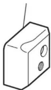
(1) Cutter (Fig. 25)(Code No. 319706) * One set containing two pieces
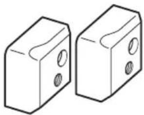
natural_image
Two 3D block diagrams with circular holes, no text or symbols presentFig. 25
(2) Center Roller (D 50) Set (Fig. 26)(Code No. 321446)
* This is used when the bending diameter of a rebar is changed to (bent diameter: 50 mm).
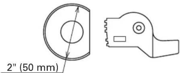
Fig. 26
(3) Center Roller (D 38) Set (Fig. 26)(Code No. 321445) * This is used when the bending diameter of a rebar is changed to (bent diameter: ∅38 mm).
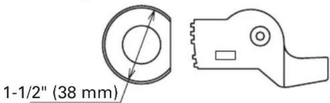
Fig. 27
NOTE: Specifications are subject to change without any obligation on the part of the HITACHI.
INFORMATIONS IMPORTANTES
Fig. 4
SPECIFICATIONS
radar
| Rebar Size | Bending Angle | |------------|---------------| | #3(3/8") | White | | #4(1/2") | Red | | #5(5/8") | Yellow |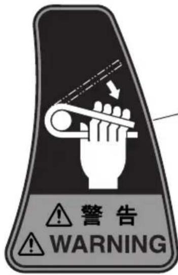
natural_image
Diagram showing a mechanical component before and after modification, with no visible text or symbols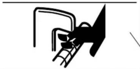
natural_image
Pure electrical circuit lines without any symbols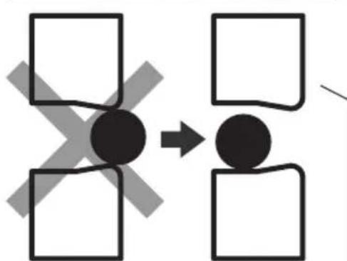
flowchart
graph TD
    A["Black Circle"] --> B["White Square"]
    A --> C["White Square"]
    A --> D["White Square"]
    A --> E["White Square"]
    A --> F["White Square"]
    style A fill:#000,stroke:#000,color:#fff
    style B fill:#000,stroke:#000,color:#fff
    style C fill:#000,stroke:#000,color:#fff
    style D fill:#000,stroke:#000,color:#fff
    style E fill:#000,stroke:#000,color:#fff
    style F fill:#000,stroke:#000,color:#fff
natural_image
Mechanical diagram showing a bolt and connecting rod with directional arrows indicating motion (no text or symbols)Fig. 7
natural_image
Technical line drawing of a mechanical assembly with no visible text or symbolsFig. 11
natural_image
Technical line drawing showing a mechanical assembly before and after modification, with no visible text or symbols.Fig. 17
natural_image
Diagram of hands operating a mechanical device with arrows indicating rotation or force direction (no text or symbols)Fig. 19
natural_image
Two 3D block diagrams with circular holes, no text or symbols presentFig. 25
(2) Ensemble de rouleau central (D 50)(Fig. 26)(No. de code 321446)
natural_image
Simple line drawing of a mechanical component with no text or symbols2" (50 mm)
Fig. 26
(3) Ensemble de rouleau central (D 38)(Fig. 27)(No. de code 321445)
Fig. 27
gauge
Selecting the rebar size | Label | Value | |---|---| | #3(3/8") (White) | 90 | | #4(1/2") (Red) | 90 | | #5(5/8") (Yellow) | 90 | | 135° | 45° |
natural_image
Mechanical diagram showing a lever mechanism with rotating arrows indicating motion (no text or symbols)Fig. 7
natural_image
Technical line drawing of a mechanical assembly with no visible text or symbolsFig. 11
ADVERTENCIA:
NOTAS SOBRE EL USO (CURVADORA)
natural_image
Technical line drawing showing a mechanical assembly before and after modification, with no visible text or symbols.Fig. 17
natural_image
Diagram of hands operating a mechanical device with arrows indicating rotation or force direction (no text or symbols)Fig. 19

Fig. 22
natural_image
Two 3D block diagrams with circular holes, no text or symbols presentFig. 25
Fig. 26
Fig. 27
Minato-ku, Tokyo 108-6020, Japan
Distributed by

Hitachi Koki U.S.A., Ltd.
3950 Steve Reynolds Blvd.
Norcross, GA 30093

Hitachi Koki Canada Co.
6395 Kestrel Road
Mississauga ON L5T 1Z5

- SAFETY INSTRUCTIONS AND INSTRUCTION MANUAL
- WARNING
- INSTRUCTIONS DE SECURITE ET MODE D'EMPLOI
- AVERTISSEMENT
- TABLE DES MATIERES
- Français
- MEANINGS OF SIGNAL WORDS
- SAFETY
- IMPORTANT SAFETY INSTRUCTIONS FOR USING ALL POWER TOOLS
- SPECIFIC SAFETY RULES AND SYMBOLS
- WARNING: For Your Own Safety Read Instruction Manual Before Operating Tool.
- REPLACEMENT PARTS
- USE PROPER EXTENSION CORD
- WARNING: Avoid electrical shock hazard. Never use this tool with a damaged or frayed electrical cord or extension cord.
- SAVE THESE INSTRUCTIONS AND MAKE THEM AVAILABLE TO OTHER USERS OF THIS TOOL!
- FUNCTIONAL DESCRIPTION
- NAME OF PARTS
- ASSEMBLY AND OPERATION
- APPLICATIONS
- PRIOR TO OPERATION
- Power source
- Power switch
- Extension cord
- ⚠ WARNING: Damaged cord must be replaced or repaired.
- Check the receptacle
- Confirming condition of the environment
- Confirm that the cutter is in sharp condition.
- PICTGRAPH ILLUSTRATION AND EXPLANATION
- HOW TO USE (CUTTING)
- Normal cutting (Fig. 5)
- WARNING:
- CAUTION:
- Removing the rebar during cutting operation.
- SERVICE LIFE AND REPLACEMENT OF THE CUTTER
- Mounting
- HOW TO USE (BENDING)
- Ordinary bending
- How to install deflection guard
- MAINTENANCE AND INSPECTION
- ⚠ WARNING: Be sure to switch power OFF and disconnect the plug from the receptacle during maintenance and inspection.
- Inspecting the cutter
- Inspecting the mounting screws
- ⚠ WARNING: Using this Reber cutter/bender with loosened screws is extremely dangerous.
- Maintenance of the motor
- Inspecting the carbon brushes (Fig. 24)
- Replacing carbon brushes
- Service and repairs
- ACCESSORIES
- STANDARD ACCESSORIES
- OPTIONAL ACCESSORIES......sold separately
- INFORMATIONS IMPORTANTES
- ADVERTENCIA:
- NOTAS SOBRE EL USO (CURVADORA)
- Hitachi Koki U.S.A., Ltd.
- Hitachi Koki Canada Co.
Brand : HITACHI
Model : VB16Y
Category : Grinder