
CWBP-6 - Refrigerator Hatco - Free user manual and instructions
Find the device manual for free CWBP-6 Hatco in PDF.

| Product Type | Instantaneous Recirculating Gas Water Heater |
| Model | CWBP-6 (equivalent PMG-100/200) |
| Heating Capacity | Input: 105,000 BTU/h (PMG-100) / 195,000 BTU/h (PMG-200); Output: 84,800 BTU/h (PMG-100) / 156,000 BTU/h (PMG-200) |
| Water Flow (22°C rise) | 912 L/h (PMG-100) / 1711 L/h (PMG-200) |
| Fuel | Natural gas or propane (LP) |
| Inlet Gas Pressure | Natural gas: 5-10.5 inches WC; Propane: 11-13 inches WC |
| Electrical Supply | 120 VAC, 15 A, single-phase, 60 Hz |
| Dimensions (L x W x H) | See Technical Drawing (PMG models) |
| Dry Weight | 82 kg (PMG-100) / 98 kg (PMG-200) |
| Outlet Temperature | 82°C (180°F) adjustable; factory set at 88°C (190°F) |
| Water Service Pressure | Maximum 150 psi; safety relief valve at 150 psi / 99°C |
| Tank Material | Stainless steel |
| Ignition | Electronic with automatic pilot |
| Controls | Electronic thermostat with probe; on/off switch |
| Safety | Temperature/pressure safety relief valve; high-temperature limit on tank and heat exchanger; low water cutoff; pressure switch |
| Circulation Pump | Recirculation pump with bronze body |
| Connections | Gas: 3/4" NPT; Water: 3/4" NPT; Electrical: 120 VAC |
| Venting | Forced draft system; 4" vent adapter (straight or 90°) |
| Included Accessories | Pressure regulator with bypass, temperature/pressure gauges (x2), phosphate water treatment system, water hammer arrester, gas shut-off valve |
| Maintenance | Heat exchanger flush, water treatment cartridge replacement, burner inspection, regular cleaning |
| Warranty | 1 year parts and labor + 9 years parts on tank |
Frequently Asked Questions - CWBP-6 Hatco
User questions about CWBP-6 Hatco
0 question about this device. Answer the ones you know or ask your own.
Ask a new question about this device
Download the instructions for your Refrigerator in PDF format for free! Find your manual CWBP-6 - Hatco and take your electronic device back in hand. On this page are published all the documents necessary for the use of your device. CWBP-6 by Hatco.
USER MANUAL CWBP-6 Hatco
Register Online! (see page 2)
WARNING! If the information in these instructions is not followed exactly, fire or explosion may result causing property damage, personal injury, or death.
— Do not store or use gasoline or other flammable vapors and liquids in the vicinity of this or any other appliance.
— WHAT TO DO IF YOU SMELL GA\$
- Do not try to light any appliance.
- Do not touch any electrical switch; do not use any phone in your building.
- Immediately call your gas supplier from a neighbor's phone. Follow the gas supplier's instructions.
- If you cannot reach your gas supplier, call the fire department.
- Do not return to your building until authorized by the gas supplier or fire department.
—Installation and service must be performed by a qualified installer, service agency, or the gas supplier.
Water Heaters for other than recreational vehicle installation only.
NOTE: Keep this manual in a safe location for future reference.
Important Owner Information....2
Introduction......2
Important Safety Information....3
Model Description 5
System Overview....6
Specifications....6
General 6
Water Temperature Recovery Table 7
Dimensions....7
Installation....8
General 8
Minimum Clearance Requirements 9
Plumbing Installation 11
Gas Installation....15
Electrical Installation....16
Venting Installation 17
Operation....19
General 19
Maintenance....20
General 20
Burner Removal/Inspection 21
Draining the Heat Exchanger 21
Component Adjustments/Replacements ....21
Limited Warranty 24
Wiring Diagram....25
Replacement Parts List....26
Authorized Parts Distributors ....Back Cover
IMPORTANT OWNER INFORMATION
Record the model number, serial number, voltage, and purchase date of the unit in the spaces below (specification label located on the lower front, right-hand corner of the unit). Please have this information available when calling Hatco® for service assistance.
Model No. ____
Serial No.
Voltage
Date of Purchase
Register your unit!
: Completing online warranty registration will prevent delay in obtaining warranty coverage. Access the Hatco website at www.hatcocorp.com, select the Support pull-down menu, and click on "Warranty".
Business
Hours: 7:00 AM to 5:00 PM Monday–Friday,
Central Time (CT)
(Summer Hours: June to September—
7:00 AM to 5:00 PM Monday–Thursday
7:00 AM to 4:00 PM Friday)
Telephone: 414-671-6350
E-mail: support@hatcocorp.com

24 Hour 7 Day Parts and Service
Assistance available in the United States
and Canada by calling 414-671-6350.
Additional information can be found by visiting our web site at www.hatcocorp.com
INTRODUCTION
Hatco Powermite ^® Gas Booster Water Heaters are instantaneous, fin tube type water heaters designed for use with commercial dish machines to boost the temperature of the regularly available hot water, usually 115°–150°F (46°–66°C) up to 180°F (82°C). Water at 180°F (82°C) can be used as sanitizing rinse water in commercial dish machines in accordance with Health Codes, NSF Standard #5 and plumbing codes.
Hatco Gas Booster Water Heaters are design certified by CSA International and tested under the requirements of the American National Standard, ANS Z21.10.3*CSA 4.3, Current Edition.
All Hatco Gas Booster Water Heaters are factory pre-plumbed and pre-wired for easy installation. The control compartment area is accessible from the front, which permits easy installation, even when near other equipment.
All Hatco Gas Booster Water Heaters are warranted to be free of defects in material and workmanship under normal use and service, when installed in accordance with factory recommendations. Dependability of the Booster Water Heater is preserved through proper, safe installation and operation.
Hatco Gas Booster Water Heaters are products of extensive research and field testing. The materials used were selected for maximum durability, attractive appearance, and optimum performance. Every unit is inspected and tested thoroughly prior to shipment.
This manual provides the installation, safety, and operating instructions for Powermite Gas Booster Water Heaters. Hatco recommends all installation, operating, and safety instructions appearing in this manual be read prior to installation or operation of a unit.
Safety information that appears in this manual is identified by the following signal word panels:

WARNING indicates a hazardous situation which, if not avoided, could result in death or serious injury.

CAUTION indicates a hazardous situation which, if not avoided, could result in minor or moderate injury.

NOTICE is used to address practices not related to personal injury.

Read the following important safety information before using this equipment to avoid serious injury or death and to avoid damage to equipment or property.
WARNING
FIRE OR EXPLOSION HAZARD:
- Unit must be installed by qualified, trained installers. Installation must conform to all local plumbing and gasfitting codes. Installation by unqualified personnel will void the unit warranty and may lead to fire or explosion causing property damage, personal injury, or death. Check with local plumbing inspectors for proper procedures and codes.
- Do not store or use gasoline or other flammable vapors or liquids in the vicinity of this or any other appliance.
- The gas used with this unit must be the type specified on the spec plate on this unit. To avoid personal injury or damage to the unit, never use any other than the specified gas.
- The heater and its gas connection must be leak tested before placing the Booster Water Heater in operation. Use soapy water or commercially available fluid for leak test. DO NOT use open flame to test for leaks.
- The Booster Water Heater and its individual shut-off valve must be disconnected and isolated from the gas supply piping system during any pressure testing of the system at test pressures in excess of 1/2 psi (3.5 kPa.).
- This appliance must be isolated from the gas supply piping system by closing its individual manual shutoff valve during any pressure testing of the gas supply piping system at test pressures equal to or less than 1/2 psig (3.5 kPa).
- Dissipate test pressure from the gas supply line before re-connecting the heater and its manual shut-off cock to the gas supply line. Failure to follow this procedure may damage the gas valve. Over-pressurized gas valves are not covered by the warranty.
- If the information in these instructions is not followed exactly, fire or explosion may result causing property damage, personal injury, or death
ELECTRIC SHOCK HAZARD:
- Unit must be installed by qualified, trained installers. Installation must conform to all local electrical codes. Installation by unqualified personnel will void the unit warranty and may lead to electric shock or burn, as well as damage to unit and/or its surroundings. Check with local electrical inspectors for proper procedures and codes.
- Unit is not weatherproof. Locate unit indoors where ambient air temperature is a minimum of 70^ (21°C).
- If an external electrical source is utilized, the appliance, when installed, must be electrically grounded in accordance with local codes, or, in the absence of local codes, with the National Electrical Code, ANSI/NFPA 70, and CSA C22.1, Electrical Code.
- Do not place aftermarket covers on or over Booster Water Heater. Doing so can cause temperature and moisture build-up resulting in premature failure and electrical shock.
WARNING
ELECTRIC SHOCK HAZARD: Use only Genuine Hatco Replacement Parts when service is required. Failure to use Genuine Hatco Replacement Parts will void all warranties and may subject operators of the equipment to hazardous electrical voltage, resulting in electrical shock or burn. Genuine Hatco Replacement Parts are specified to operate safely in the environments in which they are used. Some aftermarket or generic replacement parts do not have the characteristics that will allow them to operate safely in Hatco equipment.
This unit must be serviced by qualified personnel only. Service by unqualified personnel may lead to fire, explosion, electric shock, or burn.
ALWAYS turn OFF power at fused disconnect switch/circuit breaker, shut off gas supply, and allow unit to cool before performing any cleaning, adjustments, or maintenance.
Temperature/pressure protective equipment should not be less than a combination temperature/pressure relief valve certified by a nationally recognized testing laboratory that maintains periodic inspection of the production of this equipment and meets the requirements for Relief Valves and Automatic Shutoff Devices for Hot Water Supply Systems, CSA ANSI Z21.22 /CSA 4.4. The temperature/pressure relief valve must be marked with a minimum set pressure not to exceed the marked hydrostatic test pressure of the Booster Water Heater as noted on the unit specifications.
FOR INSTALLING PRESSURE AND TEMPERATURE RELIEF VALVES IN ACCORDANCE WITH CSA ANSI Z21.22/CSA 4.4. Combination pressure and temperature relief valves with extension thermostats must be installed so that the temperature-sensing element is immersed in the water within the top 6" (152 mm) of the tank. They must be installed directly in a tank tapping. Combination pressure and temperature relief valves that do not have extension elements must be mounted directly in a tank tapping located within the top 6" (152 mm) of the tank, and shall be adequately insulated and located so as to assure isolation from ambient conditions that are not indicative of stored water temperature. TO AVOID WATER DAMAGE OR SCALDING DUE TO VALVE OPERATION, DRAIN PIPE MUST BE CONNECTED TO VALVE OUTLET AND RUN TO A SAFE PLACE OF DISPOSAL. Discharge line must be as short as possible and be the same size as the valve discharge connection throughout its entire length. Drain line must pitch downward from the valve and must terminate between 1-1/2" (38 mm) and 6" (152 mm) above the floor drain where any discharge will be clearly visible. The drain line shall terminate plain, not threaded, with material serviceable for temperatures up to 250°F (121°C) or greater. Excessive length, over 30' (9.1 m), or use of more than four elbows can cause a restriction and reduce the discharge capacity of the valve. No shut-off valve shall be installed between the relief valve and tank, or in the drain line. Valve lever must be tripped periodically to assure that waterways are clear. This device is designated for emergency safety relief and shall not be used as an operating control. The valves are set to relieve at 150 psi (1034 kPa) or when water temperature reaches 210°F (99°C). Read tag on valve for additional information.
WARNING
Should overheating occur or the gas supply fail to shut off, turn off the manual gas control valve to the appliance.
Use only copper plumbing material. Non-copper plumbing material may create an unsafe condition.
Units are equipped with a high temperature limit safety switch that will shut off the power if the unit overheats. Contact an Authorized Hatco® Service Agent if the high temperature limit safety switch cannot be reset or continues to trip.
Before performing any maintenance/service, care should be taken that any of the discharged water does not come into contact with the operator or surrounding surfaces. Water can be extremely hot and can cause severe scalding and damage to the property.
If relief valve discharges periodically, do not plug valve. If replacing valve does not stop discharge, contact an Authorized Hatco Service Agent or the Hatco Service Department.
Install booster water heater in a horizontal position with the base parallel to the floor and the inlet connection at the lowest point. Improper installation could create an unsafe condition.
Do not connect booster water heaters to domestic (consumer) dish machines or other domestic utilized equipment. This booster may damage domestic equipment.
This product contains fiberglass, a product known to the state of California to cause cancer, birth defects, or other reproductive harm.
Install booster water heater as close as possible to a commercial dish machine. Employ re-circulation if distance between water heater and dish machine exceeds NSF specifications of five (5) linear feet (1524 mm).
It is essential to recognize that even though a water heater may be properly installed initially and approved, there always exists the possibility that unknowing individuals might alter or change the installation in a manner that would render it unsafe. Therefore, it is important that all safety programs provide some mechanism to assure that these installations are inspected periodically.
This unit has no "user-serviceable" parts. If service is required on this unit, contact an Authorized Hatco Service Agent or contact the Hatco Service Department at 414-671-6350.
CAUTION
BURN HAZARD:
• Water in unit is very hot. Wear protective gloves and proper attire when operating to avoid injury.
- Valves supplied by Hatco are designed for high temperature commercial operation. Do not substitute Hatco valves with valves designed for domestic water heaters.
Do not use anti-siphon valves or check valves on incoming water line. Damages caused by the use of these valves on unit will not be covered by warranty.
Do not connect Booster Water Heater directly to a boiler or furnace coil or any other uncontrolled temperature source. The Booster Water Heater thermostat could be damaged causing unit to overheat.
Incoming water temperature should be minimum of 85^ F ( 29^ C). Damage to the heater can occur if water is cooler than 85^ F ( 29^ C).
Do not connect an expansion tank of any type to Booster Water Heater water lines.
Label all wires prior to disconnection when servicing controls. Wiring errors can cause improper and dangerous operation. Verify proper operation after servicing.
Hatco requires that two temperature/pressure gauges (Hatco P/N 03.01.003.00) be installed to ensure proper operation. Install one in the supply line before the pressure reducing valve and one in the outlet line as close to the Booster Water Heater as possible. This provides a visual check of the water temperature and pressure before and after the water heater.
DO NOT turn on power to the Booster Water Heater until tank has been filled with water and all air has been vented through the dish machine rinse nozzles. Heating elements will burn out in seconds if operated when not immersed in water.
To avoid freezing water damage to the Booster Water Heater when the outside temperature is below 32^ F ( 0^ C), the unit must be left ON and the venting must be protected from migrating cold air.
Failure to drain the heat exchanger prior to exposing it to freezing conditions will damage the heat exchanger and void the warranty.
The use of cellular core PVC (ASTM F891), cellular core CPVC, or Radel® (polyphenylsulfone) in nonmetallic venting systems is prohibited. Covering non-metallic vent pipe and fittings with thermal insulation is also prohibited.
Using or storing chlorine based products on or near the Booster Water Heater may shorten the life of the unit and void the product warranty.
NOTICE
If water supply pressure to the booster inlet is over 20 psi (138 kPa) during flow, install pressure reducing valve with built-in bypass (Hatco P/N 03.02.004.00) for proper operation of dish machine rinse nozzles.
NOTE: The pressure reducing valve must be the type equipped with a high pressure bypass, as supplied by Hatco.
NOTICE
Incoming water supply to Booster Water Heater must be a minimum of 20 psi (1.4 kg/cm2). Water pressure less than 20 psi (1.4 kg/cm2) will decrease operating life of recirculating pump and unit.
NOTE: Product failure caused by incoming water pressure less than 20 psi (1.4 kg/cm2) is not covered under warranty.
Always drain Booster Water Heater with power to the unit off or element burnout could occur.
Use dielectric couplings when connecting dissimilar metals, such as galvanized to copper. This will prevent electrolysis or premature plumbing damage.
Do not back out or loosen any pipe fittings or leaks may occur.
Do not lay unit on the side with the control panel or inlet and outlet pipes. Damage to the unit could occur.
NOTICE
Incoming water in excess of 3 grains of hardness per gallon (GPG) (0.75 grains of hardness per liter [GPL]) must be treated and softened before being supplied to Booster Water Heater(s). Water containing over 3 GPG (0.75 GPL) will decrease efficiency, increase energy use, and reduce the operating life of the unit through increased lime build-up. Product failure caused by liming or sediment buildup is not covered under warranty.
Units are voltage-specific. Refer to specification label for electrical requirements before beginning installation. Connecting unit to incorrect power supply will void product warranty and may damage unit.
MODEL DESCRIPTION
All Models
Hatco Gas Booster Water Heaters are available in two models: PMG-100 and PMG-200. All standard models include a Booster Water Heater with a stainless steel tank, low-water cut-off system, temperature/pressure relief valve, pressure reducing valve with built-in high pressure bypass, two temperature/pressure gauges, blended phosphate water treatment system, shock absorber, gas shut-off valve, 4" (102 mm) flue adapters (straight and 90°), and a high temperature limit safety switch.
Model PMG-100
Model PMG-100 features three tube-type burners, a Power I/O (on/off) switch, indicator lights, and 6" (152 mm) legs. PMG-100 units provide up to 241 gallons per hour (GPH) (912 liters per hour [LPH]) of sanitizing rinse water based on a 40°F (22°C) temperature rise.
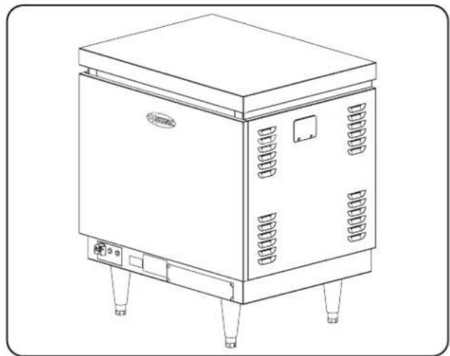
natural_image
Line drawing of a laboratory equipment cabinet with control panel and mounting feet (no text or symbols)PMG-100
Model PMG-200
Model PMG-200 features six tube-type burners, a Power I/O (on/off) switch, indicator lights, and 6" (152 mm) legs. PMG-200 units provide up to 452 gallons per hour (GPH) (1711 liters per hour [LPH]) of sanitizing rinse water based on a 40°F (22°C) temperature rise.
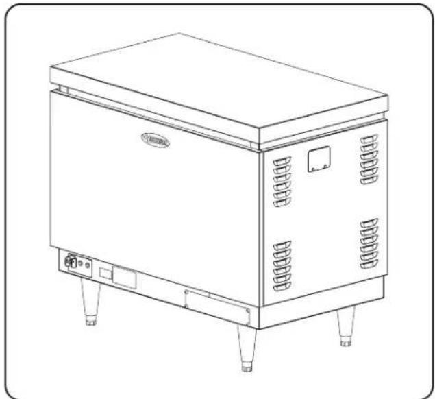
natural_image
Line drawing of a stainless steel industrial machine with control panel and mounting feet (no text or symbols)PMG-200
NOTE: Hatco Booster Water Heaters are approved for use with commercial dishmachines only.
NOTE: Refer to the OPTIONS AND ACCESSORIES section for information on available options.
Hatco® Powermite Gas Booster Water Heaters are designed to maintain a water temperature of 180°F (82°C) required for the sanitizing rinse cycle of commercial dishmachines. An inlet water temperature of at least 43°C (110°F) will produce optimum results (See Water Temperature Recovery Table in the SPECIFICATIONS section).
After the necessary power, water, and gas connections are completed, start the unit by turning on the Power I/O (on/off) switch located on the lower front base. The water circulating pump will start at this time. Providing that operating and safety controls are satisfied, the ignition module will begin a 20 second safety pre-purge. Next, it will energize the spark igniter and turn on the gas for the pilot. The igniter will spark for about 90 seconds or until proof of a pilot fire. If there is a confirmed pilot fire and the water temperature is below the setpoint, the unit will go into full burn. The unit will stay in full burn until the desired setpoint temperature is met, then the burner will shut off. During standby periods of limited use, the burner will cycle on only to replace standby water temperature loss. If for some reason the unit did not ignite, there is an automatic five minute delay before the unit attempts to ignite again.
During operation, water enters the Booster Water Heater at the inlet water connection and flows into the stainless steel tank. It then is pumped through the finned tube heat exchanger where it is heated to the proper temperature. The heated water then returns back to the top half of the stainless steel tank for supply to the dishmachine. Water that is not used immediately by the dishmachine is recirculated through the heat exchanger by the water circulating pump.
If the unit overheats above the setpoint temperature, the safety high limit will open, shutting down the burner, locking out the controller, and turning on the alarm pilot light. In order to reset the unit, turn the unit off and depress the reset button on the appropriate high limit switch, the tank high limit is located behind front panel on the left hand side of the vertical control panel. The heat exchanger high limit is located on the front of the heat exchanger. The switches will not reset until the temperature has dropped to a safe level. This unit must remain off for at least 10 seconds before it can be restarted.
NOTA: The temperature control is factory preset at 88^ C ( 190^ F).
NOTA: The water circulating pump will stay on as long as the Power I/O (on/off) switch is in the I (on) position.
SPECIFICATIONS
General
| Type Gas-fired, instantaneous | recirculating booster water heater with accumulator for use with door-type dishmachines. Unit is floor mounted. |
| Capacity PMG-100: Input 105 | 5,000 BTUs/Hour. Output 84,800 BTUs/Hour = 24.8 kW |
| PMG-200: Input 195,000 BTUs/Hour. Output 156,000 BTUs/Hour = 45.7 kW | |
| Fuel Natural Gas @ 5 inches | water column (wc) — minimum inlet gas pressure |
| Propane @ 11 wc — minimum inlet gas pressure | |
| Operating Water Pressure | 150 pounds per square inch (psi) maximum (relief valve set at 150 psi), 210°F (99°C). |
| Power Supply 120 VAC, 15 a | mp service (unit uses 3.0 amps @ 120 volts). |
| Ignition Electronic spark pilot | with flame proofing by rectification. |
| Temperature Control | Electronic, temperature control probe/microprocessor based. Factory preset at 190°F (88°C). |
| Safety Systems | Energy cut off devices include manual reset heat exchanger high limit and manually reset tank high limit. Redundant gas solenoid valve with integral regulator. Temperature/Pressure relief valve on tank. |
| Fluing | Direct — combustion air enters bottom, flue gases exit right side or back at top of unit |
| Vent Forced draft system with | 4" (102 mm) diameter vent pipe adapter (straight or 90°) |
| Water Circulating Pump Rec | circulating with bronze housing. |
| Connections Gas: 3/4" NPT | |
| Water: 3/4" NPT | |
| Electric: 120 VAC, 15 Amp | |
| Shipping Weight PMG-100: | 180 pounds (82 kg) dry |
| PMG-200: 215 pounds (98 kg) dry |
Water Temperature Recovery Table—Fahrenheit
| Model | Input MBH(1000 /Hour) | Gallons Per Hour (GPH) at Indicated Temperature Rise (°F) | ||||
| 30° 40° 50° | 60° 70° | |||||
| PMG-100 105 3 | 21 241 193 161 138 | |||||
| PMG-200 195 6 | 02 452 361 301 258 | |||||
NOTE: Capacity is reduced at altitudes above 2000 feet (610 m). See "High Altitude Installation and Operation" in the INSTALLATION section for sizing considerations.
Dimensions
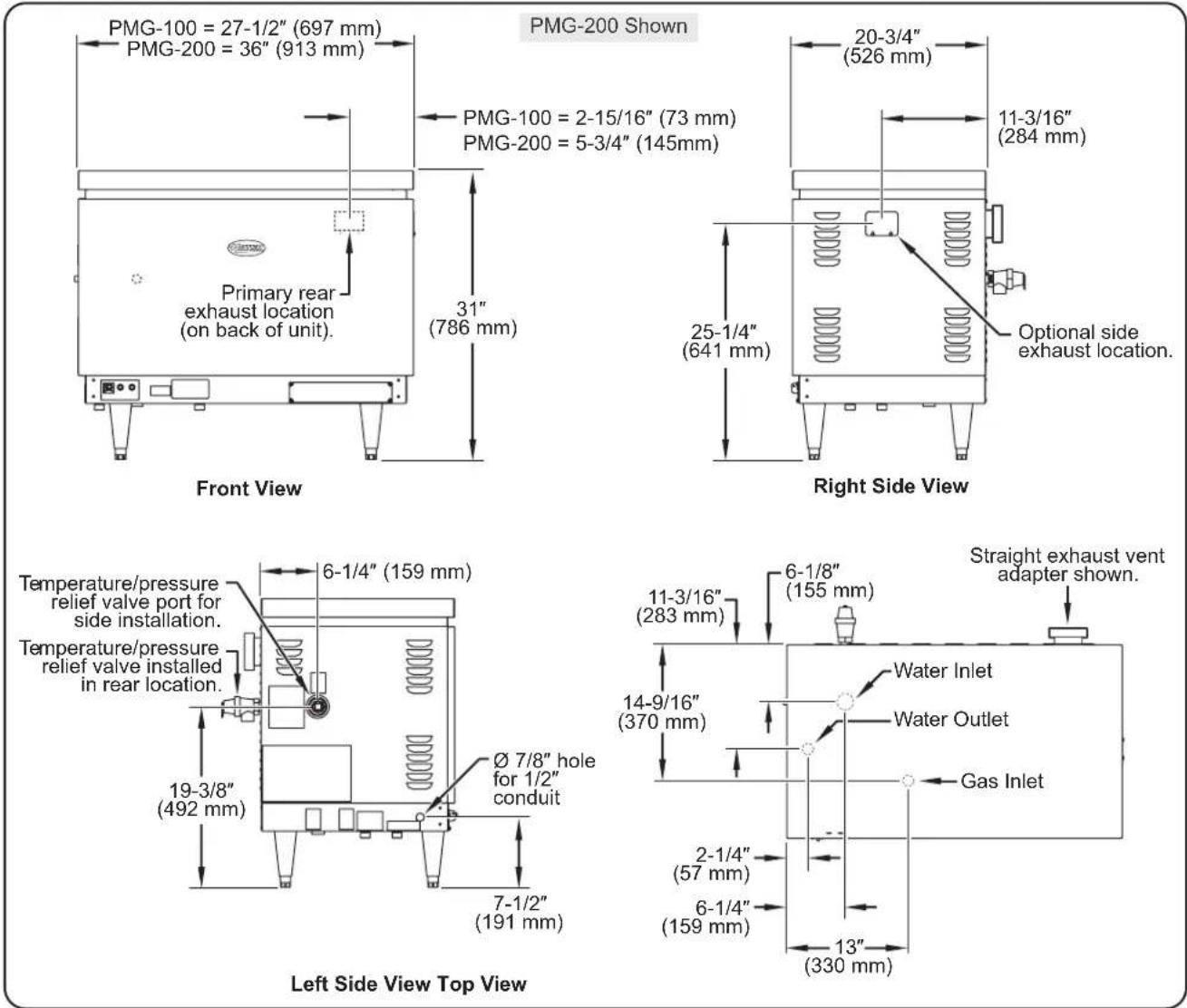
General
WARNING
FIRE OR EXPLOSION HAZARD:
- Unit must be installed by qualified, trained installers. Installation must conform to all local plumbing and gasfitting codes. Installation by unqualified personnel will void the unit warranty and may lead to fire or explosion causing property damage, personal injury, or death. Check with local plumbing inspectors for proper procedures and codes.
- The gas used with this unit must be the type specified on the spec plate on this unit. To avoid personal injury or damage to the unit, never use any other than the specified gas.
- The heater and its gas connection must be leak tested before placing the Booster Water Heater in operation. Use soapy water or commercially available fluid for leak test. DO NOT use open flame to test for leaks.
- If the information in these instructions is not followed exactly, fire or explosion may result causing property damage, personal injury, or death
ELECTRIC SHOCK HAZARD:
- Unit must be installed by qualified, trained installers. Installation must conform to all local electrical codes. Installation by unqualified personnel will void the unit warranty and may lead to electric shock or burn, as well as damage to unit and/or its surroundings. Check with local electrical inspectors for proper procedures and codes.
- Unit is not weatherproof. Locate unit indoors where ambient air temperature is a minimum of 70^ (21°C).
- If an external electrical source is utilized, the appliance, when installed, must be electrically grounded in accordance with local codes, or, in the absence of local codes, with the National Electrical Code, ANSI/NFPA 70, and CSA C22.1, Electrical Code.
To assure proper operation and avoid a possible unsafe condition, the Booster Water Heater must be installed in a horizontal position with the base parallel to the floor and the inlet connection at the lowest point.
Install Booster Water Heater in a horizontal position with the base parallel to the floor and the inlet connection at the lowest point. Improper installation could create an unsafe condition.
Install booster water heater as close as possible to a commercial dish machine. Employ re-circulation if distance between water heater and dish machine exceeds NSF specifications of five (5) linear feet (1524 mm).
CAUTION
BURN HAZARD: Valves supplied by Hatco® are designed for high temperature commercial operation. Do not substitute Hatco valves with valves designed for domestic water heaters.
CAUTION
Incoming water temperature should be minimum of 85^ F ( 29^ C). Damage to the heater can occur if water is cooler than 85^ F ( 29^ C).
Unit is not weatherproof. Unit must be located indoors where ambient air temperature is constant and is a minimum of 70^ F ( 21^ C).
NOTICE
If water supply pressure to the booster inlet is over 20 psi (138 kPa) during flow, install pressure reducing valve with built-in bypass (Hatco P/N 03.02.004.00) for proper operation of dish machine rinse nozzles.
NOTE: The pressure reducing valve must be the type equipped with a high pressure bypass, as supplied by Hatco.
Code Requirements
Installation must be in accordance with local codes, or in the absence of local codes, with the latest edition of the National Fuel Gas Code, ANSI Z223.1, the National Electrical Code, ANSI/NFPA 70. Canadian installations should conform with CSA-B149.1, Natural Gas and Propane Installation Code, and CSA-C22.1 Electrical Code, and/or local installation codes.
NOTE: In the Commonwealth of Massachusetts, Hatco Booster Water Heaters shall be installed by a licensed plumber and gasfitter.
NOTE: The Commonwealth of Massachusetts requires that if a water treatment system is installed in line with the Hatco Booster Water Heaters, a water backflow protector shall also be installed.
NOTE: If a check valve or water backflow protector is installed and cannot be removed, install a back pressure relief valve (Hatco P/N 03.02.039.00) set at 125 psi (862 kPa) on the incoming line between the pressure reducing valve and the inlet to the Booster Water Heater. Discharge must be to open site drain.
For the most effective operation, install the Hatco Gas Booster Water Heater as close as possible to the dishmachine.
NOTE: Employ external recirculation if distance between booster and dishmachine exceeds the NSF specification of 5' (1.5 m).
The Booster Water Heater must not be installed directly on carpeting, but on top of a metal, wood (or equivalent) panel extending beyond the full width and depth of the heater by at least 3" (76 mm) in any direction or, if the heater is installed in an alcove, the entire floor must be covered by the panel. The panel must be strong enough to carry the weight of the Booster Water Heater when full of water.
Adequate front clearance is required to allow for accessibility to the control compartment.
The Booster Water Heater should be located in an area where leakage of the tank or connections will not result in damage to the area adjacent to the heater or to lower floors of the structure. When such locations cannot be avoided, it is recommended that a suitable drain pan, adequately drained, be installed under the Booster Water Heater. The pan must not restrict combustion air flow.
Combustion/Ventilation Air
WARNING
The flow of air to the heater for combustion and ventilation MUST NOT be obstructed. Air vents on the bottom and side of the unit should never be blocked. All panels should be in place during normal operation for optimal performance and safety.
This unit is designed to vent to the outside or into an open Equipment Hood, and is intended for commercial food service water heating only. NOT FOR RESIDENTIAL USE. See “Venting Installation” in the INSTALLATION section of this manual.
Flue gases exit top side or back of this unit and must not be obstructed, specified clearances must be maintained for safe operation. See "Venting Installation" in the INSTALLATION section for vent piping alternatives.
CAUTION
The use of cellular core PVC (ASTM F891), cellular core CPVC, or Radel® (polyphenylsulfone) in nonmetallic venting systems is prohibited. Covering non-metallic vent pipe and fittings with thermal insulation is also prohibited.
The Booster Water Heater must be located in an area that allows for an adequate supply of air for proper combustion and ventilation in accordance with Section 5.3 and 7.2.2 of the National Fuel Gas Code NFPA54/ANSI Z223.1 or applicable provisions of the local building codes. Only a single booster appliance may be installed in this manner. Installations under the jurisdiction of Canadian CSA-B149.1, Natural Gas and Propane Installation Code, require a gas interlock tied into the ventilation hood system.
High Altitude Installation and Operation
Atmospheric conditions at elevations above 2000 ft. (610 m) have an effect on the performance of most gas fired products. For this reason, historical models for altitude de-rating were developed for gas appliances with atmospheric burners. The National Fuel Gas Code, ANSI Z223.1, is an accepted model that requires a de-rating of 4% per 1000 ft. (305 m) elevation when no testing to the contrary exists for that product. This could require modifying the equipment and adjusting settings in the field to achieve de-rating. Testing has shown this to be a very conservative approach.
Manufacturers discourage unnecessary field adjustments in order to maintain a level of performance and quality designed into the product. For these and other reasons, testing was underwritten through CSA International to verify an improved satisfactory performance with little or no modification to effect input rate or control. The following text and charts are a result of this testing and should be used during application sizing and installation.
- The PMG-100 can operate at better levels than ANSI Z223.1 without manifold pressure setting adjustments or orifice changes up to the 8500 ft. (2593 m) elevation for both natural gas and liquid propane gas units. Above this level only a slight decrease in manifold pressure may be needed to meet the approved BTU rate. This is shown in the Altitude Summary chart. Also, note that GPH capacity will be reduced and a guideline is given as to the percent of sea level capacity expected.
For Canadian installations between 2000-4500 feet (610-1370 m) de-rate unit by 10% to 94,500 BTU.
- The PMG-200 will require orifice changes at levels shown in the Altitude Summary chart. This follows the 4% derating scheme outlined in ANSI Z223.1 for both natural gas and liquid propane gas. Also note that the GPH capacity will be reduced and a guideline is given as to the percent of sea level capacity expected.
For Canadian installations between 2000-4500 feet (610-1370 m) de-rate unit by 10% to 175,500 BTU.
Orifice Kits for altitude installations may be ordered through Hatco Customer Service. Please call for orifice sizing information.
Minimum Clearance Requirements
| Floor* Top Left Side Right Side Front | Back | † | |||
| 6"(152 mm) | 1"(25 mm) | 2"(51 mm) | 2"(51 mm) | 20"(508 mm) | 2"(51 mm) |
* Includes legs supplied with Booster Water Heater.
† Minimum clearance of 8" (203 mm) from the side of the appliance where the vent is installed.
Altitude Summary Publication Data for PMG Booster Water Heaters
Natural Gas
| AltitudeFeetMeters | 0–2000(0–610) | 2001–3000(610–915) | 3001–4000(915–1220) | 4001–5000(1220–1525) | 5001–6000(1525–1830) | 6001–7000(1830–2135) | 7001–8000(2135–2440) | 8001–8500(2440–2593) | 8501–9500(2593–2898) | 9501–10500(2898–3203) |
| PMG-100Approved Input Rate * | 105000 | 103363 | 101726 | 100089 | 98452 | 96815 | 95178 | 94360 | 90585 | 86811 |
| Suggested Orifice Size † | #34DMS | #34DMS | #34DMS | #34DMS | #34DMS | #34DMS | #34DMS | #34DMS | #34DMS | #34DMS |
| GPH Capacity De-Rate • | 1 0.98 | 0.97 0.95 | 0.94 0.92 | 0.91 0.90 0.86 | 0.83 | |||||
| PMG-200Approved Input Rate * | 195000 | 171600 | 163800 | 156000 | 148200 | 140400 | 132600 | 128700 | 123552 | 118404 |
| Suggested Orifice Size † | #35DMS | #36DMS | #36DMS | #37DMS | #37DMS | #38DMS | #39DMS | #40DMS | #41DMS | #42DMS |
| GPH Capacity De-Rate • | 1 0.88 | 0.84 0.80 | 0.76 0.72 | 0.86 0.66 0.63 | 0.61 |
Liquid Propane Gas
| Altitude Feet Meters | 0–2000 (0–610) | 2001–3000 (610–915) | 3001–4000 (915–1220) | 4001–5000 (1220–1525) | 5001–6000 (1525–1830) | 6001–7000 (1830–2135) | 7001–8000 (2135–2440) | 8001–8500 (2440–2593) | 8501–9500 (2593–2898) | 9501–10500 (2898–3203) |
| PMG-100 LPG Approved Input Rate * | 105000 | 102937 100 | 874 98810 | 96747 946 | 84 92621 9 | 1589 87925 | 84262 | |||
| Suggested Orifice Size † | #50DMS | #50DMS | #50DMS | #50DMS | #50DMS | #50DMS | #50DMS | #50DMS | #50DMS | #50DMS |
| GPH Capacity De-Rate • | 1 0.98 | 0.96 0.94 | 0.92 0.90 | 0.88 0.87 0 | 84 0.80 | |||||
| PMG-200 LPG Approved Input Rate * | 195000 | 171600 | 163800 | 156000 | 148200 | 140400 | 132600 | 128700 | 123552 | 118404 |
| Suggested Orifice Size † | #50DMS | #51DMS | #51DMS | #51DMS | #51DMS | #52DMS | #52DMS | #52DMS | #53DMS | #53DMS |
| GPH Capacity De-Rate • | 1 0.88 | 0.84 0.80 | 0.76 0.72 | 0.86 0.66 0 | 63 0.61 |
* This is the maximum allowable BTU rate certified by CSA. These are to be verified by the qualified gas installer on site. Check Heat Value with local Gas Utility.
† The first orifice size is the factory built unit. The next sizes are shown at the altitudes where a change is required to allow pressure adjustments to the approved input rates.
- This is a de-rate multiplier to use when sizing a Hatco® Gas Booster Water Heater for a given application. Multiply this number by the GPH rating of the desired Booster Water Heater to ensure it will provide the required GPH capacity. This number also can be divided into the required GPH capacity to find the adjusted GPH that corresponds with the GPH ratings of Hatco Gas Booster Water Heaters.
Plumbing Installation
Components
| Supplied With Unit Optional | With Unit Supplied By Installer | |
| Temperature/Pressure Relief Valve Back Pressure Relief Valve 3/4" Gate or Ball Valve | ||
| Blended Phosphate Water Treatment System | Piping Unions | Drain Valve |
| Pressure Reducing Valve 3/4" Plug | ||
| Temperature/Pressure Gauge (2) 3/4" | ||
| Shock Absorber | ||
| 3/4" Plug (installed) | ||
WARNING
Do not connect booster water heaters to domestic (consumer) dish machines or other domestic utilized equipment. This booster may damage domestic equipment.
Do not connect an expansion tank of any type to Booster Water Heater water lines.
Use only copper plumbing material. Non-copper plumbing material may create an unsafe condition.
CAUTION
Do not connect Booster Water Heater directly to a boiler or furnace coil or any other uncontrolled temperature source. The Booster Water Heater thermostat could be damaged causing unit to overheat.
NOTE: If a check valve or water backflow protector is installed and cannot be removed install a back pressure relief valve, Hatco P/N 03.02.039.00, set at 125 psi (862 kPa) on the incoming line between the pressure reducing valve and the inlet to the Booster Water Heater. Discharge must be to open site drain.
Pressure And Temperature Relief Valves
For protection against excessive pressures and temperatures in the Booster Water Heater, install temperature and pressure protective equipment by local codes. Hatco supplies valves constructed with brass working parts and heat resistant silicone seat discs for all Booster Water Heater models.
WARNING
Temperature/pressure protective equipment should not be less than a combination temperature/pressure relief valve certified by a nationally recognized testing laboratory that maintains periodic inspection of the production of this equipment and meets the requirements for Relief Valves and Automatic Shutoff Devices for Hot Water Supply Systems, CSA AN SI Z21.22 /CSA 4.4. The temperature/ pressure relief valve must be marked with a minimum set pressure not to exceed the marked hydrostatic test pressure of the Booster Water Heater as noted on the unit specifications.
WARNING
FOR INSTALLING PRESSURE AND TEMPERATURE RELIEF VALVES IN ACCORDANCE WITH CSA ANSI Z21.22/CSA 4.4. Combination pressure and temperature relief valves with extension thermostats must be installed so that the temperature-sensing element is immersed in the water within the top 6" (152 mm) of the tank. They must be installed directly in a tank tapping. Combination pressure and temperature relief valves that do not have extension elements must be mounted directly in a tank tapping located within the top 6" (152 mm) of the tank, and shall be adequately insulated and located so as to assure isolation from ambient conditions that are not indicative of stored water temperature. TO AVOID WATER DAMAGE OR SCALDING DUE TO VALVE OPERATION, DRAIN PIPE MUST BE CONNECTED TO VALVE OUTLET AND RUN TO A SAFE PLACE OF DISPOSAL. Discharge line must be as short as possible and be the same size as the valve discharge connection throughout its entire length. Drain line must pitch downward from the valve and must terminate between 1-1/2" (38 mm) and 6" (152 mm) above the floor drain where any discharge will be clearly visible. The drain line shall terminate plain, not threaded, with material serviceable for temperatures up to 250°F (121°C) or greater. Excessive length, over 30' (9.1 m), or use of more than four elbows can cause a restriction and reduce the discharge capacity of the valve. No shut-off valve shall be installed between the relief valve and tank, or in the drain line. Valve lever must be tripped periodically to assure that waterways are clear. This device is designated for emergency safety relief and shall not be used as an operating control. The valves are set to relieve at 150 psi (1034 kPa) or when water temperature reaches 210°F (99°C). Read tag on valve for additional information.
CAUTION
BURN HAZARD: Valves supplied by Hatco are designed for high temperature commercial operation. Do not substitute Hatco valves with valves designed for domestic water heaters.
Do not use an anti-siphon or check valves on incoming water line. Damages caused by the use of these valves on unit will not be covered by warranty.
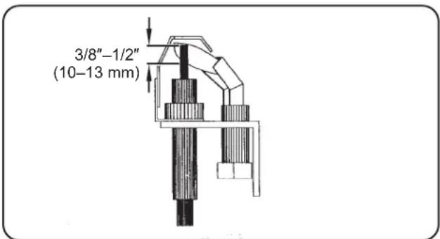
Temperature/Pressure Gauges
Hatco ^® requires a temperature/pressure gauge be installed in both the inlet and outlet lines to the Booster Water Heater. These gauges provide an instant visual check of the water temperature and pressure entering and leaving the Booster Water Heater. The visual check is helpful in eliminating unnecessary service calls.
Install the temperature sensing bulb in the water system. See the illustrations below for methods of installation.
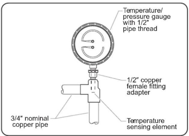
Recommended Temperature/Pressure Gauge Installation
Alternate Temperature/Pressure Gauge Installation
CAUTION
Hatco requires that two temperature/pressure gauges (Hatco P/N 03.01.003.00) be installed to ensure proper operation. Install one in the supply line before the pressure reducing valve and one in the outlet line as close to the Booster Water Heater as possible. This provides a visual check of the water temperature and pressure before and after the water heater.
Pressure Reducing Valve
Proper operation of most dishmachine rinse nozzles require available water flow pressure at the nozzle to be 20 psi.
If water pressure available to the Booster Water Heater inlet is over 20 psi, a pressure reducing valve with bypass must be installed in the hot water supply line to the Booster Water Heater.
The valve supplied by Hatco has a built-in high pressure bypass which prevents excessive pressure build-up as the booster heats up. CAUTION! Pressure regulating valve must have a built-in high pressure bypass.
Blended Phosphate Water Treatment System
Hatco requires that the Blended Phosphate Water Treatment System supplied be installed with unions on the incoming 3/4" water supply line after the pressure reducing valve and before the Booster Water Heater.
Cartridges supplied have a usage rating of 100,000 gallons of water. To ensure proper operation the cartridges must be replaced when expired.
NOTE: Product failure caused by liming or sediment buildup is not covered under warranty.
NOTE: The Commonwealth of Massachusetts requires that if a water treatment system is installed in line with the Hatco Booster Water Heaters, a water backflow protector shall also be installed.
NOTE: If a check valve or water backflow protector is installed and cannot be removed, install a back pressure relief valve (Hatco P/N 03.02.039.00) set at 125 psi (862 kPa) on the incoming line between the pressure reducing valve and the inlet to the Booster Water Heater. Discharge must be to open site drain.
Plumbing Connections
NOTICE
Incoming water supply to Booster Water Heater must be a minimum of 20 psi (1.4 kg/cm2). Water pressure less than 20 psi (1.4 kg/cm2) will decrease operating life of recirculating pump and unit.
NOTE: Product failure caused by incoming water pressure less than 20 psi (1.4 kg/cm2) is not covered under warranty
Do not back out or loosen any pipe fittings or leaks may occur.
Incoming water in excess of 3 grains of hardness per gallon (GPG) (0.75 grains of hardness per liter [GPL]) must be treated and softened before being supplied to Booster Water Heater(s). Water containing over 3 GPG (0.75 GPL) will decrease efficiency, increase energy use, and reduce the operating life of the unit through increased lime build-up. Product failure caused by liming or sediment buildup is not covered under warranty.
Inlet
Hatco Booster Water Heaters are designed to be connected with 3/4" pipe at the inlet pipe from the primary water heater. Water temperature from the primary water heater must be at least 110°F (43°C) and should not exceed 160°F (71°C). Minimum temperature differential between the inlet and outlet temperature must never be less than 20°F (11°C).
Inlet line must be installed with a shut-off valve, a full open gate or ball type valve, a 3/4" union, together with the blended phosphate water treatment system, pressure reducing valve set at 20 psi (1.4 kg/cm2) flow pressure and a temperature/pressure gauge supplied by Hatco.
NOTE: Do not run a cold ground water line to the Booster Water Heater.
NOTE: Be sure water flows through the pressure reducing valve in the proper direction. Check the directional arrow. Valve will reduce pressure only during flow conditions.
A 3/4" union fitting and a drain valve also must be installed to allow for easy servicing.
The temperature/pressure relief valve must be installed into one of two locations on the heater: either the right side or the back of the unit. See the "Plumbing Connections" illustrations in this section for exact locations.
To prevent water leakage and damage to the unit, the location for the temperature/pressure relief valve that is not used must be plugged. (One plug is supplied by Hatco with the heater.) Both temperature/pressure fittings must not be plugged.
NOTE: The Commonwealth of Massachusetts requires that if a water treatment system is installed in line with the Hatco Booster Water Heaters, a water backflow protector shall also be installed.
Outlet
Using a 3/4" union and piping, connect the Booster Water Heater water outlet to the dishmachine sanitizing rinse pipe connection.
NOTE: Be certain the connection is made to the final rinse and not to the wash tank.
Install a temperature/pressure gauge in outlet line. Water temperature at outlet should be 180^ F ( 82^ C).
NOTE: The temperature sensing element must be in water stream.
Shock Absorber
In areas of high water pressure, Hatco recommends a shock absorber be installed in the outlet line as close as possible to the dishmachine. The shock absorber softens the water hammer caused by automatic dishmachine valves.
NOTE: Fill Booster Water Heater with water to test for installation leaks. Leave the water in booster to prevent pump damage in the event the electrician should apply power.
Plumbing Connections—PMG-100/200 Gas Booster Water Heaters
Plumbing Connections—PMG-100/200 Gas Booster Water Heaters Connected in Series
flowchart
graph TD
    A["Back Pressure Relief Valve"] --> B["Regulator with High Pressure By-pass set at 20 psi."]
    B --> C["Inlet"]
    C --> D["3/4" Gate or Ball Valve*"]
    D --> E["Temperature/Pressure Gauge"]
    E --> F["Blended Phosphate Water Treatment System"]
    F --> G["Drain Valve*"]
    G --> H["Floor Drain"]
    H --> I["Maximum inlet water temperature not to exceed 160°F (71°C)."]
    I --> J["Drain Valve*"]
    J --> K["Floor Drain"]
    K --> L["Drain Valve*"]
    L --> M["Outlet"]
    M --> N["Outlet"]
    N --> O["Outlet"]
    O --> P["Shock Absorber for water hammer."]
    P --> Q["180°F (82°F) hot rinse water to dishmachine."]
    Q --> R["Discharge from T/P Relief Valve. Air gap must comply with plumbing code."]
    R --> S["Temperature/Pressure Gauge"]
    S --> T["Temperature/Pressure Relief Valve, 150 PSI/210°F (1034 kPa/99°C)"]
* Not Supplied With Booster Water Heater.
- Optional Accessory
Gas Installation
Components
| Supplied With Unit Optional | With Unit Supplied By Installer | |
| Internal Gas Valve (installed) None | Gas Supply Line | |
| External Gas Shut-Off Valve (loose) Sediment Trap | ||
| Union | ||
| Vent System | ||
WARNING
FIRE OR EXPLOSION HAZARD:
- The gas used with this unit must be the type specified on the spec plate on this unit. To avoid personal injury or damage to the unit, never use any other than the specified gas.
- The heater and its gas connection must be leak tested before placing the Booster Water Heater in operation. Use soapy water or commercially available fluid for leak test. DO NOT use open flame to test for leaks.
- The Booster Water Heater and its individual shut-off valve must be disconnected and isolated from the gas supply piping system during any pressure testing of the system at test pressures in excess of 1/2 psi (3.5 kPa.).
- This appliance must be isolated from the gas supply piping system by closing its individual manual shutoff valve during any pressure testing of the gas supply piping system at test pressures equal to or less than 1/2 psig (3.5 kPa).
- Dissipate test pressure from the gas supply line before re-connecting the heater and its manual shut-off cock to the gas supply line. Failure to follow this procedure may damage the gas valve. Over-pressurized gas valves are not covered by the warranty.
- If the information in these instructions is not followed exactly, fire or explosion may result causing property damage, personal injury, or death.
Gas Piping
CAUTION
DO NOT use Teflon tape on gas line pipe threads. A flexible sealant suitable for use with applied gas is recommended.
The gas inlet pipe size is 3/4" NPT pipe thread fitting to the gas valve. Provide an adequate size gas supply line. The line should never be smaller than 3/4" NPT and should follow according to the gas piping diagram below. The fitting is accessed through the bottom of the case.
NOTE: Gas line should be of the approved type for use with natural gas or propane.
Gas line should be kept as short as possible, sized to furnish the rated BTU, and installed in a way to protect it from damage. Gas piping must be installed in accordance with local plumbing codes including a sediment trap, ahead of the heater gas controls and a manual shut-off valve located outside the jacket.
NOTE: The internal gas valve is supplied with the heater, the external manual gas valve supplied with unit must be plumbed in by the installer.
Incoming Gas Pressure Specifications
| Gas Type | Inches Water Column | |
| Minimum | Maximum | |
| Natural Gas | 5.0 | 10.5 |
| Propane/LP Gas | 11.0 | 13.0 |
The maximum inlet gas pressure must not exceed the values shown above. The minimum gas pressure listed is for the purposes of input adjustment.
The manifold inside the heater is provided with a pressure tap to measure the gas pressure. The chart below lists the proper pressure amounts at the manifold pressure tap when testing.
Operating Pressure Specifications at Manifold
| Gas Type | Inches Water Column at Pressure Tap |
| High Burn | |
| Natural Gas | 3.5 |
| Propane/LP Gas | 10.0 |
See the "Gas Installation Diagram" illustration for hook-up location and pressure tap location.
Gas Installation Diagram
Electrical Installation
Components
| Supplied With Unit Optional With Unit Supplied By Installer | |
| 7/8" Hole Plugs None 120 VAC, 60 Hz, 15 A, | Single Phase Service |
| Electrical Ground |
WARNING
ELECTRIC SHOCK HAZARD:
- Unit must be installed by qualified, trained installers. Installation must conform to all local electrical codes. Installation by unqualified personnel will void the unit warranty and may lead to electric shock or burn, as well as damage to unit and/or its surroundings. Check with local electrical inspectors for proper procedures and codes.
- If an external electrical source is utilized, the appliance, when installed, must be electrically grounded in accordance with local codes, or, in the absence of local codes, with the National Electrical Code, ANSI/NFPA 70, and CSA C22.1, Electrical Code.
CAUTION
DO NOT turn on power to the Booster Water Heater until tank has been filled with water and all air has been vented through the dish machine rinse nozzles. Heating elements will burn out in seconds if operated when not immersed in water.
The Hatco ^® Gas Booster Water Heater operates on 120 VAC, 60 Hz, 15 amp, single phase service. All internal electrical connections have been made at the factory.
Electrical Connections
To connect the field wiring to the Booster Water Heater:
- Remove the front access panel from the unit by lifting up on the front panel and pulling upper edge away from unit until it clears the lower edge.
- Open electrical enclosure at the lower left corner of the base by removing two screws.
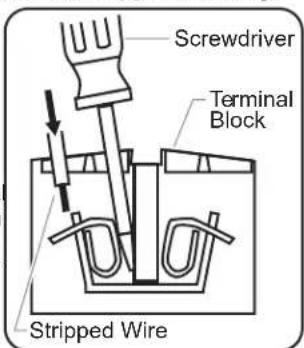
- Bring power leads from a properly sized fused disconnect switch or circuit breaker through 7/8" hole provided on lower left hand side or bottom of base. Connect supply lines to terminal block provided. Use copper wire only.
a. Rotate screwdriver into top opening.
b. Insert 3/8" stripped wire lead.
c. Remove screwdriver.
- A green grounding terminal is provided internally. An equipment grounding conductor must be properly connected to the green terminal block.
Venting Installation
The PMG-100 and PMG-200 may be vented by two methods, both of which have been tested for compliance with national safety standards for gas water heaters. Whichever method is used must comply with local codes. The installation of the venting system must comply with local codes and in the absence of local codes, in accordance with the National Fuel Gas Code and the guidelines in this manual. Before installing any method of venting, contact the local code authority of your gas supplier to make sure that the final installation will be acceptable to the authorities having jurisdiction.
The proper method of venting a power vented gas appliance is too complicated to cover in this manual and is explained in detail in the National Fuel Gas Code. Before installing the venting system, the person or agency making the installation must be familiar and experienced with the guidelines of the National Fuel Gas Code.
The temperature of the flue gases from this booster water heater operates at approximately 225^ F to 275^ F ( 107^ C to 135^ C).
The two methods that have been tested for compliance with the national safety standards are:
- The first method of venting permits the connection of 4" (102 mm) diameter, AL 29-4C1 stainless steel vent pipe. Use only Duravent "FasNSeal" products currently listed to ANSI/UL 1738 by a nationally recognized testing agency for category III venting. The maximum combined horizontal vent length must not exceed a length of 40 feet (12 m) [each sweep elbow is the equivalent of 5' (1.5 m) of straight pipe and a standard right elbow is the equivalent of 10' (3 m)]. Venting shall be installed per vent pipe manufacturer's instructions. The venting may be done in such a way that the exhaust products are:
a. Conveyed to another area in the kitchen such as under a ventilator or near an exhaust fan (both of which exhaust outdoors).
When using this method the booster water heater must be electrically interlocked with the vent hood to prevent operation if the vent hood is not operating.
The termination end must be placed so that it vents above the bottom of the hood skirt. Do not penetrate the filter with the vent.
b. Horizontally vented through an outside wall directly to the outdoors. See the additional instructions and illustration below.
c. Exhausted into a vertical masonry chimney that has a listed steel liner installed in the chimney. Locate appliance as close as practicable to a chimney or gas vent. Because of the low flue gas temperature, do not vent into an unlined or masonry lined chimney designed to burn solid fuel. Note that all venting into a vertical chimney of any type must comply with the horizontal and vertical ratios and sizing requirements that are detailed in the National Fuel Gas Code.
d. For Model PMG-100 only: Vented vertically using type B vent pipe that is 5" (127 mm) in diameter provided the termination above the roof uses a listed wind cap.
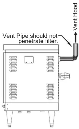
Venting Through Typical Exhaust System
- The second method of venting is to directly exhaust the flue products into the kitchen work area provided the size and installation of the open room meet the requirements of the National Fuel Gas Code [ANSI Z223.1 or NFPA bulletin #54]. A portion of the 1996 code is as follows.
Excerpt From ANSIZ223.1/NFPA #54
7.2.1 Connection To Venting Systems. Excerpt as permitted in 7.2.2 through 7.2.6, all gas utilization equipment shall be connected to venting systems.
7.2.2 Equipment Not Required To Be Vented. A single booster-type [automatic instantaneous] water heater, when designed and used a rinse requirements of a dishmachine, provided that the equipment is installed, with the draft hood in place and unaltered, if a draft hood is required in a commercial kitchen having a mechanical exhaust system. Where installed in this manner, the draft hood shall not be less than 36" (91 cm) vertically and 6" (15 cm) horizontally from any surface other than the equipment.
Where any or all of this equipment is installed so the aggregate input rating exceeds 20 BTU per hr per cu ft (207 watts per m3) of room space in which it is installed, one or more shall be provided with venting systems or other approved means for removing the vent gases to the outside atmosphere so the aggregate input rating of the remaining unvented equipment does not exceed the 20 BTU per hr per cu ft (207 watts per m3) figure. Where the room or space in which the equipment is installed is directly connected to another room or space by a doorway, archway, or other opening of comparable size that cannot be closed, the volume of adjacent room or space shall be permitted to be included in the calculation.
CAUTION
To avoid freezing water damage to the Booster Water Heater when the outside temperature is below 32^ F ( 0^ C), the unit must be left ON and the venting must be protected from migrating cold air.
General Notes On Venting:
- The appliance shall have dedicated venting and not share common or multi-story flue configurations.
- Whenever a vent pipe goes through a combustible wall, the clearance between the vent material and the combustible material must be in accordance with the listing requirements of the vent system chosen. See the vent manufacturer's instructions.
- All horizontal runs of vent pipe must be supported at every elbow and every 3' (1 m) to prevent sagging.
- All horizontals must have an upward pitch of at least 1/4" per foot.
- Right angle adapter is provided to minimize radius of initial bend toward flue piping required for tight quarters.
NOTE: Right angle duct outlet may be installed with duct exiting up, to the left, or to the right. Do NOT install with duct exiting down.
- When venting through a side wall to the outdoors the following must be observed:
- A vent termination [Tee Fitting] must be used that is positioned with the backside of the TEE at least 12" (305 mm) from the exterior wall.
- The vent termination must be away from areas where the general public will walk or vehicle may damage the vent cap.
- The cap must be at least 3' (1 m) above any forced inlet openings [into the building] that are within 10' (3 m) of the cap.
- The cap must be one foot above any windows, doors or other openings into the building.
- The cap must be 4' (1.2 m) horizontally from any doors, windows, etc.
- The cap must be at least 7' (2 m) above any public walkway.
- The bottom of the cap must be at least 1' (0.3 m) above ground and possibly higher if the snow accumulation normally exceeds 1' (0.3 m).
- The cap should be positioned such that any condensate that drips from the cap will not damage plants, shrubs or onto other equipment located on the outside of the restaurant.
- The cap should be positioned so that condensate that drips from the cap will not allow the water to accumulate on walkways or other areas, which may freeze and cause an accident.
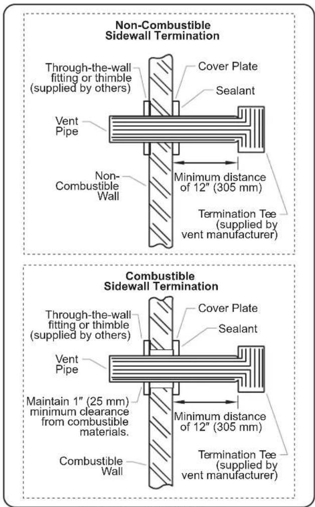
Typical Through-the-Wall Venting
NOTICE
If outside air temperature is 32^ F ( 0^ C) or below, do not turn heater off when not in use. This is to reduce the potential for cold outside air to freeze the water in the heat exchanger.
General
Use the following procedures to operate Hatco ^® Gas Booster Water Heaters.
WARNING
Read all safety messages in the IMPORTANT SAFETY INFORMATION section before operating this equipment.
CAUTION
BURN HAZARD: Water in unit is very hot. Wear protective gloves and proper attire when operating to avoid injury.
Startup
NOTE: Remove the front access panel during start up.
Filling The System With Water
- With the external gas supply and electric supply turned off, close the drain pipe valve.
NOTICE
Incoming water in excess of 3 grains of hardness per gallon (GPG) (0.75 grains of hardness per liter [GPL]) must be treated and softened before being supplied to Booster Water Heater(s). Water containing over 3 GPG (0.75 GPL) will decrease efficiency, increase energy use, and reduce the operating life of the unit through increased lime build-up. Product failure caused by liming or sediment buildup is not covered under warranty.
NOTE: Water temperature at the inlet should be between 110^ F ( 43^ C) and 150^ F ( 66^ C) and should never exceed 160^ F ( 71^ C) for the unit to operate properly and meet the demands of the dishmachine. Minimum temperature differential between inlet and outlet temperatures should never be less than 20^ F ( 11^ C).
NOTE: Do not run a cold ground water line to the Booster Water Heater(s).
- Open the shutoff valve to the primary water supply line.
- When the water tank is full, turn on the electric supply and the power switch to allow the circulator pump to purge air from it. The circulator pump should start immediately. Additional air in the tank can be vented through the dishmachine rinse nozzle.
NOTE: The dishmachine should be cycled a minimum of three times before the gas supply to the booster is turned on.
- After all the air has been vented out of the system, turn off the power to the Booster Water Heater.
NOTICE
Product failure caused by dry firing is not covered under warranty.
Lighting The Heater
WARNING
FIRE OR EXPLOSION HAZARD: If the information in these instructions is not followed exactly, fire or explosion may result causing property damage, personal injury, or death.
FOR YOUR SAFETY, READ BEFORE OPERATING:
- This appliance is equipped with an ignition device which automatically lights the pilot. DO NOT TRY TO LIGHT THE PILOT BY HAND.
- BEFORE OPERATING smell all around the appliance area for gas. Be sure to smell next to the floor because some gas is heavier than air and will settle on the floor.
What To Do If You Smell Gas:
- Do not try to light any appliance.
- Do not touch any electric switch; do not use any phone in your building.
- Immediately call your gas supplier from a neighbor's phone. Follow the gas supplier's instructions.
- If you cannot reach your gas supplier, call the fire department.
-
Use only your hand to push in or turn the gas control knob. Never use tools. If the knob will not push in or turn by hand, don't try to repair it—call a qualified service technician. Force or attempted repair may result in a fire or explosion.
-
Do not use this appliance if any part has been under water. Immediately call a qualified service technician to inspect the appliance and to replace any part of the control system and any gas control which has been under water.
Operating Instructions:
WARNING
Should overheating occur or the gas supply fail to shut off, turn off the manual gas control valve to the appliance.
- STOP! Read the safety information on the appliance label and in this manual.
- Turn off all electric power to the appliance.
- This Booster Water Heater is equipped with an ignition device which automatically lights the pilot. DO NOT try to light the pilot by hand.
- To gain access to controls remove front panel by sliding it up and pulling lower edge out and down away from the appliance.
- Turn gas control knob clockwise to OFF.
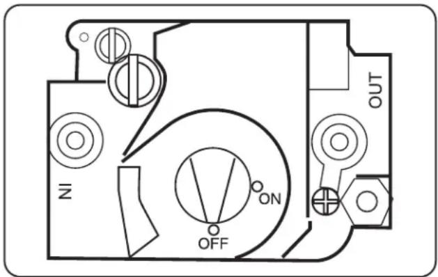
Gas Valve—Top View
- Wait 5 minutes to clear out any gas. If you smell gas. STOP! Follow the "What To Do If You Smell Gas" information above in the "Lighting The Heater" procedure. If you do not smell gas, continue to the next step.
continued...
- Turn gas control knob counterclockwise to ON.
- Replace front access panel.
- Turn on all electric power to the appliance.
- Turn on power switch and:
a. After approximately 20 seconds the ignition sequence should begin and light the pilot. If the water temperature is below the setpoint the heating process will start.
b. Allow the Booster Water Heater to run until the burner shuts down. The Booster Water Heater is now at its setpoint, stabilized working temperature.
c. Run the dishmachine through at least two rinse cycles. After the first rinse cycle, the burner should re-light and remain lit until the water maintains 180^-185^ ( 82^-85^ ) output at 20 psi through the second cycle.
NOTE: If this test does not proceed as described, contact Hatco Corporation or an authorized service agent for technical assistance.
- If the appliance will not operate, follow the "To Turn Off Gas To Appliance" procedure in this section and call a service technician or gas supplier.
To Turn Off Gas To Appliance:
- Turn off power switch on heater.
- Turn off all electric power to the appliance if service is to be performed.
- Shut off external manual gas valve.
- Remove front cover of heater for access to the control compartment.
- Turn gas control knob clockwise to OFF. Do not force.
- Replace front access panel.

To avoid freezing water damage to the Booster Water Heater when the outside temperature is below 32^ F ( 0^ C), the unit must be left on and the venting must be protected from migrating cold air.
MAINTENANCE
General
Gas Booster Water Heaters are designed for maximum durability and performance with minimum maintenance.

ELECTRIC SHOCK HAZARD: Use only Genuine Hatco® Replacement Parts when service is required. Failure to use Genuine Hatco Replacement Parts will void all warranties and may subject operators of the equipment to hazardous electrical voltage, resulting in electrical shock or burn. Genuine Hatco Replacement Parts are specified to operate safely in the environments in which they are used. Some aftermarket or generic replacement parts do not have the characteristics that will allow them to operate safely in Hatco equipment.
This unit must be serviced by qualified personnel only. Service by unqualified personnel may lead to fire, explosion, electric shock, or burn.
ALWAYS turn OFF power at fused disconnect switch/circuit breaker, shut off gas supply, and allow unit to cool before performing any cleaning, adjustments, or maintenance.
This unit has no "user-serviceable" parts. If service is required on this unit, contact an Authorized Hatco Service Agent or contact the Hatco Service Department at 414-671-6350.

Using or storing chlorine based products on or near the Booster Water Heater may shorten the life of the unit and void the product warranty.
NOTE: Refer to the REPLACEMENT PARTS LIST for exploded views, part identification and location.
NOTE: Refer to the WIRING DIAGRAM for specific electrical information.
- Keep the area around the heater free and clear of debris and flammable materials. Do not block air intakes or vents.
- The recirculating water pump motor is permanently lubricated and requires no other maintenance.
- Visually observe and inspect the burner and pilot flame every six months. When the burner is operating properly, a clean blue flame will be visible. Depending on the condition of the kitchen environment, the burner may need to be cleaned of lint or grease-laden dust. If any problems are apparent, discontinue use of the heater and contact the Hatco Corporation or your authorized service agent.
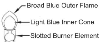
- The flame during full burn is a broad blue color. An inner cone slightly lighter in color will also be visible.
- The flame should not be rising off of the face of the burner element.
- Yellow tipped flames suggest a need for adjustment or cleaning of the burner assembly.
Gas Flame
-
Visually observe and inspect the heat exchanger and exhaust blower fan. Depending on the condition of the kitchen environment, the heat exchanger and fan may need to be cleaned of lint or grease laden dust. If any problems are apparent, discontinue use of the heater and contact the Hatco Corporation or your authorized service agent.
-
Once a month, check and clean (if necessary) all air inlet holes on the side or back of the unit.
-
The front access panel should be removed and all components visually inspected at least twice a year. Check for evidence of chafing or heat damage to any wiring or components. Check also for any signs of water leakage at any of the plumbing connections. If there are signs of any damage or leakage contact the Hatco Corporation or your authorized service agent.
- The relief valve should be manually operated at least once a year to ensure proper operation.
WARNING
Before performing any maintenance/service, care should be taken that any of the discharged water does not come into contact with the operator or surrounding surfaces. Water can be extremely hot and can cause severe scalding and damage to the property.
If relief valve discharges periodically, do not plug valve. If replacing valve does not stop discharge, contact an Authorized Hatco Service Agent or the Hatco Service Department.
- Visually observe and inspect the Blended Phosphate Water Treatment System weekly: To ensure proper operation replace depleted cartridges immediately.
Burner Removal/Inspection
NOTICE
Burner inspection and/or removal must be performed by an authorized service agency.
- Shut-off the electrical power and gas supply to the heater.
- Disconnect the internal flexible gas supply line connector at the gas regulator valve.
- Disconnect the ignition module spark cable.
- Remove two nuts holding the burner tray to the base.
- Remove four screws from the front cover of the combustion chamber and remove the cover.
Pilot Flame
- Lift and slide burner assembly out.
- Disconnect spark electrode wire from pilot igniter.
- Perform intended service.
- Reverse above procedure to re-install, checking burner assembly and seal to prevent gas leakage.
Draining The Heat Exchanger
- Shut-off the electrical power, gas and water supply to the heater.
- Allow unit to cool down to room temperature.
- Open the drain valve under the Booster Water Heater to remove water from the tank and pump assembly.
- Remove the drain plug located on the front of the heat exchanger and allow the water to drain from the heat exchanger into a pan or pail. Approximately 16 oz. (498 g) of water will drain from the unit.
- Reverse above procedure using a food grade thread sealant to seal the plug threads and prevent leakage.
CAUTION
Failure to drain the heat exchanger prior to exposing it to freezing conditions will damage the heat exchanger and void the warranty.
NOTE: Freeze damage to the heat exchanger and unit can be avoided by doing the following:
• After draining heat exchanger, blow 30 psi of air into the heat exchanger drain opening which will purge the exchanger of any residual water.
• Leaving drain valves open until performing startup procedures.
- Stop migrating cold air from entering the unit from the vent.
Component Adjustments/Replacements
WARNING
ALWAYS turn OFF power at fused disconnect switch/circuit breaker, shut off gas supply, and allow unit to cool before performing any cleaning, adjustments, or maintenance.
Label all wires prior to disconnection when servicing controls. Wiring errors can cause improper and dangerous operation. Verify proper operation after servicing.
Gas Valve Replacement
- Shut off electrical power and gas supply to the heater.
- Remove front panel.
- Remove flexible gas piping to gas valve inlet.
- Disconnect wiring connections to gas valve.
- Remove burner tray assembly as outlined above.
- Remove valve from manifold pipe.
- Reverse above procedure to re-install, checking burner and seals to prevent gas leakage.
Ignition Module Replacement
- Shut off electrical power to the booster.
- Disconnect spark plug igniter wire.
- Remove mounting screws holding module.
- Remove module.
- Reverse above procedure to re-install.
Transformer Replacement
- Shut off electrical power to the heater.
- Remove screws from electrical box and lift off.
- Disconnect wire leads from transformer at the power supply.
- Remove mounting screws that hold transformer in place.
- Remove transformer from unit and replace with new one.
- Reverse above procedure to re-install.
Temperature Control Probe Replacement.
- Shut off electrical power to the heater.
- Shut off water supply to the heater and open drain valve to remove water below the temperature control probe level.
- Remove the front panel cover.
- Disconnect temperature control probe wire leads from thermostat body.
- Remove temperature control probe from tank.
- Reverse above procedure to re-install.
Recirculating Pump Replacement
- Shut off gas supply.
- Shut off electrical supply.
- Shut off water supply and allow unit to cool sufficiently.
- Open the drain valve under the Booster Water Heater to remove water from the tank and pump assembly.
-
Remove front cover and left side panel for access to pump.
-
Remove two screws from the electrical box cover and lift off.
-
Remove pump motor cover and disconnect wiring connections to the pump motor.
-
Remove bolts and nuts holding pump assembly to flanges (save bolts and nuts).
-
Install new pump assembly using new O-rings (supplied with pump assembly) starting with lower bolts first (flow arrow must point upward).
-
Close the drain valve under the Booster Water Heater and turn the water supply on checking for leaks at all fittings.
-
Connect wiring to new pump motor and install wiring compartment cover.
-
Purge the air from the system. Turn on the electrical supply and allow pump to displace air out of the heat exchanger and holding tank by running several rinse cycles on the dishmachine. Test all connections for tightness.
-
Turn on gas supply (check all fittings for leaks) and follow start-up procedures.
Temperature/Pressure Gauge Replacement
- Shut off electrical power to the heater.
- Shut off water supply and open drain valve to remove water in the piping.
- Remove temperature/pressure gauge from pipe fitting connection.
- Reverse above procedure to re-install.
Temperature/Pressure Relief Valve Replacement
- Shut off electrical power to the heater.
- Shut off water supply and open drain valve to remove water in the tank below the relief valve level.
- Disconnect drain pipe from valve.
- Remove temperature/pressure relief valve.
- Reverse above procedure to re-install.
Low Water Cut Off Replacement
- Shut off electrical power to the heater.
- Remove screws for electronics cover and lift off.
- Mark wires and disconnect from old module.
- Reverse above procedure to re-install.
Tank High Limit Replacement
- Shut off electrical power to the heater.
- Shut off water supply and open drain valve to remove water in the piping and pump.
- Remove limit from mounting panel, disconnecting leads.
- Loosen 3/8" (9.5 mm) tank fitting packing nut then remove fitting.
- Reverse above procedure to re-install.
Orifice Replacement (for High Altitude Orifice Size Change or Orifice Repair)
- Shut off electrical power and gas supply to the heater.
- Remove front panel.
- Remove flexible gas line connector from gas regulator valve inlet.
- Remove burner tray assembly as outlined above.
- Loosen two nuts on each burner bracket and lift burners out of the tray.
- Unscrew brass orifices from the black distribution manifold.
- Install new orifices as required.
NOTE: If this is a high altitude change, refer to the tables in "High Altitude Installation and Operation" in the INSTALLATION section for the appropriate diameter to drill the orifice blanks for your elevation.
- Reverse the procedure above to re-install, checking burners and seals to prevent gas leaks.
Vent Outlet Adjustment to Right Side
- Shut off electrical power to the heater.
- Remove front panel.
- Remove both side panels by removing two screws on each panel from inside the cabinet. (Save these screws.)
- Remove five screws holding the top of the back panel and two nuts form below the front supports. (Save fasteners.)
- Clear wires from raceway clips and lift the top off the heater.
- Remove three screws holding the straight 90° elbow duct to the exhaust blower and pull duct out.
- Remove three screws holding the straight duct to the 90° elbow duct and separate. (Save the screws.)
- Attach the straight duct to the discharge of the exhaust blower using the three screws previously removed. Retain the 90° elbow duct for future relocation or discard.
- Reassemble top and side panels in reverse order from above.
- Remove vent hole cover from right side panel and place on back panel before reinstalling side duct letting exhaust duct protrude.
Heat Exchanger Replacement
- Shut off gas supply.
- Shut off electrical supply.
- Shut off water supply.
- Allow unit to cool down to room temperature.
- Open the drain valve under the Booster Water Heater to remove water from the tank and pump assembly.
- Disconnect water, gas, and relief valve plumbing as needed to access the booster.
- Remove front cover, sides, top and rear panel to access the heat exchanger.
- Remove the drain plug located on the front of the heat exchanger (do not discard) and allow the water to drain from the heat exchanger into a pan or receptacle. Exchanger holds approximately 16 oz. (498 g).
- Mark and remove the two water fittings and discard old gaskets (new ones are provided), then position flexible lines away from harm.
- Carefully remove insulation from around the heat exchanger and set aside.
- Remove the perimeter screws from flue vent collection hood and carefully lift fan with vent collector hood off of the top of the heat exchanger. Disconnect fan wires if you cannot set the hood in a secure nearby location.
- Remove wires from high limit switch and then remove two screws that hold switch to exchanger.
- Remove screws that hold the heat exchanger to combustion chamber and lift exchanger away. Discard old gasket between exchanger and combustion chamber (new part provided).
-
Place new gasket o combustion chamber and position new heat exchanger on top. Fasten exchanger to combustion chamber with screws removed earlier.
-
Place new gasket on top flange of heat exchanger and replace vent collector with power vent fan on top of new exchanger (reconnect wires if needed) securing with original screws.
- Replace insulation around the heat exchanger and fasten in place with high temperature aluminum tape.
- Attach high limit switch to exchanger with screws previously removed, and then attach wire leads to switch.
- Place new gaskets (provided) onto water fittings and carefully tighten flexible lines making sure they are oriented for proper flow.
- Seal threads of drain plug with a food grade sealant to prevent leakage and install in new exchanger.
- Reconnect water and gas lines and relief valve plumbing.
- Close drain valve under Booster Water Heater and turn on water supply to booster, then turn on electrical supply and allow pump to displace trapped air out of the new heat exchanger, then purge this air out of the booster by running several rinse cycles on the dishmachine. Check all fittings for leaks.
- Turn on gas supply and follow start-up procedures. Check all fittings for leaks.
Blended Phosphate Water Treatment Cartridge Replacement
- Shut off electrical power to the heater.
- Shut off water supply and open drain valve to remove water in piping.
- Loosen canister using wrench attached.
- Remove canister and discard depleted cartridge.
- Use a clean damp cloth, wipe interior of canister clean.
NOTE: Make sure O-ring seal is properly placed in canister. - Reverse above procedure to reinstall.
WARRANTY, EXCLUSIVE REMEDY:
Hatco® Corporation (Seller) warrants that the products it manufactures (Products) will be free from defects in materials and workmanship under normal use and service and when stored, maintained, and installed in strict accordance with factory recommendations. Seller's sole obligation to the person or entity buying the Products directly from Seller (Customer) under this warranty is the repair or replacement by Seller or a Seller-authorized service agency, at Seller's option, of any Product or any part thereof deemed defective upon Seller's examination, for a period of: (i) the Warranty Duration from the date of shipment by Seller or (ii) the Warranty Duration from the date of Product registration in accordance with Seller's written instructions, whichever is later. The "Warranty Duration" shall mean the specific periods set forth below for specific Product components, or, to the extent not listed below, eighteen (18) months. Credit for Products or parts returned with the prior written permission of Seller will be subject to the terms shown on Seller's material return authorization form. PRODUCTS OR PARTS RETURNED WITHOUT PRIOR WRITTEN PERMISSION OF SELLER WILL NOT BE ACCEPTED FOR CREDIT. Expenses incurred by Customer in returning, replacing, or removing the Products will not be reimbursed by Seller. If the defect comes under the terms of the limited warranty, the Products will be repaired or replaced and returned to the Customer and the cost of return freight will be paid by Seller. The remedy of repair or replacement provided for herein is Customer's exclusive remedy. Any improper use, alteration, repairs, tampering, misapplication, improper installation, application of improper voltage, or any other action or inaction by Customer or others (including the use of any unauthorized service agency) that in Seller's sole judgment adversely affects the Product shall void this warranty. The warranty expressly provided herein may only be asserted by Customer and may not be asserted by Customer's customers or other users of the Products; provided, however, that if Customer is an authorized equipment dealer of Seller, Customer may assign the warranty herein to Customer's customers, subject to all of the limitations of these Terms, and in such case, the warranty shall be exclusively controlled by Seller in accordance with these Terms. THIS LIMITED WARRANTY IS EXCLUSIVE AND IS IN LIEU OF ANY OTHER WARRANTY, EXPRESSED OR IMPLIED, INCLUDING BUT NOT LIMITED TO ANY IMPLIED WARRANTY OF NONINFRINGEMENT, MERCHANTABILITY, OR FITNESS FOR A PARTICULAR PURPOSE, WHICH ARE EXPRESSLY DISCLAIMED.
One (1) Year Parts and Labor PLUS One (1) Additional Year Parts-Only Warranty:
Conveyor Toaster Elements (metal sheathed) Drawer Warmer Elements (metal sheathed) Drawer Warmer Drawer Rollers and Slides Food Warmer Elements (metal sheathed) Display Warmer Elements (metal sheathed air heating) Holding Cabinet Elements (metal sheathed air heating) Heated Well Elements — HW, HWB, and HWBI Series (metal sheathed)
Two (2) Year Parts and Labor Warranty:
Induction Ranges Induction Warmers
One (1) Year Replacement Warranty:
TPT Pop-Up Toasters
One (1) Year Parts and Labor PLUS Four (4) Years
Parts-Only Warranty:
3CS and FR Tanks
One (1) Year Parts and Labor PLUS Nine (9) Years Parts-Only Warranty:
Electric Booster Water Heater Tanks Gas Booster Water Heater Tanks
Ninety (90) Day Parts-Only Warranty:
Replacement Parts
Notwithstanding anything herein to the contrary, the limited warranty herein will not cover components in Seller's sole discretion such as, but not limited to, the following: coated incandescent light bulbs, fluorescent lights, heat lamp bulbs, coated halogen light bulbs, halogen heat lamp bulbs, xenon light bulbs, LED light tubes, glass components, and fuses; Product failure in booster tank, fin tube heat exchanger, or other water heating equipment caused by liming, sediment buildup, chemical attack, or freezing.
WARRANTY REGISTRATION INSTRUCTIONS:
Product registration must be submitted within 90 days from the date of shipment from our factory to qualify for additional coverage. Registration may be submitted through the form on Seller's website, through the form accessible through the QR code on the Product (where available), or by calling Customer Service with the required information at: 800-558-0607 or 414-671-6350.
LIMITATION OF LIABILITY:
SELLER WILL NOT BE LIABLE FOR ANY INDIRECT, INCIDENTAL, CONSEQUENTIAL, PUNITIVE, EXEMPLARY, OR SPECIAL DAMAGES, INCLUDING WITHOUT LIMITATION ANY LOST PROFITS, COSTS OF SUBSTITUTE PRODUCTS, OR LABOR COSTS ARISING FROM THE SALE, USE, OR INSTALLATION OF THE PRODUCTS, FROM THE PRODUCTS BEING INCORPORATED INTO OR BECOMING A COMPONENT OF ANOTHER PRODUCT, OR FROM ANY OTHER CAUSE WHATSOEVER, WHETHER BASED ON WARRANTY (EXPRESSED OR IMPLIED) OR OTHERWISE BASED ON CONTRACT, TORT, OR ANY OTHER THEORY OF LIABILITY, AND REGARDLESS OF ANY ADVICE OR REPRESENTATIONS THAT MAY HAVE BEEN RENDERED BY SELLER CONCERNING THE SALE, USE, OR INSTALLATION OF THE PRODUCTS, EVEN IF SELLER IS AWARE OF THE POSSIBILITY OF SUCH DAMAGES. IN NO EVENT WILL SELLER'S AGGREGATE LIABILITY ARISING OUT OF OR RELATED TO THIS AGREEMENT EXCEED THE TOTAL AMOUNTS PAID TO SELLER BY CUSTOMER FOR THE PRODUCTS WITHIN THE THREE (3) MONTH PERIOD IMMEDIATELY PRECEDING THE EVENT GIVING RISE TO CUSTOMER'S CLAIM. THE LIMITATIONS SET FORTH HEREIN REGARDING SELLER'S LIABILITY SHALL BE VALID AND ENFORCEABLE NOTWITHSTANDING A FAILURE OF ESSENTIAL PURPOSE OF THE LIMITED REMEDY SPECIFIED IN THESE TERMS.
Seller reserves the right to update these Terms at any time, at its sole discretion, which become binding upon the date of publishing. For the most current version of our full Terms of Sale, see our website at: https://www.hatcocorp.com/terms-of-sale
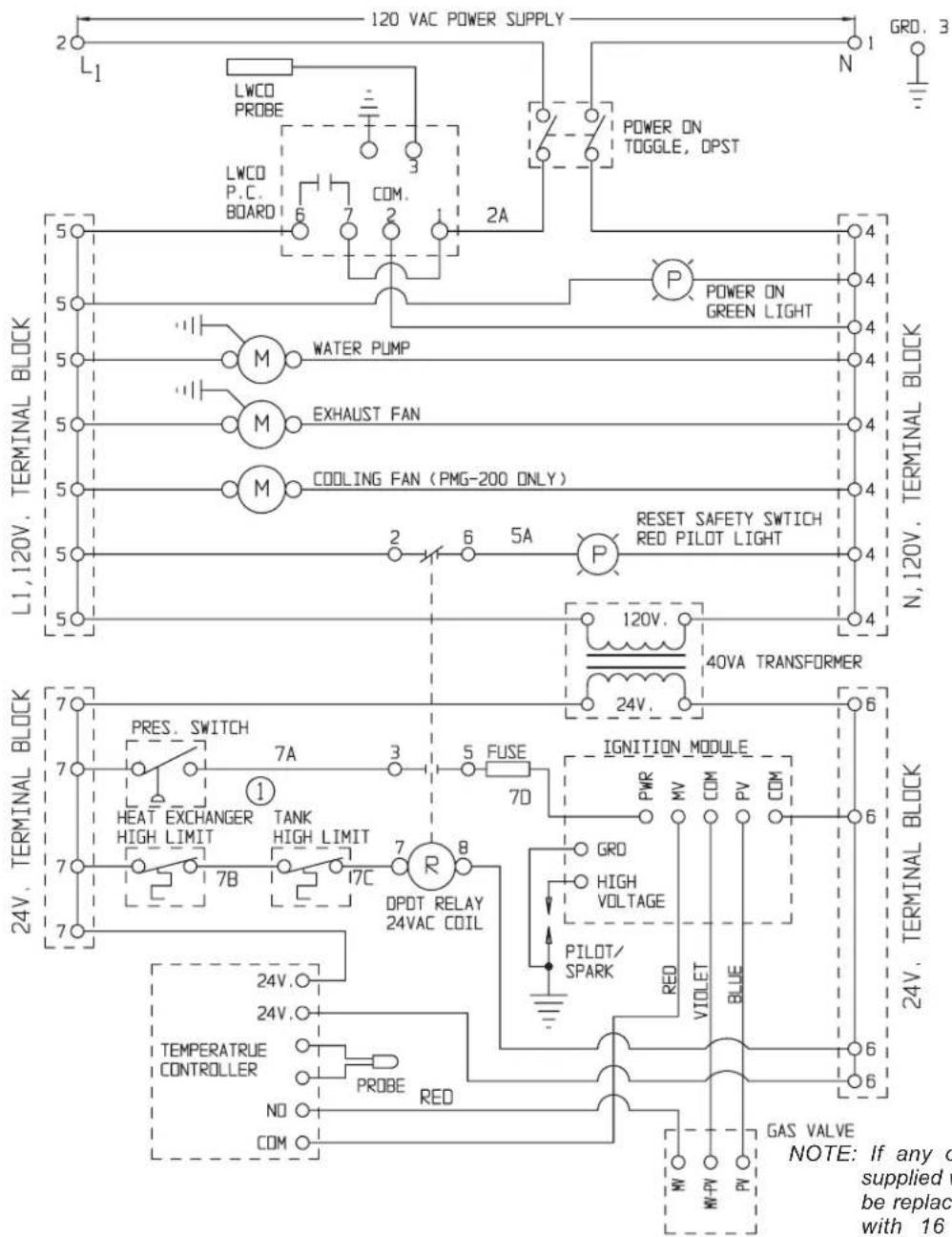
If any of the original wire as supplied with the appliance must be replaced, it must be replaced with 16 AWG 90°C (194°F) wire or its equivalent. For field-wired connections, use No. 16 AWG wires rated for at least 90°C (194°F).
Hatco® Powermite® Gas Booster Water Heaters
Models PMG-100 and PMG-200
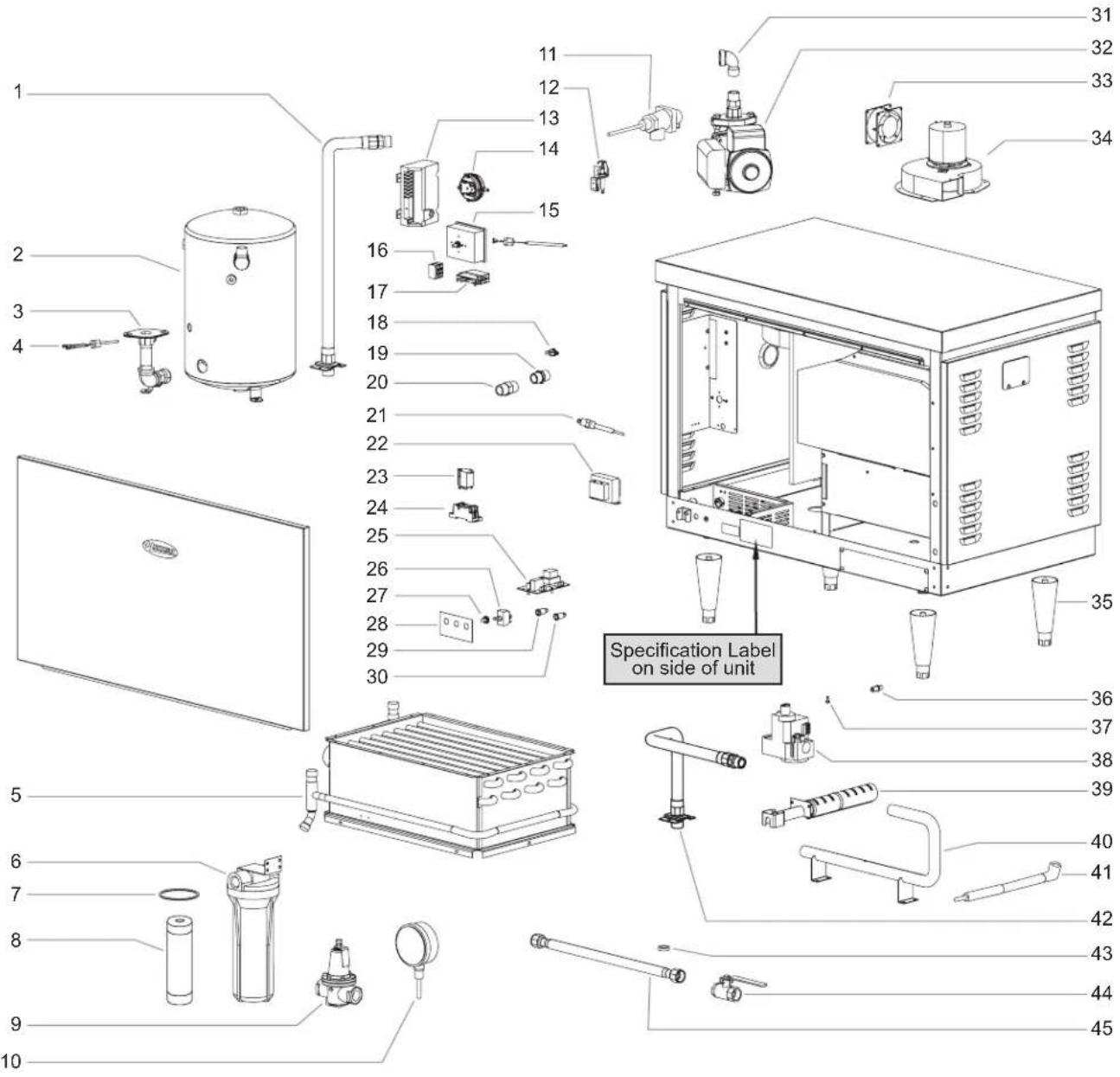

24 Hour 7 Day Parts and Service Assistance available in the United States and Canada by calling 414-671-6350.

Use of replacement parts other than those supplied by Hatco Corporation may result in damage to unit or injury to personnel and will void all warranties.
Parts Common to All PMG-100 and PMG-200 Models
| Item Description Part No. Qty. | ||
| 1 Heat Trap Assembly AS.141.00 1 | ||
| 2 Tempering Tank 01.05.005.00 1 | ||
| 3 Pump Flange Kit with Bolts 03.05.026.00 1 | ||
| 4 Temperature Control Probe R02.16.069.00 1 | ||
| 5 Heat Exchanger (PMG-100) R03.12.013B.00 1 | ||
| Heat Exchanger (PMG-200) R03.12.017B.00 1 | ||
| 6 Water Treat Cartridge and Cannister | 03.05.061.00 1 | |
| 7 O-Ring Gasket 03.05.061B.00 1 | ||
| 8 Cartridge Only 03.05.061A.00 1 | ||
| 9 Reducing Valve | ||
| Iron | 03.02.004.00 1 | |
| Brass | 03.02.015.00 1 | |
| 10 Temperature/Pressure Gauge | 03.01.003.00 | 2 |
| 11 Relief Valve | 03.02.022.00 1 | |
| 12 Pilot Assembly | 03.12.010.00 1 | |
| 13 Ignition Module | R02.21.022.00 1 | |
| 14 Pressure Switch | ||
| PMG-100 | 02.21.027.00 1 | |
| PMG-200 | 02.21.028.00 1 | |
| 15 Control Thermostat with Probe | R02.16.068.00 1 | |
| 16 Sectional T-Block 30P Control | 02.15.032.00 1 | |
| Sectional T-Block 8P Distribution | 02.15.033.00 1 | |
| 17 Tank High Limit, Manual Reset | 02.16.116.00 1 | |
| 18 Heat Exchanger High Limit | 02.16.106.00 1 | |
| 19 3/4" Nipple with Shoulder | 03.06.012.00 | 1 |
| 20 3/4" x 3/4" Hex Nipple | 03.05.057.00 1 | |
| 21 Low Water Cutoff Probe | 02.40.001.00 1 | |
| 22 Transformer 120/24 V (40 VA) | 02.17.034.00 | 1 |
| 23 Relay 24VAC | 02.01.116.00 1 | |
| 24 Socket, Relay | 02.01.125.00 1 | |
| 25 Low Water Cut Off Board 120 V | R02.01.210.00 1 | |
| 26 Toggle Switch DPST | R02.19.008A.00 1 | |
| 27 Boot Cover, Toggle Switch | 02.20.040.00 1 | |
| 28 Control Label | 07.03.248.00 1 | |
| 29 Indicator Light, Green 120 V | 02.19.070G.00 1 | |
| 30 Indicator Light, Red 120 V | 02.19.070R.00 1 | |
| Item Description Part No. Qty. | |||
| 31 | Elbow | 03.08.012.00 2 | |
| 32 | Water Circulating Pump | R03.05.052.00 1 | |
| 33 | Cooling Fan (PMG-200 Only) | 02.12.008A.00 1 | |
| 34 | Exhaust Blower | R02.12.052.00 1 | |
| 35 | 6" (152 mm) Plastic Legs | 05.30.069.00 | 4 |
| 6" (152 mm) Stainless Legs | 05.30.070.00 4 | ||
| 36 | Natural Gas Orifices | ||
| PMG-100 | 03.12.016.00 3 | ||
| PMG-200 | 03.12.020.00 6 | ||
| 37 | LP Conversion Orifice | 03.12.011.00 1 | |
| 38 | Gas Valve | 02.21.025.00 1 | |
| 39 | Burner Tube | 03.12.012.00 | 3–6 |
| 40 | Gas Manifold | ||
| PMG-100 | 03.12.019.00 1 | ||
| PMG-200 | 03.12.015.00 1 | ||
| 41 | Pilot Spark Cable, High Voltage | 02.21.026.00 1 | |
| 42 | Flex Gas Lines | 1 | |
| PMG-100 | 03.12.049.00 | 1 | |
| 03.12.051.00 | 1 | ||
| PMG-200 | 03.12.049.00 2 | ||
| 43 | Water Line Gasket | 05.06.066.00 4 | |
| 44 | Manual Shut Off Valve | 03.02.027.00 1 | |
| 45 | Flexible Water Lines | 03.05.049.00 2 | |
| 46 | Spark Cable * | 02.01.039.00 1 | |
| 47 | LP Gas Valve Conversion Kit * | 02.21.024.00 | 1 |
| 48 | LP Gas Orifice * | 03.12.021.00 | 3–6 |
| 49 | High Altitude Blank Orifice Kit * | R03.12.023.00 | 1 |
| 50 | Straight Exhaust Adapter * | R04.28.052.00 | 1 |
| 51 | Right Angle Exhaust Adapter * | R04.28.053.00 | 1 |
| 52 | Exhaust Outlet Box * | R04.28.077.00 1 | |
| 53 | LP Gas Conversion Kit(includes Items 47 and 48) * | R00.02.0005.00 1 | |
* Not shown.
NOTE: Consult factory if replacing Orifices or Burner Assembly to ensure proper sizing.
NOTE: When calling for parts/service, please supply altitude of installation location and fuel type.
NOTE: The last four digits in a ten digit numerical serial number are the manufacturing date code: 9625062204

Please note also, prior to January 2001 the serial number date code indicated the month of manufacture.
Example: XXXXXX0007
Introduction......28
RISQUE D'INCENDIE OU D'EXPLOSION:
natural_image
Line drawing of a portable industrial control unit with mounting legs and ventilation slots (no text or symbols)PMG-100
continué...
Modèle PMG-200
natural_image
Line drawing of a stainless steel industrial appliance with control panel and mounting feet (no text or symbols)PMG-200
VUE D'ENSEMBLE DU SYSTÈME
RISQUE D'INCENDIE OU D'EXPLOSION:
RISQUE D'INCENDIE OU D'EXPLOSION:
Byassee Equipment Co. Phoenix 602-252-0402
CALIFORNIA
Industrial Electric Commercial Parts & Service, Inc. Huntington Beach 714-379-7100
Chapman Appl. Service San Diego 619-298-7106
P & D Appliance Commercial Parts & Service, Inc. S. San Francisco 650-635-1900
COLORADO
Hawkins Commercial Appliance Englewood 303-781-5548
FLORIDA
Whaley Foodservice Repair Jacksonville 904-725-7800
Whaley Foodservice Repair Orlando 407-757-0851
B.G.S.I./Heritage Pompano Beach 954-971-0456
Comm. Appliance Service Tampa 813-663-0313
GEORGIA
Heritage Service Group Norcross 866-388-9837
HAWAII
Burney's Comm. Service, Inc. Honolulu 808-848-1466
Food Equip Parts & Service Honolulu 808-847-4871
ILLINOIS
Parts Town Addison 708-865-7278
Eichenauer Elec. Service Decatur 217-429-4229
Midwest Elec. Appl. Service Elmhurst 630-279-8000
Cone's Repair Service Moline 309-797-5323
IOWA
Goodwin Tucker Group Des Moines 515-262-9308
KENTUCKY
Tech 24 Lexington 859-254-8854
Tech 24 Louisville 502-451-5411
LOUISIANA
Chandlers Parts & Service Baton Rouge 225-272-6620
MARYLAND
Electric Motor Service Baltimore 410-467-8080
MASSACHUSETTS
Ace Service Co., Inc. Needham 781-449-4220
MICHIGAN
Bildons Appliance Service Detroit 248-478-3320
Commercial Kitchen Service Bay City 989-893-4561
Midwest Food Equip. Service Grandville 616-261-2000
MISSOURI
General Parts Kansas City 816-421-5400
Commercial Kitchen Services St. Louis 314-890-0700
Kaemmerlen Parts & Service St. Louis 314-535-2222
NEBRASKA
Anderson Electric Omaha 402-341-1414
NEVADA
Burney's Commercial Las Vegas 702-736-0006
Hi. Tech Commercial Service N. Las Vegas 702-649-4616
NEW JERSEY
Jay Hill Repair Fairfield 973-575-9145 Service Plus Flanders 973-691-6300
NEW YORK
Alpro Service Co. Maspeth 718-386-2515
Duffy's - AIS Buffalo 716-884-7425
3Wire Plattsburgh 800-634-5005
Duffy's - AIS Sauquoit 800-836-1014
J.B. Brady, Inc. Syracuse 315-422-9271
NORTH CAROLINA
Authorized Appliance Charlotte 704-377-4501
OHIO
Akron/Canton Comm. Svc. Inc. Akron 330-753-6634
Tech 24 Cincinnati 513-772-6600
Commercial Parts and Service Columbus 614-221-0057
Electrical Appl. Repair Service Brooklyn Heights 216-459-8700
E. A. Wichman Co. Toledo 419-385-9121
OKLAHOMA
Hagar Rest. Service, Inc. Oklahoma City 405-235-2184
OREGON
General Parts Group Portland 503-624-0890
PENNSYLVANIA
Elmer Schultz Services Philadelphia 215-627-5401
FAST Comm. Appl. Service Philadelphia 215-288-4800
AIS Commercial Parts and Service Pittsburgh 412-809-0244
K & D Service Co. Harrisburg 717-236-9039
Electric Repair Co. Reading 610-376-5444
RHODE ISLAND
Marshall Electric Co. Providence 401-331-1163
SOUTH CAROLINA
Whaley Foodservice Repair Lexington 803-996-9900
TENNESSEE
Camp Electric Memphis 901-527-7543
TEXAS
Armstrong Repair Service Houston 713-666-7100
Cooking Equipment Specialist Mesquite 972-686-6666
Commercial Kitchen Repair Co. San Antonio 210-735-2811
UTAH
La Monica's Rest. Equip. Service Murray 801-263-3221
VIRGINIA
Daubers Norfolk 757-855-4097
Daubers Springfield 703-866-3600
WASHINGTON
3Wire Seattle 800-207-3146
WISCONSIN
A.S.C., Inc. Madison 608-246-3160
A.S.C., Inc. Milwaukee 414-543-6460
CANADA
ALBERTA
Key Food Equipment Service Edmonton 780-438-1690
BRITISH COLUMBIA
Key Food Equipment Service Vancouver 604-433-4484
Key Food Equipment Service Victoria 250-920-4888
MANITOBA
Air Rite, Inc. Winnipeg 204-895-2300
NEW BRUNSWICK
EMR Services, Ltd. Moncton 506-855-4228
ONTARIO
R.G. Henderson Ltd. Toronto 416-422-5580
Choquette - CKS, Inc. Ottawa 613-739-8458
QUÉBEC
Choquette - CKS, Inc. Montreal 514-722-2000
Choquette - CKS, Inc. Québec City 418-681-3944
UNITED KINGDOM
Marren Group Northants +44(0)1933 665313
HATCO CORPORATION
P.O. Box 340500
Milwaukee, WI 53234-0500 U.S.A.
414-671-6350
support@hatcocorp.com
www.hatcocorp.com
Register your unit online!
See IMPORTANT OWNER INFORMATION section for details.
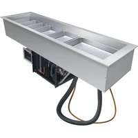
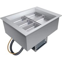
- IMPORTANT OWNER INFORMATION
- Register your unit!
- INTRODUCTION
- Read the following important safety information before using this equipment to avoid serious injury or death and to avoid damage to equipment or property.
- WARNING
- FIRE OR EXPLOSION HAZARD:
- ELECTRIC SHOCK HAZARD:
- CAUTION
- BURN HAZARD:
- NOTICE
- MODEL DESCRIPTION
- All Models
- Model PMG-100
- Model PMG-200
- SPECIFICATIONS
- General
- Code Requirements
- Combustion/Ventilation Air
- High Altitude Installation and Operation
- Altitude Summary Publication Data for PMG Booster Water Heaters
- Plumbing Installation
- Pressure And Temperature Relief Valves
- Temperature/Pressure Gauges
- Pressure Reducing Valve
- Blended Phosphate Water Treatment System
- Plumbing Connections
- Inlet
- Outlet
- Shock Absorber
- Gas Installation
- Components
- Gas Piping
- Gas Installation Diagram
- Electrical Installation
- Electrical Connections
- Venting Installation
- Excerpt From ANSIZ223.1/NFPA #54
- Startup
- What To Do If You Smell Gas:
- To Turn Off Gas To Appliance:
- MAINTENANCE
- Gas Flame
- Burner Removal/Inspection
- Draining The Heat Exchanger
- Component Adjustments/Replacements
- Gas Valve Replacement
- Ignition Module Replacement
- Transformer Replacement
- Temperature Control Probe Replacement.
- Recirculating Pump Replacement
- Temperature/Pressure Gauge Replacement
- Temperature/Pressure Relief Valve Replacement
- Low Water Cut Off Replacement
- Tank High Limit Replacement
- Orifice Replacement (for High Altitude Orifice Size Change or Orifice Repair)
- Vent Outlet Adjustment to Right Side
- Heat Exchanger Replacement
- Blended Phosphate Water Treatment Cartridge Replacement
- WARRANTY, EXCLUSIVE REMEDY:
- One (1) Year Parts and Labor PLUS One (1) Additional Year Parts-Only Warranty:
- Two (2) Year Parts and Labor Warranty:
- One (1) Year Replacement Warranty:
- One (1) Year Parts and Labor PLUS Four (4) Years
- Parts-Only Warranty:
- One (1) Year Parts and Labor PLUS Nine (9) Years Parts-Only Warranty:
- Ninety (90) Day Parts-Only Warranty:
- WARRANTY REGISTRATION INSTRUCTIONS:
- LIMITATION OF LIABILITY:
- Hatco® Powermite® Gas Booster Water Heaters
- Models PMG-100 and PMG-200
- RISQUE D'INCENDIE OU D'EXPLOSION:
- Modèle PMG-200
- VUE D'ENSEMBLE DU SYSTÈME
- CALIFORNIA
- COLORADO
- FLORIDA
- GEORGIA
- HAWAII
- ILLINOIS
- IOWA
- KENTUCKY
- LOUISIANA
- MARYLAND
- MASSACHUSETTS
- MICHIGAN
- MISSOURI
- NEBRASKA
- NEVADA
- NEW JERSEY
- NEW YORK
- NORTH CAROLINA
- OHIO
- OKLAHOMA
- OREGON
- PENNSYLVANIA
- RHODE ISLAND
- SOUTH CAROLINA
- TENNESSEE
- TEXAS
- UTAH
- VIRGINIA
- WASHINGTON
- WISCONSIN
- CANADA
- ALBERTA
- BRITISH COLUMBIA
- MANITOBA
- NEW BRUNSWICK
- ONTARIO
- QUÉBEC
- UNITED KINGDOM
Brand : Hatco
Model : CWBP-6
Category : Refrigerator