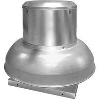
HVA24T10075 - Fan Canarm - Free user manual and instructions
Find the device manual for free HVA24T10075 Canarm in PDF.


| Product Type | Wall-mounted exhaust or supply fan |
| Brand | Canarm |
| Model | HVA24T10075 |
| Dimensions (A x B x C) | A: 30 7/8 in (78.5 cm), B: 26 in (66 cm), C: 32 in (81.3 cm) (for 24 in model) |
| Weight | Not specified in the manual |
| Power supply | Match the voltage on the motor nameplate (typically 115V or 208-230V, 1 or 3 phases) |
| Main functions | Air exhaust or supply, with motorized damper (optional), belt drive, reversible direction (ADDR/HVAR models) |
| Safety | Protection required if mounted less than 2 m from the ground; cut power before maintenance; installation by certified electrician |
| Maintenance and cleaning | Semi-annual lubrication of bearings (lithium grease); check belt tension and alignment; clean dust from motor, panel and wheel |
| Spare parts and repairability | Belts, pulleys, bearings, impellers, motor (Canarm parts) |
| General information | 1-year warranty (parts); manufactured by Canarm Ltd.; consult manual for detailed installation |
Frequently Asked Questions - HVA24T10075 Canarm
User questions about HVA24T10075 Canarm
0 question about this device. Answer the ones you know or ask your own.
Ask a new question about this device
Download the instructions for your Fan in PDF format for free! Find your manual HVA24T10075 - Canarm and take your electronic device back in hand. On this page are published all the documents necessary for the use of your device. HVA24T10075 by Canarm.
USER MANUAL HVA24T10075 Canarm
WALL EXHAUST FANS BELT & DIRECT DRIVE
CANARM HVAC
INSTALLATION AND MAINTENANCE INSTRUCTIONS READ AND SAVE THESE INSTRUCTIONS
Models: XB, HV, HVA, HVAR, ADD, ADDR, DDS, DDP, SXB, SADD
THE PURPOSE OF THIS MANUAL IS TO AID IN THE PROPER INSTALLATION AND OPERATION OF THE FANS. THESE INSTRUCTIONS ARE INTENDED TO SUPPLEMENT GOOD GENERAL PRACTICES AND ARE NOT INTENDED TO COVER DETAILED INSTRUCTION PROCEDURES. IT IS THE RESPONSIBILITY OF THE PURCHASER TO ASSURE THAT THE INSTALLATION AND MAINTENANCE OF THIS EQUIPMENT IS HANDLED BY QUALIFIED PERSONNEL.
Inspect all shipments carefully for damage. THE RECEIVER MUST NOTE ANY DAMAGE ON THE CARRIER'S BILL OF LADING AND FILE A CLAIM IMMEDIATELY WITH THE FREIGHT COMPANY.
ELECTRICAL CONNECTIONS

WARNING: BE SURE POWER IS OFF AT THE ELECTRICAL PANEL BEFORE WIRING.
WARNING: ALL ELECTRICAL WORK SHOULD BE PERFORMED BY A QUALIFIED ELECTRICIAN.
INSTALLATION
- Cut and frame the appropriate wall opening. Fans mounted to a wall require a different wall opening than fans mounted in cabinets or sleeves. For specific dimensions, refer to the submittal drawing for the specific fan configuration.
- Mount the fan in the opening with the fan panel directly over the load bearing support and if this is not practical angle supports must be provided to transfer the fan weight to the load bearing structure.
- Caution: The fan contains rotating parts and requires electrical service. Appropriate safety precautions should be taken during installation, operation and maintenance.
- Warning: Do not install or operate this fan in an environment where combustible materials, gasses or fumes are present unless it was specifically designed and manufactured for that application.
- A damper, if used, should be securely mounted in a manner that allows free and unobstructed operation.
- All electrical work must be done, in accordance with all applicable electrical codes, by a qualified electrician. Please follow all applicable national, state/provincial and local codes, all of them will supersede this manual.
- Prior to wiring ensure the power supply is locked in the OFF position and that the motor nameplate voltage and the supply voltage match.
- Be sure to keep all wiring clear of any rotating parts.
- Before starting the fan ensure that the wheel rotates freely.
M0112_NOV 2020 Page 1 of 8WWW.CANARM.COM
INSTALLATION CONTINUED
- Tighten all nuts, bolts and setscrews prior to fan start up (as some may have loosened during shipping).
- On belt driven fans make sure that the belts are tensioned and aligned correctly.
- Ensure that all protective guards and other safety devices are installed properly prior to fan start up.
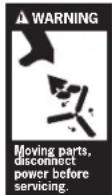
WARNING: GUARDING SHOULD BE USED IF FANS ARE MOUNTED LOWER THAN SEVEN FEET (2 METRES) OFF FLOOR OR GROUND LEVEL.
STANDARD WIRING INSTRUCTIONS
- A qualified electrician in accordance with all local and National Electrical Codes should do all wiring.
- Lock off all power sources before any wiring is to be performed.
- Leave enough slack in the wiring to allow for motor movement when adjusting the belt tension.
- Excess wire must be restrained in order to prevent it from entering the shaft and propeller area.
- Disconnect switches are recommended and should be located near the fan in order to, swiftly cut off power in case of an emergency and maintain complete control of the power source.
- Some motors may have to be removed in order to make the connections in the motor terminal box.
- Follow the wiring diagrams on the motor nameplate.
1. Wall Fans
- Extend the proper gauge wire to the fan motor.
- Restrain excess wire from entering the shaft and propeller area
2. Wall Fans with Cabinets
- Remove guard from cabinet.
- Drill a hole through the cabinet at a convenient location and pull the wires through (never wire through the guard).
- Restrain excess wire from entering the shaft and propeller area
OPERATION
Pre Start Inspection
- Lock out all power sources
- Inspect all fasteners and set screws and tighten as required
- Inspect belt alignment and tension
- Confirm power source voltage and motor voltage are the same and that the motor is wired correctly
- Rotate the fan blade to ensure that neither the fan blade nor the belts come into contact with the housing
- Inspect the fan and the ductwork to ensure they are free of debris
- Check to ensure that all guards and accessories are securely mounted
- Check to be sure the propeller rotation is correct
M0112_NOV 2020 Page 2 of 8WWW.CANARM.COM
OPERATION CONTINUED
Typical Installation - Refer to page 7
Start Up
Turn the fan on and inspect for the following.
- Direction of rotation
- Improper motor amperage
- Excessive Vibration
- Unusual Noise
- Improper belt tension or alignment
If a problem is discovered shut off the fan and refer to the section on troubleshooting to discover the cause of the problem. The fan should be inspected after 30 minutes, 8 hours and 24 hours of operation to ensure all fasteners are tight and belts are properly tensioned and aligned.
MAINTENANCE WARNING
Disconnect and secure to the OFF position all electrical power to the fan prior to inspection or servicing. Failure to comply with this safety precaution could result in serious injury or death.
- Ventilators should be checked at least once a year. For critical or severe applications a routine check every two to three months is suggested.
- When removing or installing a belt don't force the belt over the sheave. Loosen the motor mount so that the belt can be easily slipped over the sheave.
- The belt, on belt driven units, should be removed and carefully checked for cracks, ply separation or irregular wear. A small irregularity in the contact surface of the belt will result in noisy operation. If any of these defects are apparent the belt should be replaced. At the same time check the sheaves for chips, dents or rough surfaces that could damage the belt.
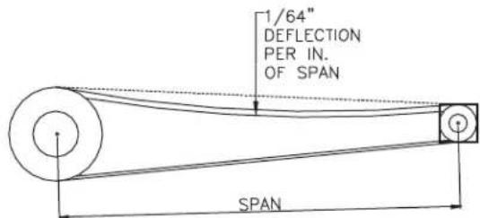
- The correct belt tension is important. Too tight a belt will result in excess bearing pressure, which can cause premature bearing failure and may cause the motor to overload, too loose a belt will result in slippage, which will burn out belts. Proper belt deflection should be 1/64" (half way between sheave centers) for each inch of belt span when a force of approximately 5 lbs. is applied.
- The belt alignment should be checked to be sure that the belt is running perpendicular to the rotating shafts. Motor and drive shafts must be parallel.
- A periodic inspection of all fasteners should be carried out to ensure they have not loosened due to vibration. Particular attention should be paid to fasteners attaching the wheel to the shaft and those attaching the shaft to the bearing.
- The standard pillow blocks on belt driven fans are factory lubricated. These bearings should be lubricated on a semi annual basis (more frequently in severe applications) using a high quality lithium based grease. With the unit running add grease very slowly, using a manual grease gun, until a slight bead of grease forms at the seal. Be careful not to unseat the seal by over lubricating or by using excessive pressure. When the bearings are obstructed from view use no more than three injections with a hand operated grease gun.
- Dust and dirt on the exterior surface of the motor, fan panel and the entire fan wheel should be removed, at intervals determined by the severity of the application, to ensure proper service life and safety.
- For additional safety information refer to AMCA publication 410-96, Safety Practices for Users and Installers of Industrial and Commercial Fans
M0112_NOV 2020 Page 3 of 8WWW.CANARM.COM
Belt Tension
BELT AND PULLEY REPLACEMENT
In the course of regular maintenance the belts and pulleys may have to be changed and or adjusted the recommended procedure is as follows.
- Do not change the pulley pitch diameter in order to tension the belts. This will result in a change in the fan speed.
- Loosen the nuts on the motor plate or motor in order to reduce the belt tension such that the belts will easily slip over the pulleys. Never force the belts over the rim of the pulley.
Loosen the setscrews on the pulleys and remove from either the motor or fan shaft using a two or three jaw puller. - Remove any shaft imperfection such as setscrew mark using a file or emery cloth.
- Install the replacement pulleys tightening all setscrews to the recommended torque rating (see chart) and ensuring that they are properly aligned.
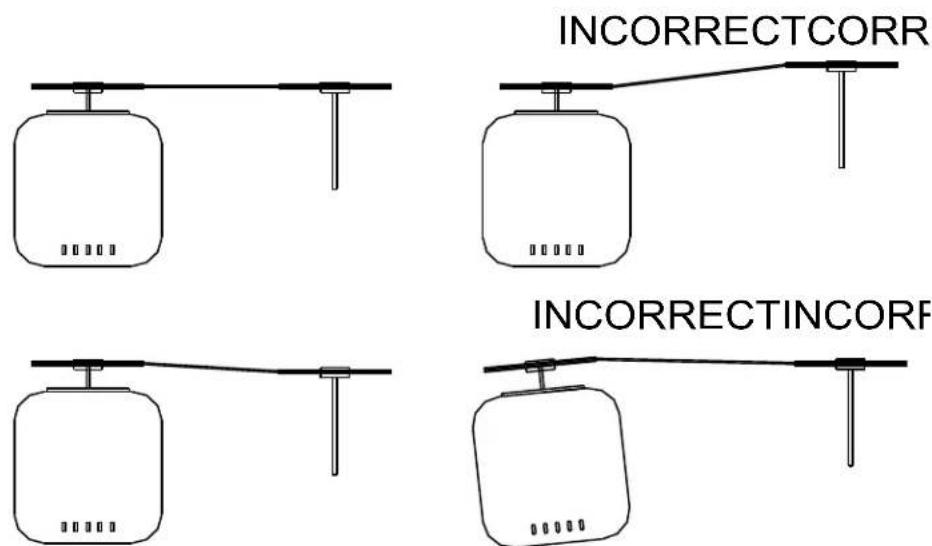
- Pulley alignment is achieved by moving the pulleys on their respective shafts or moving the entire motor until the pulleys are correctly aligned (see figure). Using a square with one edge parallel to the motor shaft adjust the pulleys until the other edge is parallel to the belts.
- Slip the belts over the pulleys then adjust the motor/ motor plate until the proper tension is reached (1/64" deflection, half way between pulley centers, per inch of belt span when pressed firmly).
- Tighten the motor plate/ motor adjusting nuts in place.
PULLEY ALIGNMENT
M0112_NOV 2020 Page 4 of 8WWW.CANARM.COM
REplacement
Canarm Ltd. uses pillow block bearings.
Before removing the bearings mark the positions of the fan blade, bearings and pulley on the shaft.
Note the clearance between the fan blade and the venturi.
- Remove the pulley and fan blade from the shaft using a puller.
- Unbolt the bearings and remove the shaft and pillow blocks as one unit.
- Clean the shaft and remove any marks using a file or emery cloth then remove the bearings using a bearing puller.
- Inspect the shaft and replace if necessary.
- Mount the new bearings on a section of the shaft that is not worn by tapping the inner ring face using a soft mallet.
Align the setscrews on the bearings and then tighten one setscrew on each bearing.
- Loosely install the bearings on the bearing mount.
- Rotate the shaft to find the center of free movement.
Install the propeller adjusting the bearing location to center the blade in the venturi.
- Tighten the bearing bolts to the proper torque rating
- Turn the propeller by hand the propeller should rotate freely with the same resistance as before the bearing bolts were tightened.
- Tighten all setscrews to the proper torque rating
Install pulley and adjust belt tension.
You should go through the start up steps as outlined above.
PARTS LIST
MODELS: DDS, DDP, ADD, ADDR
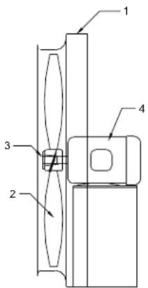
FAN ASSEMBLY
| ITEM | DESCRIPTION QUANTITY | |
| 1 | WELDED FAN ASSEMBLY | 1 |
| 2 | PROPELLER | 1 |
| 3 | PROPELLER BUSHING | 1 |
| 4 | MOTOR 1 |
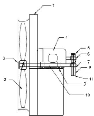
MODELS: XB, HV, HVA, HVAR
FAN ASSEMBLY
| ITEM | DESCRIPTION | QUANTITY |
| 1 | 1WELDED | |
| 2 | PROPELLER | 1 |
| 3 | PROPELLER BUSHING | 1 |
| 4 | MOTOR | 1 |
| 5 | MOTOR SHEAVE | 1 |
| 6 | MOTOR SHEAVE BUSHING | 1 |
| 7 | DRIVEN SHEAVE BUSHING | 1 |
| 8 | DRIVEN SHEAVE | 1 |
| 9 | PILOW BLOCK BEARINGS | 2 |
| 10 | FAN SHAFT | 1 |
| 11 | “V” BELTS | 2 |
M0112_NOV 2020 Page 5 of 8WWW.CANARM.COM
FAN TROUBLE SHOOTING GUIDE
PROBLEM
POSSIBLE CAUSES
Impeller or sheaves loose
Belts not tensioned properly
Bent shaft
VIBRATION
Out of balance impeller
Loose fasteners
Loose or worn bearings
Drive misalignment
Fan not properly installed
Mismatched belts
Out of balance sheaves
Improper fan installation
MOTOR OVERLOADING
Static pressure higher than design
Impeller rotating in the wrong direction
Improper fan speed
Defective motor
Fan speed higher than design
TOOMUCHAIR
Filters missing
Static pressure lower than design
Fan speed higher than design
FAN DOES NOT OPERATE
Lack of electricity to the fan
Fan wired improperly
Broken or missing belt
Missing or blown fuses
Overload protection has broken circuit
Defective motor
EXCESSIVE NOISE
Impeller or sheaves loose
Belts not properly tensioned
Sheaves not properly aligned
Impeller out of balance
Sheaves out of balance
Bent shaft
Bearings defective or need lubrication
Worn belts
Vibration or lack of isolation
Loose fasteners
High velocity air
TYPICAL INSTALLATIONS
Wall exhaust fan with cabinet, back guard and shutter
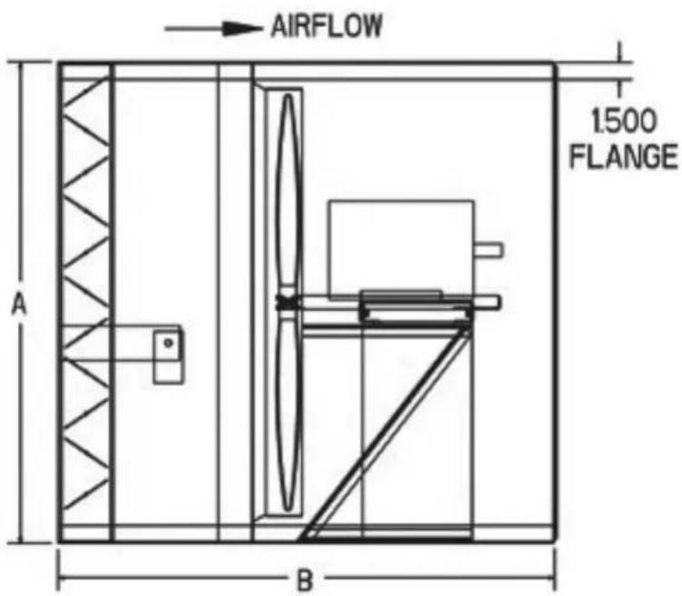
The drawing below illustrates the typical installation of an exhaust fan with cabinet, back guard and shutter in a masonry wall. The installer shall provide angle iron framing and suitable fasteners (hex bolts or lag screws) to support the fan. The cabinet and framing should be caulked to the exterior wall. Fans with motors in excess of 50 pounds should also be supported using hanging rods or by supports placed underneath the fan.
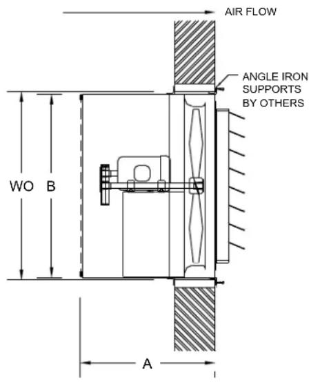
EXHAUST WALL FAN C/W CABINET, SHUTTER AND BACKGUARD
| XB,HV,HVA,HVAR | DDS,DDP,ADD | WO | A | B |
| - | 12 | 17 1/4 | 16 | 16 1/4 |
| - | 14 | 19 1/4 | 16 | 18 1/4 |
| - | 16 | 21 1/4 | 16 | 20 1/4 |
| - | 18 | 23 1/4 | 16 | 22 1/4 |
| - | 20 | 25 1/4 | 16 | 24 1/4 |
| 24 | 24 | 30 7/8 | 26 | 29 7/8 |
| 30 | 30 | 36 7/8 | 26 | 35 7/8 |
| 36 | 36 | 42 7/8 | 26 | 41 7/8 |
| 42 | 42 | 48 7/8 | 26* | 47 7/8 |
| 48 | 48 | 54 7/8 | 26* | 53 7/8 |
| 54 | - | 60 7/8 | 26*+ | 59 7/8 |
| 60 | - | 69 | 26*+ | 68 |
- For 7 1/2 hp and 10 hp add 6"
- For 15 hp and 20 hp add 8"
Wall supply fan with cabinet, back guard, motorized shutter and weather hood
The drawing below illustrates the typical installation of a supply fan with a cabinet, back guard, motorized shutter (with end switch), and weather hood in a masonry wall. The installer shall provide angle iron framing and suitable fasteners (hex bolts or lag screws) to support the fan. The cabinet and framing should be caulked to the exterior wall. The weather hood can either be attached to the cabinet or fastened to the wall and then caulked. These fans should either be supported by hanging rods or by supports placed underneath the fan.
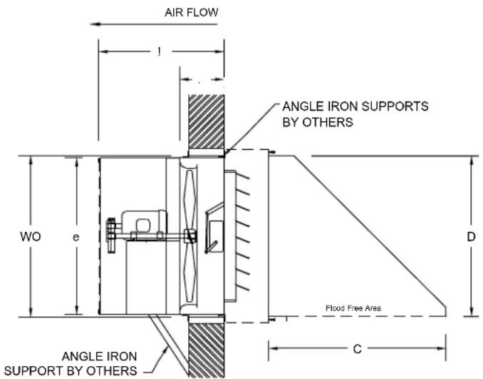
SUPPLY WALL FAN C/W EXT, CABINET BACKGUARD, MOTORIZED 3200 SER, SHUTTER AND WALL HOOD
| XB,HV,HVA,HVAR | DDS,DDP,ADD,ADDR | WO | A | B | C | D | E |
| - | 12 | 17 1/4 | 22 | 11 | 20 1/2 | 16 1/2 | 16 1/4 |
| - | 14 | 19 1/4 | 22 | 11 | 22 1/2 | 18 1/2 | 18 1/4 |
| - | 16 | 21 1/4 | 22 | 11 | 24 1/2 | 20 1/2 | 20 1/4 |
| - | 18 | 23 1/4 | 22 | 11 | 26 1/2 | 22 1/2 | 22 1/4 |
| - | 20 | 25 1/4 | 22 | 11 | 28 1/2 | 24 1/2 | 24 1/4 |
| 24 | 24 | 30 7/8 | 32 | 14 1/2 | 34 | 30 | 29 7/8 |
| 30 | 30 | 36 7/8 | 32 | 14 1/2 | 40 1/4 | 36 1/4 | 35 7/8 |
| 36 | 36 | 42 7/8 | 32 | 14 1/2 | 46 1/4 | 42 1/4 | 41 7/8 |
| 42 | 42 | 48 7/8 | 32* | 14 1/2 | 52 1/2 | 48 1/2 | 47 7/8 |
| 48 | 48 | 54 7/8 | 32* | 14 1/2 | 58 1/2 | 54 1/2 | 53 7/8 |
| 54 | - | 60 7/8 | 38+ | 20 1/2 | 65 1/4 | 61 | 59 7/8 |
| 60 | - | 69 | 38+ | 20 1/2 | 73 1/4 | 69 | 68 |
- For 7 1/2 hp and 10 hp add 6"
+For 15 hp and 20 hp add 8^
Wall supply fan with steel control damper, cabinet and back guard
ADDR & HVAR FANS
Please note for the reversing models ADDR, HVAR, the supplied reversing switch should be wired in accordance with the instructions supplied by the manufactures of the switch.
The blade should come to a complete stop before switching direction. Failure to do so may cause damage to the motor and/or blade.
For trouble shooting and electrical guidelines, the above instructions apply.
WARRANTY
CANARM Ltd. warrants every new fan to be free of defects in materials and workmanship, to the extent that, within a period of one year from the date of purchase CANARM Ltd. shall either repair or replace at CANARM's option, and unit or part thereof, returned freight prepaid, and found to be defective.
This warranty does not include any labour or transportation cost incidental to the removal and reinstallation of the unit at the user's premises.
Components repaired or replaced are warranted through the remainder of the original warranty period only.
This warranty applies to the original purchaser-user only; it is null and void in case of altercation, accident, abuse, neglect and operation not in accordance with instructions.
NOTICE: No warranty claims will be honored by CANARM Ltd. unless prior authorization is obtained.
Installation or Product problems? Do not return to store of purchase. Contact Canarm Service at 1-800-265-1833 (CANADA) 1-800-267-4427 (U.S.A) 1-800-567-2513 (EN FRANÇAIS) Monday to Friday 8:00am - 5:00pm EST
M0112_NOV 2020 Page 8 of 8WWW.CANARM.COM
VENTILATEUR D'ÉCHAPPEMENT MURAL À COURROIE ET ENTRAJINEMENT DIRECT
CANARM HVAC
INSTRUCTIONS POUR L'INSTALLATION ET LA MAINTENANCE LISEZ ET CONSERVEZ CES INSTRUCTIONS
MODELES : XB, HV, HVA, HVAR, ADD, ADDR, DDS, DDP, SXB, SADD
LE BUT DE CE MANUEL EST D'AIDER À L'INSTALLATION ET AU BON FONCTIONNEMENT DES VENTILATEURS. CES INSTRUCTIONS SONT DESTINÉES À COMPLÉTER LES BONNES PRATIQUES GÉNÉRALES ET NE SONT PAS DESTINÉES À REMPLACER DES PROCÉDURES D'INSTRUCTION DÉTAILLÉES. IL EST DE LA RESPONSABILITÉ DE L'ACHETEUR DE S'ASSURER QUE L'INSTALLATION ET LA MAINTENANCE DE CET ÉQUIPEMENT SONT GÉRÉES PAR UN PERSONNEL QUALIFIÉ.
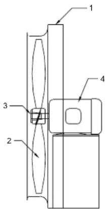
MODELES: DDS, DDP, ADD, ADDR
ASSEMBLAGE DU VENTILATEUR
| PRODUIT | DESCRIPTION QUANTITÉ | |
| 1 | ASSEMBLE DONVIENTATEURSOUÉ | 1 |
| 2 | HÉLICE | 1 |
| 3 | BAGUE D'HÉLICE | 1 |
| 4 | MOTEUR | 1 |
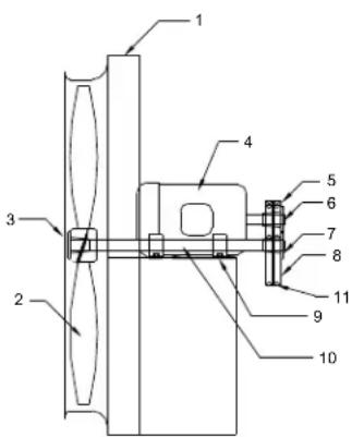
MODELES:XB,HV,HVA,HVAF
ASSEMBLAGE DU VENTILATEUR
| PRODUIT | DESCRIPTION | QUANTITÉ |
| 1 | ASSEMBRADEDUNVENTURESOUDE | 1 |
| 2 | HELICE | 1 |
| 3 | BAGUE D'HELICE | 1 |
| 4 | MOTEUR | 1 |
| 5 | RÉA DU MOTEUR | 1 |
| 6 | BAGUE DU RÉA DU MOTEUR | 1 |
| 7 | BAGUE DU RÉA MOTRICE | 1 |
| 8 | RÉA MOTRICE | 1 |
| 9 | PALLIER ROULEMENT | 2 |
| 10 | ARBRE DU VENTILATEUR | 1 |
| 11 | COURROIE EN "V" | 2 |