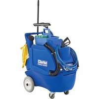
TFC 400 - Pressure washer Clarke - Free user manual and instructions
Find the device manual for free TFC 400 Clarke in PDF.


| Product type | High pressure cleaner |
| Brand | Clarke |
| Model | TFC 400 |
| Intended Use | Commercial (hotels, schools, hospitals, factories, shops, offices) |
| Power supply | 120 V AC, 60 Hz (nominal circuit) |
| Dimensions (H x W x D) | 38.5 x 21.25 x 34 inches |
| Weight | 92 lb |
| Solution tank | 20 gallons (76 L) |
| Recovery tank | 13 gallons (49 L) |
| Operating pressure | 400 psi |
| Suction motor | 2 stages, 8 A, 97 inches of water lift, 100 CFM |
| Hose length (solution and suction) | 25 ft (7.6 m) each |
| Power cord length | 25 ft (7.6 m) with GFCI |
| Maximum water temperature | 54 °C (120 °F) |
| Allowed chemicals | pH between 4 and 12, via siphon system only |
| Routine maintenance | Flush hoses after each use, clean filters weekly, check brushes annually |
| Safety | Grounding required, use antifreeze in freezing conditions, do not operate without priming |
| Parts and service | Contact Clarke for repairs with original parts |
Frequently Asked Questions - TFC 400 Clarke
User questions about TFC 400 Clarke
0 question about this device. Answer the ones you know or ask your own.
Ask a new question about this device
Download the instructions for your Pressure washer in PDF format for free! Find your manual TFC 400 - Clarke and take your electronic device back in hand. On this page are published all the documents necessary for the use of your device. TFC 400 by Clarke.
USER MANUAL TFC 400 Clarke
natural_image
Technical line drawing of a mechanical device with wheels and internal components (no text or symbols)Instructions For Use - Original Instructions / Instrucciones de uso / Mode d'emploi Model: 56380773

READ THIS BOOK
LEA ESTE MANUAL
LISEZ CE MANUEL
EN English (A2 - A8)
ES Español (B2 - B8)
FR Français (C2 - C8)
Parts List (D2-D12)
This book has important information for the use and safe operation of this machine. Failure to read this book prior to operating or attempting any service or maintenance procedure to your Clarke machine could result in injury to you or to other personnel; damage to the machine or to other property could occur as well. You must have training in the operation of this machine before using it. If your operator(s) cannot read this manual, have it explained fully before attempting to operate this machine.
All directions given in this book are as seen from the operator's position at the rear of the machine.
IMPORTANT SAFETY INSTRUCTIONS
This machine is only suitable for commercial use, for example in hotels, schools, hospitals, factories, shops and offices other than normal residential housekeeping purposes.
When using any electrical appliance, basic precautions should always be followed, including the following:
NOTE: Read all instructions before using this machine.

WARNING!
To reduce the risk of fire, electric shock, or injury:
- This machine is not intended for use by persons (including children) with reduced physical, sensory or mental capabilities, or lack of experience and knowledge.
- Always use the power cord that comes with the machine and includes a GFCI (Ground Fault Circuit Interrupter). Never use the machine without connecting to power through a GFCI.
- Do not leave the machine when it is plugged in. Unplug the unit from the outlet when not in use and before servicing.
• To avoid electric shock, do not expose to rain or snow. Store and use indoors. - Do not allow to be used as a toy. Close attention is necessary when used near children.
- Use only as described in this manual. Use only the manufacturer's recommended attachments.
- Do not use with a damaged cord or plug. If the appliance is not working as it should, has been dropped, damaged, left outdoors, or dropped into water, return it to a service center.
- Do not pull by the cord, use the cord as a handle, damage the cord, or allow the cord or the machine near heated surfaces.
- Do not unplug by pulling on the cord. To unplug, grasp the cord end.
- Do not handle the plug, the cord, or the machine with wet hands.
- Do not put any objects into openings. Do not use with any opening blocked; keep free of dust, lint, hair, and anything that may reduce air flow.
- Keep loose clothing, hair, fingers, and all parts of your body away from the openings and moving parts.
- Do not pick-up anything that is burning or smoking, or any health endangering dusts.
• Turn off all controls before unplugging. - Always use chemicals with a pH between 4 and 12, and never introduce the chemicals in the tank. Always use the chemical siphoning system.
• Use extra care when cleaning on stairs. - Do not use to pick up flammable or combustible liquids, and do not use in any areas where these may be present.
- If foam or liquid comes out with the vacuum exhaust, switch the power off immediately. Verify that there are not foreign objects from preventing the float ball from moving freely. Contact Clarke if the problem persists.
- Liquid ejected at the spray nozzle could be dangerous as a result of its temperature, pressure, or chemical content.
SAVE THESE INSTRUCTIONS

WARNING!
The Products sold with this Manual contain or may contain chemicals that are known to certain governments (such as the State of California, as identified in its Proposition 65 Regulatory Warning Law) to cause cancer, birth defects or other reproductive harm. In certain locations (including the State of California) purchasers of these Products that place them in service at an employment job site or a publicly accessible space are required by regulation to make certain notices, warnings or disclosures regarding the chemicals that are or may be contained in the Products at or about such work sites. It is the purchaser's responsibility to know the content of, and to comply with, any laws and regulations relating to the use of these Products in such environments. The Manufacturer disclaims any responsibility to advise purchasers of any specific requirements that may be applicable to the use of the Products in such environments.
INTRODUCTION
This manual will help you to get the most from your Clarke All Purpose Cleaner. Read it thoroughly before operating the machine. This product is intended for commercial use only.
PARTS AND SERVICE
Repairs, when required, should be performed by Clarke service personnel using original replacement parts and accessories. Call Clarke for repair parts or service. Please specify the Model and Serial number when calling about your machine.
MODIFICATIONS
Modifications and additions to the cleaning machine which affect capacity and safe operation shall not be performed by the customer or user without prior written approval from Nilfisk-Advance Inc. Unapproved modifications will void the machine warranty and make the customer liable for any resulting accidents.
NAME PLATE
The model and serial number of your machine are shown on the Name Plate on the machine. This information is needed when ordering parts for the machine. Use the space below to note the model and serial numbers of your machine.
MODEL NUMBER/NAME:
SERIAL NUMBER:
UNPACKING
When the machine arrives, carefully inspect the shipping carton and the machine for damage. If damage is evident, save the shipping carton so that it can be inspected by the carrier. Contact the Clarke customer service department immediately to file a freight damage claim.
DO NOT OPERATE THE MACHINE UNTIL YOU HAVE READ THIS SECTION
IMPROPER USE WILL VOID THE WARRANTY
• Always use a defoamer when foaming occurs to prevent vacuum motor damage.
• To keep fittings, pumps, and lines from damage during freezing conditions, use RV anti-freeze in the pump or keep the machine inside heated areas.
• Do not let the pump run dry.
• All chemicals should be added through the feed system and NOT in the tank.
- All extension cords must have a rating of at least 12/3 (12 gauge cord). Extension cords should be no longer than 50 feet. Replace the plug immediately if the ground prong becomes damaged or is broken off.
• DO NOT use water heated to greater than 120 °F (54 °C).
120VAC GROUNDING INSTRUCTIONS
This appliance must be grounded. If it should electrically malfunction, grounding provides a path of least resistance for electric current to reduce the risk of electric shock. This appliance is equipped with a cord having an equipment-grounding conductor and grounding plug. The plug must be plugged into an appropriate outlet that is properly installed and grounded in accordance with all local codes and ordinances.
DANGER!
Improper connection of the equipment-grounding conductor can result in a risk of electric shock. Check with a qualified electrician or service person if you are in doubt as to whether the outlet is properly grounded. Do not modify the plug provided with the appliance. If it will not fit the outlet, have a proper outlet installed by a qualified electrician.
This appliance is for use on a nominal 120-volt circuit, and has a grounding plug that looks like the plug illustrated in Figure 1 below. A temporary adapter illustrated in Figures 2 and 3 may be used to connect this plug to a 2-pole receptacle as shown in Figure 2 if a properly grounded outlet is not available. The temporary adapter should be used only until a properly grounded outlet (Figure 1) can be installed by a qualified electrician. The green-colored rigid ear, tab, or the like extending from the adapter must be connected to a permanent ground such as a properly grounded outlet box cover. Whenever the adapter is used, it must be held in place by a metal screw. Grounding adapters are not approved for use in Canada.
Replace the plug if the grounding pin is damaged or broken.
The Green (or Green/Yellow) wire in the cord is the grounding wire. When replacing a plug, this wire must be attached to the grounding pin only. Extension cords connected to this machine should be 12 gauge, three-wire cords with three-prong plugs and outlets. DO NOT use extension cords more than 50 feet (15 m) long.
PLEASE NOTE: FOR NORTH AMERICA ONLY
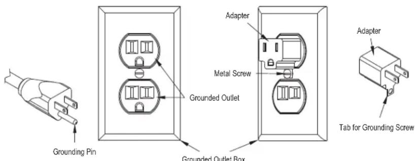
FIGURE 1
FIGURE 2
FIGURE 3
KNOW YOUR MACHINE DESCRIPTIONS
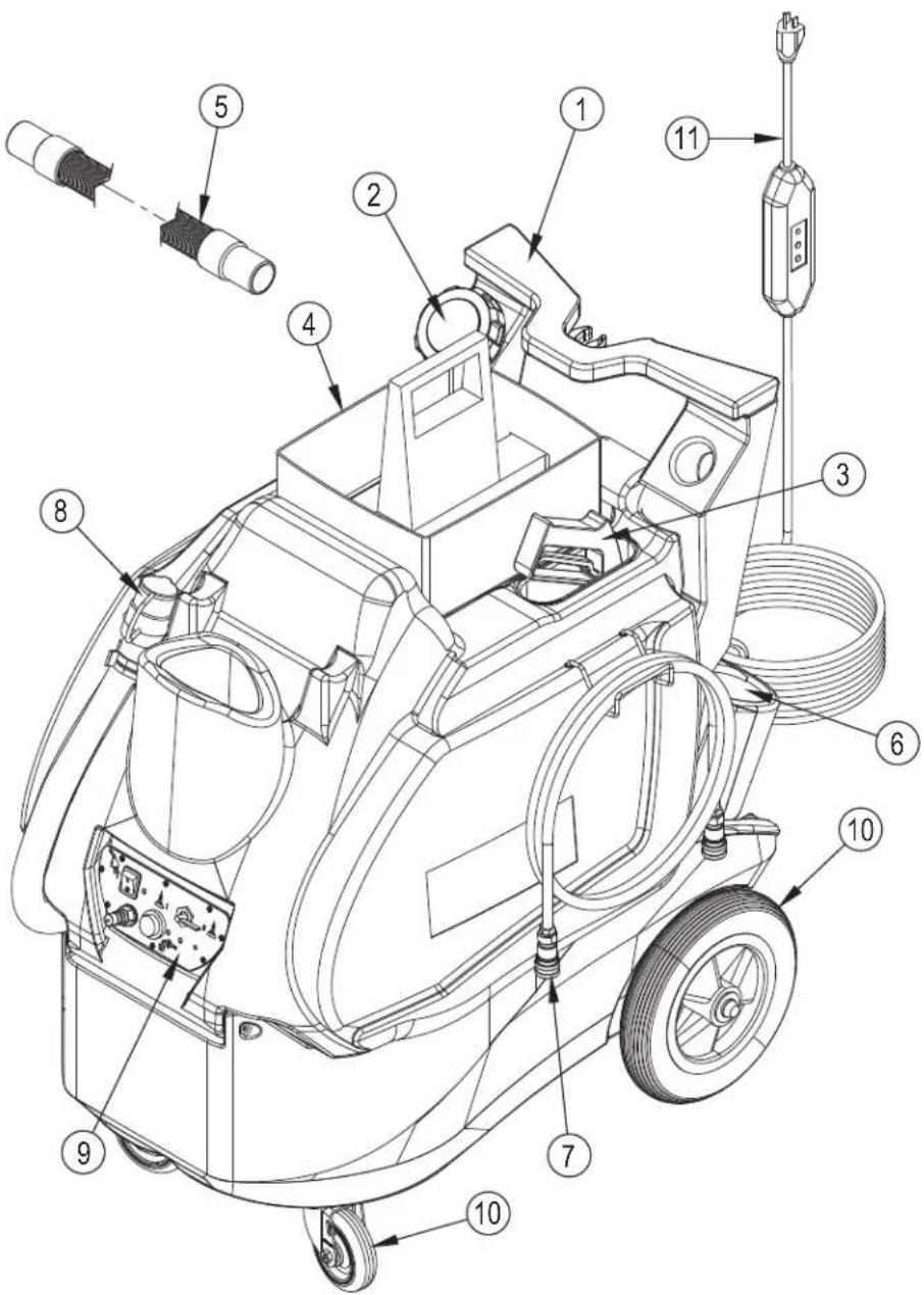
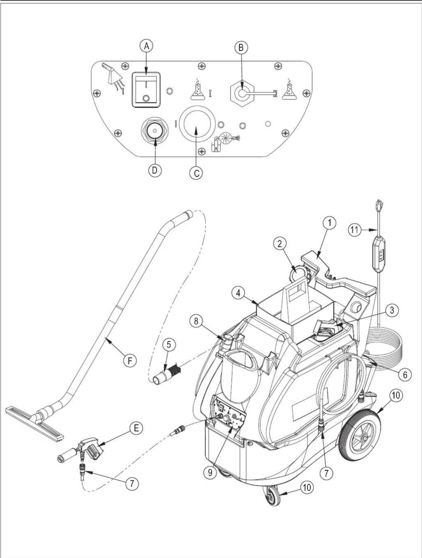
Operator Handle (1): Operator holds onto this handle to move the machine from one location to another.
Solution Tank Lid (2): This lid screws off so the tank can be filled. The solution fill hose is tethered to the lid, and hangs inside the arm of the Operator Handle.
Tools & Accessories (3): Various accessories can be stored on the machine.
Basket (4): This lift-off carrying basket sits on top of the round lid on the Recovery tank.
Recovery Hose (5): Waste water is picked-up through this hose.
Chemical Container Holders (6): Two molded-in bottle holders for chemical jugs.
Spray Hose (7): This hose delivers water from the machine to the cleaning tool.
Drain Hose (8): This hose is used to empty the recovery tank. NOTE: hold the end of the hose above the water level in the tank to avoid sudden, uncontrolled flow of waste water when you remove the cap, then lower the hose slowly to control the rate of discharge.
Switch Plate (9): The machine's on/off switches for the vacuum and for the pump are located here and this is where the valve to change chemical feeds is located.
Castors and Wheels (10): Castors pivot for ease of steering, and large back wheels make it easy to roll the machine from location to location.
Power Cord (11): The 25 ft. power cord connects to a power cord pigtail on the rear of the machine.
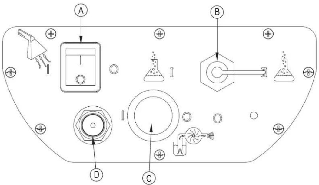
KNOW YOUR SWITCH PLATE
Vacuum Switch (A): turns on the vacuum motor.
Chemical Valve (B): switches between the two chemical containers. When the selector is pointed straight down, the valve is off and neither chemical is selected. When the selector is pointed directly towards one or the other symbols, that chemical is selected.
Solution Pump Switch (C): turns on the solution pump.
Quick Connect (D): this is where solution comes out of the machine and the attachment point for the solution hose.
METERING TIPS
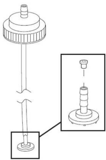
The chemical metering tips allow you to select the ratio of chemical to water, as the water flows out of the machine. Insert the correct metering tip for the desired mixture into the chemical siphon tube.
| METERING TIPS | |||
| COLOR HOLE | SIZE MIX RATIO FLOW RATE | ||
| Orange 0.007 1 oz : | 128 oz 1.0 oz/gal | ||
| Pink 0.012 1 oz : 64 | oz 2.5 oz/gal | ||
| Dark Green 0.014 1 | oz : 50 oz 3.0 oz/gal | ||
| Yellow 0.016 1 oz : | 32 oz 5.0 oz/gal | ||
| Light Blue 0.020 1 oz : | 20 oz 6.0 oz/gal | ||
| Burgundy | 0.022 1 oz : 15 oz 9.0 oz/gal | ||
| Black | 0.048 | 1 oz : 5 oz 20 oz/gal | |
natural_image
Technical line drawing of a mechanical assembly with a cylindrical component and a base, showing no text or symbols.OPERATION
1) Insert the appropriate metering tips into the chemical feed lines (see illustration, page 5).
2) Fill the holding tank with warm water (not exceeding 120 °F). Do not add any chemical to the tank.
3) Prepare the area for cleaning by emptying waste receptacles, clearing debris, removing paper products, blowing out vents, and sweeping floors.
4) Connect the 25 ft power cord (11) to the pig-tail on the rear of the machine. Test the GFCI on the power cord before each use. Plug the GFCI protected power cord into an outlet.
5) PRIME THE PUMP: Attach the priming hose to the outlet quick disconnect (D) and place the open end of the hose into the recovery tank. Turn on the pump and let it run until the pump is completely primed (no visible air in the water stream). Turn the pump off.
NOTE: prime the machine before you place the chemical feed tubes into chemical containers.
6) Disconnect the priming hose and attach the solution hose (7) to the quick disconnect (D).
7) Attach the spray gun to the other end of the solution line.
8) Place chemicals in the molded-in chemical bottle containers (6) on the rear of the machine. Insert one of the feed lines into one of the chemical containers. Secure the line by screwing on the cap. The chemical will feed from which ever container the selector valve (B) on the switch plate is turned towards and when the gun is used in the low pressure setting. Use chemicals with a pH of between 4 and 12. Never add chemicals to the clean water tank.
9) Set the spray gun (E) to low pressure by sliding the pressure selector forward (low pressure = forward; high pressure = back).
10) Turn on the pump switch (C) (push button) and spray through the gun for a few seconds to fill the line with solution.
11) Apply the chemical to the walls and fixtures from the bottom up. Spray the floor last as you work your way out of the room.
12) Allow the chemical to work for the proper amount of dwell time, according to the chemical manufacturer's directions. Agitate heavily soiled areas with a scrub brush.
13) Turn off the chemical injector valve by turning the selector (B) to the down position.
14) Set the spray gun (E) to high pressure and rinse the area from the top down.
15) Connect the recovery hose (5), attach the squeegee (F), and turn on the vacuum (A) (rocker switch).
16) Squeegee off the mirrors, pick up the liquid off the floor with the floor tool. If you have the optional blow dry hose, use it to dry the fixtures.
17) Drain the recovered water into a utility sink or toilet. NOTE: Keep the top of the drain hose (8) higher than the water level in the tank to avoid uncontrolled discharge of water when you open the cap on the hose.

CAUTION
To avoid vacuum motor damage, always use a defoamer any time foam is present.
Before you turn on the vacuum always make sure the filter screen on the ball float is clean and that the ball can travel freely.

RE-PRIMING THE PUMP
If the pump looses prime between jobs, follow the instructions to PRIME THE PUMP, above. If that doesn't get water flowing, put the priming hose into the vacuum inlet hose barb and cover the rest of the space around the priming hose with your hand. Turn on the vacuum (with the pump also running) and let the suction of the vacuum assist in getting water into the pump.
MAINTENANCE
1) Use only approved chemicals at the recommended mix ratios. All chemicals should be added through the feed system and NOT added directly to the water in the solution tank to prevent possible damage to the pump, seals, or other components.
2) For optimum performance, flush the Chemical Feed lines after every job by replacing the chemical containers with containers of clear water and spraying through the gun until the fluid stream is clear. See the Maintenance Schedule, below.
3) The pump seals and/or valves in the high pressure pumps may need to be replaced after about 1000 hours of use, if the pump begins to lose performance or to leak. The pressure regulator valve may need to be when a drop in the spraying pressure at the tool is apparent.
4) If the 4", clear lid is removed from the top of the base (solution tank), you will need to apply a silicone sealant to the threads when you reinstall the lid to seal for vacuum leaks.
MAINTENANCE SCHEDULE
| ITEM DAILY WEEKLY QUARTELY YEARLY | |||
| Flush chemical lines X | |||
| Check/clean vac inlet fi Iter X | |||
| Clean solution fi Iter X | |||
| Check vacuum motor airways X | |||
| Check pump for leaks X | |||
| Check vacuum motor brushes* X |
* Have Clarke check the carbon brushes once a year or after about 500 hours of operation.
TECHNICAL SPECIFICATIONS (as installed and tested on the unit)
| MODEL 56380773 | |
| VACUUM MOTOR: | 2 stage, 8 amp |
| WATER LIFT: | 97" |
| AIR FLOW: | 100 CFM |
| TANK CONSTRUCTION: | Rotationally molded polyethylene |
| SOLUTION TANK CAPACITY: | 20 gallon |
| RECOVERY TANK CAPACITY: | 13 gallon |
| APPLICATION FLOW: | 400 psi |
| VAC & SOLUTION HOSE LENGTH: 25 feet | |
| POWER CORD: | 25 feet |
| HEIGHT: | 38.5 inches |
| WIDTH: | 21.25 inches |
| LENGTH: | 34 inches |
| WEIGHT | 92 LBS |
EL USO INCORRECTO ANULARÁ LA GARANTÍA
CONOZCA SU PLACA DE INTERRUPTORES
PUNTAS DE MEDICIÓN
natural_image
Technical line drawing of a mechanical component with a cylindrical base and flange, shown in two views (no text or symbols)FUNCIONAMIENTO
MANTENIMIENTO
VOTRE PLAQUE DE COMMUTATEURS
EMBOUTS DE DOSAGE
natural_image
Technical line drawing of a mechanical component with two views: top shows a cylindrical part with a flanged end, bottom shows a base with a threaded shaft (no text or symbols)UTILISATION
ENTRETIEN
BASE ASSY
| Item | Ref. | No. | Qty | Description |
| 1 | 5 | 1 | Bolt Hex 1/4-20 X 3/4 Full | |
| 2 | 14 | 9 | Washer Flat 3/16 Zinc Plat | |
| 3 | 170 | 1 | Elect Butt Conn 10-12 Ga Non-I | |
| 4 | 239 | 1 Fitting-Adapter-Brass-3-4x3-8 | ||
| 5 | 325 | 6 Nut-Nylon Lock-Ss-8-32 | ||
| 7 | 983 | 1 | LID And RING 4 LID CLEAR | |
| 8 | 1065 | 1 5' Hose Fill Apc | ||
| 9 | 1097 | 1 Bolt-Hex-1/4-20 X 1/2-Ss | ||
| 10 | 1345 | 1 Washer-Fender-1/4 Id-1 Od-Ss | ||
| 11 | 1460 | 3 Washer Internal Tooth 10 | ||
| 12 | 1602 | 1 Clip Handle Black Vinyl Coated | ||
| 13 | 1603 | 1 Strap/Buckle Cord Wrap W/Spur | ||
| 14 | 1609 | 1 Grommet 3/4 Id X 3/16 Panel | ||
| 15 | 1648 | 1 Cap Garden Hose 3/4 Fght N | ||
| 16 | 2084 | 2 Wheel 10 Grey Plastic Insert | ||
| 17 | 56380594 | 1 Caster-Plate-Orca | ||
| 18 | 56380696 | 1 Foam Reticulated 20 Ppi 1/2 X | ||
| 19 | 56380755 | 2 Plug Square Tube Smooth 3/4 | ||
| 20 | 56380942 | 1 Gasket For Apc Closed Cell B | ||
| 21 | 56510442 | 1 Cap – Extra Vent TSB-FC-2015-031 | ||
| 22 | 1065A | 1 Adapter Faucet Inside/Outsid | ||
| 23 | 1645 | 1 Strap-0.75 x 13.75-Black-Poly Web | ||
| 24 | 27AUSP | 2 Axel Cap Black Pal Nut | ||
| 25 | 325C | 1 Bolt-Php-Ss-8-32x1/2 | ||
| 26 | 382C 6 Screw 8-32 X 7/8 Panhead Phi | |||
| 27 | 5A 8 Screw 1/4-20 X 5/8 Hesx | |||
| 28 | 79B 1 Tie Wire 8 W/Mounting Hole | |||
| 29 | 801F 2 Hinge Pin 1/4 X 2.25 S/S | |||
| 31 | 905USP | 2 Caster Swivel 4 Gray Non Ma | ||
| 32 | 910-2150 | 1 Axel Rod Zinc Plated 1/2 | ||
| 33 | 56380935 | 1 Holding Tank/Base Complete | ||
| [] | 56380921 | 1 Label Kit TFC400 |
[] = Not Shown
* = Optional, Not Included
EQUIPMENT PALLET
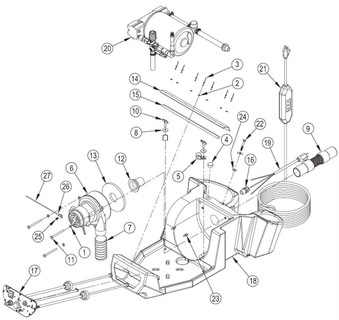
EQUIPMENT PALLET
| Item | Ref. | No. | Qty | Description |
| 1 | 14 | 3 | Washer Flat 3/16 | Zinc Plat |
| 2 | 25 | 7 Washer-Flat-Al-As-8 | ||
| 3 | 75 | 7 | Rivet 1/8 | Dia Aluminum 1/8 T |
| 4 | 183 | 1 | Plug For A .875 | Hole Used On |
| 5 | 231 | 2 | Hose Clamp 3/4 | I.D. For Hhp |
| 6 | 408 | 1 | Vac Motor. | 120v |
| 7 | 561 | 13132 | 1 | Vac Hose Rubber 4.0 X 2.0 ID |
| 8 | 1345 | 3 | Washer 1/4 I.D. 1 O.D. F | |
| 9 | 1136 | 1 | Hose Vacuum Clear 1-1/2 X | |
| 10 | 1548 | 2 | Screw Thumb 1/4-20 X 1 Type | |
| 11 | 1574 | 3 | Bolt 1/4-20 | |
| 12 | 1630 | 1 | Sleeve Vacuum Outlet For Hos | |
| 13 | 2013A | 1 | Gasket 1 Side Adhesive 5 1/2 | |
| 14 | 2197 | 16" | Seal Neoprene 5/8 Gap X 1-1 | |
| 15 | 1043A | 14" | Gasket-Poron-.375 Thick | |
| 16 | 230USP | 1 | Retainer Power Cord Water T | |
| 17 | 1 | Switch Assembly Apc-12 Clarke. NOTE 1 | ||
| 18 | 56380930 | 1 | Equipment Pallet Clarke Orca | |
| 19 | 2155 | 1 | Power Cord Pigtail 12/3 SJTW | |
| 20 | 1 | Pump Assembly For Apc 120v. W/ NOTE 2 | ||
| 21 | 56380774 | 1 | Power Cord/GFCI Assembly For M | |
| 22 | 138A | 1 | Bolt Hex 1/4-20 X 1-3/4 | |
| 23 | 56244138 | 2 | Rec .250 Ins 16 – 14 AWG | |
| [] | 56384140 | 1 | Harness-Orca 1 | |
| 24 | 218 | 1 | Washer Rubber 1/4 Id X 3/4 | |
| 25 | 33 | 1 | Screw 10-32 X 3/8 Slotted | |
| 26 | 65 | 1 | Electrical Connec. Ring 10 St | |
| 27 | 479 | 1 | Wire Green 14 Gauge 500ft |
[] = Not Shown
NOTE 1: See SWITCH PLATE ASSY.
NOTE 2: See PUMP ASSY.
PUMP ASSY
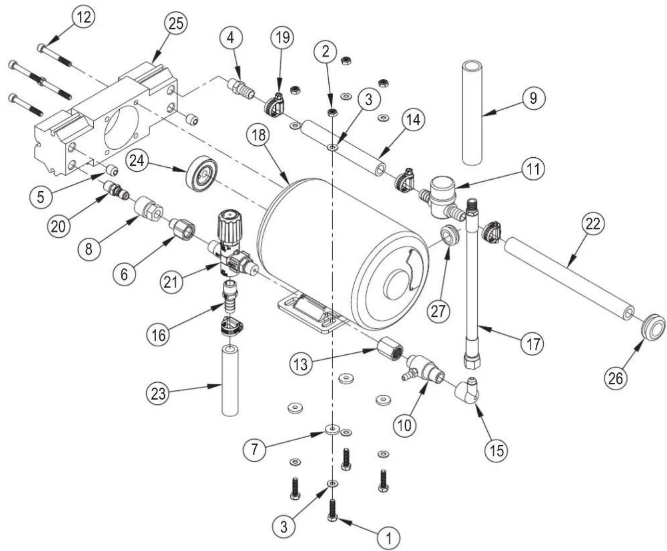
PUMP ASSY
| Item | Ref. | No. | Qty | Description |
| 1 | 4 | 4 | Bolt-Hex-Flthrd-Ss-Zp-1-4-20x1 | |
| 2 | 8 | 4 | Nut-Nylock-Zp-1-4-20 | |
| 3 14 8 Washer Flat 3/16 Zinc Plat | ||||
| 4 165 1 Hose Barb 1/4 Pipe X 1/2 Hose Brass | ||||
| 5 211 2 Plug Brass Pipe 1/4 Pipe H | ||||
| 6 217 1 Reducer 3/8 Pipe Female To 1 | ||||
| 7 | 218 | 4 | Washer-Flat-1/4x3/4x1/8-60 Dur0 | |
| 8 220 1 Qd-Brass-1/4 Fpt-Socket Straight | ||||
| 9 460 | 6" | Tube-Blk-3-4 Id X 1 X 100ft | ||
| 10 | 1049 1 | Injector Chemical Brass 4500 | ||
| 11 | 1050 1 | Filter Water In-Line | ||
| 12 | 1147 | 4 | Screw-Shcs-Ss-1/4-20x2x1 | |
| 13 | 1517 1 | Coupling-3-8 X 3-8-Brass | ||
| 14 | 1550 | 6" | Hose 1/2 Id Wire Reinforced | |
| 15 | 1658 1 | Flare Fitting Fm 90 Deg -6 X | ||
| 16 | 1659 | 1 | Hose Barb 1/2 Hose To 3/8 M | |
| 17 | 1660 | 1 | Hose-21 In-1-4-Mpt-45-Fem-Flare-6 | |
| 18 | 2060 1 | Motor A/C 1/3 Hp For 300 Psi P | ||
| 19 | 166USP | 4 | Hose Clamp-Ss-3/8-7/8 | |
| 20 | 221USP | 1 | Qd-Plug-Brass-1/4 Mpt-St | |
| 21 | 945D 1 | Unloader Valve For 500 Psi Pum | ||
| 22 | 946 | 8.75" | Hose 1/2 Id 2 Braid 200 Psi | |
| 23 | 946 | 4" | Hose 1/2 Id 2 Braid 200 Psi | |
| 24 | 950A 1 | Bearing & Cam Assembly .110 | ||
| 25 | 950F 1 | Pump Piston Style 300-500 Ps | ||
| 26 | 1609 1 | Grommet 3/4 Id X 3/16 Panel | ||
| 27 | 56050955 | 1 | Grommet | |
SWITCH PLATE ASSY
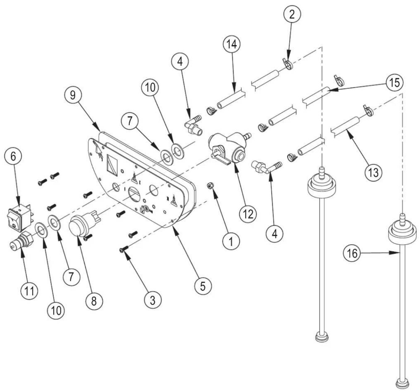
SWITCH PLATE ASSY
| Item | Ref. | No. | Qty | Description |
| 1 | 16 | 1 | Nut Nylon Lock 6/32 Z.P. | |
| 2 | 35 | 6 | Tie 4 Black Weather Resis | |
| 3 | 267 | 8 Screw-Php-Ss-6x1/2-Sms | ||
| 4 | 1000 | 2 | Hose Barb 90 Deg Nylon 1/8 Mpt | |
| 5 | 1628 | 1 Switchplate | ||
| 6 | 1644 | 1 | Switch Rocker Dpst On/Off 20 | |
| 7 | 115USP | 2 Washer 1 Od X 9/16 Id X | ||
| 8 | 1623R | Switch On-Off Illuminated Cle | ||
| 9 | 1628G | 1 | Gasket-Poron-Switchplate | |
| 10 | 31USP | 2 | Washer Brass Half Hard 1 X | |
| 11 | 45USP | 1 | Quick Disconnect Plug Male | |
| 12 | 988B | 1 Valve 3-Way For Spotter & Apc | ||
| 13 | FP277 | 1 Hose 1/4 ID x 61 Chemical | ||
| 14 | FP277 | 1 Hose 1/4 ID x 61 Chemical | ||
| 15 | FP280 | 1 Hose 1/4 x 30 Chem/Bottle | ||
| 16 | 1079 | 2 Chemical Feed Cap & Tube W/Ff |
TANK ASSY
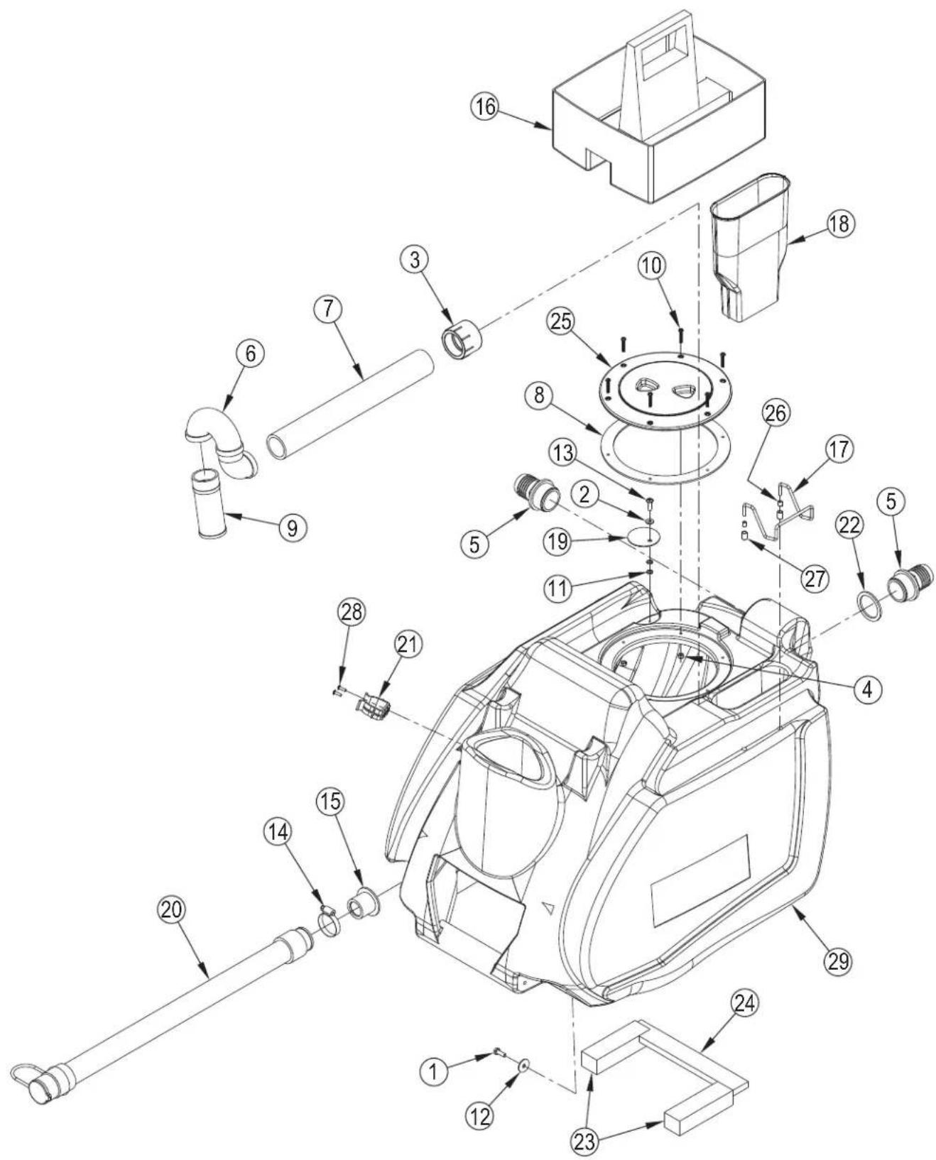
TANK ASSY
| Item | Ref. | No. | Qty | Description |
| 1 | 5 | 1 | Bolt Hex 1/4-20 X 3/4 Full | |
| 2 | 398A | 1 | Washer 1/4 AN S/S Flat .515 | |
| 3 | 1528 | 1 | Adapter Female 1 1/2 | |
| 4 | # | 56002877 | 6 | Nut Hex Nyl Loc Ss 8-32 |
| 5 | 907 | 2 | Hose Barb Fitting Black Abs | |
| 6 | 1154A | 1 | Adapter ABS 1-1/2 P-Trap | |
| 7 | 935 | 14.5 | PVC Pipe 11/2 SCH 40 | |
| 8 | 1129 | 1 | Gasket-Lid-Xlpe-7.15idx.19 Thick | |
| 9 | 929B | 1 | Filter S/S Ball Float | |
| 10 | 1148 | 6 | Screw-Php-Ss-8-32x1 | |
| 11 | 1326 | 2 | Washer 5/16 Flat Cut Nylon | |
| 12# | 87039A | 2 | Washer Fender 1/4 S.S. | |
| 13 | 1445 | 1 | Screw 1/4-20 X 3/4 Round He | |
| 14 | 1518 | 1 | Hose Clamp 3/4 X 1 3/4 Ss | |
| 15# | 1108 | 1 | Spin Weld Boss 1- 3/16 | |
| 16 | 1601 | 1 | Basket Blue 12-1/4 L X 11 | |
| 17 | 1647 | 1 | Hanger-Wire-3/16-Ss | |
| 18 | 1661 | 1 | Sleeve-Wand-.093 Black Abs-94 Hb | |
| 19 | 1662 | 1 | Hose Keeper | |
| 20 | 56381647 | 1 | Drain Hose | |
| 21 | 56407361 | 1 | Clamp. Plastic | |
| 22 | 187B | 1 | Washer-Flat-Buna'n-1-3/4idx0.125 | |
| 23 | 2013B | 2 | Gasket 1.5 X 1.25 X 5.25 A | |
| 24 | 2013C | 1 | Gasket-0.5 X 1.5 X 8.25 | |
| 25# | 56385370 | 1 | Black Lid/9in Ring Assy | |
| 26 | 316AB | 2 | Cap Black .165 I.D. X 27/16 I | |
| 27 | 324AB | 2 | Cap .281 I.D. X 1/2 Long In B | |
| 28# | 56002876 | 2 | Screw 8-32 X 0.5 Pnh Ph Ss | |
| 29# | 56380912 | 1 | Vacuum Tank TFC400 | |
= Revised or new since last update

ACCESSORIES
| Item Ref. No. Qty Description | Item Ref. No. Qty Description |
| TOOLS | OPTIONAL ACCESSORIES |
| 1 61395A 1 Wand Dbl Bend 1/4QC 300 PSI | 12 56209088 1 Squeegee Assembly 24 |
| 2 56108027 1 Wand 2 Piece Alum. Snap Fit | 12 56209089 1 30 Squeegee Assy. |
| 3 56108028 1 Floor Squeegee Tool 14 | 13 56315316 1 Tote Bag |
| 4 56108072 1 Spray Gun Complete | 14 56380871 1 Frame Assembly For Front Moun |
| 5 56381646 1 Hose Vac 5/1 Long Cuffs 1.6X25 | [ ] 56380856 1 Frame Mircofiber Mop Used Wit |
| 6 56380853 1 Handle 12 For Hand Squeegee | [ ] 56380857 1 Mop Microfiber 6 Per Kit |
| 7 56380854 1 Squeegee 12 Inch For Use With | [ ] 56380877 1 Blower Hose And Nozzel Assembl |
| 8 56380938 1 Maids Toteblue | [ ] 56380913 1 Chemical Injector And Metering |
| 9 56380855 1 Brush Dual Surface With Sque | [ ] = Not Shown |
| 10 56380838 1 Pressure Line 25 Ft Complete | |
| 11 SUBSYP1 1 Syphon Hose For HHP-12 | |
| [ ] 56380802 1 Metering Tips Kit Two Each Of | |
| [ ] 56380852 1 Handle 54 Black Metal For |
WIRING DIAGRAM BEFORE JUNE 2015
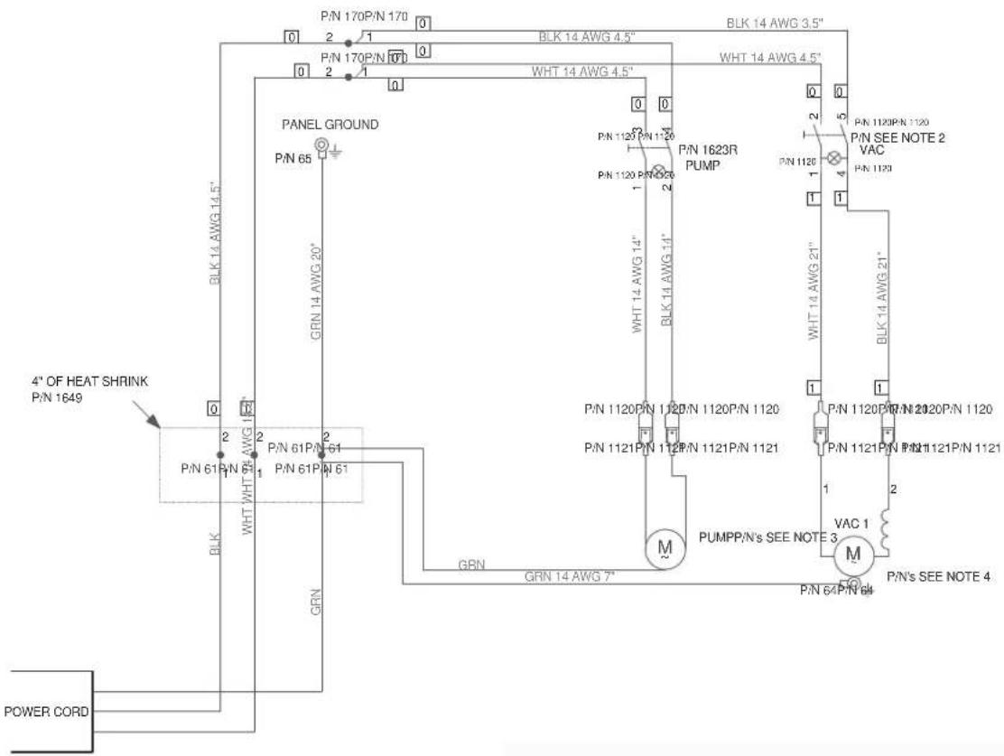
- NON-CSA MACHINE
- VAC SWITCH
ALL CLEANER - P/N 2123
ALL CLEANER XP AND TFC 400 - P/N 1644 - PUMPS
ALL CLEANER - P/N 960
ALL CLEANER AND TFC 400 - P/N 2060(120V)
APC 328(400PSI) - P/N 2064-CE - VAC
ALL CLEANER - P/N 408
ALL CLEANER XP AND TEC 400 - P/N 408
APC 328/400PSU - P/N 407A
ALL CLEANER XP AND TFC 400 - P/N 2060(120V)
WIRING DIAGRAM AFTER MAY 2015
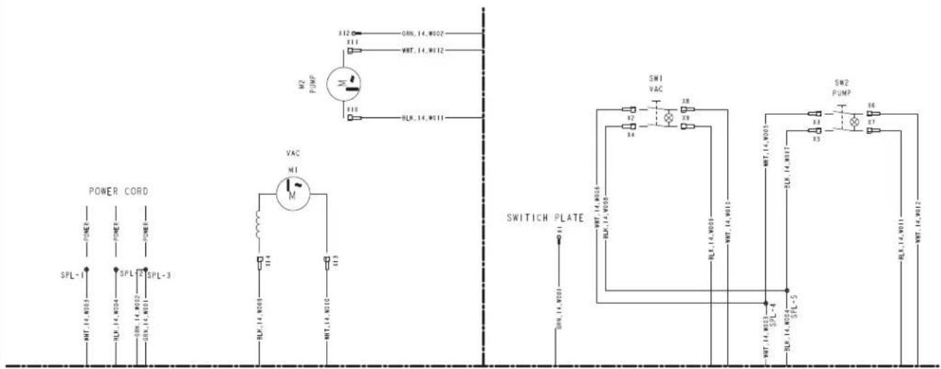
Clarke®
9435 Winnetka Ave North
Minneapolis, MN 55445
www.clarkeus.com
Phone: 800-253-0367
Fax: 800-825-2753
©2018 Nilfi sk, Inc.



- IMPORTANT SAFETY INSTRUCTIONS
- WARNING!
- SAVE THESE INSTRUCTIONS
- INTRODUCTION
- PARTS AND SERVICE
- MODIFICATIONS
- NAME PLATE
- UNPACKING
- DO NOT OPERATE THE MACHINE UNTIL YOU HAVE READ THIS SECTION
- IMPROPER USE WILL VOID THE WARRANTY
- 120VAC GROUNDING INSTRUCTIONS
- DANGER!
- KNOW YOUR MACHINE DESCRIPTIONS
- KNOW YOUR SWITCH PLATE
- METERING TIPS
- OPERATION
- CAUTION
- RE-PRIMING THE PUMP
- MAINTENANCE
- EL USO INCORRECTO ANULARÁ LA GARANTÍA
- CONOZCA SU PLACA DE INTERRUPTORES
- PUNTAS DE MEDICIÓN
- FUNCIONAMIENTO
- MANTENIMIENTO
- VOTRE PLAQUE DE COMMUTATEURS
- EMBOUTS DE DOSAGE
- UTILISATION
- ENTRETIEN
- = Revised or new since last update
- Clarke®
Brand : Clarke
Model : TFC 400
Category : Pressure washer