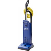
CarpetMaster 212 - Vacuum Cleaner Clarke - Free user manual and instructions
Find the device manual for free CarpetMaster 212 Clarke in PDF.



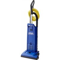
| Product type | Professional canister vacuum |
| Brand | Clarke |
| Model | CarpetMaster 212 |
| Rated power | 1200 W |
| Voltage / Frequency | 120 V / 50-60 Hz |
| Weight | 7.7 kg |
| Sound pressure level | 69 dB(A) |
| Electrical protection class | I (grounded) |
| Brush type | Motorized brush (DMU models) height adjustable |
| Filtration | HEPA filter (optional) + pre-filter + exhaust filter |
| Bag capacity | Paper or cloth dust bag (not specified, estimated 5 liters) |
| Full bag indicator | Yes, indicator light |
| Cord length | Not specified (estimated 12 m) |
| Included accessories | Wand, crevice tool, round brush |
| Usage | Indoor, dry surfaces only |
| Maintenance | Regular bag replacement, filter cleaning, brush replacement |
| Safety | Grounding required, brush motor overload protection (DMU models) |
Frequently Asked Questions - CarpetMaster 212 Clarke
User questions about CarpetMaster 212 Clarke
0 question about this device. Answer the ones you know or ask your own.
Ask a new question about this device
Download the instructions for your Vacuum Cleaner in PDF format for free! Find your manual CarpetMaster 212 - Clarke and take your electronic device back in hand. On this page are published all the documents necessary for the use of your device. CarpetMaster 212 by Clarke.
USER MANUAL CarpetMaster 212 Clarke
natural_image
3D rendering of a vacuum cleaner with handle and control panel (no visible text or symbols)INSTRUCTIONS FOR USE MODE D'EMPLOI
INSTRUCCIONES DE USO

READ THIS BOOK
LEA ESTE LIBRO
LISEZ CE MANUEL

This book has important information for the use and safe operation of this machine. Failure to read this book prior to operating or attempting any service or maintenance procedure to your Clarke machine could result in injury to you or to other personnel; damage to the machine or to other property could occur as well. You must have training in the operation of this machine before using it. If your operator(s) cannot read this manual, have it explained fully before attempting to operate this machine.
For new books write to: Clarke®, 2100 Highway 265, Springdale, Arkansas 72764.
CarpetMaster®
natural_image
Exploded view diagram of a household appliance assembly, showing internal components like hand tools, refrigerators, and washing machines (no text or labels)CarpetMaster®
English 4-13
Français 14-23
Español 24-33
Clarke reserves the right to make changes or improvements to its machine without notice.
Always use genuine Clarke Parts for repair.
Clarke®
2100 Highway 265
Springdale, Arkansas, 72764
CONTENTS
Important Safety Instructions 5
Grounding Instructions 6
Introduction 7
Parts and Service 7
Rating plate 7
Unpacking the Machine 7
Technical Specifications....7
Know Your Machine 8
Set-Up and Assembly 8
Operating the Machine 9
Using the Wand.... 10
Using the Tools....10
Maintenance.... 11
Changing the Paper Dust Bag.... 11
Changing the Cloth Dust Bag.... 11
Changing the Brush 12
Changing the HEPA-fi Iter....12
Changing the Exhaust fi Iter....13
Cleaning or changing the Pre-Filter 13
After Using the Machine 13
IMPORTANT SAFETY INSTRUCTIONS
When using an electrical appliance, basic precautions should always be followed, including the following:
Read all instructions before using this appliance.
This machine is for commercial use, for example in hotels, schools, hospitals, factories, shops and offices other than normal residential housekeeping purposes.
THIS APPLIANCE IS INTENDED FOR DRY USE ONLY!
DO NOT USE FOR WET FLOOR OR CARPET!
WARNING!
To reduce the risk of fi re, electric shock, or injury:
* Do not leave the appliance when it is plugged in. Unplug the unit from the outlet when not in use and before servicing.
WARNING!
To reduce the risk of electric shock, do not use outdoors or on wet surfaces.
* Do not allow to be used as a toy. Close attention is necessary when used by or near children.
* Use only as described in this manual. Use only the manufacturer's recommended attachments.
* If the appliance is not working as it should be, has been dropped, damaged, left outdoors or dropped into water, return it to a service center. The machine must not be used if the electrical cord shows any sign of damage.
Regularly inspect the cord for damage, particularly if it has been crushed, shut in a door or run over.
* Do not pull or carry by the cord, use the cord as a handle, or pull the cord around sharp edges or corners. Keep the cord away from heated surfaces.
* Do not unplug by pulling on the cord. To unplug, grasp the plug, not the cord.
* Do not handle the plug, cord or appliance with wet hands.
* Do not put any object into openings. Do not use with any opening blocked.
* Keep loose clothing, hair, fingers, and all parts of body away from openings and moving parts.
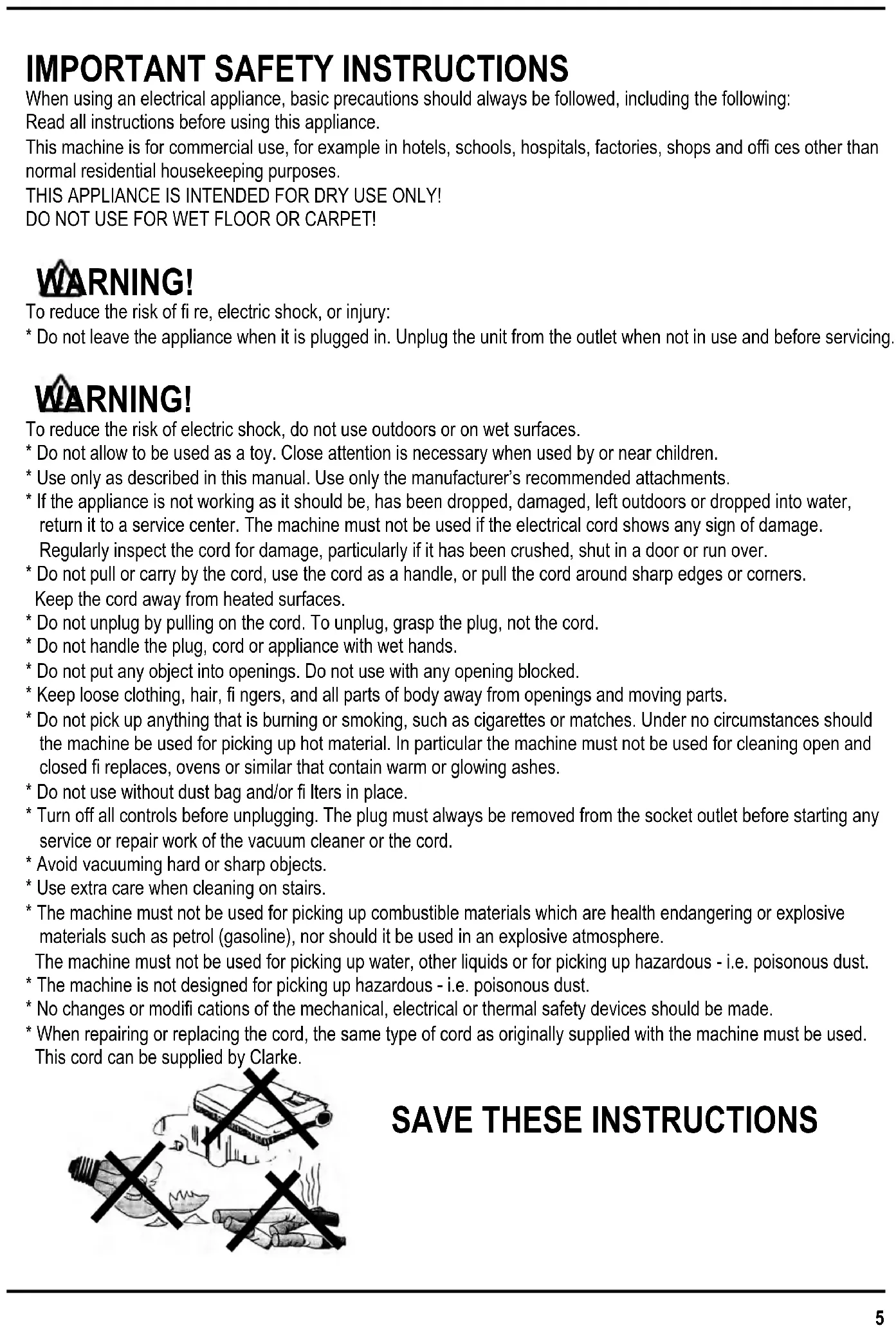
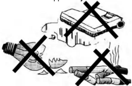
* Do not pick up anything that is burning or smoking, such as cigarettes or matches. Under no circumstances should the machine be used for picking up hot material. In particular the machine must not be used for cleaning open and closed fi replaces, ovens or similar that contain warm or glowing ashes.
* Do not use without dust bag and/or filter in place.
* Turn off all controls before unplugging. The plug must always be removed from the socket outlet before starting any service or repair work of the vacuum cleaner or the cord.
* Avoid vacuuming hard or sharp objects.
* Use extra care when cleaning on stairs.
* The machine must not be used for picking up combustible materials which are health endangering or explosive materials such as petrol (gasoline), nor should it be used in an explosive atmosphere.
The machine must not be used for picking up water, other liquids or for picking up hazardous - i.e. poisonous dust.
* The machine is not designed for picking up hazardous - i.e. poisonous dust.
* No changes or modifications of the mechanical, electrical or thermal safety devices should be made.
* When repairing or replacing the cord, the same type of cord as originally supplied with the machine must be used.
This cord can be supplied by Clarke.
SAVE THESE INSTRUCTIONS
GROUNDING INSTRUCTIONS
This appliance must be grounded. If it should electrically malfunction, grounding provides a path of least resistance for electric current to reduce the risk of electric shock. This appliance is equipped with a cord having an equipment-grounding conductor and grounding plug. The plug must be plugged into an appropriate outlet that is properly installed and grounded in accordance with all local codes and ordinances.

GER!
Improper connection of the equipment-grounding conductor can result in a risk of electric shock. Check with a qualified electrician or service person if you are in doubt as to whether the outlet is properly grounded. Do not modify the plug provided with the appliance.
If it will not fit the outlet, have a proper outlet installed by a qualified electrician.
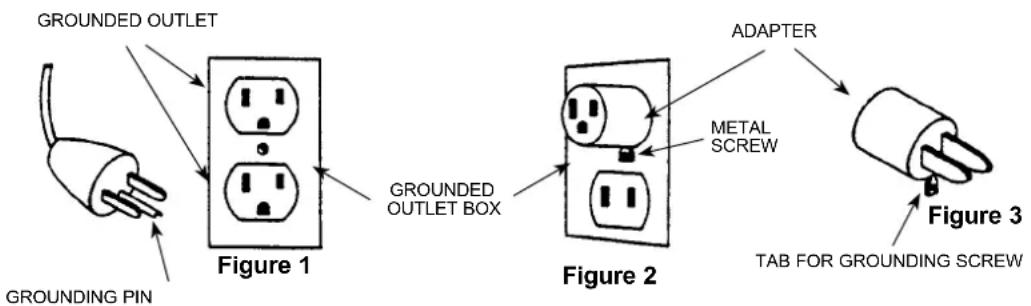
This appliance is for use on a nominal 120-volt circuit, and has a grounding plug that looks like the plug illustrated in Figure 1 below. A temporary adapter illustrated in Figures 2 and 3 may be used to connect this plug to a 2-pole receptacle as shown in Figure 2 if a properly grounded outlet is not available. The temporary adapter should be used only until a properly grounded outlet (Figure 1) can be installed by a qualified electrician.
The green-colored rigid ear, tab, or the like extending from the adapter must be connected to a permanent ground such as a properly grounded outlet box cover. Whenever the adapter is used, it must be held in place by a metal screw. Grounding adapters are not approved for use in Canada.
Replace the plug if the grounding pin is damaged or broken.
The Green (or Green/Yellow) wire in the cord is the grounding wire. When replacing a plug, this wire must be attached to the grounding pin only.
Extension cords connected to this machine should be 12 gauge, three-wire cords with three-prong plugs and outlets. DO NOT use extension cords more than 50 feet (15 meter) long.
PLEASE NOTE: FOR NORTH AMERICA ONLY
flowchart
graph LR
    A["Grounding Pin"] --> B["Figure 1"]
    B --> C["Grounded Outlet Box"]
    C --> D["Figure 2"]
    D --> E["ADAPTER"]
    E --> F["Figure 3"]
    F --> G["TAB FOR GROUNDING SCREW"]
    style A fill:#f9f,stroke:#333
    style B fill:#ccf,stroke:#333
    style C fill:#cfc,stroke:#333
    style D fill:#fcc,stroke:#333
    style E fill:#cff,stroke:#333
    style F fill:#ffc,stroke:#333
INTRODUCTION
This manual will help you get the most from your Clarke Carpetmaster vacuum cleaner.
Read it thoroughly before operating the machine. This product is intended for commercial use only.
PARTS AND SERVICE
Repairs, when required, should be performed by your Authorized Clarke Service Center, who employs factory trained service personnel, and maintains an inventory of Clarke original replacement parts and accessories.
Call the Clarke DEALER named below for repair parts or service.
Please specify the Model and Serial Number when discussing your machine.
(Dealer, affi x service sticker here.)
RATING PLATE
The Model Number and Serial Number of your machine are shown on the rating plate on the machine. This information is needed when ordering repair parts for the machine. Use the space below to note the Model Number and Serial Number of your machine for future reference.
MODEL NUMBER
SERIAL NUMBER ____
UNPACKING THE MACHINE
When the machine is delivered, carefully inspect the shipping carton and the machine for damage.
If damage is evident, save the shipping carton so that it can be inspected.
Contact the Clarke Customer Service Department immediately to file a freight damage claim.
Visit our web page; www.clarkeus.com
TECHNICAL SPECIFICATION
(as installed and tested on the unit)
| Model Single motor | 112, 115GU 12 SMU,GU 15 SMU | Double motor212, 215, 218GU 12 DMU,GU 15 DMUGU 18 DMU | |
| Voltage V/Hz 110-120/50-60 110-120/50-60 | |||
| Rated Power W 1000 1200 | |||
| Protection class (electrical) | | ± | | ± | |
| Sound Pressure Level dB(A) 69 69 | |||
| Total weight lbs/Kg 17/7.7 | 18.7/8.5 |
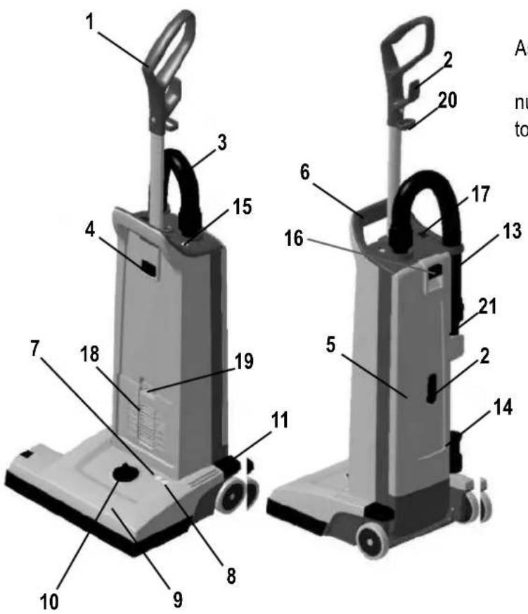
KNOW YOUR MACHINE
As you read this manual, you will occasionally run across a bold number in parentheses - example: (2). These numbers refer to an item shown on this page. Refer back to this page whenever necessary, to pinpoint the location of an item mentioned in the text.
1 Handle
2 Cord Hook
3 Vacuum Hose
4 Handle Lock Button
5 Dust lid
6 Carrying Handle
7 Light, Green - Only Double Motor Unit (212, 215, 218 - versions)
8 Light, Red Only Double Motor Unit (212, 215, 218 - versions)
9 Brush Housing
10 Brush Height Adjustment Knob
11 Pedal
13 Wand
14 Crevice Tool
15 "Dust Bag Full" Indicator
16 Dust lid button
17 Main Power Switch
18 Exhaust Filter Cover
19 Filter Cover Latch
20 Power Cord Clamp
21 Dusting Brush
natural_image
Person using a vacuum cleaner to lift a hose, no visible text or symbols2
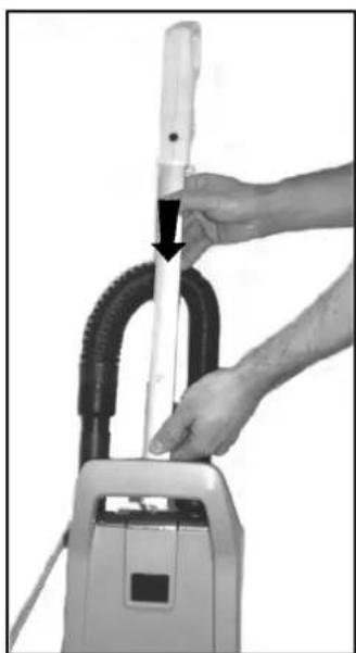
Insert the handle at the opening at the top of the bag housing, until the button at handle snaps in place.
SET UP AND ASSEMBLY
- Carefully take out the vacuum cleaner from its carton.
- Push the Handle (1) into the opening at the top of the Dust compartment until the button at the rod snaps in place and secure the handle to the housing.
Never operate the vacuum cleaner without a Dust Bag in place. Thease machines is equipped with an "no bag" clip. This means that if a dust bag not is fi tted or fi tted uncorrect - the dust lid (5) would not be able to close.
IMPORTANT!
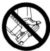
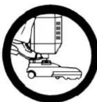
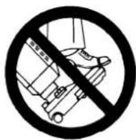
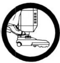
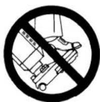
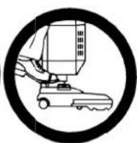
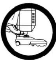
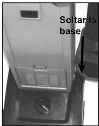
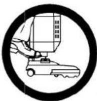
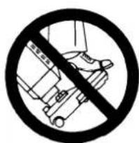
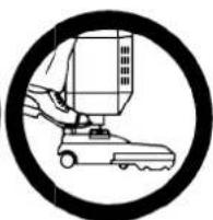
Foot pedal must be used to release base to operating/non operation position. Failure to do so could result in damage to the release mechanism.
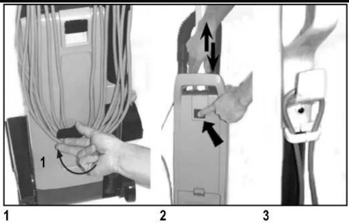
- Release the power cord from the cord hooks (2) at the backside of the vacuum cleaner. Turn the lower hook so that the cord is released. Unwind the whole power cord.
- Adjust the height of the handle, by pushing at the handle lock button (4) and then pull or push at handle to make it comfortable to use.
- Add the cord to the hook of the handle in order to make an anti strain function. Then plug-in the power cord into a electrical outlet.
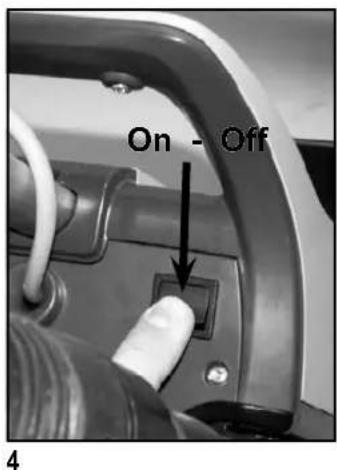
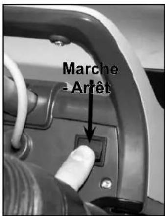
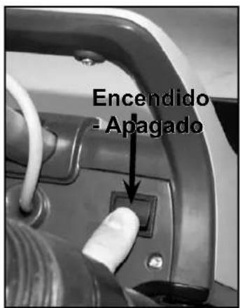
- Turn the Main Power Switch (17) ON. "I" is ON and "O" is OFF. Now the vacuum motor will start.
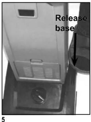
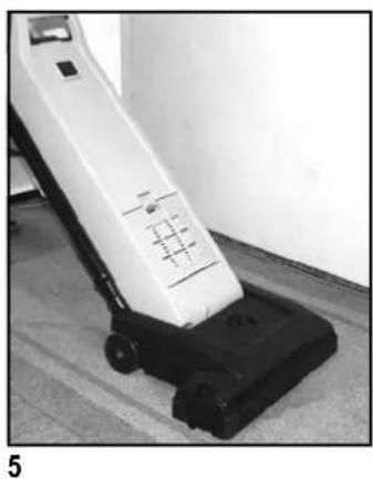
- Step on the Pedal (11) and then tilt the cleaner backwards. Now the brush motor will start (Dual-versions only). At Dual-versions the green light (7) at the brush housing (9) will come on to indicate that the brush motor is running.
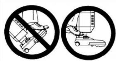
IMPORTANT!
Foot pedal must be used to release base to
operating/non operation position. Failure to do so could result in damage to the handle release mechanism.
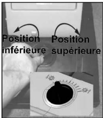
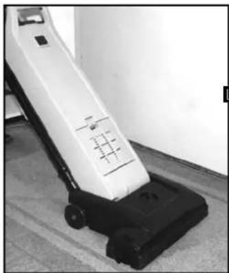
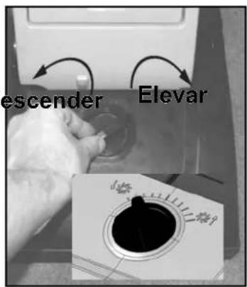
- Turn the Height Adjustment Knob (10) to adjust the height that the brush will operate in - depending on the material at the surface to be vacuumed. For carpets with short textiles the brush should in the lower position. Turn the knob to the left (when you are placed in front of the machine) to lower the brush. For carpets with longer textiles the brush should in a higher position. Turn the knob to the right (when you are placed in front of the machine) to set the brush at a higher level. If the red light comes on, slowly turn the knob in the opposite direction until the light goes off.
If the red light (8) stays on continuously, there may be debris wrapped around the brush, during operation. At a double motor units this can cause the overload protector for the brush motor to trip. If this occurs, turn the Main Switch (17) OFF and unplug the power cord. Remove any debris from the brush and plug in the power cord, turn the Main Switch (17) back ON. This will automatically reset the overload protector. If the overload protector trips repeatedly contact your dealer for service. For more information of the light indicators at the Dual-versions - see the table below.
NOTE! Always disconnect the power cord before performing any machine maintenance.
Change the bag whenever the "Bag Full" Light (15) comes on. For details of dust bag replacement see separate instruction in this manual. If the light comes on before the bag is full, the inside of the bag may be coated with very fine dust (change the bag), or debris may be built up somewhere between the brush and the bag.
natural_image
Black and white photo of a vacuum cleaner on a tiled floor, no visible text or symbols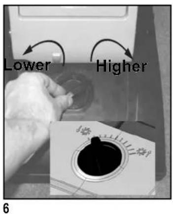
LIGHT INDICATION AND FUNCTION FOR THE BRUSH MOTOR - 212, 215, 218 - Double Motor Units only!
| GREEN RED CONDITION FUNCTION | ||||
| 1. | ON OFF | Normal operation In normal | operation, the green light is constantly illuminated. | |
| 2. | OFF ON - | BLINKING | Brush position too low (heavy loading)  | 1. If the condition 3, red light blinking, continues for 10 seconds or more, the control module will cut out the power supply to the brush motor.2. The red light will still be illuminated until you turn off the switch or unplug the cord. |
| 3. | OFF ON Brush stalled | 1. The red light will be constantly illuminated and the control module will instantly cut the power supply to the brush motor, if the brush was stalled accidentally.2. The red light will still be illuminated until you turn off the switch or unplug the cord. | ||
natural_image
Close-up of hands operating a mechanical device with a textured circular component and a black arrow pointing to the handle (no visible text or symbols)1
natural_image
Person using a leg bench on a wooden floor, no visible text or symbols2
USING THE WAND (OPTIONAL)
The Wand (13) is not supplied as a standard item in all variants of these machines. Do like this in order to use the wand.
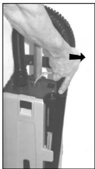
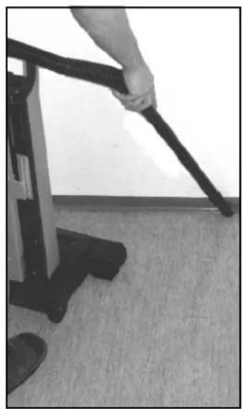
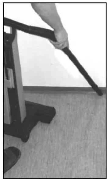
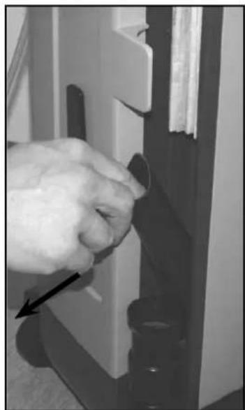
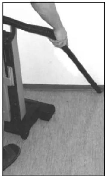
- Push the machine to upright locked position. The brush motor will then stop (Dual-version only), and the brush will be lifted up from the surface at other versions. Then slide the Wand out of its holder.
- Use the wand for cleaning hard to reach places like floor corners, or furnitures.
natural_image
Simple line drawing of a robotic arm inside a circular frame (no text or symbols)IMPORTANT!
Foot pedal must be used to release base to operating/non operation position. Failure to do so could result in damage to the handle release mechanism.
natural_image
Close-up of a hand inserting a black plastic component into a mechanical device (no visible text or symbols)1
natural_image
Close-up of a hand inserting a small component into a device panel (no visible text or symbols)2
USING THE TOOLS (OPTIONAL)
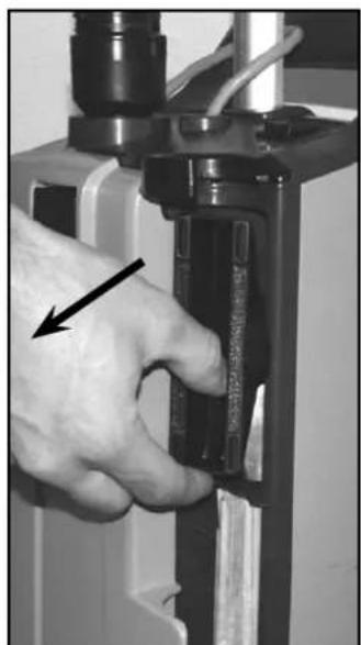
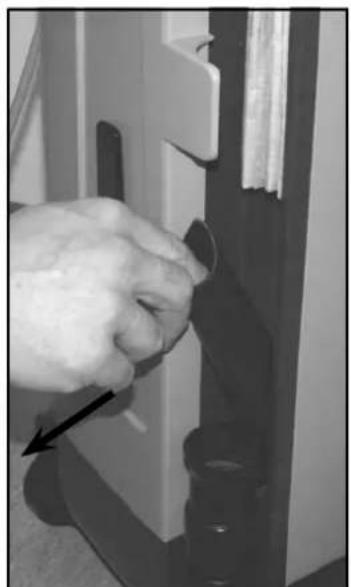
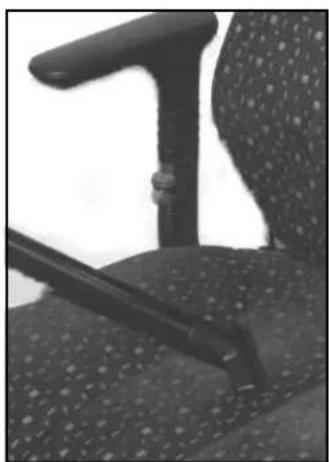
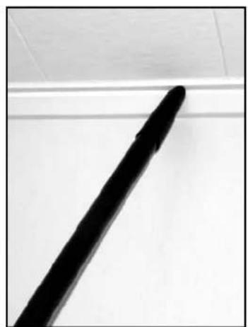
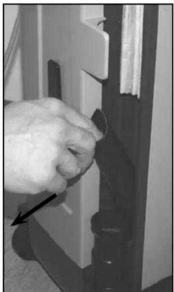
These tools are not standard items in all machine variants. Use these tools for a better cleaning performance at hard to reach areas. A Crevice Tool (14) and Dusting Brush (21) is placed comfortable at the machine, just behind the wand.
Remove the wand from the vacuum cleaner and you will have free access to the Tools.
- The dusting brush is placed in the upper section of the cleaner.
- The crevice tool is placed in the lower section of the cleaner.
natural_image
Close-up of a person's office chair with a black handle and patterned seat (no visible text or symbols)3
natural_image
Close-up of a black cylindrical object on a white surface, no visible text or symbols3
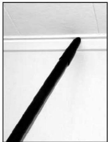
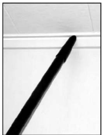
- Install the Crevice Tool or Dusting Brush on the end of the Wand, if desired. Now the vacuum cleaner will have an extended coverage performance and can be used for cleaning hard to reach areas like roof strips, or furnitures.
natural_image
Simple line drawing of a robotic arm inside a circular frame (no text or symbols)IMPORTANT!
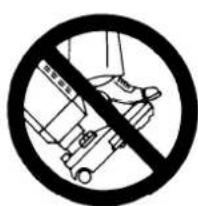
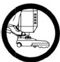
Foot pedal must be used to release base to operating/non operation position. Failure to do so could result in damage to the handle release mechanism.
MAINTENANCE

Always disconnect the power cord before performing any machine maintenance.
| CHANGING THE PAPER DUST BAG | |
| Change the bag whenever the “Bag Full” (15) indicator comes on. To replace the Paper Dust Bag: | |
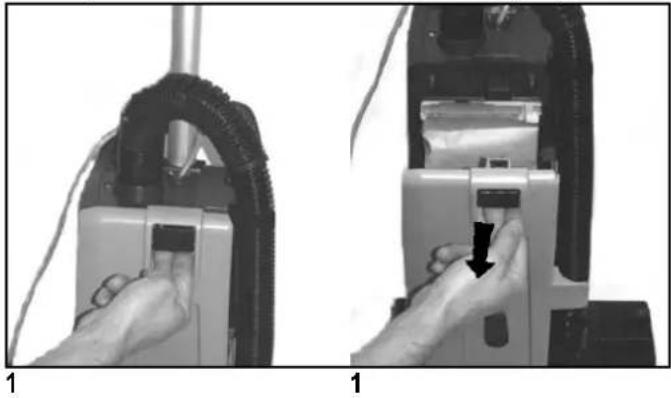
| 1. | Disconnect the power cord from the electrical outlet. Pull the Dust lid button (16) and remove the Dust lid outwards to remove it from the cleaner. |
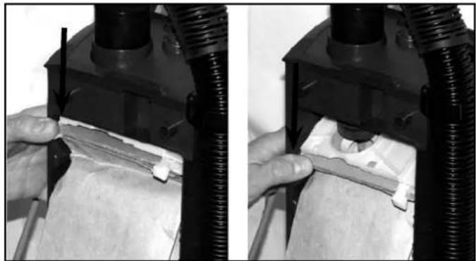
| 2. | Push downwards at the edge to the left of the plastic holder, so that the bag inlet loosens from the vacuum inlet of the machine. |
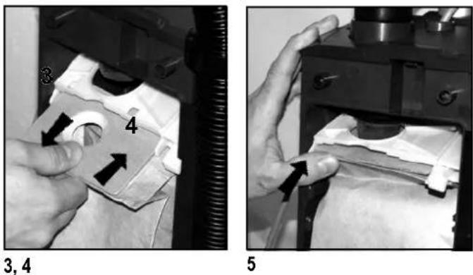
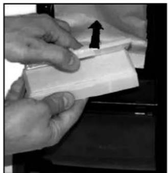
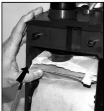
| 3. | Grasp at the cardboard piece of the bag and gently pull the full bag outwards - away from cleaner. |
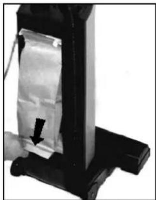
| 4. | Insert a new paper dust bag into the slot of the bag holder and push the bag in place. Check so that the paper dust bag not is jammed in the holder. Only the cardboard piece of the bag should be attached to the bag holder. |
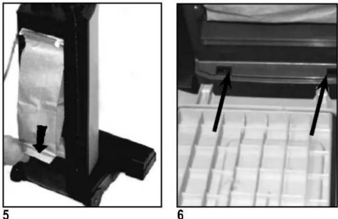
| 5. | Push the bag holder with the new bag upwards, so that the bag inlet fasten to the inlet of the machine. Make sure that the bag is unfold and will fit in place at the bag housing. Also check that the "no bag" clip is placed to the left so that the lid will be able to close. |
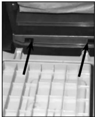
| 6. | Fit the two notches of the back cover to the two slots at the lower part of the bag housing, and push the back cover back in place at the housing. |
NOTE!
Photos below shows changing of the paper dust bag! Never operate the machine without a Dust Bag in place.
natural_image
Two-step diagram showing hand operating a vacuum cleaner device, with no visible text or symbols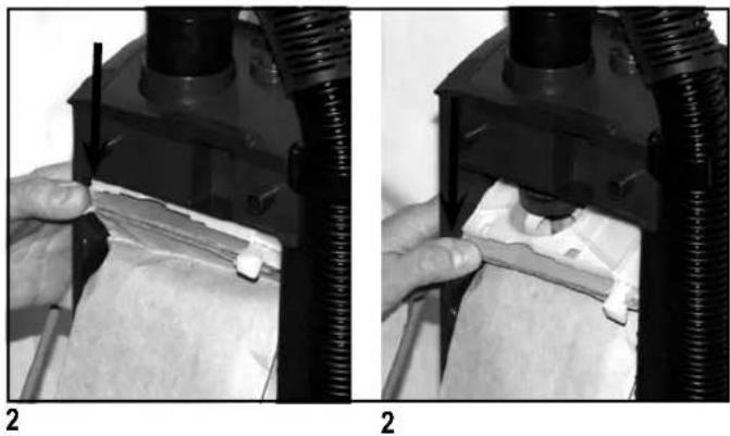
natural_image
Two-panel black-and-white photo showing a hand operating a mechanical device with a tool, no visible text or symbols.| EMPTYING THE CLOTH DUST BAG | |
| Empty the Bag whenever the “Bag Full” Light (15) comes on. To empty or to replace: | |
| 1. | Disconnect the power cord from the electrical outlet. Pull the Dust lid button (16) and drag the Dust lid outwards to remove it from the cleaner. |
| 2. | Push downwards at the edge to the left of the plastic holder, so that the bag inlet loosens from the vacuum inlet of the machine. |
| 3. | Grasp at the plastic fl ange of the bag and gently pull the bag outwards - away from cleaner. |
| 4. | Remove bag clip and shake out bag contents. |
| 5. | Put the bag clip back on the bag. |
| 6. | Insert the cleaned/new cloth bag into the slot of the bag holder and push the bag in place so that bag is secured. |
| 7. | Push the bag holder with the new bag upwards, so that the bag inlet fasten to the inlet of the machine. Make sure that the bag is unfold and will fi t in place at the bag housing. Also check that the "no bag" clip is placed to the left so that the lid will be able to close. |
| 8. | Fit the two notches of the back cover to the two slots at the lower part of the bag housing, and push the back cover back in place at the housing. |
natural_image
Two-panel image showing a printer's internal structure and its assembly with arrows indicating parts of the printer's interior (no text or symbols present)CHANGING OR CLEANING OF THE BRUSH
natural_image
Close-up of a hand holding a black mechanical component with an arrow pointing to it (no visible text or symbols)2
natural_image
Close-up of a hand pressing down on a dark mechanical component with a black arrow indicating the force (no text or symbols visible)3
natural_image
Close-up of a hand pressing down on a coiled metal component (no visible text or symbols)4
natural_image
Close-up of a hand holding a black object with a black arrow pointing to it (no visible text or symbols)6
natural_image
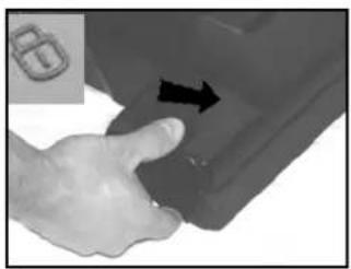
Close-up of a hand pressing down on a car door panel with an arrow indicating left motion (no text or symbols visible)7
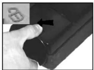
| 1. | Unplug the power cord from the electrical outlet. |
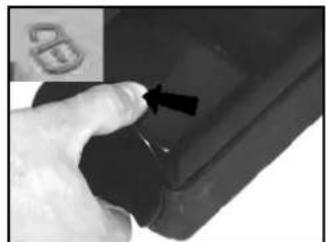
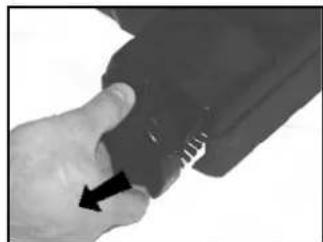
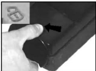
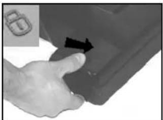
| 2. | Release the brush roller by unlocking the bearing block. Push the button backwards left towards the unlocking symbol at the brush housing. |
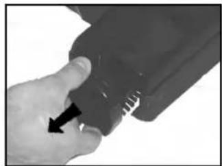
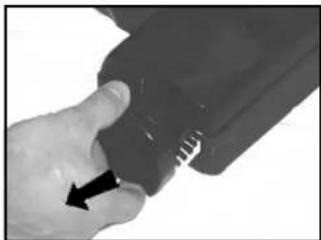
| 3. | Grasp at the bearing block and pull it out from the brush housing. |
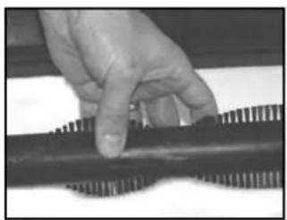
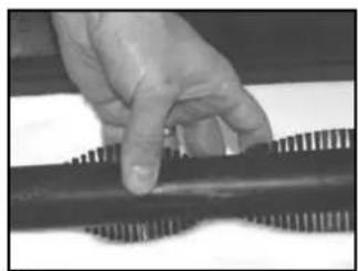
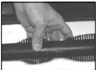
| 4. | Remove the used brush. |
| 5. | Replace the used brush roller with a new one, or clean and remove all debris at the present brush. |
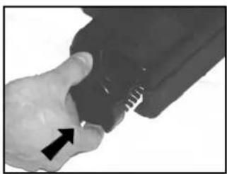
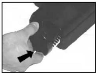
| 6. | Slide back the brush into the the fixed bearing block in the brush house. |
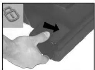
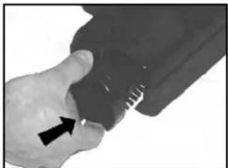
| 7. | Push the bearing block in its position. Lock it by turning clockwise. |

Always disconnect the power cord before performing any machine maintenance.
FILTERS - type of fi Iter may vary from different models
At these machines there are two different fi Iters; one pre-fi Iter before the vacuum motor and one exhaust fi Iter.
There are two different types of exhaust filters available to these machines, HEPA-filter and a standard exhaust filter. The HEPA-filter (High Efficiency Particulate Air filter) offers better filtration capacity then the standard exhaust filter. The exhaust filters catches any dirt that may escape from the dust bag, or motor pre filter. Replace the filter every fourth time that the dust bag is changed (more often in very dusty applications). The exhaust filters is located at the front side of the machine just above the brush house.
The HEPA filter can not be cleaned or washed clean. When the HEPA-fi iter is clogged it must be replaced.
CHANGING THE HEPA-FILTER
natural_image
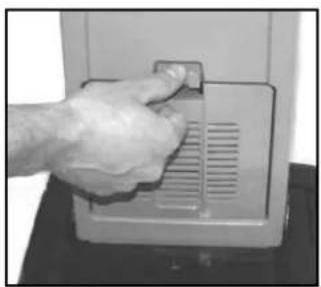
Hand pressing a button on a computer monitor (no visible text or symbols)1
natural_image
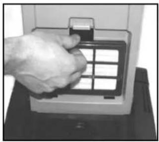
Hand inserting a grid into a device (no visible text or symbols)2
natural_image
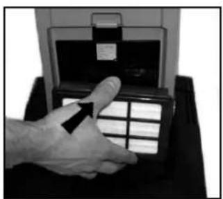
Hand pressing a button on a device (no visible text or symbols)3
natural_image
Close-up of a hand pressing down on a wall-mounted device (no visible text or symbols)4
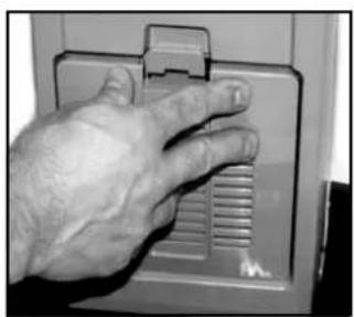
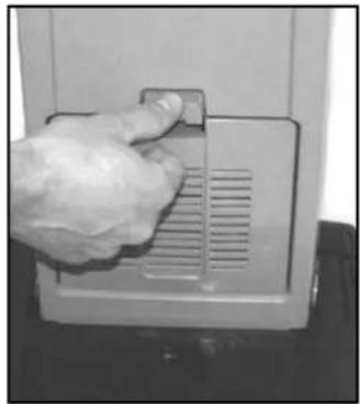
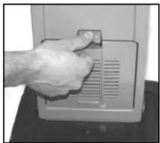
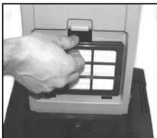
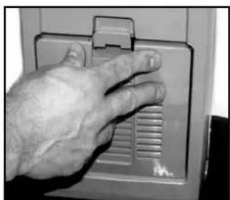
- Disconnect the power cord from the electrical outlet. Push the Filter Cover Latch (19) downwards so that the cover (18) is released. Remove the filter cover from cleaner.
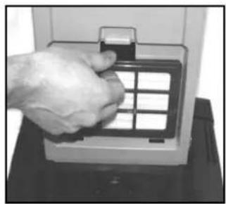
- Grasp at the fi Iter frame and remove the used and dirty HEPA-fi Iter
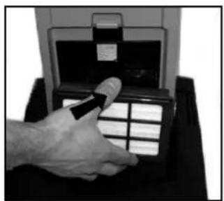
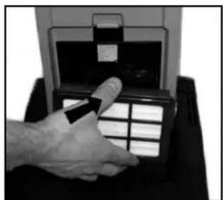
- Grasp at the fi Iter frame and then insert the new HEPA fi Iter to the cleaner by pushing it in place. (Do never touch the fi Iter media at a HEPA-fi Iter! Doing so may cause a loss of performance of the HEPA-fi Iter).
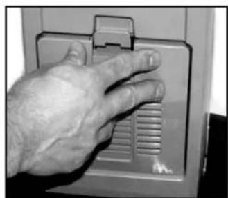
- Snap the Filter Cover back in place at the cleaner.
IMPORTANT!
Never operate the cleaner without the HEPA-Filter in place at the machine. Note! These machines are not designed for picking up hazardous - i.e. poisonous dust!
CHANGING THE EXHAUST FILTER
- Disconnect the power cord from the electrical outlet. Push the Filter Cover Latch (19) downwards so that the Filter Cover (18) is released.
- Remove the cover with the filter, from the cleaner.
- Remove the used and dirty exhaust filter.
- Insert a new exhaust filter to the filter cover.
- Snap the Filter Cover back in place at the cleaner.
IMPORTANT!
Never operate the machine without the Exhaust Filter in place at the machine.
natural_image
Hand placing a small object into a device panel (no visible text or symbols)1
natural_image
Hand inserting a small electronic device into a device casing (no visible text or symbols)2
CLEANING OR CHANGING THE PRE FILTER
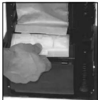
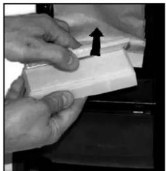
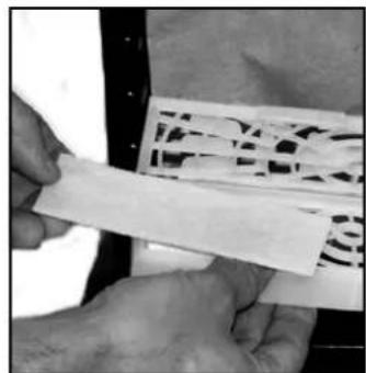
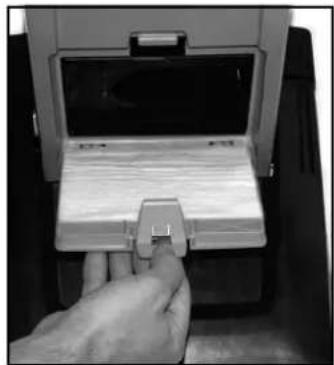
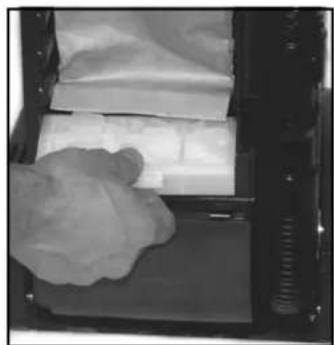
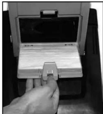
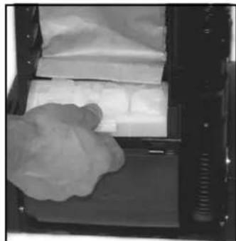
The pre fi liter catches any dirt spilled from the bag, before it can enter the vacuum motor. The fi liter is located below the bag. Clean the fi liter every third time that the bag is changed (more often in very dusty applications).
To clean/replace the Pre Filter.
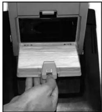
- Disconnect the power cord from the electrical outlet. Then push the Dust lid button (16) in and remove the dust lid (5).
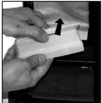
- Grasp at the filter holder and pull the holder out from the Dust compartment.
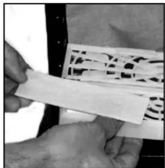
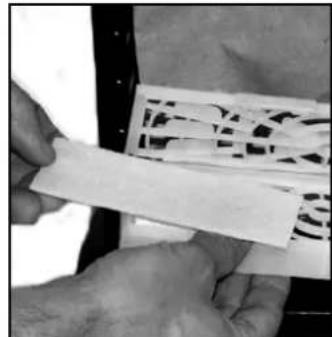
- Remove the dirty fi liter and replace with a new pre fi liter. The pre fi liter may also be washed. Wash it in warm water. Let the fi liter dry completely before putting it back into the fi liter holder.
- This machine is also equipped with a deodorizer function (an anti-smell). It's a located in the pre fi liter holder. Replace it to a new deodorizer when the function begins to fade.
- Put back the new/washed fi Iter into the holder. Then put back the holder with fi Iter in place at the bag housing.
- Fit the two notches of the back cover to the two slots at the lower part of the bag housing, and push the back cover back in place at the housing.
IMPORTANT!
Never operate the machine without the pre-fi iter in place.
natural_image
Close-up of a mechanical device with a coiled spring and handle, no visible text or symbols1
natural_image
Close-up of a white paper sheet being placed into a dark tray, with a cloth partially visible on the left (no text or symbols)2
natural_image
Close-up of hands holding a white rectangular object with an arrow pointing upward (no visible text or symbols)3
natural_image
Close-up of hands holding a white strip with a patterned plastic sheet (no visible text or symbols)5
AFTER USING THE MACHINE
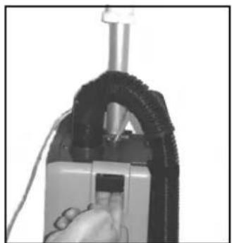
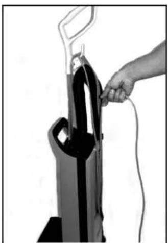
| 1. | Unplug the Power Cord from the electrical outlet. |
| 2. | If the Dust Bag Full" Indicator (15) not has been lightened during operation - the dust bag still have fi lling capacity. Open the dust housing cover to ensure that the dust bag not is full, replace if necessary. See also separate instructions for replacing the dust bag. Clean the bag housing, if necessary. |
| 3. | Wind up the cord (starting from the machine inlet side). |
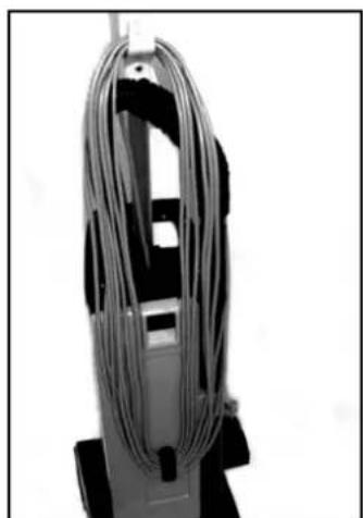
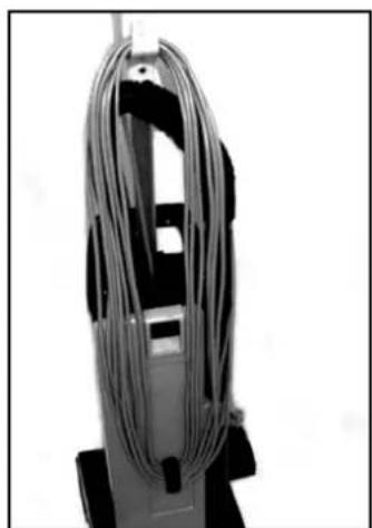
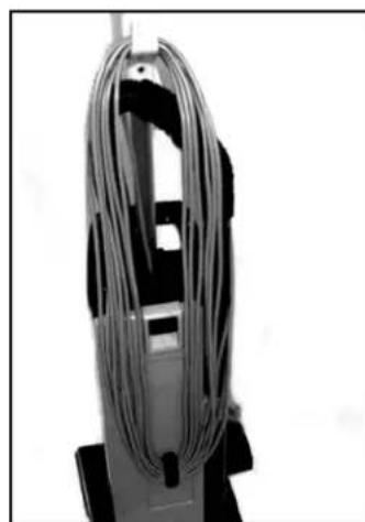
| 4. | Store the cord at the hook at the Dust lid cover and the hook at the handle. |
| 5. | Check the brush house. Remove any built-up carpet fi bers or debris from the brush and the brush housing. |
| 6. | Store the machine indoors in a clean, dry place. |
natural_image
Hand inserting a black rubber cloth into a white rack, no text or symbols visible3
natural_image
Close-up of a mechanical device with coiled metallic wires, no visible text or symbols4
SOMMAIRE
INSTRUCTIONS VISANT LA MISE À LA TERRE
IL EST INDISPENSABLE DE BIEN CONNAITRE L'APPAREIL
natural_image
Person using a vacuum cleaner to lift a hose, no visible text or symbols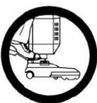
natural_image
Simple line drawing of a robotic arm inside a circular frame (no text or symbols)IMPORTANT!
IMPORTANT!
natural_image
White and black vacuum cleaner on a tiled floor, no visible text or symbols5
natural_image
Close-up of a hand operating a mechanical device with a black arrow pointing to the handle (no visible text or symbols)1
natural_image
Person using a leg exercise machine on a wooden floor (no text or symbols visible)2
UTILISATION DU TUBE (EN OPTION)
natural_image
Simple line drawing of a robotic arm inside a circular frame (no text or symbols)IMPORTANT!
natural_image
Close-up of a hand inserting a component into a device (no visible text or symbols)1
natural_image
Close-up of a hand using a tool to adjust or install a mechanical component (no visible text or symbols)2
UTILISATION DES OUTILS (EN OPTION)
natural_image
Close-up of a person's seat with a black walking stick and patterned fabric, no visible text or symbols3
natural_image
Close-up of a black cylindrical object on a white surface, possibly a tool or component (no text or symbols visible)3
natural_image
Simple line drawing of a robotic arm inside a circular frame (no text or symbols)IMPORTANT!
natural_image
Two-step diagram showing hands operating a vacuum cleaner device, with no visible text or symbols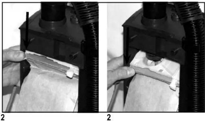
natural_image
Two-panel black-and-white photo showing hands operating a mechanical device with a tool, no visible text or symbolsnatural_image
Two-panel image showing a printer's internal structure and its assembly with arrows indicating parts of the printer's interior (no text or symbols present)REPLACEMENT OU NETTOYAGE DE LA BROSSE
natural_image
Close-up of a hand holding a black knob next to a dark object, with an arrow pointing to the knob (no visible text or symbols)2
natural_image
Close-up of a hand holding a dark object with a black arrow pointing to it, no visible text or symbols.3
natural_image
Close-up of a hand pressing down on a corrugated metal strip (no text or symbols visible)4
natural_image
Close-up of a hand holding a black mechanical component with a black arrow pointing to it (no visible text or symbols)6
natural_image
Close-up of a hand pressing a button on a car door, with an arrow indicating the button (no text or symbols visible)7
REPLACEMENT DU FILTRE HEPA
natural_image
Hand pressing a button on a wall-mounted device (no visible text or symbols)1
natural_image
Hand inserting a grid into a device (no visible text or symbols)2
natural_image
Hand inserting a card into a device (no visible text or symbols)3
natural_image
Close-up of a hand pressing down on a computer control panel (no visible text or symbols)4
REEMPLACEMENT DU FILTRE D'ÉVACUATION
natural_image
Hand placing a small object into a white panel with a gridded grille (no text or symbols visible)1
natural_image
Hand inserting a small electronic component into a device (no visible text or symbols)2
NETTOYAGE OU REMPLACEMENT DU PRÉFILTRE
natural_image
Close-up of a mechanical device with a coiled spring and attached housing (no visible text or symbols)1
natural_image
Close-up of a gloved hand placing a white paper liner into a baking tray (no text or symbols visible)2
natural_image
Close-up of hands holding a white rectangular object with an arrow pointing upward (no text or symbols visible)3
natural_image
Close-up of hands holding a white rectangular object with a patterned background (no visible text or symbols)5
APRÈS UTILISATION
natural_image
Hand inserting a cable into a black vacuum cleaner (no text or symbols visible)3
natural_image
Close-up of a mechanical device with coiled metallic wires, no visible text or symbols4
ÍNDICE
INTRUCCIONES PARA HACER LA TOMA A TIERRA
CONOZCA LA MÁQUINA
natural_image
Person using a vacuum cleaner to lift a hose, no visible text or symbols2
¡IMPORTANTE!
natural_image
Three-panel image showing hands operating a cable device with a switch, no visible text or symbols1 2 3
4 5
5
natural_image
Black and white photo of a vacuum cleaner on a tiled floor, no visible text or symbols5 6
6
natural_image
Close-up of a hand adjusting a mechanical device with a black arrow pointing to the component (no visible text or symbols)1
natural_image
Person using a leg presser on a wooden floor (no text or symbols visible)2
¡IMPORTANTE!
natural_image
Close-up of a hand inserting a component into a mechanical device (no visible text or symbols)1
natural_image
Close-up of a hand using a tool to adjust or install a component, with no visible text or symbols.2
natural_image
Close-up of a person's seat with a black handle and textured pattern, no visible text or symbols3
natural_image
Close-up of a black cylindrical object on a white surface, no visible text or symbols3
natural_image
Simple line drawing of a robotic arm inside a circular frame (no text or symbols)¡IMPORTANTE!
natural_image
Two black-and-white photos showing hands operating a mechanical device with a tire and cable, no visible text or symbols.1
1
natural_image
Two black-and-white photos showing a hand operating a mechanical device with a tool, no visible text or symbols.2
2
natural_image
Close-up of a hand holding a small mechanical component with arrows indicating direction (no visible text or symbols)3,4
natural_image
Close-up of a hand holding a mechanical device with a tool, no visible text or symbols5
natural_image
Close-up of a mechanical device with a black arrow pointing to a rectangular component, no visible text or symbols.5
natural_image
Close-up of a mechanical component with two black arrows pointing to a specific part (no visible text or symbols)6
CAMBIO DEL CEPILLO
natural_image
Close-up of a hand holding a black knob with an arrow pointing to it, next to an inset image of a padlock (no text or symbols visible)2
natural_image
Close-up of a hand holding a dark object with a black arrow pointing to it, no visible text or symbols.3
natural_image
Close-up of a hand pressing down on a coiled metal strip (no text or symbols visible)4
natural_image
Close-up of a hand holding a dark object with a black arrow pointing to it, no visible text or symbols.6
natural_image
Close-up of a hand pressing down on a car door, with an arrow indicating the finger movement (no text or symbols visible)7
natural_image
Hand inserting a small component into a device (no visible text or symbols)1
natural_image
Hand inserting a grid into a device (no visible text or symbols)2
natural_image
Hand inserting a card into a device (no visible text or symbols)3
natural_image
Close-up of a hand pressing down on a computer control panel (no visible text or symbols)4
natural_image
Hand pressing a button on a computer ventilation grille (no text or symbols visible)1
natural_image
Hand inserting a card into a device (no visible text or symbols)2
natural_image
Close-up of a mechanical device with a handle and clamped components (no visible text or symbols)1
natural_image
Close-up of a kitchen drawer containing white paper sheets, with a dough ball resting inside (no visible text or symbols)2
natural_image
Close-up of hands holding a white rectangular object with an upward arrow, no visible text or symbols3
natural_image
Close-up of hands holding a white strip with a patterned paper sheet (no visible text or symbols)5
natural_image
Hand inserting a black device into a white rack, no visible text or symbols3
natural_image
Close-up of a coiled cable or wire device mounted on a stand, no visible text or symbols4
CLARKE PRODUCT SUPPORT BRANCHES
U. S. A. Locations
PRODUCTION FACILITIES
Clarke ^® , Springdale, Arkansas 2100 Highway 265 Springdale, Arkansas 72764 (479) 750-1000 Customer Service - 1-800-253-0367 Technical Service - 1-800-356-7274
American Lincoln ^® , Bowling Green, Ohio 43402 1100 Haskins Road
SERVICE FACILITIES
Clarke ^® , Elk Grove, Illinois 60007 2280 Elmhurst Road (847) 956-7900
Clarke ^® , Denver, Colorado 80204 1955 West 13th Ave. (303) 623-4367
Clarke®, Houston, Texas 77040 7215 North Gessner Road 713-937-7717
SERVICE AND SALES FACILITY
American Lincoln ^® / Clarke, Madison Heights, Michigan 48071-0158 29815 John R. (810) 544-6300
American Lincoln® / Clarke, Marietta, Georgia 30066 1455 Canton Road (770) 973-5225
SALES AND DISTRIBUTION CENTER
Clarke®, Secaucus, NJ 07094 74 Henry Street (201) 864-5503
Clarke® US WARRANTY
This Clarke Commercial Product is warranted to be free from defects in materials and workmanship under normal use and service for a period of one year covering parts and labour (Motors and Belts warranted for two years) from the date of purchase, when operated and maintained in accordance with Clarke's Maintenance and Operations instructions.
This warranty is extended only to the original purchaser for use of the product. It does not cover normal wear parts such as electrical cable, rubber parts, hoses and motor brushes.
If diffi culty develops with the product, you should:
(a). Contact the nearest authorized Clarke repair location or contact the Clarke Service Operations Department, 2100 Highway 265, Springdale, 'Arkansas 72764, for the nearest authorized Clarke repair location. Only these locations are authorized to make repairs to the product under this warranty.
(b). Return the product to the nearest Clarke repair location. Transportation charges to and from the repair location must be prepaid by the purchaser.
(c). Clarke will repair the product and or replace any defective parts without charge within a reasonable time after receipt of the product.
Clarke's liability under this warranty is limited to repair of the product and/or replacement of parts and is given to purchaser in lieu of all other remedies, including INCIDENTAL AND CONSEQUENTIAL DAMAGES. THERE ARE NO EXPRESS WARRANTIES OTHER THAN THOSE SPECIFIED HEREIN. THERE ARE NO WARRANTIES WHICH EXTEND BEYOND THE DESCRIPTION OF THE FACE HEREOF. NO WARRANTIES, INCLUDING BUT NOT LIMITED TO WARRANTY OF MERCHANTABILITY, SHALL BE IMPLIED. A warranty registration card is provided with your Clarke product. Return the card to assist Clarke in providing the performance you expect from your new floor machine.
Clarke reserves the right to make changes or improvements to its machine without notice.
Always use genuine Clarke Parts for repair.
- CarpetMaster®
- CONTENTS
- IMPORTANT SAFETY INSTRUCTIONS
- WARNING!
- SAVE THESE INSTRUCTIONS
- GROUNDING INSTRUCTIONS
- GER!
- INTRODUCTION
- PARTS AND SERVICE
- RATING PLATE
- UNPACKING THE MACHINE
- KNOW YOUR MACHINE
- SET UP AND ASSEMBLY
- IMPORTANT!
- NOTE! Always disconnect the power cord before performing any machine maintenance.
- USING THE WAND (OPTIONAL)
- USING THE TOOLS (OPTIONAL)
- MAINTENANCE
- NOTE!
- CHANGING OR CLEANING OF THE BRUSH
- FILTERS - type of fi Iter may vary from different models
- CHANGING THE HEPA-FILTER
- CHANGING THE EXHAUST FILTER
- CLEANING OR CHANGING THE PRE FILTER
- AFTER USING THE MACHINE
- SOMMAIRE
- INSTRUCTIONS VISANT LA MISE À LA TERRE
- IL EST INDISPENSABLE DE BIEN CONNAITRE L'APPAREIL
- UTILISATION DU TUBE (EN OPTION)
- UTILISATION DES OUTILS (EN OPTION)
- REPLACEMENT OU NETTOYAGE DE LA BROSSE
- REPLACEMENT DU FILTRE HEPA
- REEMPLACEMENT DU FILTRE D'ÉVACUATION
- NETTOYAGE OU REMPLACEMENT DU PRÉFILTRE
- APRÈS UTILISATION
- ÍNDICE
- INTRUCCIONES PARA HACER LA TOMA A TIERRA
- CONOZCA LA MÁQUINA
- ¡IMPORTANTE!
- CAMBIO DEL CEPILLO
- CLARKE PRODUCT SUPPORT BRANCHES
- S. A. Locations
- PRODUCTION FACILITIES
- SERVICE FACILITIES
- SERVICE AND SALES FACILITY
- SALES AND DISTRIBUTION CENTER
- Clarke® US WARRANTY
Brand : Clarke
Model : CarpetMaster 212
Category : Vacuum Cleaner