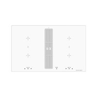
KMI8500.0WR - Cooker Küppersbusch - Free user manual and instructions
Find the device manual for free KMI8500.0WR Küppersbusch in PDF.


| Product type | Induction hob with integrated extractor hood |
| Brand | Küppersbusch |
| Model | KMI8500.0WR |
| Dimensions (H × W × D) | 170 × 830 × 515 mm |
| Weight | Approx. 30 kg (estimate) |
| Power supply | 380-415 V 3N~ 50/60 Hz; components 220-240 V |
| Total power | 7.4 kW (hob) + 0.115 kW (fan) + 0.01 kW (plasma) |
| Number of cooking zones | 4 induction zones |
| Zone sizes (W × L) | 19 × 21 cm each |
| Power per zone (normal/Power) | Front left 1.6 kW / 1.85 kW; rear left 2.1 kW / 3.0 kW; rear right 1.6 kW / 1.85 kW; front right 2.1 kW / 3.0 kW |
| Bridge function | Yes, up to 3.7 kW for two zones |
| Controls | Touch control keys |
| Special functions | Power Boost, automatic shut-off, timer, child safety lock, pan detection, residual heat indicator |
| Built-in fan | Yes, 4 speeds + delayed shut-off, downward extraction |
| Surface material | Ceramic glass |
| Cleaning | Special ceramic glass cleaner; dishwasher-safe grease filter |
| Safety | Child safety lock, automatic shut-off, overheat protection, pan overflow cut-off |
| Spare parts | Metal grease filter (ref. according to after-sales service), optional active charcoal filter |
| General information | User manual included, 84 pages in French |
Frequently Asked Questions - KMI8500.0WR Küppersbusch
User questions about KMI8500.0WR Küppersbusch
0 question about this device. Answer the ones you know or ask your own.
Ask a new question about this device
Download the instructions for your Cooker in PDF format for free! Find your manual KMI8500.0WR - Küppersbusch and take your electronic device back in hand. On this page are published all the documents necessary for the use of your device. KMI8500.0WR by Küppersbusch.
USER MANUAL KMI8500.0WR Küppersbusch
natural_image
Four white circles arranged in a 2x2 grid on a black background (no text or symbols)
KMI8500.0
Please read the users and installation instructions carefully before installation of the appliance and before starting to use it.
natural_image
Simple line drawing of a padlock with a curved handle and downward arrow indicating compression (no text or symbols)Wichtig


flowchart
graph TD
    A["1. Hand gestures"] --> B["2. Square icons with plus/minus symbols"]
    B --> C["3. Hand gestures with plus/minus symbols"]
    C --> D["→ Child-Lock icon"]
Kindersicherung L
Module (Powermanagement)
Powerstufe P
natural_image
Hand holding a pen writing on lined paper (no text or symbols visible)natural_image
Diagram of a mechanical or architectural component with directional arrows indicating movement (no text or symbols)Einbau
Wichtig
natural_image
Diagram of a curved structural component with an arrow indicating direction (no text or symbols)natural_image
Pure architectural line drawing of a modern building facade with no text or symbols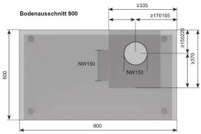
natural_image
Pure architectural line drawing of a modern building facade with no text or symbols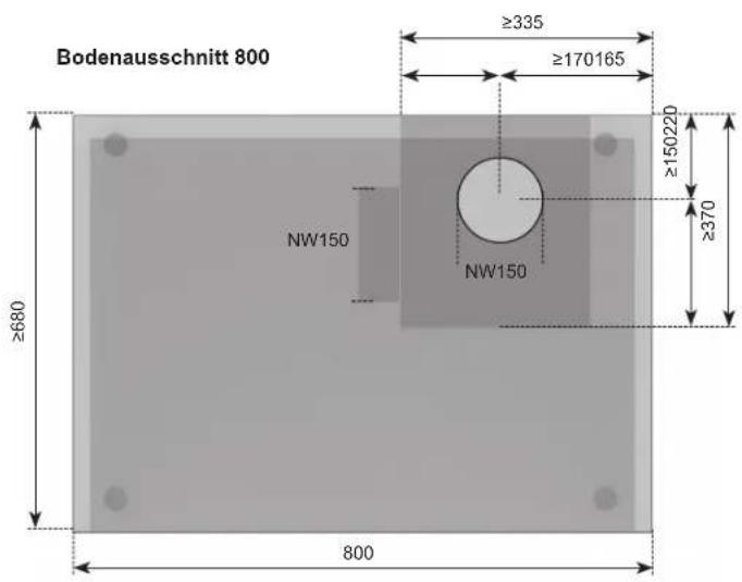
natural_image
Close-up of hands handling a white plastic sheet with a circular cap, no visible text or symbolsnatural_image
Close-up of a gray plastic mechanical component with a curved top and side gap (no text or symbols visible)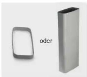
natural_image
Two 3D geometric shapes: a rounded square and a rectangular prism, labeled 'oder' (no other text or symbols)b
natural_image
3D rendered image of a gray curved pipe elbow joint (no text or symbols)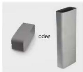
natural_image
Two gray 3D rectangular blocks, one labeled 'oder', against a plain background (no text or symbols on the blocks themselves)©
natural_image
Two gray 3D-printed mechanical parts, one with ribbed texture and the other with rounded edges (no text or symbols)d
natural_image
3D-rendered gray cylindrical object with smooth surface and no visible text or symbolse
natural_image
Exterior view of a metallic industrial device with a circular vent and power plug, labeled 'Lüfter' (no other text or symbols visible)f
natural_image
Diagram of a Dichtband device with a circular component and curved arm, no text or symbols presentSockelfi Iter (optional):
9
natural_image
3D model of a mechanical component labeled 'Aktivkohlefi Iter' (no other text or symbols visible)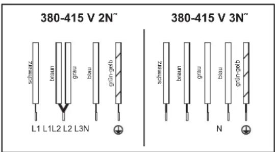
Technische Daten
Kochzonen
vorne links cm / kW
hinten links cm / kW
natural_image
Diagram of a computer monitor with a power cord and cable, showing signal lines and arrows (no text or symbols)Disposing of the packaging
Please ensure the environmentally-friendly disposal of the packaging that came with your appliance. Recycling the packaging material saves on resources and cuts down on waste.
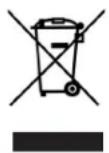
Disposing of old appliances
The symbol on the product or on its packaging indicates that this product may not be treated as household waste. Instead it must be handed over to the applicable collection point for the recycling of electrical and electronic equipment.
By ensuring that this product is disposed of correctly you will help to protect the environment and human health, which could otherwise be harmed through the inappropriate disposal of this product. For more detailed information about recycling this product, please contact your local city office, your household waste disposal service or the shop where you purchased the product.
Appropriate use
The hob is to be used solely for preparing food in the home or in similar environments. Similar environments:
- Using the hob in shops, offices and other similar working environments
• Using the hob in agricultural enterprises - Use of the hob by customers in hotels, motels and other typical living environments
• Use of the hob by B & Bs
It may not be used for any other purpose and may only be used under supervision.
For your information...
Please read this manual carefully before using your appliance. It contains important safety advice; it explains how to use and look after your appliance so that it will provide you with many years of reliable service.
Should a fault arise, please first consult the section on "What to do if trouble occurs?". You can often rectify minor problems yourself, thus saving unnecessary service costs.
Please keep this manual in a safe place and pass it on to new owners for their information and safety.
Contents
Safety Instructions and Warnings 25
For connection and operation 25
For the hob 25
For persons 26
Appliance description 27
Operating the hob with the sensor keys 28
Operation 29
The hob 29
Pan recognition 29
Operation time limit 29
Other functions 29
Protection against overheating (induction) 29
Cookware for induction hobs 30
How to cut power consumption 30
Power settings 30
Residual heat indicator 30
Switching the appliance into the standby mode ____ 31
Operating the keys 31
Switching on the hob and cooking zones 31
Switching off a cooking zone 31
Switching off the hob 31
Childproof lock 32
Switching off the childproof lock 32
Automatic switch-off (timer) 33
Minute minder (egg timer) 33
Power boost 34
Power management 34
Bridging function 34
Using the fan 35
Fan time lag 35
Cleaning and care 36
Glass ceramic hob 36
Hob fan 36
What to do if trouble occurs? 37
Installation 38
Safety instructions for kitchen unit fitters 38
Ventilation 38
Installation 38
Flush installation 39
Extraction air system assembly 41
Exhaust air duct components (inclusive) 41
7-pole fan plug connector 42
Electrical connection 43
Technical Data 43
Initial operation 43
For connection and operation
- The appliances are constructed in accordance with the relevant safety regulations.
- Connecting the appliances to the mains and repairing and servicing the appliances may only be carried out by a qualified electrician according to currently-valid safety regulations. For your own safety, do not allow anyone other than a qualified service technician to install, service or repair the product.
- If the mains supply cable of this appliance is damaged, it has to be replaced by the manufacturer, the Customer Service of the manufacturer or by another qualified person to avoid danger.
- The appliance may not be operated with an external timer or an external telecontrol system.
For the hob
- Never allow the induction hob to operate unattended, as the high power setting results in extremely fast reactions.
- When cooking, pay attention to the heat-up speed of the cooking zones. Avoid boiling the pots dry as there is a risk of the pots overheating!
- Do not place empty pots and pans on cooking zones which have been switched on.
• Take care when using simmering pans as simmering water may dry up unnoticed, resulting in damage to the pot and to the hob for which no liability will be assumed. - It is essential that after using a cooking zone you switch it off with the respective minus key and not just with the pan recognition device.
• Overheated fats and oils may spontaneously ignite. Always supervise the preparation of food with fats and oils. Never extinguish ignited fats and oils with water! Switch the appliance off and then carefully cover the flame, for example with a lid or an extinguisher blanket.
• The glass ceramic surface of the hob is extremely robust. You should, however,
avoid dropping hard objects onto the glass ceramic hob. Sharp objects which fall onto your hob might break it.
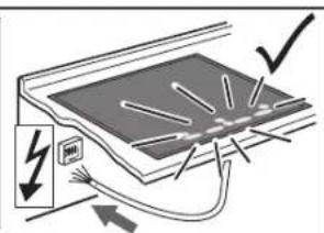
- There is a risk of electric shocks if the glass ceramic hob develops fractures, cracks, tears or damage of any other kind. Immediately switch off the appliance. Disconnect the fuse immediately and call Customer Service.
- If the hob cannot be switched off due to a defect in the sensor control immediately disconnect your appliance and call Customer Service.
• Take care when working with home appliances! Connecting cables must not come into contact with hot cooking zones. - Risk of fire: never store items on the hob.
- The glass ceramic hob should not be used as a storage area.
- Do not put aluminium foil or plastic onto the cooking zones. Keep everything which could melt, such as plastics, foil and in particular sugar and sugary foods away from hot cooking zones. Use a special glass scraper to immediately remove any sugar from the ceramic hob (when it is still hot) in order to avoid damaging the hob.
• Metal items (pots and pans, cutlery, etc.) must never be put down on the induction hob since they may become hot. Risk of burning! - Do not place combustible, inflammable or heat deformable objects directly underneath the hob.
- Metal items worn on your body may become hot in the immediate vicinity of the induction hob. Caution! Risk of burns! Non-magnetisable objects (e.g. gold or silver rings) are not affected.
- Never use the cooking zones to heat up unopened tins of food or packaging made of material compounds. The power supply may cause them to burst!
- Keep the sensor keys clean since the appliance may consider dirt to be finger contact. Never put anything (pans, tea towels etc.) onto the sensor keys!
- If food boils over onto the sensor keys, we advise you to activate the OFF key.
- Hot pans and pots should not be placed near the sensor keys nor should they cover them since this will cause the appliance to switch off automatically.
- Place the pan as close to the centre of the cooking zone as possible.
- Whenever possible, use the back cooking zones for large pans so that the sensor keys are not heated up too much (touch control overheating; error message E2, touch control cut off).
- Activate the childproof lock if there are any pets in the home which could make contact with the hob.
- Never clean the glass ceramic hob with a steam cleaner or similar appliance!
- Make sure there are no items (e.g. cleaning cloths) right next to the hob extractor. They could be sucked in by the air current. Liquids and small items must always be kept away from the appliance.
- Never operate the appliance without installing a filter.
- Filter with too much fat deposits causes fire hazard!
- Constant supervision is essential when deep-frying; flambéing is not permitted.
- A sufficient supply of inlet air must be provided when operating wood, coal, gas or oil heaters requiring a chimney.
- The permissible negative pressure which results from the hood in the location of the heaters requiring a chimney may not exceed 4 Pa (0.04 mbar) as this results in a risk of poisoning.
• Vapour also emits moisture into the air in the kitchen during the cooking process.
- Only a little moisture is removed from the vapours in the convection air mode. This is why a sufficient supply of fresh air must always be provided, e.g. by opening the window or using domestic ventilation systems.
• Always make sure that the indoor climate is normal and comfortable (45 - 60 % humidity).
- Switch the hob extractor down to a lower setting for around 20 minutes or activate the automatic delayed stop function every time the hob extractor is used in the convection air mode.
For persons
• These appliances may be used by children aged 8 years and over and by persons with physical, sensory or mental impairments or by persons who lack experience and/or know-how, provided they are supervised or have been instructed in the safe used of the appliance and have understood the risks relating to the appliance. Children may not play with the appliance. Cleaning and maintenance by the user may only be carried out by children when they are supervised.
- The surfaces of the heating and cooking zones become hot during use. Keep small children away at all times.
- Only hob protective grids and hob covers produced by the hob manufacturer or the manufacturers of the hob protective grids and hob covers authorised by the manufacturer in the instructions for use may be used. The use of unsuitable hob protective grids and hob covers may result in accidents.
- Persons with cardiac pacemakers or implanted insulin pumps must make sure that their implants are not affected by the induction hob (the frequency range of the induction hob is 20-50 kHz).
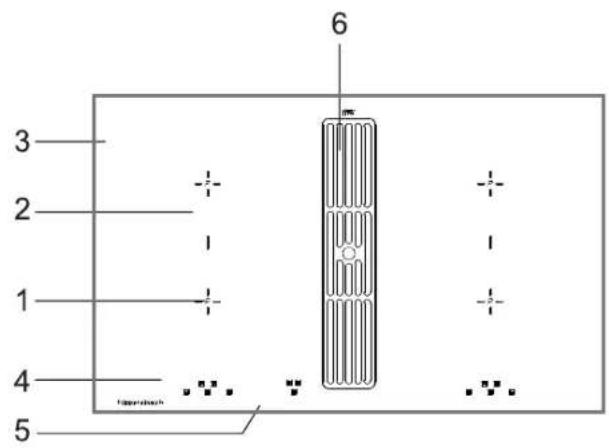
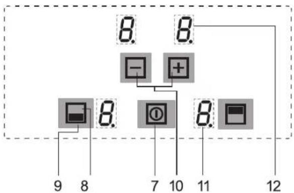
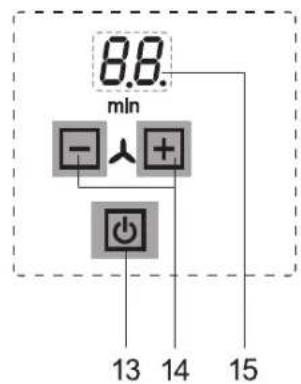
flowchart
graph TD
    A["8. 8."] --> B["-"]
    A --> C["+"]
    B --> D["7"]
    C --> E["10"]
    D --> F["8. 8."]
    E --> G["8. 8."]
    F --> H["9 8"]
    G --> I["11"]
    H --> J["12"]
The decorative design may deviate from the illustrations.
- Induction cooking zone front left
- Induction cooking zone back left
- Glass ceramic hob
- Touch control panel
- Standby key and fan controls
- Fan
- ON / OFF key (hob)
-
Cooking zone selection key
-
Symbol for locating the position of a cooking zone on the glass ceramic hob
-
Plus key (raise) / Minus key (lower)
- Power setting indicator
- Timer indicator
- Standby key
- Minus key /Plus key Ventilation
- Fan indicator
Operating the hob with the sensor keys
The glass ceramic hob is operated with touch control sensor keys. The sensor keys are operated as follows: lightly touch a symbol on the surface of the ceramic glass plate. A buzzer will indicate when the controls have been operated correctly. The touch control sensor key will be indicated as a »key« from now on.
Standby key 3)
This key is used to switch the entire hob operational. It is, as it were, the main switch. When the hob has been switched off with this key, it will remain on standby for approx. another 120 min.
Attention! The residual heat indicator will no longer operate when the appliance has completely switched off.
ON/OFF key ☐7) Cooking zones left or right
This key is used to switch the left or right cooking zones on and off.
Cooking zone selection key; e.g. front ☐(3)
Pressing one of the cooking zone selection keys available will select a cooking zone, for which the Plus key or the Minus key may be used to set the cooking level.
Minus key ☐ Plus key (10)
These keys are used to set the cooking levels, the automatic switch-off device and the minute minder.
The Minus key reduces the setting and the Plus key raises it.
Power setting indicator (1)
The power setting indicator shows the power setting which has been selected, or:
lights up brightly, showing Cooking zone has been selected
H Residual heat indicator
P Power boost
L ____ Childproof lock
Bridging function
ER03 Error message
Control lamp Timer function
Minus key /Plus key Ventilation (14)
These key are used to operate the fan (extractor fan). It can be operated independently of the hob.
Fan indicator

fan setting
min fan time lag
The hob
The hob is equipped with an induction cooking mode. An induction coil underneath the glass ceramic hob generates an electromagnetic alternating field which penetrates the glass ceramic and induces the heat-generating current in the pot base.
With an induction cooking zone the heat is no longer transferred from a heating element through the cooking pot into the food being cooked; instead the necessary heat is generated directly in the container by means of induction currents.
Advantages of the induction hob
- Energy-saving cooking through the direct transfer of energy to the pot (suitable pots/pans made of magnetisable material are required).
- Increased safety as the energy is only transferred when a pot is placed on the hob.
- Highly effective energy transfer between an induction cooking zone and the base of a pot.
- Rapid heat-up.
- The risk of burns is low as the cooking area is only heated through the pan base; food which boils over does not stick to the surface.
- Rapid, sensitive control of the energy supply.
Pan recognition U
If a cooking zone is switched on and there is no pan on the zone or if the pan is too small, there will be no transmission of power. A blinking U in the power level indicator points this out.
If a suitable pot or pan is placed on the cooking zone, the power setting will switch on and the power setting indicator will light up.
The power supply will be cut off when the pan is removed and the power setting indicator will indicate a blinking
If the pots and pans placed on the cooking zone are of smaller dimension, and the pan recognition still switches on, less power will be supplied.
Pan recognition limits
The base of pots and pans must be of a certain diameter; if it is not, the induction heat will not be switched on. Always place pots and pans in the middle of a cooking zone in order to achieve the best efficiency.
| Cooking zone diameter Recommended pan base minimal diameter |
| 190 x 210 mm 120 mm |
Important
The minimum diameter required to activate the pan recognition device may vary according to the type of pot or pan used!
Operation time limit
The induction hob has an automatic time limit function.
The duration of continuous use of each cooking zone depends on the cooking level selected (see chart).
| Selected power setting Operation time limitin hours | |
| 1, 2 | 6 |
| 3, 4 | 5 |
| 5 | 4 |
| 6, 7, 8, 9 | 1,5 |
This requires that the setting of a respective cooking zone is not adjusted during use.
If the operation time limit has been activated, the cooking zone will switch off, a short signal will sound and an H will appear in the display.
The automatic switch-off function overrules the operation time limit, i.e. the cooking zone is only switched off when the period of time of the automatic switch-off device has expired (e.g. automatic switch-off after 99 minutes and cooking level 9 is possible).
Other functions
If two or more sensor keys are pressed at the same time (e.g. when a pan is mistakenly put onto a sensor key) no function will be activated. An acoustic signal sounds and ER03 will appear. After a few seconds the appliance will switch off. Please remove the item located in front of the sensor keys.
Protection against overheating (induction)
If the hob is used at full power for a longer period, it will not be possible to cool down the electronics system as required at a high room temperature. In order to ensure that no excessive temperatures occur in the electronics system the power of the cooking zones may be reduced automatically.
Should E2 or ER21 be displayed frequently during normal use of the hob and at normal room temperature, it is likely that cooling is not sufficient.
This may occur if kitchen units have no openings. The installation may have to be checked (see the section on Ventilation).
Cookware for induction hobs
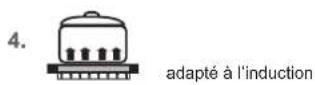
Cookware for induction cooking zones must be made of metal and have magnetic properties. The base must be sufficiently large.
Only use pots with a base suitable for induction.
| Suitable cookware Unsuitable cookware | |
| Enamelled steel pots with a thick base | Pots made of copper, stainless steel, aluminium, oven-proof glass, wood, ceramic and terracotta |
| Cast iron pots with an enam-elled base | |
| Pots made of multi-layer stainless steel, stainless ferrite steel and aluminium with special base | |
This is how to establish the suitability of a pot:
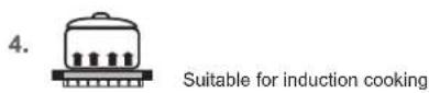
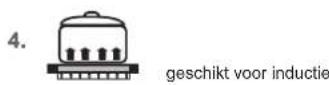
Conduct the magnet test described below or make sure that the pot bears the symbol for suitability for cooking with induction current.
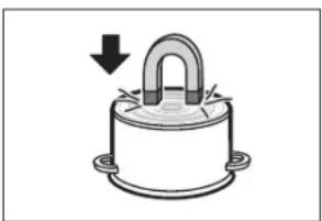
Magnet test
Move the magnet towards the base of your cookware. If it is attracted, you can use the cookware on the induction hob.
natural_image
Simple line drawing of a mechanical component with a curved top and base, no text or symbols present.Important
When using pans suitable for induction from certain manufacturers, noises may occur which are attributable to the design of these pans.
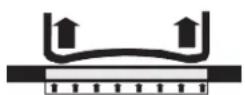
wrong wrong
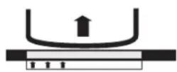
↑ ↑ ↑ ↑ ↑
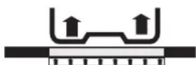
wrong
Wrong: the base of the pan is curved. The electronic unit cannot determine the temperature correctly.
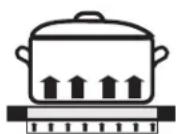
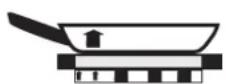
correct
Right: suitable cookware!
How to cut power consumption
The following are a few useful hints to help you cut your consumption of energy and use your new induction hob and the cookware efficiently.
- Pressure cookers are particularly low on energy and time required thanks to the pressure and the fact that they are tightly closed. Short cooking times mean that vitamins are preserved.
- Always make sure that there is sufficient fluid in your pressure cooker since the cooking zone and the cooker may be damaged as a result of overheating if the pressure cooker boils dry.
• Always close cooking pots with a suitable lid. - Use the right pot for the quantity of food you are cooking. A large pot which is hardly filled will use up a lot of energy.
Power settings
The heating power of the cooking zones can be set at various power levels. In the chart you will find examples of how to use each setting.
| Setting Suitable for | |
| 0 | Off, using residual heat |
| 1-2 | Simmering small portions (lowest setting) |
| 3 | Simmering |
| 4-5 | Simmering big portions Continuing to roast large pieces of meat until they are cooked through |
| 6 | Roasting, getting juices |
| 7-8 | Roasting |
| 9 | Bringing to the boil, browning, roasting |
| P | Power boost (highest power output) |
A higher power level may need to be selected for cooking pots without a lid.
Residual heat indicator
The glass ceramic hob is equipped with an H as a residual heat indicator. As long as the H lights up after the cooking zone has been switched off, the residual heat can be used for melting food or for keeping food warm.

The cooking zone may still be hot when the letter H no longer lights up. Risk of burns!
The glass ceramic is not directly heated in the case of an induction cooking zone; it is only heated up by heat reflected by the pan.


Cooking zone selection keys

Switching the appliance into the standby mode
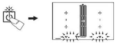
This standby key [da] used to switch the entire hob operational. It is, as it were, the main switch. An automatic test of the controls will be carried out first of all, and the displays will light up briefly. When the hob has been switched off with this key, it will remain on standby for approx. another 120 min. Important! The residual heat indicator will no longer operate when the appliance has completely switched off.
Operating the keys
The controls described here expect the pressing of a (selection) key to be followed by the pressing of a subsequent key. The next key will always need to be pressed within 10 seconds, otherwise the selection will be deleted.
Switching on the hob and cooking zones
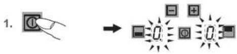
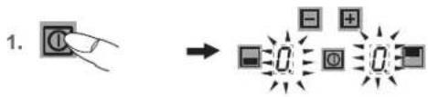
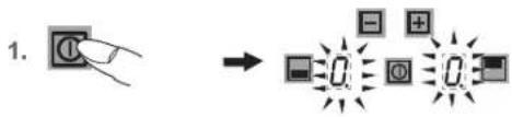
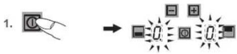
- Press the ON/OFF key of the hob (Bprox. 1 sec.) until the power setting 0 appears. The controls are ready for operation.
- Then press a cooking zone selection key (e.g. for front). The selected power setting indicator will light up brightly.
- Use the Plus key ☐ or Minus key ☐ to select a power setting. The plus key will activate power setting 1 and the minus key power setting 9.
- Immediately put cookware suitable for induction cooking onto the cooking zone. The pan recognition device will activate the induction coil. The pot or pan will be heated up. The Symbol will appear until a metal cooking pot is placed onto the cooking zone. If no pot is placed on the cooking zone it will switch off after 10 minutes for reasons of safety. Please refer to the Section on »Pan recognition«.
Repeat items 2 to 4 in order to cook on other cooking zones at the same time.
Switching off a cooking zone
- Press the required cooking zone selection key (e.g. front). The selected power setting indicator will light up brightly.
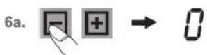
- a) Press the Minus key several times until the power setting indicator shows 0 or b) Press the on/off key for the hob. The entire hob will be switched off (all the cooking zones are switched off).
Switching off the hob
- Press the on/off key ☑ the hob. The hob will be switched off, irrespective of any settings.
Childproof lock L
The childproof lock serves the purpose of preventing children from switching on the induction hob either accidentally or intentionally. The controls are blocked here.
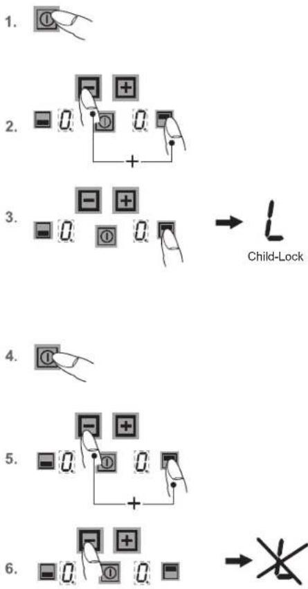
flowchart
graph TD
    A["1. Hand icon"] --> B["2. Button: 0, +"]
    B --> C["3. Button: -0, +"]
    C --> D["4. Hand icon"]
    D --> E["5. Button: 0, +"]
    E --> F["6. Button: -0, +"]
    F --> G["→ Child-Lock symbol"]
Switching on the childproof lock
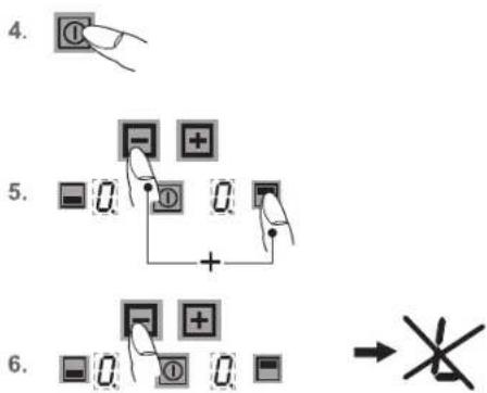
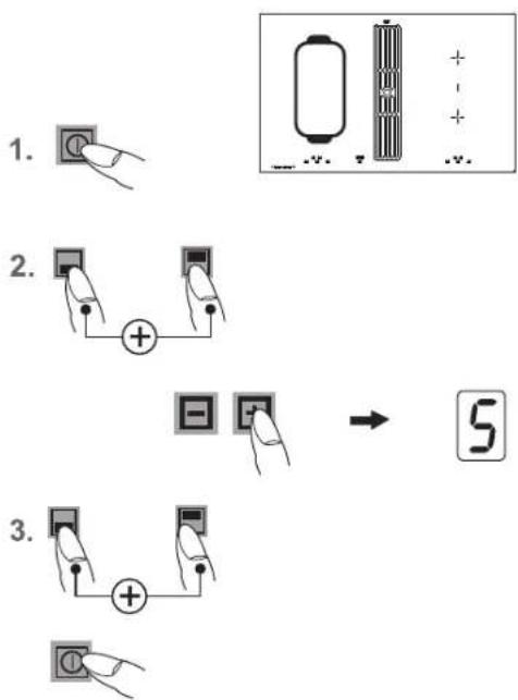
- Press the on/off key of the hob (approx. 1 sec.) in order to switch the entire hob on.
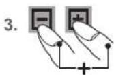
- Then immediately press the Minus key ☐ and the cooking zone selection key for front right ☑ simultaneously.
- Then press the cooking zone selection key in order to activate the childproof lock. The power setting indicators will show an L for child lock, the controls will be disabled and the hob will switch off.
Switching off the childproof lock
- Press the ON/OFF key ①
- Then immediately press the Minus key and the cooking zone selection key for front right simultaneously.
- Then press the Minus key in order to deactivate the child-proof lock. The L will go off.
De-activating the childproof lock for one cooking procedure only
This is only possible if the childproof lock has been switched on according to points 1-3.
- Press the ON/OFF key .
- Then immediately press the Minus key □ and the right cooking zone selection key □ simultaneously. Once the L has gone off, the user may switch a cooking zone on.
- When the hob is switched off the childproof lock will be activated again (switched on).
Important
In the event of a power cut the childproof lock will not be cancelled, i.e. it remains activated.
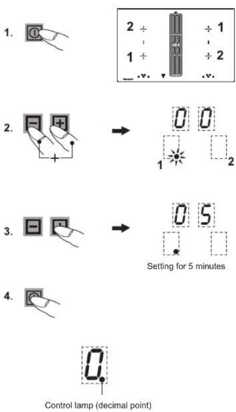


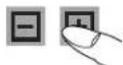


Setting for 12 minutes

Automatic switch-off (timer) Ⓤ
The automatic switch-off device is used to automatically switch off any cooking zone after an adjustable period of time. Cooking times ranging from 01 to 99 minutes can be set.
- Switch on the hob. Switch on one or more cooking zones and select the required power settings.
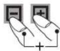
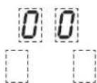
- Repeatedly press the Plus key and the Minus key simultaneously until the control lamp (decimal point) of the cooking zone of your choice lights up. The timer indicator will light up brightly.
- Then immediately press the Plus key + or the Minus key - to enter the cooking time. In order to programme the automatic switch-off device for another cooking zone, repeatedly press the Plus key + and the Minus key simultaneously until the control lamp (decimal point) of the respective power level indicator lights up.
- The cooking zone will be switched off when the time has lapsed. A signal will sound for a while and can be switched off by pressing any key (except the ON/OFF key).
Important
- In order to check on the time that has lapsed (automatic switch-off device), repeatedly press the Plus key + and Minus key - simultaneously until the control lamp (decimal point) of the respective cooking zone indicator lights up. The setting displayed can be read and changed.
- Terminating the function of the timer: Select the respective cooking zone and use the Minus key to make a setting.
Minute minder (egg timer)
The cooking zones are switched off.
- Switch on the hob.
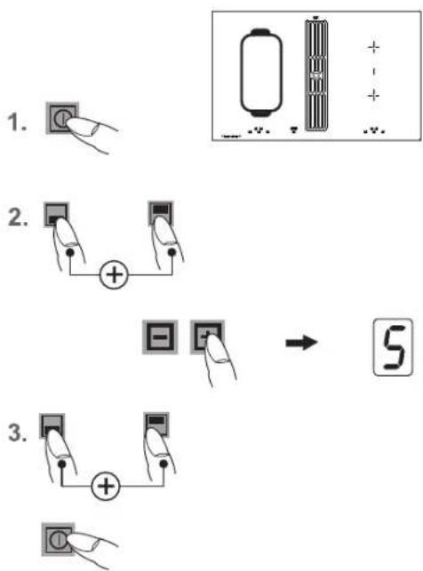
- Press the Plus key ☐ and the Minus key ☐ simultaneously once. The timer indicator will light up brightly. The control lamp (decimal point) may not light up in the cooking setting displays.
- Then immediately use the Plus key ⊕ or the Minus key ⊖ to set the time in minutes.
- Once the time has lapsed a signal will sound for a while and can be switched off by pressing any key (except the OFF key).
Important
The minute minder will also remain in operation when the right or left side of the hob is switched off. Switch the left or right side of the hob on to adjust the time.
Modules (power management)
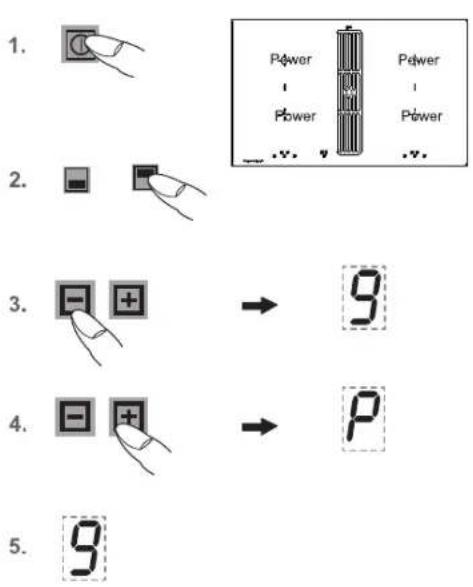
Power boost P
The power boost setting makes additional power available for induction cooking zones. A large quantity of water can be brought to the boil very quickly. The power boost setting operates for 5 minutes, after which the power level is automatically reduced to power setting 9.
- Switch on the hob.
- Then press a cooking zone selection key (e.g. for back). The selected power setting indicator will light up brightly.
- Press the Minus key ☐ once in order to set the highest power setting (9).
- Press the Plus key ☐ once in order to activate the power boost setting. The power setting indicator will show a P.
- After 5 minutes the power boost setting will switch off automatically. The P will go off and the power level will switch down to 9.
Important
Press the minus key to prematurely de-activate the power setting. Attention. risk of overheating! Do not heat up any oil/frying fat with the power boost setting.
Power management
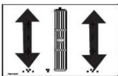
For technical reasons two cooking zones always comprise a module and have a maximum power level.
If this power range is exceeded when a higher power setting level or the power boost function is switched on the power management system will reduce the power setting of the corresponding cooking zone of the module. The display for this cooking zone will initially blink, after which the highest-possible power setting will be consistently displayed.
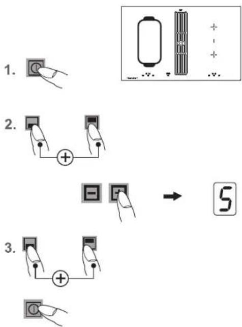
Bridging function
The front and the rear cooking zones may be activated together for a cooking process (bridging function). This enables larger cookware to be used.
- Switch on the hob.
- Press the two cooking zone selection keys of the front and back cooking zones simultaneously to activate the bridging function. The bridging function is activated, the symbol appears. Use the Plus key by Minus key to select a power setting.
- To deactivate the two cooking zone selection keys press them simultaneously again or switch off the hob.
Important
The roaster or the pot will need to cover at least half of the cooking zones used in order to be recognised by the pan recognition device!

The open aluminium cover does not need to be removed.
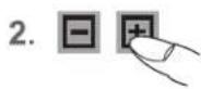
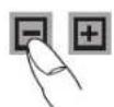
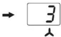
Using the fan
The fan is located in the middle of the hob with the extractor facing downwards.
Remove the glass cover before initial operation of the fan. The cover does not need to be removed from models with an open aluminium cover.
Important
Do not place the cover on the induction hob! Risk of burning!
Switching the fan on and off
- Press the standby key (approx 1 sec.), until the appliance switches into the standby mode.
- Press the fan Plus key
You will then be able to select a power setting, 1,2,3 or 4, by using the Plus for Minus key. The symbol for the fan will light up. The intensive power setting 4 operates for 10 minutes, after which the power level is automatically reduced to power setting 3.
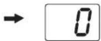
- Press the fan Minus key until 0 is shown in order to switch fan off.
Hint
In order to ensure that extraction functions well with tall cooking pots (e.g. pots used for cooking asparagus), you can place a wooden spoon under the lid of the pot.
Fan time lag
The fan time lag is used after cooker in order to remove cooking odours. The filter is also dried in the fan.
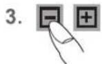
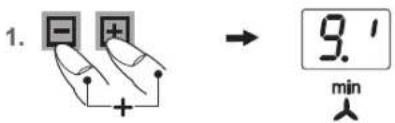
- Press the fan Plus and Minus keys simultaneously. The fan time lag of 10 minutes will be activated. The symbol for the fan time lag will light up min
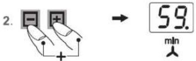
- Pressing the Plus and Minus keys simultaneously again will set 60 minutes.
- The time lag function is deactivated by pressing the two keys simultaneously again.
The fan setting can be freely adjusted or changed when the fan time lag is switched on.
Stop delay time
The fan motor should continue operating for another 10-10 minutes every time the hob has been used for cooking.
This guarantees optimal functioning and the removal of remaining cooking steam.
When using a recirculating air filter, please always allow for a stop delay time of 10 - 60 minutes in order to optimally remove cooking odours.
When the fan is switched on again, in rare cases the odour molecules present in the filter may be combined with steam so that they are detected again. These remaining odours will disappear when the fan continues to operate.
Important
When the convection air mode is in operation, ventilation must be sufficient in order for the air humidity to be removed.
- Switch the hob off and let it cool down before you clean it.
- Never clean the glass ceramic hob with a steam cleaner or similar appliance!
- When cleaning make sure that you only wipe lightly over the on/off key. The hob may otherwise be accidentally switched on!
Glass ceramic hob
Important! Never use aggressive cleaning agents such as rough scouring agent, abrasive saucepan cleaners, rust and stain removers etc.
Cleaning after use
1 Always clean the entire hob when it has become soiled. It is recommended that you do so every time the hob is used. Use a damp cloth and a little washing up liquid for cleaning. Then dry the hob with a clean dry cloth to ensure that there is no detergent left on the surface of the hob.
Weekly cleaning
2 Clean the entire hob thoroughly once a week with a commercial glass ceramic cleaning agent.
Please follow the manufacturer's instructions carefully.
When applied, the cleaning agent will coat the hob in a protective film which is resistant to water and dirt. All the dirt will remain on the film and can then easily be removed. Then rub the hob dry with a clean cloth. Make sure that no cleaning agent remains on the surface of the hob since this will react aggressively when the hob is heated up and will change the surface.
Specific soiling
Heavy soiling and stains (limescaling and shiny, mother-of-pearl-type stains) can best be removed when the hob is still slightly warm. Use commercial cleaning agents to clean the hob. Proceed as outlined under Item 2.
natural_image
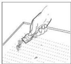
Hand holding a pen writing on lined paper (no visible text or symbols)First soak food which has boiled over with a wet cloth and then remove remaining soiling with a special glass scraper for glass ceramic hobs. Then clean the hob again as described under Item 2.
Remove burnt sugar and melted plastic immediately - when it is still hot - with a glass scraper.
Then clean the hob again as described under Item 2 once it has cooled down.
Grains of sand which may get onto the hob when you peel potatoes or clean lettuce may scratch the surface of the hob when you move pots around. Make sure that no grains of sand are left on the hob.
Changes in the colour of the hob will not affect the function and the stability of the glass ceramic material. These colour changes are not changes in the material but food residues which were not removed and which have burnt into the surface.
Shiny spots result when the base of the cookware rubs on the surface of the hob, particularly when cookware with an aluminium base or unsuitable cleaning agents are used. They are difficult to remove with standard cleaning agents.
You may need to repeat the cleaning process several times. In time, the decoration will wear off and dark stains will appear as a result of using aggressive cleaning agents and faulty pan bases.
Hob fan
Cleaning the metal grease filters
Clean the metal grease filters in the dishwasher or in mild soapy water at least once a month or in the event of excessive grease deposits and/or intensive use.
To remove the filter, lift up the fan cover and lift the U-shaped stainless steel ventilation plate in the suction intake opening upwards to remove it from the fan. Now remove the filter. To do so, press the lock in the recessed handle downwards and remove the filter.
The filter can be rinsed in a dishwasher. Stand the filter upright in the dishwasher. Please use only rinse aid that is suitable for use with aluminium in order to avoid damaging and discolouring the filters. Never rinse right next to glasses or light-coloured porcelain.
Do not operate the fan without grease filters!
After rinsing the filter, dry it and replace it in the fan.
Please make sure that the recessed handle is visible after you have replaced the filter. If possible, wipe the easily accessible inside of the fan with a cloth dampened with detergent every time you replace a filter, while at the same time paying attention to protruding parts in the inside of the fan.
Fan cleaning and care
The fan is best cleaned every time you clean the filters. Condensation water may collect under the filter after water has boiled rapidly with the lid of the pot removed. This is quite normal. The water should, however, be removed and the inside of the fan cleaned.
The ventilation openings in the cover ensure that residual moisture resulting from cooking and cleaning can escape if necessary when the fan is not in operation and the cover is on.
Please clean the filter and the inside of the fan if unpleasant remaining odours escape.
The fan is best cleaned with a soft damp cloth and mild soapy water.
Service
The filter must remain accessible.
Replace the charcoal filter mats of a charcoal filter every 5 to 24 months.
Replace the charcoal filter mats of plasma filters at least every 5 years.
To do so, open the cover of the casing and replace the charcoal filter mats.
Interference with and repairs to the appliance by unqualified persons are dangerous as they can result in an electric shock or a short circuit. Do not interfere with or try to repair the appliance; this could cause injury to persons and damage to the appliance. Always have such work done by an expert, e.g. a Customer Service technician.
Important
If your appliance is faulty, please check whether you can remove the problem yourself by consulting these instructions for use.
You may be able to rectify some problems yourself. They are described below.
The fuses blow regularly?
Contact a technical customer service or an electrician!
You can't switch your induction hob on?
- Has the wiring system (fuse box) in the house blown a fuse?
- Has the hob been connected to the mains?
- Are the sensor keys locked (childproof lock)?
- Are the sensor keys partly covered by a damp cloth, fluid or a metallic object? Please rectify.
- Are you using unsuitable cookware? See the section on "Cookware for induction hobs".
The symbol r^j will blink and a time-limited continuous signal will sound.
Food which has boiled over, cookware or other items are causing the touch control sensor keys to be consistently operated.
Remedy: clean the surface or remove the item. To delete the symbol press the same key or switch the hob off and on.
Error code E2 is indicated?
The electronic unit is too hot. Check the installation of the hob. Make sure that there is sufficient ventilation.
See the section on "Protection against overheating".
See the section on "Ventilation".
Error code E8 is indicated?
Fault on the left or right fan. The suction opening is blocked or covered or the fan is defect. Check the installation of the hob. Make sure that there is sufficient ventilation.
See the section on "Protection against overheating".
See the section on "Ventilation".
Error code U400 is indicated?
The hob has been incorrectly connected. The controls will switch off after 1sec. and a continuous signal will sound. Connect the appliance to the appropriate power supply.
An error code (ERxx or Ex) is indicated?
The appliance has developed a technical defect. Please call Customer Service.
The pot sign appears ?
A cooking zone has been switched on and the hob is expecting a suitable pot or pan to be placed on the cooking zone (pan recognition).
Only when a pot has been placed on the cooking zone will power be supplied.
The pot sign still appears, even though a pot or pan was placed on the hob?
The cookware is unsuitable for induction cooking or the pot or pan is too small.
Is the cookware you are using making noises?
This is due to technical reasons; the induction hob and the pot are not at risk.
Does the cooling fan still operate after it has been switched off?
This is normal since the electronic unit is being cooled down.
Is the hob making noises (clicking or cracking sounds)?
This is for technical reasons and cannot be avoided.
Does the hob have tears or cracks?
There is a risk of electric shocks if the glass ceramic hob develops fractures, cracks, tears or damage of any other kind. Immediately switch off the appliance. Disconnect the fuse in the building immediately and call Customer Service.
Safety instructions for kitchen unit fitters
- Veneers, adhesives and plastic surfaces of surrounding furniture must be temperature resistant ( >75^ ). If the veneers and surfaces are not sufficiently heat resistant they may become deformed.
- Ensure that all live connections are safely insulated when installing the hob.
- Cover strips between the wall and the worktop behind the hob which are made of solid wood are permissible as long as minimum clearances in accordance with the installation diagrams are maintained.
- Minimum clearances of the hob cut-out towards the rear are to be maintained in accordance with the installation diagram.
- For installation directly next to a tall cupboard, a safety distance of at least 50 mm must be ensured. The side surface of the tall cupboard should be fitted with heat resistant material. Due to working requirements, however, the distance should be at least 300 mm.
- The packaging materials (plastic foil, polystyrene, nails etc.) must be kept out of reach of children as these parts are potentially dangerous. Small parts can be swallowed and there is a danger of plastic sheeting causing suffocation.
Ventilation
- The induction hob is fitted with a fan that switches on and off automatically. The fan starts slowly when the electronic system temperatures exceed a specific limit. When the induction hob is used intensively, the fan will switch to a greater velocity. Once the electronic system has cooled down sufficiently, the fan will reduce its velocity and switch off again automatically.
- Clearance between the induction hob and kitchen furniture or built-in units must provide for sufficient ventilation of the induction hob.
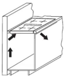
- If the power level of a cooking zone is automatically raised or lowered (see section on thermal cut-off device) it is likely that the cooling system does not cool sufficiently. In this case we recommend that the back wall of the bottom kitchen unit in the area of the worktop cut-out be opened and that the front transverse strip of the unit be removed over the entire width of the appliance in order to promote the circulation of air.
- In order to better ventilate the hob, it is recommended that an air gap of 5 mm be left at the front.
natural_image
Diagram of a mechanical or electrical component with directional arrows indicating movement (no text or symbols)Installation
Important
- Remove any transverse strips underneath the worktop at least in the area of the worktop cut-out.
- When installing the appliance on top of a drawer it is essential to ensure that no sharp items are stored in the drawer since these could become bent on the underside of the hob and prevent the drawer from being opened and closed.
- If a shelf has been inserted underneath the hob, there must be a clearance of at least 20 mm to the underside of the hob in order to ensure that the hob is sufficiently ventilated.
- To avoid danger of fire, make sure that no combustible objects which could easily catch fire or become deformed on exposure to heat are directly next to or under the surface.
Sealing of the hob
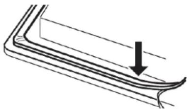
Before installation, correctly insert the sealing unit delivered with the hob.
natural_image
Diagram of a curved structural component with an arrow indicating direction (no text or symbols)- No liquids may penetrate between the edge of the hob and the worktop or between the hob and the wall and come into contact with any electrical appliances.
- When installing a hob into an uneven worktop, e.g. with a ceramic or similar covering (tiles etc.), the seal on the hob is to be removed and the seal between the hob and worktop made with plastic sealing materials (putty).
- The hob must under no circumstances be sealed with silicone sealant! This would make it impossible to remove the hob at a later date without damaging it.
Worktop cut-out
Cut out the worktop recess accurately with a good, straight saw blade or recessing machine. The cut edges should then be sealed so that no moisture can penetrate.
The area is cut out as illustrated. The glass ceramic hob must have a level and flush bearing. Any distortion may lead to fracture of the glass panel. Make sure that the sealing of the hob is properly seated.
Variable installation possibilities:
For installation, choose between:
Aufliegenden Einbau
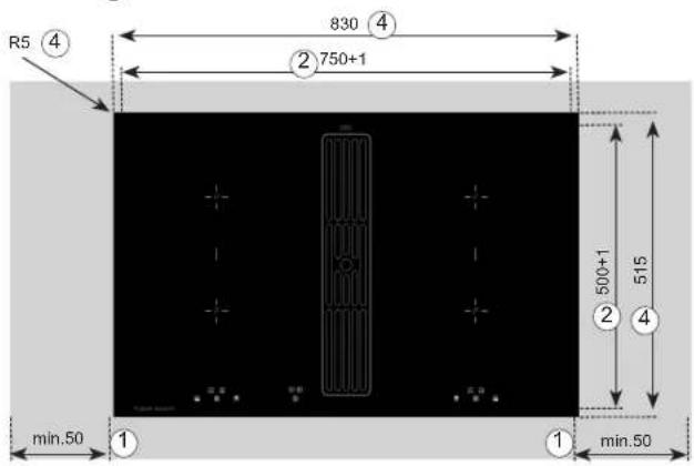
Insert the hob and align it.
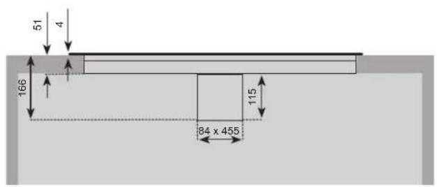
① Minimum clearance to adjacent walls
② Cut-out dimension
③ Recess dimension
④ Outer dimensions of hob
Flush installation
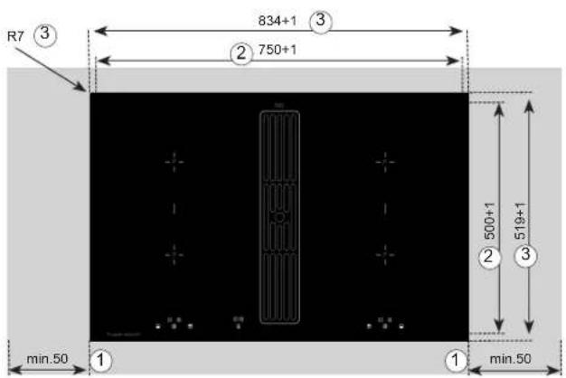
Glue the sealing tape onto the corner of the supporting edge of the worktop so that no silicone adhesive can be pressed under the hob. Place the hob into the worktop cut-out without any adhesive and align it. Use shims if necessary
Fill the gap between the hob and the worktop with heat-resistant silicone adhesive.
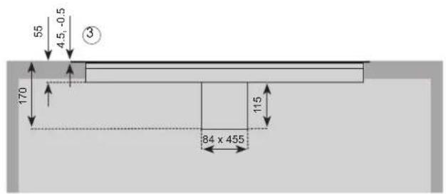
Important
Silicone adhesive must not get pressed anywhere under the supporting surface of the hob. If this occurs it will not be possible to remove the hob again at a later stage. No liability will be assumed in the case of failure to observe these instructions.
natural_image
Pure architectural line drawing of a modern office building (no text or symbols)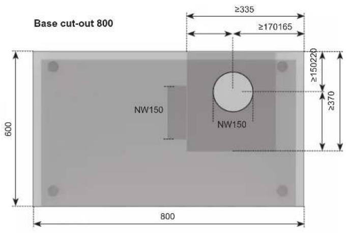
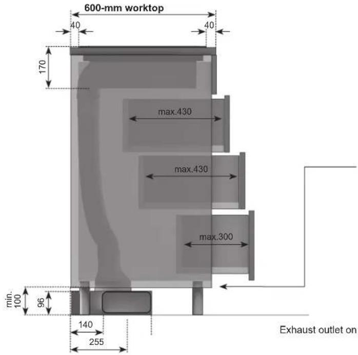
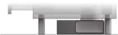
Option of outgoing air on the left or right:
Depending on installation, left or right can be chosen for outgoing air. Please note the dimensions shown opposite for optimal planning.
Exhaust outlet on the right

natural_image
Pure architectural or mechanical diagram showing a beam supported by two columns (no text or symbols)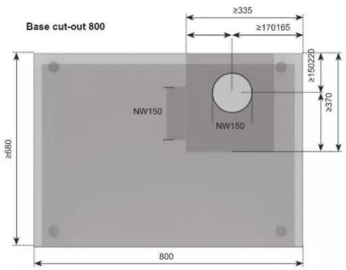
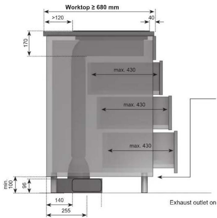
Option of outgoing air on the left or right:
Depending on installation, left or right can be chosen for outgoing air Please note the dimensions shown opposite for optimal planning.
Exhaust outlet on the right
Extraction air system assembly
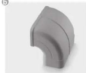
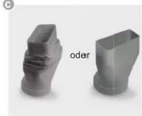
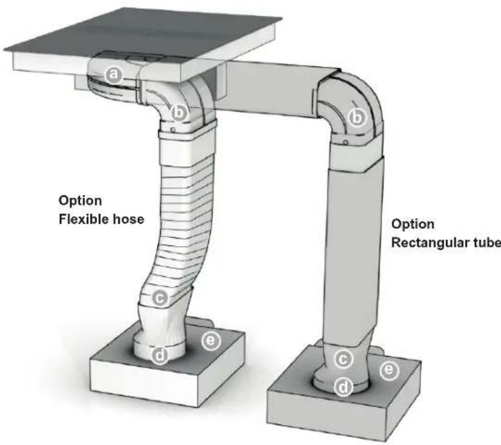
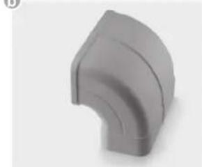
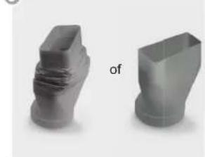
The hob and the fan can be connected with a fl exible hose or a fl at duct.
The exhaust air components for on these two options are supplied with the hob and are fitted into each other according to the illustration. Shorten the fl at duct with a fine saw if necessary.
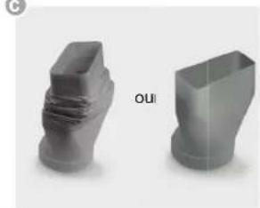
On point ©
The fl exible connection piece is used for a worktop thickness of 600mm . Please make sure that installation is as taut and crease-free as possible by shortening excess material.
On point
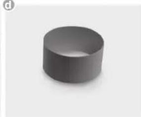
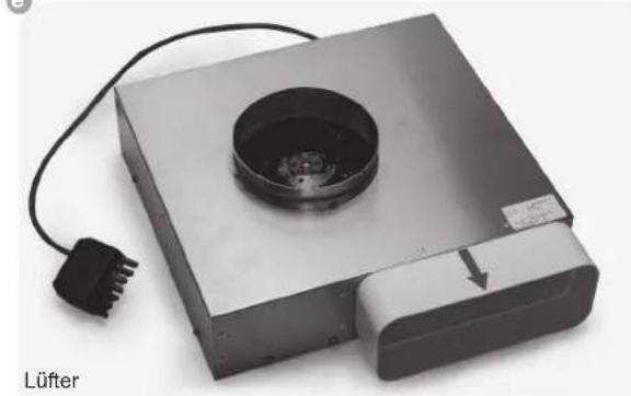
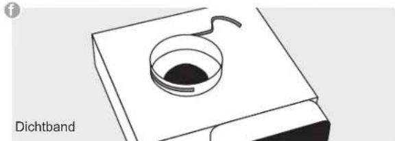
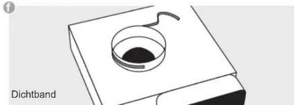
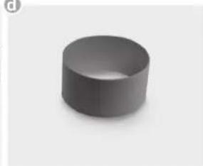
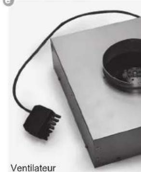
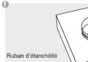
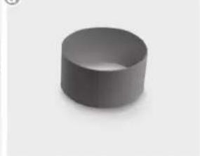
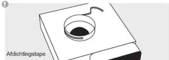
Apply sealing tape to the plinth fan connecting pieces (f) before attaching the adapter piece (d) to the plinth fan (e).
natural_image
Close-up of hands handling a white cylindrical object with a circular inset, no visible text or symbolsImportant:
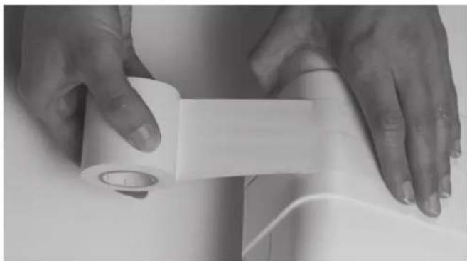
The components must all be firmly fastened as shown with the adhesive tape enclosed after they have been attached.
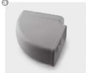
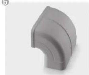
Exhaust air duct components (inclusive)
a
natural_image
Gray plastic object with curved edge, no visible text or symbols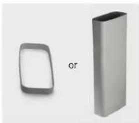
natural_image
Two metallic rectangular objects, one rounded and one solid, with the other partially visible (no text or symbols)b
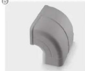
natural_image
3D rendered image of a gray curved pipe elbow joint (no text or symbols)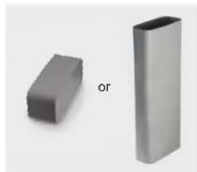
natural_image
Two gray 3D rectangular blocks, one labeled 'or', against a plain background (no text or symbols on the blocks themselves)©

natural_image
Two gray 3D mechanical parts, one with a folded top and the other a rectangular block, labeled 'or' (no text or symbols on the objects themselves)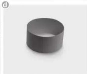
natural_image
3D rendered gray cylinder on white background (no text or symbols)e
natural_image
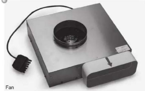
Exterior view of a metallic electronic device with a circular vent and power plug (no text or symbols visible)f
natural_image
Diagram of a Dichtband device with a circular component and curved arm, no text or symbols presentPlinth fi Iter (optional):
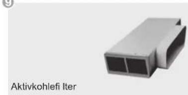
g
natural_image
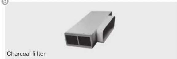
3D rendering of a gray rectangular electronic component with two internal slots, labeled 'Charcoal fi Iter' below (no other text or symbols)The fan plug connection must be made before the mains connection!
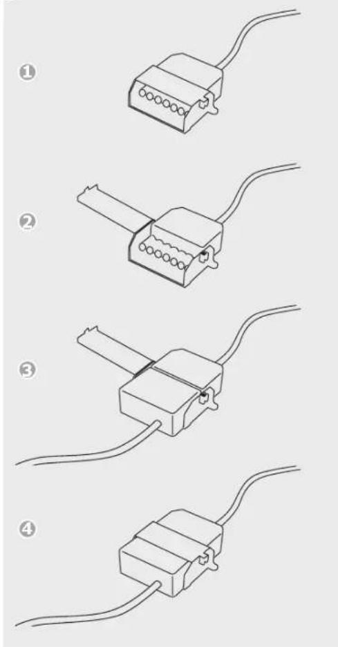
Connect the two 7-pole plus for the fan connection.
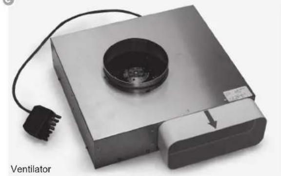
Open the plug retainer on the 7-pole plug (fan) of the hob and attach the 7-pole fan mating connector (e) until it is securely engaged. Then close the plug retainer again.
Attention
The appliance must be cut off from the electricity supply before the plug retainer is opened again. The appliance may only be connected to the mains once the plug connection has been made.
The hob may only be switched on when the fan mating connector has been attached and the plug retainer closed.
e
- The product may only be connected by a qualified fi tter according to applicable local regulations. The same applies for the extraction air connections. The fi tter is responsible for proper functioning at the installation site.
- On installation, observe the relevant national building regulations and the regulations of the electricity suppliers.
- The hob fan can be operated in the extraction air and recirculation air mode.
- Lead the outgoing air outside through a ventilation shaft intended for this purpose or through the wall of the building.
- Outgoing air may not be led into a smoke or exhaust gas flue which is in operation. Contact the district master chimney sweep if you are in any doubt.
- A suffi cient supply of inlet air must be provided if a wood, coal, gas or oil heater requiring a chimney is operated in the environment of the hob fan, since an insufficient supply of air results in a risk of poisoning. The safe operation of the hob fan is guaranteed when the negative pressure resulting from the hob fan does not exceed 0.04 mbar (4 Pa) and a sufficient supply of inlet air can flow into the room.
- Exhaust air pipes must comply with fire class B 1 DIN 4102. Please make sure that the minimum nominal width of the appliance connecting pieces is not reduced.
- The Naber Compair Flow 150 system recommended for the airflow and compatible with the hob extractor should always be used.
- The nominal width of the recirculation air pipe should not be less than 150 mm.
- Exhaust air pipes should be as short as possible. They should not have a 90-degree angle; instead they should have soft bends and no reductions in their cross-section.
- Never use pipes with a diameter of less than 150 mm. No bends/angles may be laid 50 cm before the fan module.
• Always insert a straight piece of approx. 50 cm between two angles/bends. - The cross-section of wall vents and the cut-out in the base panel should should at least correspond to the exhaust air pipe. The outflow opening must be at least 500 cm ^2 . Reduce the height of the skirting boards or make corresponding openings.
- When installing the appliance make sure that the convection air unit is still accessible when the kitchen has been completely installed. If necessary levelling feet for the kitchen units must be moved.
Important
For recirculation operation, sufficient ventilation has to be provided to the room in order to remove the air humidity.
Electrical connection
- The electrical connection must be carried out by a qualified electrician who is authorised to carry out such work!
• Statutory regulations and the connection specifications issued by the local power supply company must be observed. - When connecting the appliance it must be ensured that there is a device which makes it possible to universally disconnect it from the mains with a contact opening width of at least 3mm. Line-protecting switches, fuses or contactors are suitable cut-out devices. When connecting and repairing the appliance disconnect it from the electricity supply with one of these devices.
- The earth wire must be sufficiently long so that if the strain relief fails, the live wires of the connecting cable are subjected to tension before the earth wire.
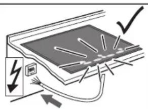
- Any superfluous cable must be removed from the installation area beneath the appliance.
- Make sure that the local mains voltage is the same as the voltage on the rating label.
- Full protection against accidental contact must be ensured on installation.
- Attention: Incorrect connection may result in the power electronics unit being destroyed.
Power supply
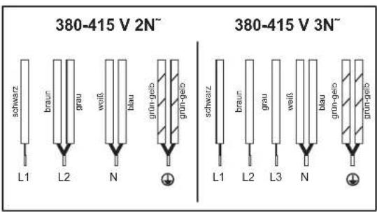
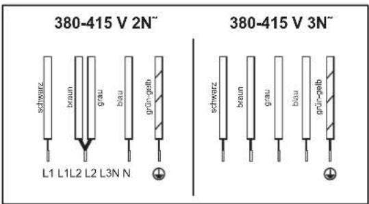
Mains voltage: 380-415V 3N\~, 50/60Hz
Component rated voltage: 220-240V
Mains cable available in the factory
- The hob has been fitted with a temperature-resistant connection cable in the factory.
- Connection to the mains is carried out in accordance with the circuit diagram, unless the connection cable is already fitted with a plug.
- If the mains supply cable of this appliance is damaged, it has to be replaced by the manufacturer, the Customer Service of the manufacturer or by another qualified person to avoid danger.
Electrical connections

Technical Data
Hob dimensions
Height/ Width/ Depth _mm
170 × 830 × 515
natural_image
Pure diagram of a vertical cylindrical object with plus and minus signs, no text or symbols presentCooking zones
front left cm / kW
back left cm / kW
back right cm / kW
front right cm / kW
Bridging function_cm/kW
19 x 21 / 1.6 (1.85)*
19 x 21 / 2.1 (3.00)*
19 × 21 / 1.6 (1.85)*
19 × 21 / 2.1 (3.00)*
39 x 21 / 3.7
Hob kW
Fan kW
Plasma kW
7.4
0.115
0.01
* Power when the power boost function is activated
Initial operation
Once the hob has been installed and the power supply has been provided (mains connected) an automatic test of the controls will be carried out and information for Customer Service will be indicated.
Important
No items may be on the touch control sensor keys when the appliance is being connected!
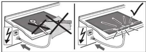
Briefly wipe over the surface of the hob with a sponge and soapy water and then dry with a clean cloth.


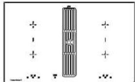
Module (Powermanagement)
Powermanagement
natural_image
Hand holding a tool near a sheet of paper with visible lines (no text or symbols)natural_image
Pure technical diagram of a mechanical or electrical component with directional arrows, no text or symbols present.Montage
Important
natural_image
Diagram of a curved structural component with an arrow indicating direction (no text or symbols)natural_image
Pure architectural line drawing of a modern office building (no text or symbols)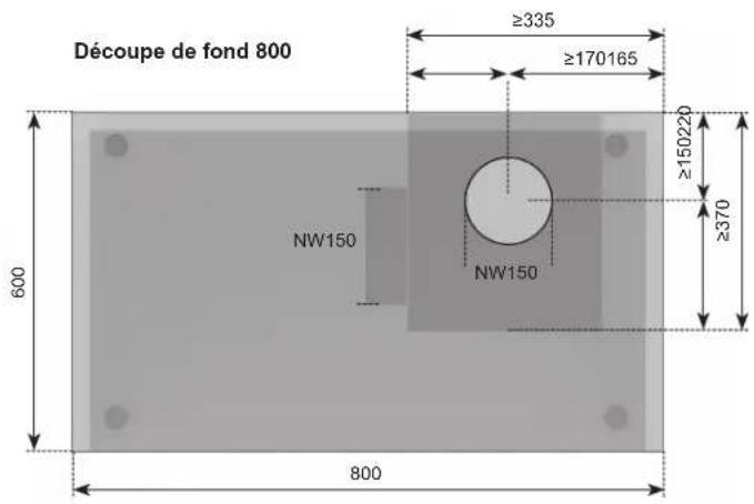
natural_image
Pure architectural or mechanical diagram showing a beam supported by two columns (no text or symbols)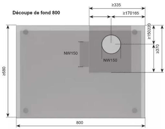
natural_image
Close-up of hands handling a white plastic roller or tape on a surface (no text or symbols visible)natural_image
Gray plastic object with a curved top and side gap, no visible text or symbols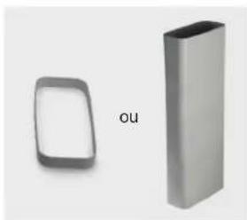
natural_image
Two metallic 3D geometric shapes, one rounded and one rectangular, with no text or symbols visible.b
natural_image
3D rendered image of a gray curved pipe elbow joint (no text or symbols)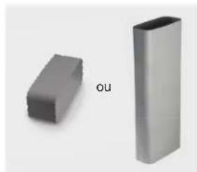
natural_image
Two gray 3D rectangular blocks, one labeled 'OU', against a plain background (no text or symbols on the blocks themselves)©
natural_image
Two gray 3D-printed mechanical components with no visible text or symbolsd
natural_image
3D rendered image of a gray cylindrical object with no text or symbolse
natural_image
Close-up of a portable electronic device with a black connector and a circular component, labeled 'Ventilateur' (no other text or symbols visible)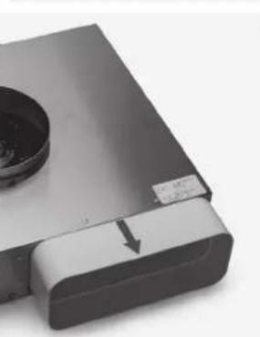
natural_image
Close-up of a silver electronic device with a circular lens and a rectangular base, showing a white object with an arrow pointing to it (no visible text or symbols)f
natural_image
Simple line drawing of a mechanical component with a circular opening and curved edge (no text or symbols)natural_image
3D rendering of a gray rectangular mechanical component with internal channels (no text or symbols)Zones de cuisson
ER03____ foutmelding
natural_image
Simple line drawing of a mechanical component with a downward arrow indicating force or motion (no text or symbols)Belangrijk



Modules (powermanagement)
Powerstand P
natural_image
Hand holding a pen writing on paper with grid lines (no text or symbols visible)natural_image
Diagram of a cabinet or storage unit with directional arrows indicating movement (no text or symbols)Montage
Belangrijk
natural_image
Diagram of a curved structural component with an arrow indicating direction (no text or symbols)natural_image
Pure architectural line drawing of a modern office or furniture structure without any text, numbers, or symbols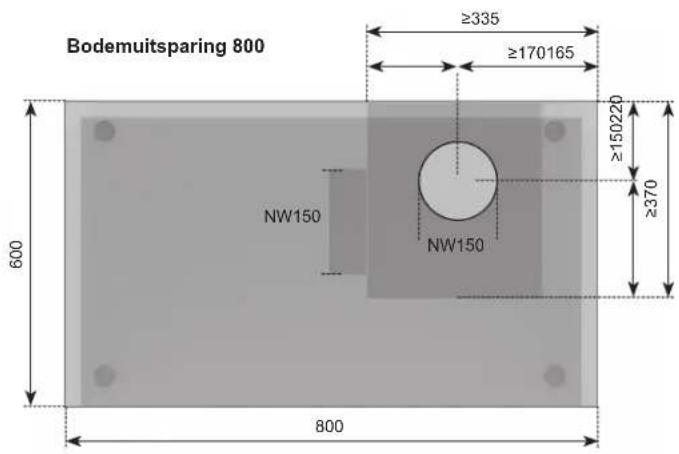
natural_image
Pure architectural line drawing of a modern building facade with no text or symbols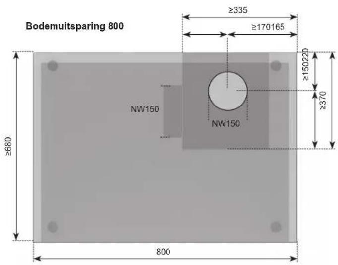
natural_image
Close-up of hands handling a white plastic roller or tape, no visible text or symbolsBelangrijk:
natural_image
Close-up of a gray plastic clip or connector (no text or symbols visible)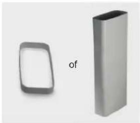
natural_image
Two metallic rectangular shapes, one rounded and one solid, with no text or symbols visible.b
natural_image
3D rendered image of a gray curved pipe elbow joint (no text or symbols)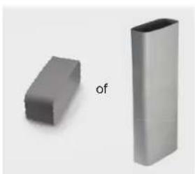
natural_image
Two gray 3D rectangular blocks, one labeled 'of', against a plain background (no text or symbols on the blocks themselves)©
natural_image
Two gray 3D-printed mechanical parts, one with layered structure and the other with stepped form (no text or symbols)d
natural_image
3D-rendered gray cylindrical object with smooth surface and no visible text or symbolse
natural_image
Exterior view of a portable electronic device with a circular vent and power plug (no text or symbols visible)f
Plintfi Iter (optioneel):
9

Technische gegevens
19 × 21 / 1,6 (1,85)*
19 x 21 / 2,1 (3,00) ^*
19 × 21 / 1,6 (1,85)*
19 × 21 / 2,1 (3,00)*
39×21/3,7
7.4
0,115
0,01

- Wichtig
- Kindersicherung L
- Powerstufe P
- Einbau
- Technische Daten
- Kochzonen
- Disposing of the packaging
- Disposing of old appliances
- Appropriate use
- For your information...
- Contents
- For connection and operation
- For the hob
- For persons
- Operating the hob with the sensor keys
- Standby key 3)
- ON/OFF key ☐7) Cooking zones left or right
- Cooking zone selection key; e.g. front ☐(3)
- Minus key ☐ Plus key (10)
- Power setting indicator (1)
- Minus key /Plus key Ventilation (14)
- The hob
- Advantages of the induction hob
- Pan recognition U
- Pan recognition limits
- Operation time limit
- Other functions
- Protection against overheating (induction)
- Cookware for induction hobs
- This is how to establish the suitability of a pot:
- Magnet test
- Important
- How to cut power consumption
- Power settings
- Residual heat indicator
- Switching the appliance into the standby mode
- Operating the keys
- Switching on the hob and cooking zones
- Switching off a cooking zone
- Switching off the hob
- Childproof lock L
- Switching on the childproof lock
- Switching off the childproof lock
- De-activating the childproof lock for one cooking procedure only
- Automatic switch-off (timer) Ⓤ
- Minute minder (egg timer)
- The cooking zones are switched off.
- Power boost P
- Power management
- Bridging function
- Using the fan
- Switching the fan on and off
- Hint
- Fan time lag
- Stop delay time
- Glass ceramic hob
- Cleaning after use
- Weekly cleaning
- Specific soiling
- Hob fan
- Cleaning the metal grease filters
- Do not operate the fan without grease filters!
- Fan cleaning and care
- Service
- The fuses blow regularly?
- You can't switch your induction hob on?
- The symbol rj will blink and a time-limited continuous signal will sound.
- Error code E2 is indicated?
- Error code E8 is indicated?
- Error code U400 is indicated?
- An error code (ERxx or Ex) is indicated?
- The pot sign appears U ?
- The pot sign still appears, even though a pot or pan was placed on the hob?
- Is the cookware you are using making noises?
- Does the cooling fan still operate after it has been switched off?
- Is the hob making noises (clicking or cracking sounds)?
- Does the hob have tears or cracks?
- Safety instructions for kitchen unit fitters
- Ventilation
- Installation
- Sealing of the hob
- Worktop cut-out
- Variable installation possibilities:
- Extraction air system assembly
- Attention
- Electrical connection
- Power supply
- Mains cable available in the factory
- Technical Data
- Initial operation
- Powermanagement
- Montage
- Zones de cuisson
- Belangrijk
- Powerstand P
- Technische gegevens
Brand : Küppersbusch
Model : KMI8500.0WR
Category : Cooker