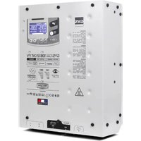
Gysflash 108.12 CNT FV - Welding machine GYS - Free user manual and instructions
Find the device manual for free Gysflash 108.12 CNT FV GYS in PDF.


User questions about Gysflash 108.12 CNT FV GYS
0 question about this device. Answer the ones you know or ask your own.
Ask a new question about this device
Download the instructions for your Welding machine in PDF format for free! Find your manual Gysflash 108.12 CNT FV - GYS and take your electronic device back in hand. On this page are published all the documents necessary for the use of your device. Gysflash 108.12 CNT FV by GYS.
USER MANUAL Gysflash 108.12 CNT FV GYS
natural_image
Technical line drawing of a rectangular enclosure with circular holes and a central display panel (no text or symbols)GYSFLASH

2-21 / 62-72

22-41 / 62-72

42-61 / 62-72
108.12 CNT FV
148.12 CNT FV
158.12 CNT FV
INSTRUCTIONS DE SÉCURITÉ

text_image
Auto - Detect 12.5v Charge 3sFoncton «Manual start»
text_image
Gestion code Code 1 -2-3-4 Auto-select Charge SupplyMISE EN ROUTE
text_image
Auto-select Start
text_image
Auto-select aucun contacttext_image
① Power-up 12 V n°01 ②1- Mode
2- Tension nominale
text_image
Power-up 14.0V 113A 00:00:25 5.8 Ah ① ② ④ ③ ⑤text_image
Icon set with magnifying glass and document symbol, likely representing search or editing functionstext_image
Calibration cables X Ytext_image
Mode Auto-select Charge Supply n°001 Power-up n°01 Dernier modetext_image
Gestion code Code 1 -2-3-4 Auto-select Charge Supply Power-uptext_image
Icon set with document, download, and upload symbols arranged in a grid on black backgroundThis manual contains safety and operating instructions. Please read it carefully before using the device for the first time and keep it for future reference. This machine should only be used for charging or power supply operations specified within the limits indicated on the machine and in the instruction manual. The operator must observe the safety precautions. In case of improper or unsafe use, the manufacturer cannot be held liable.
This unit can be used by children aged 8 or over and by people with reduced physical, sensory or mental capabilities or lack of experience or knowledge, if they are properly monitored or if instructions for using the equipment have safely been read and potential risks understood. Children must not play with the product. Cleaning and maintenance should not be performed by an unsupervised child.
Do not use to charge domestic batteries or non rechargeable batteries.
Do not use the charger if the mains cable or plug is damaged.
Never use on a frozen or damaged battery.
Do not cover the device.
Do not place the unit near a heat source or expose to prolonged high temperatures (above 60^ C).
The operating mode of the automatic charger and the restrictions applicable to its use are explained later in this manual.
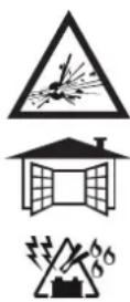
Fire and explosion risks!
- A battery can emit explosive gases when on charge.
- During the charge, the battery must be placed in a well ventilated area.
- Avoid flames and sparks.
- Protect the electrical contact surfaces of the battery against short circuits.
Do not leave a charging battery unattended for a long time.


Risk of acid dispersion!
- Wear protective goggles and gloves.
- In case of contact with the eyes or the skin, rinse immediately with water and see a medical doctor as soon as possible.
Connection / disconnection :
- Disconnect the power supply before plugging or unplugging the connections to/from the battery.
- Always ensure the Red clamp is connected to the «+» battery terminal first. If it is necessary to connect the black clamp to the vehicle chassis, make sure it is a safe distance from the battery and the fuel line. The charger must be connected to the mains.
- After charging, disconnect the charger from the mains, then disconnect the negative clamp from the car body and then disconnect the positive clamp from the battery, in this order.

Connection :
- The charger must be connected to an earthed power supply.
- This hardware is compliant with the IEC 61000-3-12, provided that the short-circuit power Ssc is greater than or equal to 2147242 at the interface point between the user's power supply and the public power supply network. It is the responsibility of the installer or user of the equipment to ensure, if necessary by consulting the operator of the public power supply network, that the equipment is solely connected to a power supply with a Ssc short-circuit power greater than or equal to 2147242.

Maintenance :
- If the power supply cable is damaged, the replacement cable must be obtained from the manufacturer or its service team.
- Maintenance should only be carried out by a qualified person.
- Warning! Always disconnect from the mains before performing maintenance on the device.
- If the internal fuse is melted, it must be replaced by the manufacturer (GYS dedicated sales service) or by an equally qualified person to prevent any accidents.
- Do not use solvents or any agressive cleaning products.
- Clean the device's surfaces with a soft, dry cloth.
C ∈
EAC UK CA

Regulations :
• The Machine is compliant with European directives.
- The declaration of conformity is available on our website.
• EAEC Conformity marking (Eurasian Economic Community).
- Equipment in compliance with British requirements. The British Declaration of Conformity is available on our website (see home page).
• Equipment in conformity with Moroccan standards.
- The declaration C_ (CMIM) of conformity is available on our website (see cover page).

Waste management:
- This product should be disposed of at an appropriate recycling facility. Do not throw away in a household bin.
GENERAL DESCRIPTION
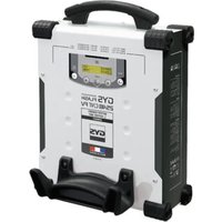
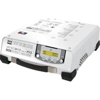
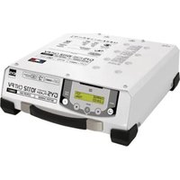
Your Gysflash is a high-power, multifunctional, professional power supply. It features inverter technology designed to provide energy support for low-voltage industrial systems, such as automotive production lines. It also provides optimal charging performance for maintaining the most advanced batteries. This device can accommodate output cables of up to 8 m. Changing the output cables requires recalibration (see page 27). It is considered a fixed device, not a mobile one.
As standard, your Gysflash is supplied with a configuration consisting of 4 modes:
- Charge Mode: dedicated to recharging lead (sealed, Liquid, AGM...) or lithium (LiFePO4) starter batteries.
- Supply mode (eg: EPS): a power supply to meet the power requirements of a system (example: motor vehicles)
- Auto-Select mode: automatically selects the correct mode depending on what is connected to the Gysflash output.
- Power-up mode: reactivates a lithium battery in UVP (Under Voltage Protection) state.
Your GYSFLASH is SMART!
The built-in functionality of your Gysflash can be extended by adding specific charging modes and profiles via USB communication, and custom configurations.
Your Gysflash also offers the facility to retrieve data from hundreds of charges onto your USB stick, for analysis in a spreadsheet. Additional modules (such as printers, Ethernet communication, CAN Open, TOR, etc.) can also be attached via the dedicated module sockets.
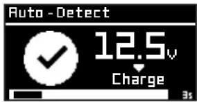
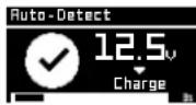
«Auto-Detect» function:
The Gysflash is equipped with the «Auto-Detect» function, which automatically starts a charge when a contact is detected at the output of the Gysflash. (To activate/deactivate this function, see page 29)
text_image
Auto - Detect 12.5v Charge 3s«Manual start» function:
The «Manual start» function allows manual start to be authorised or not by pressing the START/STOP button.

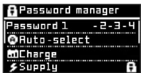
It is possible to lock modes with a «user» password, and also define the value of this password. All the modes marked with a padlock have access restricted by a «user» password (to set the lock, see page 29).
text_image
Password manager Password 1 -2-3-4 Auto-select Charge SupplySTART UP
- Connect the Gysflash to the mains socket.
- Set the switch to «ON».
- Select the operating mode you require (Auto-Select -> Charge -> EPS -> Power-up).
To access the Configuration Menu, press the Edition.

MENU NAVIGATION AND MODE SETTINGS
| 1 Use the arrows to move around the menu or to change the value or condition of a parameter. |   |
| 2 Press the SELECT button to enter a sub-menu, select a parameter, or confirm a parameter value. |  |
| 3 Press the back button to return to the previous menu (or sub-menu). |  |
CHARGE MODE
text_image
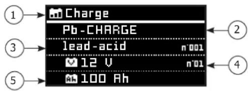
Charge Pb-CHARGE lead-acid n001 12 V n01 100 Ah1 - Mode
2 - Charging group
3 - Charging curve
4 - Nominal battery voltage
5 - Nominal battery capacity (curve permitting)
| Profile Charging voltage Maintenance voltage | ||
| Lead-acid | 2.47 V/cell 2.2 V/cell Lead batteries. | |
| Lithium | 3.50 V/cell 3.45 V/cell Lithium batteries (LiFePO4) | |
Starting the charge:
Manual start
To start the charge, press the START/STOP button.
1 Automatic start-up
If the AUTO-DETECT function is active, charging will start automatically after 3 seconds if a battery is present.
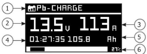
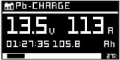
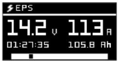
2 During charging, your GYSFLASH will indicate the percentage of progress of the charging cycle, voltage, current, amp-hours delivered, and time elapsed.
3 Press the START/STOP button to stop the charge.


text_image
13.5 u 113 A 01:27:35 105.8 Ah 27:241- Applied charging curve
2- Battery voltage
3- Current supplied by the charger
4- Elapsed time
5- Amp-hours delivered
6- Charge cycle progress
Precautions:
When charging a vehicle, it is advisable to reduce the vehicle's power consumption to a minimum (turn off the lights, switch off the ignition, close the doors, etc.) so as not to disrupt the charging process.
Precaution: Check the electrolyte level for open batteries. If necessary, adjust levels before charging.
SUPPLY MODE
text_image
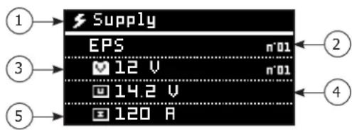
Supply EPS n°01 12 V n°01 14.2 V 120 A1- Mode
2- Cycle Supply
3- Nominal voltage (mode permitting)
4- Supply voltage
5- Supply current
| Mode | «Contact detection» function | «Battery detection» function | «Integrated charge» function | Abnormal undervoltage protection | Adjustment of the voltage to be regulated | Adjustment of the maximum current |
| EPS | √ | √ | 14.2 V 150 A |
If this function is available, the Gysflash automatically detects the presence of an output contact (for example: vehicle with or without battery) and starts to supply power. In this situation, a contact must be present for the mode to work.
- «Battery detection» function
If this function is available, the Gysflash automatically detects the presence of a battery and starts to supply power. In this situation, a battery is required for the mode to work.
- «Integrated charge» function
If this function is available, the supply mode incorporates an automatic charging algorithm adapted to all types of battery (lead and lithium), to ensure that the battery is charged to the optimum level.. This function is still fully compatible when consumers are present on the battery.
• Abnormal undervoltage protection
If the function is available, this feature prevents the risk of short-circuiting or damaging the battery. The unit will stop automatically if the voltage is abnormally low.
- Starting the power supply:
| 1 | Manual startTo start the supply mode, press the START/STOP button. |  |
| Automatic start-upIf the AUTO-DETECT function is active, power supply will start automatically after 3 seconds if a battery or contact is present on the Gysflash output (e.g.: vehicle without battery). | 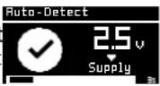 | |
| 2 | During supply mode, the Gysflash indicates the voltage, current, elapsed time and ampere-hours delivered. | |
| 3 | Press the START/STOP button to stop the charge. |  |
AUTO-SELECT MODE
This function automatically selects the mode and type of charge to be applied, depending on what is connected to the Gysflash output.
- Starting mode
To activate the mode, press the START/STOP button. Your Gysflash is now ready to detect whatever is connected to its output.
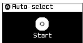
text_image
Auto-select Start
text_image
Auto-select no contactAuto-Select inactive Auto-Select active
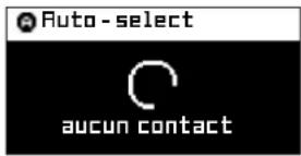
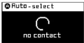
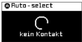
If no contact is detected at the output, the device does not supply any voltage and displays «no contact» on the screen.
- Case 1: Connecting to a battery
When the Gysflash detects the presence of a battery, it will run an algorithm for around 30 seconds to determine whether it is a lead or lithium battery. Once the identification has been made, it automatically switches to Charge mode with the appropriate profile (Lead or Lithium).
| 1 |  | Battery detection |
| 2 | 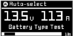 | Algorithm for determining the battery type |
| 3 | 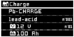 | Launching the appropriate charge |
 |
- Case 2: Connecting to a load
When the Gysflash detects the presence of a contact (e.g.: vehicle without a battery), it will automatically switch to EPS mode.
1
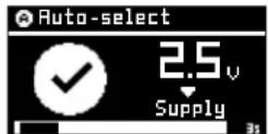
Contact detection (example: Vehicle without battery)
2
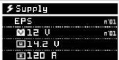
Launch the associated Supply mode (e.g.: EPS).
POWER UP MODE
text_image
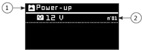
Power-up 12 V n'01 ① ②1- Mode
2- Nominal voltage
Starting the charge:
1 To start the mode, press the START/STOP button.
text_image
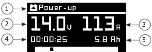
Power-up 14.0v 113A 00:00:25 5.8 Ah ① ② ④ ③ ⑤2
Your Gysflash will apply a voltage to the lithium battery under UVP protection to reactivate it.
If the battery is still not reactivated after a while, the charger stops and indicates an error.
3 When this process is complete, your Gyshash will automatically switch to CHARGE mode (Lithium) to finish charging the battery.
1- Current mode
2- Voltage supplied by the charger
3- Current supplied by the charger
4- Time remaining
5- Amp-hours delivered

Warning: reversing the polarity during use could damage the charger and the electronics in the vehicle.
PROTECTIONS
This device is protected against short-circuits and reverse polarity. It features an anti-spark system, which prevents any sparks when connecting to a battery. If there is no contact on the output, it does not deliver any current for safety reasons. This device is protected against operator error via an internal fuse.
CONFIGURATION MENU
The configuration menu can be accessed by pressing the button.

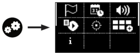
flowchart
graph LR
    A["Input Gear Icon"] --> B["Grid with icon legend"]
    B --> C["Output Grid with icon legend: flag, play button, speaker, plus, grid of icons"]

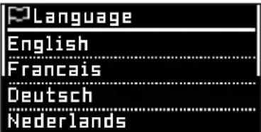
Language selection
text_image
Language English Francais Deutsch NederlandsSelection of the onscreen language, 19 different options are available.

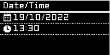
Date / Time
text_image
Date/Time 19/10/2022 13:30Option to set the date and time on the device.

Sound

The audio of the Gysflash and the external light module can be activated or deactivated.

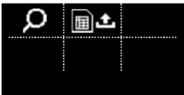
Traceability
text_image
Icon set with magnifying glass and document symbol, likely representing search or editing functionsYou can view or retrieve the last 1,000 historical charging records.


Explore Data Possibility of displaying the data collected over the last 1,000 loads on screen.
Export data (.csv)
The data collected from the last 1,000 charges can be exported to a USB stick in .CSV format.
| 1 Connect the USB stick to the Gysflash | |
| 2 Enter the «Export DATA» submenu. | |
| 3 Confirm that the charging data has been saved. | |
| 4 | The Gysflash will then copy the charging data to the USB stick in the form of a «.CSV» file. |

Cable calibration
Cable calibration
Automatic
Manual
Cables can be calibrated either automatically (recommended) or manually.
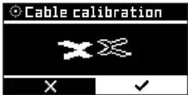
This procedure is used to calibrate the charging cables of the unit, so the Gysflash can effectively compensate for any voltage drop caused by the cables. We strongly recommend that you carry out this procedure every time you replace your cables, or if they are getting worn.
Automatic calibration (recommended)
text_image
Cable calibration X X Y X ✓To calibrate, simply short-circuit the charging clamps and then confirm. The device then automatically calculates the cable resistance.
text_image
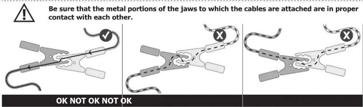
Be sure that the metal portions of the jaws to which the cables are attached are in proper contact with each other. OK NOT OK NOT OKManual calibration (not recommended)
text_image
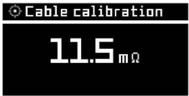
Cable calibration 11.5mΩThe cable resistance can be set manually. Warning: this value must include the internal resistance of the Gysflash.
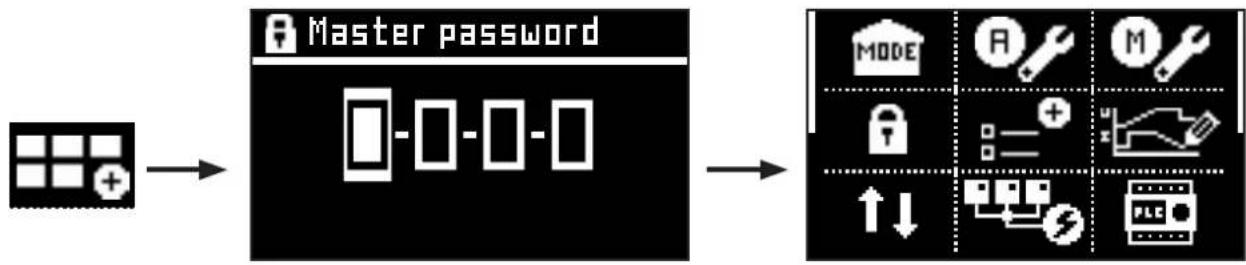
Advanced settings
This menu gives you access to the advanced features of your Gysflash. A Master password is required for access.
flowchart
graph LR
    A["Input Image"] --> B["Master password"]
    B --> C["MODE: R, M, Lock, Error Bars, PLC"]
Main mode
text_image
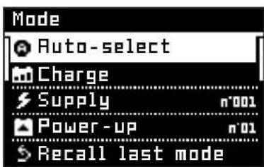
Mode Auto-select Charge Supply n°001 Power-up n°01 Recall last modeThis menu is used to set the main operating mode of the Gysflash. This is the mode that the device reverts to when it is switched on, at the end of a period of operation (battery disconnection, manual shutdown, fault reset, etc.), or when the Configuration menu is closed.
If «Recall last mode» is selected, the unit will always restart in the last mode used.
Auto Select menu
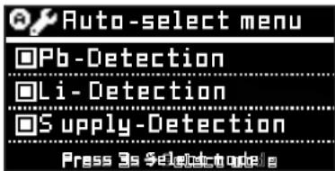
text_image
Auto-select menu □Pb-Detection □Li-Detection □Supply-Detection Press 3s Select to play
Activated Deactivated
This menu is used to set the different types of detection that are possible in the AUTO-SELECT mode, as well as the curves/modes to be launched with each type of detected signal.
The curve associated with each type of detection can be modified by pressing SELECT for 3 seconds.
If only one detection is activated between Pb-detection and Li-detection, the «Battery type test» routine is bypassed.
Manual access
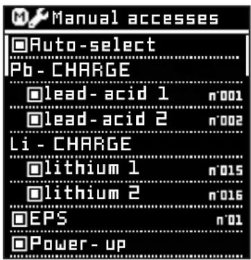
text_image
Manual accesses Auto-select Pb - CHARGE lead-acid 1 n'001 lead-acid 2 n'002 Li - CHARGE lithium 1 n'015 lithium 2 n'016 EPS n'01 Power-up
Activated Deactivated
This menu is used to define the modes that can be accessed manually. It contains a complete list of all the modes and curves available on the installed configuration. The modes that can be accessed manually are the ones that are selected on the list.
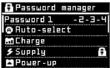
Password manager
text_image
Password manager Password 1 -2-3-4 Auto-select Charge Supply Power-upThis menu is used to specify which modes have restricted manual access by means of a «User» password, and is also used to enter the value of this password.
All modes marked with a padlock have restricted access by means of the «User» password.
+ Options
text_image
+Options □Manual Start □Auto-Detect □Auto-Restart
Activated Deactivated
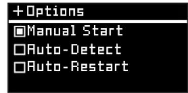
This menu is used to select whether or not to activate the Auto-Detect and Auto-Restart functions.
Manual start option: This function allows you to authorise or disable the start of a mode by pressing the START/STOP button.
Auto-detect function: With this function, the Gysflash automatically initiates a charge when contact is detected on the output. If this option («Auto-detect») is disabled, a contact on the output will only be detected using the «Auto-select» mode, and all other modes can only be initiated by a manual START.
Auto-restart option: This function allows the Gysflash to restart automatically in the event of a power cut.
CONFIG Designer
This menu is used to modify the advanced settings for each mode and/or charge curve.
| Mode Parameter Description | ||
| System T_ | esv Delay time between initiation and the start of the charge | |
| Charge U_ | esp Minimum voltage to authorise the start of the charge | |
| U_lade Charging voltage | ||
| I_lade Charging current | ||
| I_ehl | Current threshold beneath which the charger will switch to trickle charging (floating) | |
| T_min Minimum charge duration before switching to trickle charge (floating) | ||
| T_max Maximum duration authorised for charging step | ||
| Q_max Maximum authorised charge capacity | ||
| T/Q_max error Charger behaviour in the event of a T_max or Q_max error:- EHL : a maintenance charge is applied- OFF: charger shutdown | ||
| U_ehl Maintenance voltage (floating) | ||
| T_ges Maximum time allowed for the complete charge cycle | ||
| U_low Minimum voltage allowed during charging | ||
| EPS Detect | Choosing the type of detection:- Load: detection of contact on the output (example: vehicle with or without battery)- Bat: battery detection- Bat (+Force 3s) : Battery detection, with the ability to force-start without a battery by holding down the START button for 3 seconds- Manual: No detection, manual start only | |
| U_eps Power supply voltage | ||
| I_eps Maximum current | ||
| U_low | Minimum voltage allowed during power supply | |
| T_max Maximum authorized operating duration | ||
| Power-up | U_bat_err | Maximum voltage allowed to start Power-Up mode |
| U_reakt | Reactivation and pre-charge voltage | |
| I_reakt | Reactivation and pre-charge current | |
| T_reakt Duration of reactivation period | ||
| I_reakt_err | Minimum current required at the end of reactivation in order to consider the battery reactivated, and move on to the next stage. | |
| T_lade | Duration of lithium battery precharge stage after reactivation | |
| U_verif Minimum voltage required to consider a battery successfully reactivated during the test phase | ||
| T_verif Duration of lithium battery test stage | ||
| U_low Minimum voltage allowed during reactivation and precharging | ||
Portability
text_image
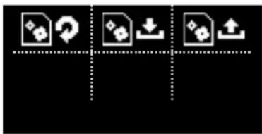
Icon set with document, download, and upload symbols arranged in a grid on black backgroundThis menu is used to import, export, or initialize configurations for the gysflash.

Restore CONFIG
This operation restores the original (factory) configuration of the Gysflash following any manual changes to modes or parameters.
1 Enter «Restore CONFIG» submenu.
2 Confirm the restoration of the configuration.
3 The Gysflash will then be restored to its original (factory) configuration.

Import CONFIG (.gfc)
This action downloads a complete new factory configuration to the Gysflash. The current configuration is then overwritten.
| 1 | First, make sure that the».gfc» file corresponding to the new configuration is present on the USB stick. This file must not be located in a folder or subfolder of the USB stick. |
| 2 Plug the USB stick into the Gysflash. | |
| 3 Enter the «Import CONFIG» submenu. | |
| 4 Select the relevant file to install. | |
| 5 Confirm file installation. | |
| 6 The Gysflash will then install the new configuration. | |
Export CONFIG (.gfc)
This action downloads the current Gysflash configuration to a USB stick.
1 Plug the USB stick into the Gysflash.
2 Enter the «Export CONFIG» submenu.
3 Confirm that the configuration has been saved.
4 The Gysflash will then save the current configuration to the USB stick.

Multi-chargers
text_image
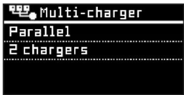
Multi-charger Parallel 2 chargersThis menu is used to configure the Multi-charger mode (see page 36 for details). Select «Single» for normal use with a single Gysflash.

Remote control
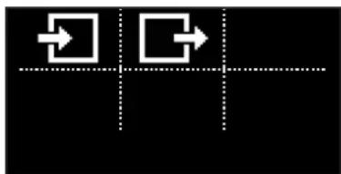
flowchart
graph TD
    A["Start"] --> B{Condition}
    B --> C["Process"]
    C --> D["End"]
This menu is dedicated to configuring remote control of the Gysflash via the auxiliary connector ③ (see page 35 for more details on auxiliary connectivity).
Input Menu
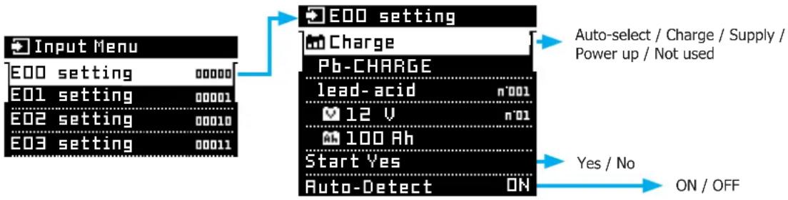
This menu is used to define the modes assigned to each of the 32 possible auxiliary connectivity input states (see page 35 for more details on auxiliary connectivity).
flowchart
graph TD
    A["Input Menu"] --> B["E00 setting"]
    A --> C["E01 setting"]
    A --> D["E02 setting"]
    A --> E["E03 setting"]
    B --> F["E00 setting"]
    C --> G["Charge"]
    C --> H["Pb-CHARGE"]
    C --> I["lead-acid n'001"]
    C --> J["12 V n'01"]
    C --> K["100 Ah"]
    D --> L["Start Yes"]
    D --> M["Auto-Detect ON"]
    F --> N["Auto-select / Charge / Supply / Power up / Not used"]
    G --> O["Yes / No"]
    H --> P["ON / OFF"]
    I --> Q["ON / OFF"]
    J --> R["ON / OFF"]
    K --> S["ON / OFF"]
For each input state, it is possible to define:
- The mode to be assigned (Auto-select / Charge / Supply / Power-up / Not used). If an input status is set to «Not used», no mode will be assigned to it, and the status will remain unaffected.
- The settings of the mode to be affected (charging curve, nominal voltage, capacity, etc.).
- The Start option: If this option is enabled (Yes), the Gysflash simulates a START press when the corresponding input state is applied.
- Auto-Detect option: This option enables or disables the Auto-Detect function when the corresponding input status is applied (see page 29 for more details on the Auto-Detect function).

Output Menu
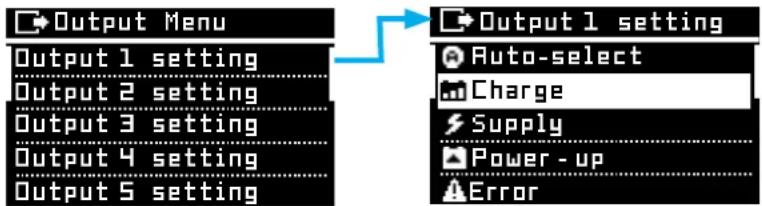
This menu is used to define the behavior of each of the 5 auxiliary connector outputs (see page 35 for details on auxiliary connectivity).
flowchart
graph LR
    A["Output Menu"] --> B["Output 1 setting"]
    A --> C["Output 2 setting"]
    A --> D["Output 3 setting"]
    A --> E["Output 4 setting"]
    A --> F["Output 5 setting"]
    B --> G["Output 1 setting"]
    G --> H["Auto-select"]
    G --> I["Charge"]
    G --> J["Supply"]
    G --> K["Power-up"]
    G --> L["Error"]
For each auxiliary connector output, you can check the Gysflash states in which the output must be active (dry contact closed).
| Auto-select | ☐ Stop - standby | Auto-select in standby | |
| ☐ Stop - start enable | Auto-select inactive | ||
| ☐ Ready | Auto-select ready to detect a contact | ||
| ☐ Contact | Auto-select with contact detected | ||
| ☐ Battery type test | Auto-select with battery type detection running | ||
| Charge Group selection | ☐ Group 0 | Charge group list | |
| ☐ Group 1 | |||
| ... | |||
| Status | ☐ Stop - standby | ||
| ☐ Stop - start enable | |||
| ☐ Stop - detect ready | |||
| ☐ Stop - detect + start | |||
| ☐ Stop - contact | |||
| ☐ Run - in progress | |||
| ☐ Run - charge OK | |||
| Supply Supply selection | □ Supply 0 | Supply mode list | |
| □ Supply 1 | |||
| ... | |||
| Status | □ Stop - standby | Supply inactive with Autodetect OFF and Manual Start OFF (no start possible) | |
| □ Stop - start enable | Supply inactive with Autodetect OFF and Manual Start ON | ||
| □ Stop - detect ready | Supply inactive with Autodetect ON and Manual Start OFF | ||
| □ Stop - detect + start | Supply inactive with Autodetect ON and Manual Start ON | ||
| □ Stop - contact | Supply inactive with contact detected | ||
| □ Run - NOK | Supply in progress with NOK output voltage | ||
| □ Run - OK | Supply in progress with output voltage OK | ||
| Power up | □ Stop - standby | Power up inactive with Autodetect OFF and Manual Start OFF (no start possible) | |
| □ Stop - start enable | Supply inactive with Autodetect OFF and Manual Start ON | ||
| □ Run | Power-up in progress | ||
| Error | □ Device | Device error | |
| □ User | Operating error | ||
For Charge mode, the output is activated only if the group in use corresponds to a checked group (Group selection) and the charger status corresponds to one of the checked statuses (Status).
For Supply mode, the output is activated only if the mode in use corresponds to a checked Supply mode (Supply selection) and the charger status corresponds to one of the checked statuses (Status).
If none of the boxes is checked, the output never activates. Conversely, if all boxes are checked, the output is activated as soon as the charger is switched on.
i
Information

Information
GYSFLASH 158.12
HW 08.01-HMI 03.01
SW 01.00
22.11.069909.000000
This menu displays information about your Gysflash:
- Device name
- Hardware/software versions
- Serial number
Keyboard/Scanner
Keyboard/Scanner Menu
Type QWERTY
Identificaion
This menu lets you configure the type of keyboard or scanner connected to the loader (QWERTY, AZERTY, QWERTZ). It also gives you the option of enabling or disabling the identification function, which uses the keypad and/or barcode scanner to associate specific information with each charge, such as the customer's name, the vehicle model, the VIN number, the battery number and so on. This menu only appears if a barcode reader is connected to the charger.

To scan barcodes (or QR code instructions), it is advisable to deactivate the identification function.
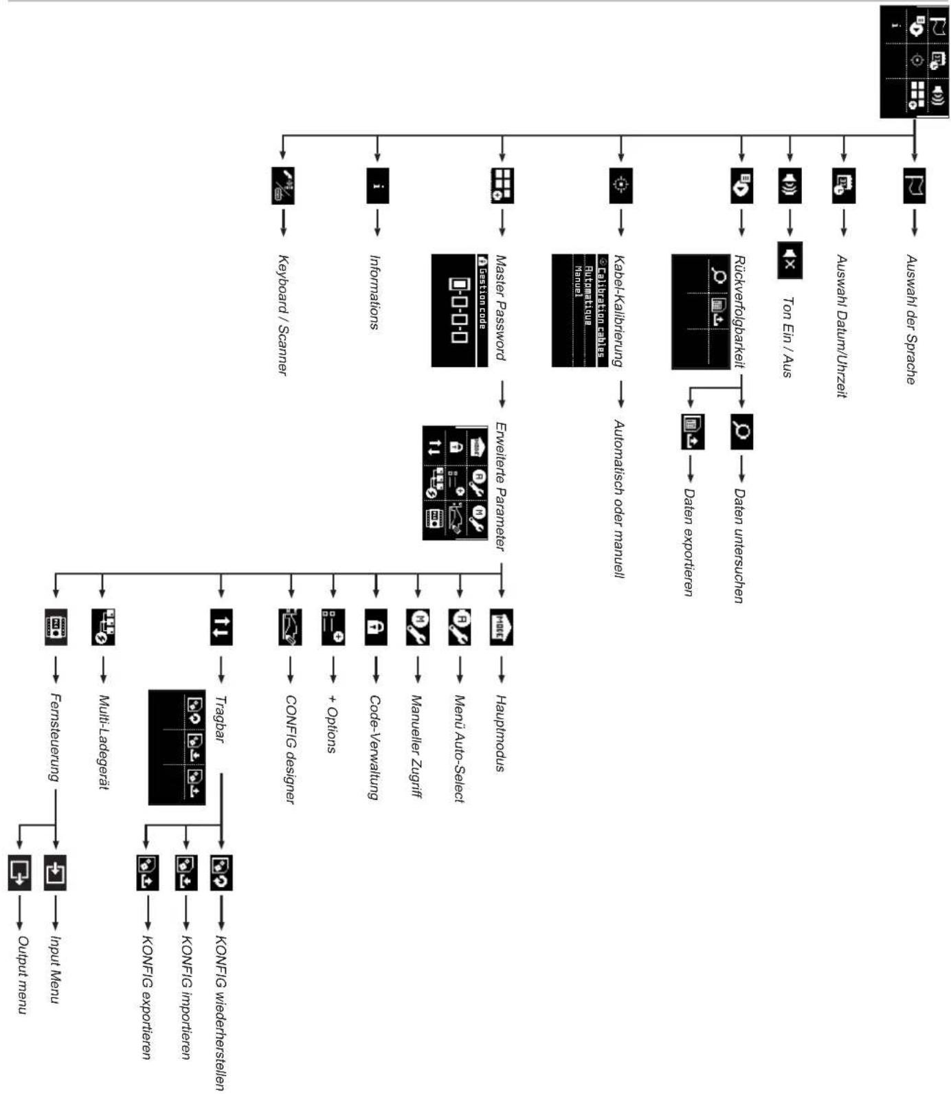
CONFIGURATION MENU STRUCTURE
flowchart
graph TD
    A["Input menu"] --> B["Fernsteuerung"]
    A --> C["Multi-Ladegerät"]
    A --> D["Tragbar"]
    A --> E["KONFIG wiederherstellen"]
    A --> F["Output menu"]
    B --> G["Fernsteuerung"]
    C --> H["Multi-Ladegerät"]
    D --> I["Tragbar"]
    E --> J["KONFIG importieren"]
    F --> K["Manueller Zugriff"]
    F --> L["Menu Auto-Select"]
    F --> M["Hauptmodus"]
    G --> N["Keyboard / Scanner"]
    H --> O["Informations"]
    I --> P["Master Password"]
    J --> Q["AutoMettique"]
    K --> R["Information Code"]
    L --> S["Autonomical oder manuell"]
    M --> T["Rückverfolgbarkeit"]
    T --> U["Daten exportieren"]
    U --> V["Daten untersuchen"]
    V --> W["Kabel-Kalibrierung"]
    W --> X["Automatisch oder manuell"]
    X --> Y["Information Code"]
    Z["Auswahl der Sprache"] --> AA["Auswahl Datum/Uhrzeit"]
    AA --> AB["Ton Ein / Aus"]
    AB --> AC["Information Code"]
    AD["Auswahl der Sprache"] --> AE["Auswahl Datum/Uhrzeit"]
CONNECTIVITY MODULES
Your GYSFLASH is equipped with an SMC socket, enabling you to connect various additional GYS modules, such as a printer, Ethernet interface, or others, to extend the capabilities of your device.
AUXILIARY CONNECTIVITY
Your Gysflash is fitted with an auxiliary connector for operating it remotely. 5 control inputs and 5 control outputs are available.
Connector Pinout
| MS-A series from Amphenol | ||
| Receptacle: MS 3102 S 22-19 | ||
| Plug: MS 3106 P 22-19 | ||
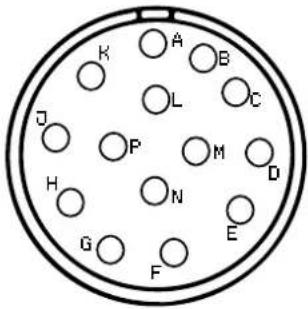 | Pin n° Description | |
| A Input 5 | ||
| B Input 4 | ||
| C Input 3 | ||
| D Input 2 | ||
| E Input 1 | ||
| F Output 5 | ||
| G Output 4 | ||
| H Output 3 | ||
| J Output 2 | ||
| K Output 1 | ||
| L COM | ||
| M CAN N | ||
| N GND | ||
| P CAN P | ||
Electrical characteristics
| Inputs Output | ||
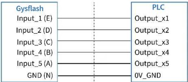 GND is the ground reference for inputs. When using PLC, this potential must be connected to 0V-GND. GND is the ground reference for inputs. When using PLC, this potential must be connected to 0V-GND. | ||
| Characteristics MIN MAX | ||
| Signal OFF "0" | -0.3 V | 2.0 V |
| Signal ON "1" | 3.0 V | 30.0 V |
| Input Impedance | 8kΩ | 15kΩ |
| Characteristics MIN MAX | ||
| Signal OFF "0" | -0.3 V | 2.0 V |
| Signal ON "1" | 3.0 V | 30.0 V |
| Input Impedance | 8kΩ | 15kΩ |
| Contacts Ratings | |
| Maximum Switching Power | 30W, 62.5VA |
| Maximum Switching Voltage | 60 VDC, 60 VAC |
| Maximum Switching Current | 1 A |
| Maximum Carrying Current | 2 A |
Control via the 5 auxiliary inputs:
The Gysflash can be controlled by acting on 5 inputs, enabling 32 input states from E00 to E31 to be defined.
| Auxiliary input truth table | ||||||
| Etats d'entréeE00* 0 0 0 | Input_5 (A)0 0 | Input_4 (B) | Input_3 (C) | Input_2 (D) | Input_1 (E) | Original Gysflash input configurationStatus not used |
| E01 0 0 0 0 | 1 | |||||
| E02 0 0 0 1 | 0 | |||||
| E03 0 0 0 1 | 1 | |||||
| E04 0 0 1 0 | 0 | |||||
| E05 0 0 1 0 | 1 | |||||
| E06 0 0 1 1 | 0 | |||||
| E07 0 0 1 1 | 1 | |||||
| E08 0 1 0 0 | 0 | |||||
| E09 0 1 0 0 | 1 | |||||
| E10 0 1 0 1 | 0 | |||||
| E11 0 1 0 1 | 1 | |||||
| E12 0 1 1 0 | 0 | |||||
| E13 0 1 1 0 | 1 | |||||
| E14 0 1 1 1 | 0 | |||||
| E15 0 1 1 1 | 1 | |||||
| E16 1 0 0 0 | 0 Auto-Select mode inactive | |||||
| E17 1 0 0 0 | 1 Auto-Select mode ready to detect | an output contact | ||||
| E18 | 1 | 0 | 0 | 1 | 0 | Lithium Charge mode inactive (Auto-Detect OFF) |
| E19 1 0 0 1 | 1 Charge Lithium mode ready to detect a battery | |||||
| E20 | 1 | 0 | 1 | 0 | 0 | Charge Lead mode inactive (Auto-Detect OFF) |
| E21 | 1 | 0 | 1 | 0 | 1 | Charge Lead mode ready to detect a battery |
| E22 | 1 | 0 | 1 | 1 | 0 | EPS mode inactive (Auto-Detect OFF) |
| E23 1 0 1 1 | 1 EPS mode ready to detect an output contact | |||||
| E24 1 1 0 0 | 0 Auto-Select mode inactive without Manual Start | |||||
| E25 1 1 0 0 | 1 Auto-Select mode ready to detect an output contact | without Manual Start | ||||
| E26 | 1 | 1 | 0 | 1 | 0 | Lithium Charge mode inactive (Auto-Detect OFF) without Manual Start |
| E27 1 1 0 1 | 1 Charge Lithium mode ready to detect a battery without | Manual Start | ||||
| E28 1 1 1 0 | 0 Charge Lead mode inactive (Auto-Detect OFF) without | Manual Start | ||||
| E29 1 1 1 0 | 1 Charge Lead mode ready to detect a battery without | Manual Start | ||||
| E30 1 1 1 1 | 0 EPS mode inactive (Auto-Detect OFF) without Manual | Start | ||||
| E31 1 1 1 1 | 1 EPS mode ready to detect an output contact without | Manual Start | ||||
For each input state, a mode (and its setting) can be assigned (see page 32 for details of input state mode assignment).
When the input state changes, the Gysflash stops the mode in use, starts the mode corresponding to the new input state, then applies the various associated options (Start, Auto-Detect...).
For a change of input state to be considered valid, the new state must be active ( Not used) and remain stable for more than 500ms (debounce protection).
*E00 state particularity: state E00 corresponds to the state where the auxiliary connector 3 is not connected to the Gysflash. It is advisable to set this state to «not in use».

Precautions :
For control via the 5 auxiliary inputs to work properly, we strongly recommend that you set the « Main mode » to « Last mode » (see page 9 for more details on setting the Main mode).
Information retrieval from the 5 auxiliary outputs:
The 5 dry contact outputs provide information on the status of the Gysflash.
For each output, it is possible to define the Gysflash states in which the output is to be active (see page 32 for details of auxiliary connector output configuration).
Up to 32 output combinations can be created.
| Original Gysflash output configuration | ||||||
| State Number | Output_5 | Output_4 | Output_3 | Output_2 | Output_1 | Description |
| (F) (G) | (H) (I) (K) | |||||
| S00 0 0 | 0 0 0 | Auto-select - inactive | ||||
| S01 0 0 | 0 0 1 | Auto-select - ready to detect a contact | ||||
| S02 0 0 | 0 1 0 | Auto-select - contact detected | ||||
| S03 0 0 | 0 1 1 | Auto-select - Battery type test | ||||
| S04 0 0 | 1 0 0 | Pb Charge - ready to detect a contact | ||||
| S05 0 0 | 1 0 1 | Pb Charge - contact detected | ||||
| S06 0 0 | 1 1 0 | Pb Charge - charging in progress | ||||
| S07 0 0 | 1 1 1 | Pb Charge - charge complete (maintenance) | ||||
| S08 0 1 | 0 0 0 | Li Charge - ready to detect a contact | ||||
| S09 0 1 | 0 0 1 | Li Charge - contact detected | ||||
| S10 0 1 | 0 1 0 | Li Charge - charging in progress | ||||
| S11 0 1 | 0 1 1 | Li Charge - charging complete (maintenance) | ||||
| S12 0 1 | 1 0 0 | EPS - ready to detect a contact | ||||
| S13 0 1 | 1 0 1 | EPS - contact detected | ||||
| S14 0 1 | 1 1 0 | EPS - in progress (overload) | ||||
| S15 0 1 | 1 1 1 | EPS - in progress (no overload) | ||||
| S16 1 0 | 0 0 0 | Power-up -inactive | ||||
| S17 1 0 | 0 0 1 | Power-up - in progress | ||||
| S18 1 0 | 0 1 0 | Output states not used | ||||
| S19 1 0 | 0 1 1 | |||||
| S20 1 0 | 1 0 0 | |||||
| S21 1 0 | 1 0 1 | |||||
| S22 1 0 | 1 1 0 | |||||
| S23 1 0 | 1 1 1 | |||||
| S24 1 1 | 0 0 0 | Device error | ||||
| S25 1 1 | 0 0 1 | Operating error | ||||
| S26 1 1 | 0 1 0 | Output states not used | ||||
| S27 1 1 | 0 1 1 | |||||
| S28 1 1 | 1 0 0 | |||||
| S29 1 1 | 1 0 1 | |||||
| S30 1 1 | 1 1 0 | |||||
| S31 1 1 | 1 1 1 | |||||
USING SEVERAL GYSFLASH UNITS IN PARALLEL
It is possible to connect several Gysflash units together in parallel and connect them to the same system you want to power (e.g. battery, vehicle, etc.) in order to deliver more current.
There are two ways of doing this:
- Method n°1: Without parallelization module
The Gysflash can be parallelized without an additional module. However, with this configuration, not all operating modes are compatible, and certain precautions need to be taken regarding cabling.
Compatible modes:
| CHARGE SUPPLY AUTO-SELECT POWER-UP | |||
| √ | √ | ||

Precautions :
The output cables of each Gysflash must not be interconnected with each other, except via the system that is being powered.
Otherwise, the disconnection protection would not work, and voltage could continue to be supplied when the system is disconnected, while the Gysflash units are still connected to each other.
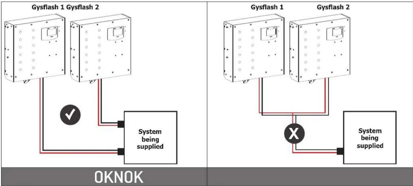
flowchart
graph TD
    subgraph Gysflash 1
        A1["Gysflash 1"] --> B1["System being supplied"]
        A2["Gysflash 2"] --> B1
        A3["Gysflash 2"] --> B2["System being supplied"]
        B1 --> C["OKNOK"]
        B2 --> C
    end
    subgraph Gysflash 1
        D1["Gysflash 1"] --> E1["System being supplied"]
        D2["Gysflash 2"] --> E1
        D3["Gysflash 2"] --> E2["System being supplied"]
        E1 --> F["X"]
        E2 --> F
        F --> C
    end
    subgraph Gysflash 2
        G1["Gysflash 1"] --> H["System being supplied"]
        G2["Gysflash 2"] --> H
        G3["Gysflash 2"] --> H
        H --> I["System being supplied"]
    end
- Method n°2 : With parallelisation modules (PHM + SHM) → Multi-charger Mode
These Gysflash units can also be parallelized using an SHM module, which manages communication between the various Gysflashes (via the SMC ports) and a PHM module, which connects the various power outputs together to form a single, more powerful output.
See the SHM and PHM parallelisation module manuals for more details on installation and use.
Note: The Gysflash units connected must be identical.
Compatible modes:
| CHARGE SUPPLY AUTO-SELECT POWER-UP | |||
| √√√√ | |||
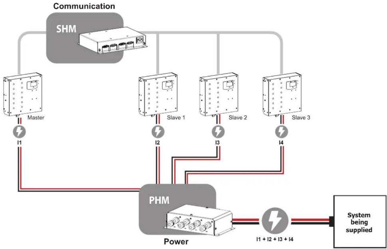
flowchart
graph TD
    A["Communication"] --> B["SHM"]
    B --> C["Master"]
    C --> D["I1"]
    D --> E["PHM"]
    E --> F["Power"]
    F --> G["I1 + I2 + I3 + I4"]
    G --> H["System being supplied"]
    C --> I["Slave 1"]
    C --> J["Slave 2"]
    C --> K["Slave 3"]
    E --> L["+"]
    style A fill:#ccc,stroke:#333
    style B fill:#ccc,stroke:#333
    style C fill:#ccc,stroke:#333
    style D fill:#ccc,stroke:#333
    style E fill:#ccc,stroke:#333
    style F fill:#ccc,stroke:#333
    style G fill:#ccc,stroke:#333
    style H fill:#ccc,stroke:#333
LIST OF ERROR CODES
| Error code Meaning | Solutions | |
| Err01: Int_1 - Err02: Int_2Err23: Int_3 - Err24: Int_4 | Electronic faultDefective unit | Contact your distributor |
| Err03: Fuse_NOK Output fuse out of order Have the fuse replaced by a qualified person | ||
| Err04: T>Tmax Abnormal overheating Contact your distributor | ||
| Err05: (+)↔Reverse polarity on clamps | Connect the red clamp to the (+) and the black clamp to the (-) of the battery. | |
| Err06: U>_V | Overvoltage detected at the clamp terminals | Disconnect the clamps |
| Err07: No_contact No contact on the Gysflash output | Check that the Gysflash is properly connected to the device that you wish to supply power to. | |
| Err08: U<__V Abnormally low battery voltage | Check that the selected mode is compatible with the battery voltage (e. g. : 6 V battery on 24 V mode) | |
| Charge the battery via CHARGE mode | ||
| Battery to be replaced | ||
| Err09: U>__V Abnormally high battery voltage | Check that the selected mode is compatible with the battery voltage (e. g. : 12 V battery on 24 V mode) | |
| Err10: U>2.0V | Short-circuit detected during the charge process | Check the assembly |
| Err11: Time_Out | Activation of the duration limit There is a consumer on the battery, interfering with the charge | |
| Abnormally long charge Battery to be replaced | ||
| Err12: Q>___Ah Tripping the overload protection | There is a consumer on the battery, interfering with the charge | |
| Battery to be replaced | ||
| Err13: U<__V | Abnormally low battery voltage during charge monitoring | Battery to be replaced |
| Err14: Bat_UVP | Abnormally low battery voltage during UVP Wake up | Presence of a short circuit, check the assembly |
| Battery to be replaced | ||
| Err15: U<__V Battery too low | Check that the selected mode is compatible with the battery voltage (e. g. : 24 V battery in 12 V mode) | |
| Battery to be replaced | ||
| Err16: Bat_NOK | Battery out of order | Battery to be replaced |
| Err17: Recov_NOK | Battery recovery failure | Battery to be replaced |
| Err18: U>0V | Presence of voltage at clamp terminals during cable calibration | Check the assembly |
| Err19: Cable_NOK Cable calibration failure | Charging cables to be replaced | |
| Poor connection, check assembly | ||
| Err20: U<__V | Abnormal undervoltage protection activated | Presence of a short circuit, check the assembly |
| Err21: U<__V ou Err22: U<__V | Abnormally low battery voltage during charging | Battery to be replaced |
| Presence of a consumer on the battery | ||
 | Stick not detected | Check that the USB stick is correctly connected to the Gysflash |
 | No configuration file (.gfc) is present on the stick | Check that the files are present in the root of the USB stick. Do not put them in a folder or sub-folder. |
 | Corrupted file | The file you are trying to access is corrupted. Delete and reinstall the file on the stick. |
| Err25: U>__V Voltage present on the clamps. | Battery is not in UVP protection state, so there's no need to run the Power-up mode. | |
| Err26: Power Up Fail | Battery reactivation failed. | Check that the clamps are properly connected to the battery and repeat the operation. |
| Err27: Cable_NOK | Multi-charger mode:Parallel connection of charging cables failed | Charging cables to be replaced. |
| Poor connection, check assembly (PHM). | ||
| To revert back to running a single Gysflash, select OFF for the Multi-charger function. | ||
| Err28: COM_NOK | Multi-charger mode: Gysflash communication failure | No communication, check SHM assembly and SLAVE X device configuration. |
| To revert back to running a single Gysflash, select OFF for the Multi-charger function. | ||
| Err29 : Time_Out_2 Maximum runtime limit exceeded | Disconnect the Gysflash output, or press the SART/STOP button to clear the error. | |
| Err30 : No Bat No battery at the | Gysflash output Check that the Gysflash is correctly connected to the battery | |
| Err31 : COM_NOK | Multi-charger mode : Gysflash connected to the wrong SHM channel | Check that the Gysflash Master is indeed on SHM channel no. 1 and the Gysflash Slaves on the other channels. |
| To switch back to single-charger operation, press the START/ STOP button, enter the administrator code and select OFF for the Multi-charger function. | ||
FIRMWARE UPDATE (.EGF)
Update Procedure using USB key:
- First of all, make sure that the «.egf» file matching the new firmware is on the USB stick. This file must not be located in a folder or subfolder of the USB stick.
Warning: The USB stick must contain only one «.egf» file and must be formatted in FAT32.
- Switch the Gysflash off using the On/Off switch ①
- Connect the USB stick to the Gysflash
- Hold down the SELECT button
- Switch on the Gysflash using the On/Off switch ① while holding down the SELECT button until the update starts. During the update, «System Update V__._» appears on the screen.
- When the update is complete, the Gysflash displays «Update completed», and automatically restarts after 3 seconds.
WARRANTY
The warranty covers all defects or manufacturing faults for a period of two years starting from the date of purchase (parts and labour).
The warranty does not cover:
- Any other damage caused during transport.
- The general wear and tear of parts (i.e.: cables, clamps, etc.).
- Incidents caused by misuse (incorrect power supply, dropping or dismantling).
- Environment-related faults (such as pollution, rust and dust).
In the event of a breakdown, please return the item to your distributor, along with:
- a dated proof of purchase (receipt or invoice etc.).
- a note explaining the malfunction.
text_image
Password-Manager Password 1 -2-3-4 Auto-select Laden SupplyINBETRIEBNAHME
text_image
Auto-select Start
text_image
Auto-select kein KontaktAuto-Select inaktiv Auto-Select aktiv
text_image
① Power-up 12 V n°01 ②text_image
Power-up 14.0V 113A 00:00:25 5.8 Ah ① ② ④ ③ ⑤text_image
Password-Manager Password 1 -2-3-4 Auto-select mLaden Supply Power-up
+ Option
text_image
Icon set with document, upload, download, and connection symbols arranged in a rowDÉCLARATION DE CONFORMITÉ
CE
DECLARATION OF CONFORMITY
CE
GYS SAS declares on our own responsibility that the new and unused following product GYSFLASH CNT to which this declaration refers, is manufactured in conformity with the following Regulations :
• Directive 2014/35/EU, Low Voltage, of 26/02/2014
• Directive 2011/65/EU, RoHS2, of08/06/2011
• Directive 2015/863, Annex II of RoHS2, of 31/03/2015
• Directive 2014/30/EU, EMC (Electromagnetic Compatibility), of 26/02/2014
and as a consequence is in compliance with the harmonized standard:
GYS SAS declares on our own responsibility that the new and unused following product GYSFLASH CNT to which this declaration refers, is manufactured in conformity with the following Regulations :
• Electrical Equipment (Safety) Regulations 2016
• Electromagnetic Compatibility Regulations 2016
• The Restriction of the Use of Certain Hazardous Substances in Electrical and Electronic Equipment Regulations 2012
and as a consequence is in compliance with the harmonized standard:
CEO - Chief Executive
text_image
Diagram of an electronic device rear panel with labeled ports and connectors, showing numbered labels for component identification.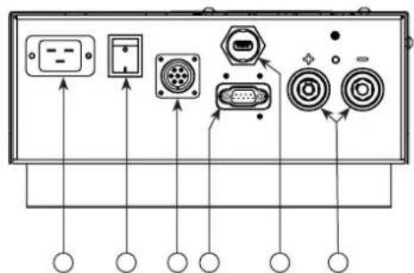
text_image
Diagram of electronic device rear panel with labeled ports and connectors, showing connections to input/output pins.natural_image
Technical line drawing of three mechanical components with a magnified inset showing a labeled component 'M6' (no text or symbols on the components themselves)
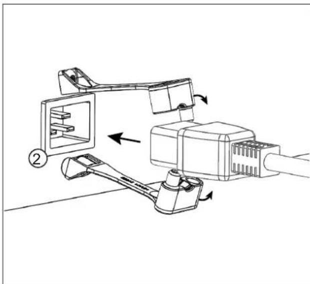
Use NFC 20-130 6.5 mm diameter round cable lugs, suitable for the cable cross-section, and crimped in accordance with the manufacturer's recommendations.
Insert the sleeve securely, as far as it will go, so that no live part is accessible.
text_image
Technical diagram of a mechanical device with labeled components and numbered parts2
natural_image
Technical line drawing of a mechanical assembly with labeled components (no text or symbols)3
natural_image
Technical line drawing of a mechanical device with screw and housing components (no text or symbols)