PC415X - Professional audio equipment Adj - Free user manual and instructions
Find the device manual for free PC415X Adj in PDF.


User questions about PC415X Adj
0 question about this device. Answer the ones you know or ask your own.
Ask a new question about this device
Download the instructions for your Professional audio equipment in PDF format for free! Find your manual PC415X - Adj and take your electronic device back in hand. On this page are published all the documents necessary for the use of your device. PC415X by Adj.
USER MANUAL PC415X Adj
text_image
PC415 arid P0006 TIFL18 DINX THRU DINX OUT 1 DINX OUT 2 DINX OUT 3 DINX OUT 4 DC DC DC DC DC DC DC DC DC DC DC DC DC DC DC DC DC DC DC DC DC DC DC DC DC DC DC DC DC DC DC DC DC DC DC DC DC DC DC DC DC DC DC DC DC DC DC DC DC DC PC415PC4I5X
User Manual
©2025 ADJ Products, LLC all rights reserved. Information, specifications, diagrams, images, and instructions herein are subject to change without notice. ADJ Products, LLC logo and identifying product names and numbers herein are trademarks of ADJ Products, LLC. Copyright protection claimed includes all forms and matters of copyrightable materials and information now allowed by statutory or judicial law or hereinafter granted. Product names used in this document may be trademarks or registered trademarks of their respective companies and are hereby acknowledged. All non-ADJ Products, LLC brands and product names are trademarks or registered trademarks of their respective companies.
ADJ Products, LLC and all affiliated companies hereby disclaim any and all liabilities for property, equipment, building, and electrical damages, injuries to any persons, and direct or indirect economic loss associated with the use or reliance of any information contained within this document, and/or as a result of the improper, unsafe, insufficient and negligent assembly, installation, rigging, and operation of this product.
ADJ PRODUCTS LLC World Headquarters
6122 S. Eastern Ave. | Los Angeles, CA 90040 USA
Tel: 800-322-6337 | www.adj.com lsupport@adj.com
ADJ Supply Europe B.V.
ADJ SERVICE EUROPE - Monday - Friday 08:30 to 17:00 CET
Junostraat 2 | 6468 EW Kerkrade | Netherlands
+31 45 546 85 60 | info@adj.eu | support@adj.eu
Europe Energy Saving Notice
Energy Saving Matters (EuP 2009/125/EC)
Saving electric energy is a key to help protecting the environment. Please turn off all electrical products when they are not in use. To avoid power consumption in idle mode, disconnect all electrical equipment from power when not in use. Thank you!
DOCUMENT VERSION

Due to additional product features and/or enhancements, an updated version of this document may be available online.
Please check www.adj.com for the latest revision/update of this manual before beginning installation and/or programming.
| Date | Document Version | Software Version > | Modes Notes | |
| 07/16/24 1 | 1.00 N/A Initial Release | |||
CONTENTS
General Information 4
Limited Warranty (USA Only) 5
Safety Guidelines 6
Overview 7
Front Controls & Connections 8
Rear Controls & Connections 9
Installation Guidelines 10
Frequency & Wireless Location Guidelines 13
System Menu 14
DMX Setup 17
DMX Traits 19
Remote Device Management (RDM) 20
Maintenance Guidelines 21
Firmware Updates 22
Specifications 23
Dimensional Drawings 24
Optional Accessories I FCC Statement 25
GENERAL INFORMATION
INTRODUCTION
Please read and understand the instructions in this manual carefully and thoroughly before attempting to operate this device. These instructions contain important safety and use information.
This product is intended for use by professionally trained personnel only, and is not suitable for private use.
Unpacking
Every device has been thoroughly tested and has been shipped in perfect operating condition. Carefully check the shipping carton for damage that may have occurred during shipping. If the carton is damaged, carefully inspect the device for damage, and be sure all accessories necessary to install and operate the device have arrived intact. In the event damage has been found or parts are missing, please contact our customer support team for further instructions. Please do not return this device to your dealer without first contacting customer support. Please do not discard the shipping carton in the trash. Please recycle whenever possible.
DESCRIPTION
The PC415X is an innovative, all-in-one solution for lighting professionals, venues, and production teams seeking a reliable, efficient, and versatile hub for power distribution and DMX control. This state-of-the-art device integrates three essential functions into a single, compact, rack-mountable unit: a 4-output power distribution center, an advanced Aria X2 wireless DMX transceiver, and a 4-output DMX/RDM splitter. This powerful combination delivers exceptional control and flexibility, making the PC415X an invaluable asset for live events, stage productions, touring, and fixed installations.
BOX CONTENTS
1.83M locking power cable
2 antennas
CUSTOMER SUPPORT
Contact ELATION Service for any product related service and support needs. Also visit forums.elationlighting.com with questions, comments or suggestions.
ELATION SERVICE USA - Monday - Friday 8:00am to 4:30pm PST 323-582-3322 | support@elationlighting.com
ELATION SERVICE EUROPE - Monday - Friday 08:30 to 17:00 CET +31 45 546 85 63 | support@elationlighting.eu
REPLACEMENT PARTS - please visit parts.elationlighting.com

IMPORTANT NOTICE!
THERE ARE NO USER SERVICEABLE PARTS INSIDE THIS UNIT. DO NOT ATTEMPT ANY REPAIRS YOURSELF; DOING SO WILL VOID YOUR MANUFACTURER'S WARRANTY. DAMAGES RESULTING FROM MODIFICATIONS TO THIS FIXTURE AND/OR THE DISREGARD OF SAFETY INSTRUCTIONS AND GUIDELINES IN THIS MANUAL VOID THE MANUFACTURER'S WARRANTY AND ARE NOT SUBJECT TO WARRANTY CLAIMS AND/OR REPAIRS.
LIMITED WARRANTY (USA ONLY)
A. ADJ Products, LLC hereby warrants, to the original purchaser, ADJ Products, LLC products to be free of manufacturing defects in material and workmanship for a prescribed period from the date of purchase (see specific warranty period on reverse). This warranty shall be valid only if the product is purchased within the United States of America, including possessions and territories. It is the owner's responsibility to establish the date and place of purchase by acceptable evidence, at the time service is sought.
B. For warranty service, you must obtain a Return Authorization number (RA#) before sending back the product-please contact ADJ Products, LLC Service Department at 800-322-6337. Send the product only to the ADJ Products, LLC factory. All shipping charges must be pre-paid. If the requested repairs or service (including parts replacement) are within the terms of this warranty, ADJ Products, LLC will pay return shipping charges only to a designated point within the United States. If the entire instrument is sent, it must be shipped in its original package. No accessories should be shipped with the product. If any accessories are shipped with the product, ADJ Products, LLC shall have no liability whatsoever for loss of or damage to any such accessories, or for the safe return thereof.
C. This warranty is void of the serial number has been altered or removed; if the product is modified in any manner which ADJ Products, LLC concludes, after inspection, affects the reliability of the product, if the product has been repaired or service by anyone other than ADJ Products, LLC factory unless prior written authorization was issued to purchaser by ADJ Products, LLC; if the product is damaged because not properly maintained as set forth in the instruction manual.
D. This is not a service contact, and this warranty does not include maintenance, cleaning or periodic check up. During the period specified above, ADJ Products, LLC will replace defective parts at its expense with new or refurbished parts, and will absorb all expenses for warrant service and repair labor by reason of defects in material or workmanship. The sole responsibility of ADJ Products, LLC under this warranty shall be limited to the repair of the product, or replacement thereof, including parts, at the sole discretion of ADJ Products, LLC. All products covered by this warranty were manufactured after August 15, 2012, and bear identifying marks to that effect.
E. ADJ Products, LLC reserves the right to make changes in design and/or improvements upon its products without any obligation to include these changes in any products theretofore manufactured.
F. No warranty, whether expressed or implied, is given or made with respect to any accessory supplied with products described above. Except to the extent prohibited by applicable law, all implied warranties made by ADJ Products, LLC in connection with this product, including warranties of merchantability or fitness, are limited in duration to the warranty period set forth above. And no warranties, whether expressed or implied, including warranties of merchantability or fitness, shall apply to this product after said period has expired. The consumer's and/or Dealer's sole remedy shall be such repair or replacement as is expressly provided above; and under no circumstances shall ADJ Products, LLC be liable for any loss or damage, direct or consequential, arising out of the use of, or inability to use, this product.
G. This warranty is the only written warranty applicable to ADJ Products, LLC Products and supersedes all prior warranties and written descriptions of warranty terms and conditions heretofore published.
LIMITED WARRANTY PERIODS
- Non L.E.D. Lighting Products = 1-year (365 days) Limited Warranty (Such as: Special Effect Lighting, Intelligent Lighting, UV lighting, Strobes, Fog Machines, Bubble Machines, Mirror Balls, Par Cans, Trussing, Lighting Stands etc. excluding LED and lamps)
• Laser Products = 1 Year (365 Days) Limited Warranty (excludes laser diodes which have 6 month limited warranty) - L.E.D. Products = 2-year (730 days) Limited Warranty (excluding batteries which have a 180 day limited warranty)
Note: 2 Year Warranty only applies to purchases within the United States.
• StarTec Series = 1 Year Limited Warranty (excluding batteries which have a 180 day limited warranty) - ADJ DMX Controllers = 2 Year (730 Days) Limited Warranty
SAFETY GUIDELINES
The PC415X is a sophisticated piece of electronic equipment. To ensure smooth and safe operation, strictly follow all instructions and guidelines in this manual. Elation Professional is not liable for injuries or damages resulting from misuse of the device due to failure to adhere to the information provided in this manual. Use only the original parts and accessories included with the PC415X. Any modifications to the device or its accessories will void the manufacturer's warranty and increase the risk of damage or personal injury.

PROTECTION CLASS 1 - FIXTURE MUST BE PROPERLY GROUNDED

THERE ARE NO USER SERVICEABLE PARTS INSIDE THIS UNIT. DO NOT ATTEMPT ANY REPAIRS YOURSELF; DOING SO WILL VOID YOUR MANUFACTURER'S WARRANTY. DAMAGES RESULTING FROM MODIFICATIONS TO THIS FIXTURE AND/OR THE DISREGARD OF SAFETY INSTRUCTIONS AND GUIDELINES IN THIS MANUAL VOID THE MANUFACTURE'S WARRANTY AND ARE NOT SUBJECT TO ANY WARRANTY CLAIMS AND/OR REPAIRS.

DO NOT PLUG FIXTURE INTO A DIMMER PACK! NEVER OPEN THIS FIXTURE WHILE IN USE! UNPLUG POWER BEFORE SERVICING DEVICE! NEVER TOUCH FIXTURE DURING OPERATION, AS IT MAY BE HOT! KEEP FLAMMABLE MATERIALS AWAY FROM FIXTURE!

INDOOR / DRY LOCATIONS USE ONLY! DO NOT EXPOSE DEVICE TO RAIN AND MOISTURE!
DO NOT shake the device or use excessive force during installation or operation.
DO NOT operate the device if the power cord is frayed, crimped, or damaged, or if any power cord connectors are damaged or do not connect securely and easily.
NEVER force a power cord connector into the device. If the power cord or any connectors are damaged, replace them immediately with a new one of the same power rating.
When installing the device in a suspended environment, always use mounting hardware rated for at least M10 x 25 mm and secure the fixture with an appropriately rated safety cable.
Always disconnect the device from the main power source before performing any service or cleaning procedures.
Only handle the power cord by the plug; never pull the plug by tugging the cord wire.
During initial operation, the device may emit light smoke or a slight odor. This is normal, as excess paint in the interior burns off due to heat from the components, and will decrease over time.
Take regular operational breaks to ensure the device functions reliably for many years.
ONLY use the original packaging and materials to transport the device for service.
OVERVIEW
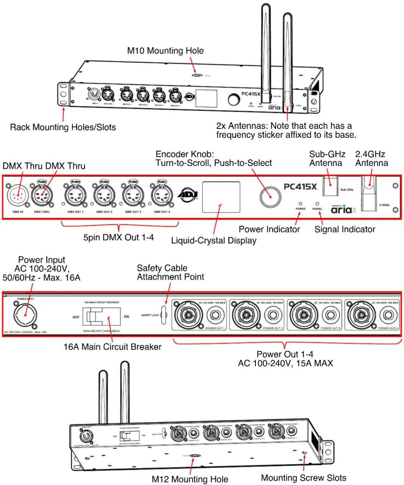
FRONT CONTROLS & CONNECTIONS
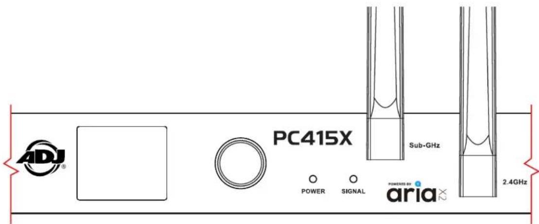
OLED CONTROL PANEL:
The PC415X features a vibrant, high-contrast OLED display, paired with an intuitive Encoder Knob for seamless navigation. This user-friendly interface enables precise and effortless adjustment of all device settings. Simply turn the knob to scroll through menu options and push to select, providing quick and confident control over the fixture's configurations.
text_image
ADJ® PC415X Sub-GHz POWER SIGNAL aria x2 2.4GHzDMX CONNECTIONS:
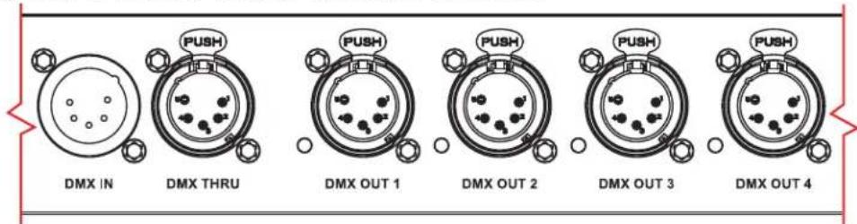
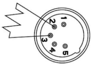
The PC415X features 5-pin male and female XLR connectors for DMX Input, Thru, and Output connections. The pin configuration is as follows: Pin 1 to shield (ground), Pin 2 to cold (−), and Pin 3 to hot (+). Pins 4 and 5 are not used. Carefully connect DMX cables to the corresponding ports, ensuring proper alignment. To prevent damage to the DMX ports, provide strain relief and support for connected cables. Do not connect FOH (Front of House) snakes directly to the ports.
| PinConnection |
| 1 Com |
| 2 Data - |
| 3 Data + |
| 4 Not connected |
| 5 Not connected |
text_image
DMX IN PUSH DMX THRU PUSH DMX OUT 1 PUSH DMX OUT 2 PUSH DMX OUT 3 PUSH DMX OUT 4REAR CONTROLS & CONNECTIONS
AC CONNECTIONS
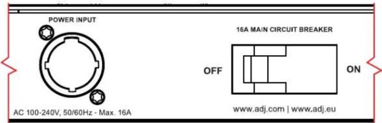
The PC415X is rated for AC 100–240V, 50/60 Hz, and must only be connected to mains power within this range. Connecting the device to power outside this range may cause damage, which is not covered under warranty. In the USA and Canada, the PC415X includes a power cable with a NEMA 5-15P plug. This approved cable must be used in North America.
text_image
POWER INPUT AC 100-240V, 50/60Hz - Max. 16A 16A MAIN CIRCUIT BREAKER OFF ON www.adj.com | www.adj.euAC INPUT & 16A MAIN CIRCUIT BREAKER

text_image
AC 100-240V, 15A MAX POWER OUT 1 AC 100-240V, 15A MAX POWER OUT 2 AC 100-240V, 15A MAX POWER OUT 3 AC 100-240V, 15A MAX POWER OUT 4AC POWER OUT CONNECTORS #1 - 4, 100-240V, 15A MAX
INSTALLATION GUIDELINES

DISCONNECT POWER BEFORE PERFORMING ANY MAINTENANCE!

ELECTRICAL CONNECTIONS
A qualified electrician should be used for all electrical connections and/or installations.

USE CAUTION WHEN POWER LINKING OTHER MODEL DEVICES AS THE POWER CONSUMPTION OF OTHER MODEL DEVICES MAY EXCEED THE MAXIMUM POWER OUTPUT OF THIS DEVICE. CHECK SILK SCREEN FOR MAXIMUM AMPS.

THE PC415X IS DESIGNED TO BE TRUSS-MOUNTED; HOWEVER, IT CAN BE USED STAND-ALONE, WHERE THE DEVICE MUST SIT ON A FIRM FLAT SURFACE.
Device MUST be installed following all local, national, and country commercial electrical and construction codes and regulations.
POWER LINKING

USE CAUTION WHEN POWER LINKING AS THE POWER CONSUMPTION MAY EXCEED THE MAXIMUM POWER OUTPUT ON THIS DEVICE. CHECK SILK SCREEN FOR MAXIMUM AMPS.
INSTALLATION GUIDELINES
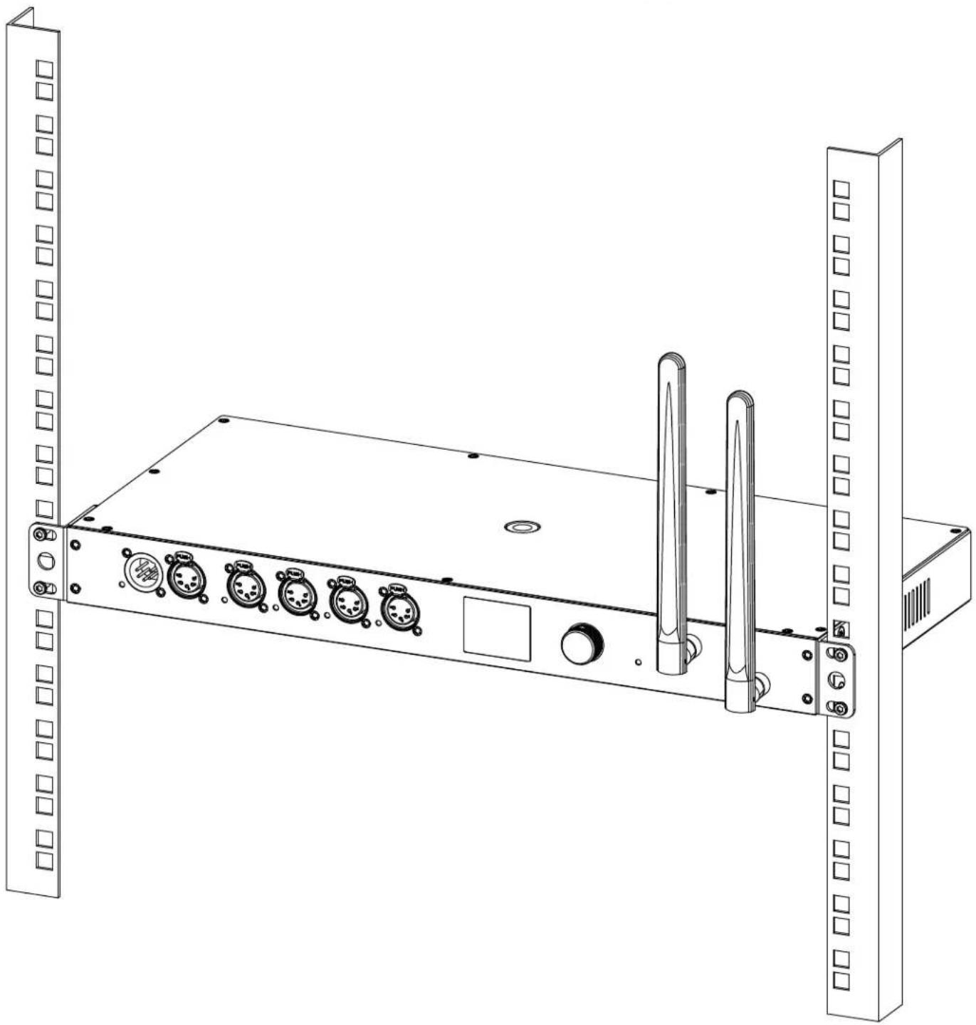
RACK MOUNT INSTALLATION
- Slide the PC415X units into the rear of the Rack Shelf.
- Align the mounting holes on the bottom of each Aria X2 Transceiver with the corresponding holes on the Rack Shelf, and secure each unit to the Rack Shelf with (4x) M4x6 screws.
natural_image
Line drawing of a server rack with multiple ports and connectors (no text or symbols)INSTALLATION GUIDELINES
TRUSS MOUNT INSTALLATION
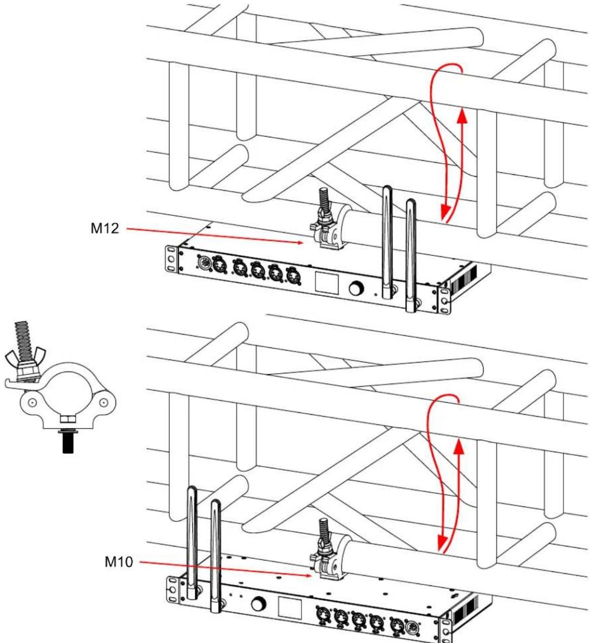
To mount the PC415X to a truss, use an 18.8 mm steel M10x20 mm or M12x25 mm bolt (not included). For the M10 mounting hole located on the bottom of the fixture, or the M12 mounting hole located on the top, insert the appropriate bolt through the corresponding mounting hole of the clamp (not included) and thread it into the fixture base. Ensure the bolt is threaded at least 18 mm (0.7 in.) into the fixture base for secure attachment.
text_image
M12 M10
FALLING FIXTURES CAN CAUSE SEVERE INJURY OR SERIOUS EQUIPMENT DAMAGE! FOR THIS REASON, FIXTURES SHOULD BE INSTALLED AND INSPECTED ONLY BY QUALIFIED PERSONNEL. DO NOT INSTALL THE UNIT IF YOU LACK THE QUALIFICATIONS TO DO SO, OR IF YOU HAVE DOUBTS ABOUT THE SAFETY AND SECURITY OF THE INSTALLATION SETUP OR LOCATION!

ALWAYS ATTACH A SAFETY CABLE WHENEVER INSTALLING THIS FIXTURE IN A SUSPENDED ENVIRONMENT TO ENSURE THE FIXTURE WILL NOT FALL IF THE CLAMP FAILS.
FREQUENCY & WIRELESS LOCATION GUIDELINES
2.4 GHz Versus Sub-GHz Frequencies:
Sub-GHz Frequencies (below 1 GHz): Offer better range and penetration through walls, buildings, or obstacles. Experience less interference than 2.4 GHz, ideal for long-distance or challenging environments (e.g., rural or industrial venues). US: 902–928 MHz (FCC-regulated). EU: 863–870 MHz (ETSI-regulated). Verify local regulations for usage.
2.4 GHz Frequencies: Support higher data rates and bandwidth, suitable for urban areas with managed interference. More congested due to Wi-Fi, Bluetooth, and other devices, risking signal disruption.
ANTENNA ORIENTATION & INSTALLATION
Use the following guidelines to optimize wireless communication between transmitting and receiving PC415X units:
Mount Upright: Install the PC415X upright on a stable surface or truss, with antennas pointing upward at 90 degrees for maximum signal strength.
Upside-Down Mounting: If upside down, adjust antennas to point upward toward the ceiling, gently securing them without over-tightening SMA connectors.
Elevate Units: Position units at least 9.8 ft. (3 m) above ground or audience to minimize interference from people or obstacles.
Align Antennas: Keep antennas on transmitting and receiving PC415X units vertical and aligned, as misaligned angles (e.g., 90° vs. 45°) weaken signals.
Ensure Line of Sight: Maintain clear line of sight between antennas of transmitting and receiving units, avoiding metal trusses, walls, or crowds, and use Sub-GHz frequencies in high-interference venues as described above.
Plan and Test: Plan the installation to account for environmental factors, testing signal strength and adjusting positions for consistent performance.
Troubleshoot: If signal issues occur, verify all units use the same frequency and channel, check for interference, and replace damaged antennas with genuine ADJ parts.
9.8 ft (3m)
Above Ground

natural_image
Silhouette of a group of people with an upward arrow in the background (no text or symbols)SYSTEM MENU
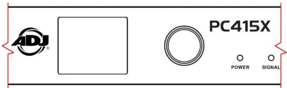
The PC415X is equipped with a clear, vibrant LCD display screen, paired with a user-friendly Encoder Knob designed for seamless navigation. This intuitive interface allows users to effortlessly adjust all device settings with precision. Simply turn the knob to scroll through options and push to select, ensuring quick and confident control over the fixture's various configurations.
text_image
ADJ® PC415X POWER SIGNALSYSTEM MENU
| MAIN MENU OPTIONS (Default Settings in BOLD) | |||
| DMX | Address 1 - 512 | ||
| Channel Mode 1 CH, 2 | CH, 4 CH | ||
| No DMX | Hold 0-60m, Indefinitely | ||
| Blackout | |||
| Auto ON | Output 1 | ||
| Output 2 | |||
| Output 3 | |||
| Output 4 | |||
| Manual | |||
| Personality | Protocol | DMX Primary, Secondary | |
| Aria Primary, Secondary | |||
| DMX Only | |||
| Aria Only | |||
| RDM ON / OFF | |||
| Aria | Frequency | 2.4Ghz. | |
| Sub Gig US | |||
| Sub Gig EU | |||
| 2.4 Ghz. CH 00~15 | |||
| Sub Gig CH 00~09 | |||
| Mesh ON / OFF | |||
| Bluetooth ON / OFF | |||
| Power | ON / OFF via DMX ON | / OFF | |
| ON / OFF with DMX ON | / OFF | ||
| ON / OFF via Aria ON / Scheduler | OFF | ||
| Display | Timeout | OFF / 30sec.-10min. | |
| Passcode | Enable / Disable | ||
| Edit Passcode | Passcode (xxx) | ||
| Screen Rotation | YES / NO / Auto | ||
| LEDs 0-9 (5) | |||
| Device Label | PC414 | ||
| Clock | Set Date | xx-xx-xxxx - Monday - Sunday | |
| Format | 12 or 24 Hour | ||
| Set Time | (HH:MM AM/PM) or (HH:MM) | ||
| Daylight Savings | Enable / Disable | ||
| Factory Reset Passcode: (050) YES / NO | |||
| Manual | Power Output 1 | ON / OFF | 0-60m / Indefinitely |
| Power Output 2 | ON / OFF | ||
| Power Output 3 | ON / OFF | ||
| Power Output 4 | ON / OFF | ||
SYSTEM MENU
| MAIN MENU OPTIONS (Default Settings in BOLD) | |||
| Output Delay | All Power Outputs All 0 - 120s | ||
| Unit Power Outputs | Power Output 1 0 - 120s | ||
| Power Output 2 0 - 120s | |||
| Power Output 3 0 - 120s | |||
| Power Output 4 0 - 120s | |||
| Scheduler | Scheduler Enable / Disable | ||
| Event 1 Event 2 Event 3 Event 4 Event 5 Event 6 Event 7 Event 8 | Power Output 1 ON / OFF | ||
| Power Output 2 ON / OFF | |||
| Power Output 3 ON / OFF | |||
| Power Output 4 ON / OFF | |||
| Event ON Time HH:MM | AM/PM | ||
| Event OFF Time HH:MM | AM/PM | ||
| Days | Monday | ||
| Tuesday | |||
| Wednesday | |||
| Thursday | |||
| Friday | |||
| Saturday | |||
| Sunday | |||
| DMX Splitter | DMX OUT 1 DMX OUT 2 DMX OUT 3 DMX OUT 4 | DMX Primary, Secondary | |
| Aria Primary, Secondary | |||
| DMX Only | |||
| Aria Only | |||
| Information | Software Version x.xx | ||
| Label xxxxxx | |||
| Aria ID xxxxxx | |||
DMX SETUP
DMX-512:
Digital Multiplex (DMX) is a universal protocol widely adopted by lighting and controller manufacturers to facilitate communication between intelligent fixtures and controllers. A DMX controller transmits DMX data instructions to fixtures, sending serial data through the DATA IN and DATA OUT XLR terminals found on all DMX-compliant fixtures. Most controllers feature only a DATA OUT terminal, while fixtures typically include both DATA IN and DATA OUT terminals for daisy-chaining.
DMX LINKING:
DMX serves as a standardized protocol, enabling fixtures and controllers from different manufacturers to be interconnected and operated from a single DMX-compliant controller. To ensure reliable DMX data transmission with multiple fixtures, use the shortest cable path possible. The order of fixtures in a DMX chain does not affect their DMX addressing. For example, a fixture assigned DMX address 1 can be placed anywhere in the chain—whether at the beginning, end, or middle—and the controller will send data for address 1 to that fixture, regardless of its position.
DATA CABLE (DMX CABLE) REQUIREMENTS:
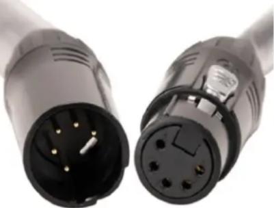
The PC415X supports control via the DMX-512 protocol, with the DMX address configured electronically using the unit's front panel controls. Both the PC415X and the DMX controller require approved DMX-512 110-ohm data cables for reliable input and output. Accu-Cable DMX cables are recommended. If constructing custom cables, use standard 110–120-ohm shielded cable, available at most professional sound and lighting retailers. Cables should feature a 3-pin or 5-pin male XLR connector on one end and a female XLR connector on the other. DMX cables must be daisy-chained and cannot be split or branched.
natural_image
Close-up of two black electrical connectors with gold pins, no visible text or symbolsLINE TERMINATION:
For longer cable runs, a terminator may be required on the last fixture to prevent erratic behavior. A terminator is a 110–120-ohm, 1/4-watt resistor connected between pins 2 and 3 (DATA + and DATA −) of a male XLR connector. Insert the terminator into the female XLR DATA OUT connector of the final fixture in the daisy chain to terminate the line. Using a cable terminator, such as the ADJ Z-DMX/T, significantly reduces the likelihood of signal interference and erratic performance.
text_image
1 2 3 4 5A DMX512 terminator reduces signal errors, avoiding most signal reflection interference. Connect PIN 2 (DMX-) and PIN 3 (DMX+) of the last fixture in series with a 120 Ohm, 1/4 W Resistor to terminate the DMX512.
DMX SETUP
CONNECTING DMX CONTROLLER TO PC415X
The PC415X offers versatile connectivity, allowing it to receive a DMX signal from a controller and transmit it to other devices using multiple protocols. Signals can be sent or received through the Aria X2 antennas (wireless) or a physical DMX connection, providing flexible configuration options.
You can use either the Aria wireless protocol or a physical DMX cable for both input and output, in any combination that suits your setup. For example, the device can receive a signal via Aria and output via DMX, or vice versa, without restrictions on simultaneous use of the same method for input and output.
To configure the input and output methods, navigate to the Transceiver sub-menu within the System Menu on the PC415X's OLED control panel. Refer to the System Menu section of this manual for detailed instructions on menu navigation and settings.
Transmitter Mode: When the PC415X is set to transmit, the signal indicator illuminates orange. You can select either the 2.4 GHz or Sub-GHz frequency band and choose a specific channel to optimize wireless performance.
Receiver Mode: To configure the PC415X as a receiver, set it to the same frequency (2.4 GHz or Sub-GHz) and channel as the transmitting device. When properly synchronized, the signal indicator turns green, indicating the device is ready to receive and control lighting functions.
ARIA X2 TRANSCEIVER AS TRANSMITTER
When the Aria X2 Transceiver is connected to a DMX controller, the DMX signal indicator on the controller turns green, confirming a successful connection. The PC415X's signal indicator will illuminate orange, indicating that the device is actively transmitting the DMX signal wirelessly to other units.
DMX TRAITS
| CHANNEL | DMX VALUE | FUNCTION PERCENT | SETTING | ||
| 1CH 2CH | 4CH | ||||
| 1 | 000-127 | OUTPUTS #1 - 4 | OFF | ||
| 128-255 ON | |||||
| 1 | 000-127 | OUTPUTS #1 - 2 | OFF | ||
| 128-255 ON | |||||
| 2 | 000-127 | OUTPUTS #3 - 4 | OFF | ||
| 128-255 ON | |||||
| 1 | 000-127 | OUTPUT #1 | OFF | ||
| 128-255 ON | |||||
| 2 | 000-127 | OUTPUT #2 | OFF | ||
| 128-255 ON | |||||
| 3 | 000-127 | OUTPUT #3 | OFF | ||
| 128-255 ON | |||||
| 4 | 000-127 | OUTPUT #4 | OFF | ||
| 128-255 ON | |||||
REMOTE DEVICE MANAGEMENT (RDM)
NOTE: for RDM to work properly, RDM enabled equipment must be used throughout the entire system, including DMX data splitters and wireless systems.
Remote Device Management (RDM) is a protocol that sits on top of the DMX512 data standard for lighting, allowing the DMX systems of the fixtures to be modified and monitored remotely. This protocol is ideal for instances in which a unit is installed in a location that is not easily accessible.
With RDM, the DMX512 system becomes bi-directional, allowing a compatible RDM enabled controller to send out a signal to devices on the wire, as well as allowing the fixture to respond (known as a GET command). The controller can then use its SET command to modify settings that would typically have to be changed or viewed directly via the unit's display screen, including the DMX Address, DMX Channel Mode, and Temperature Sensors.
MAINTENANCE GUIDELINES
DISCONNECT POWER BEFORE PERFORMING ANY MAINTENANCE!
CLEANING
Frequent cleaning is recommended to ensure proper function, optimized light output, and an extended life. The frequency of cleaning depends on the environment in which the fixture operates: damp, smoky, or particularly dirty environments can cause greater accumulation of dirt on the fixture's optics. Clean the external lens surface periodically with a soft cloth to avoid dirt/debris accumulation.
NEVER use alcohol, solvents, or ammonia-based cleaners.
MAINTENANCE
Regular inspections are recommended to ensure proper function and extended life.
There are no user serviceable parts inside this fixture, please refer all other service issues to an authorized ADJ service technician. Should you need any spare parts, please order genuine parts from your local ADJ dealer.
Please refer to the following points during routine inspections:
- A detailed electrical check by an approved electrical engineer every three months, to make sure the circuit contacts are in good condition in order to prevent overheating.
- Be sure all screws and fasteners are securely tightened at all times. Loose screws may fall out during normal operation, resulting in damage or injury as larger parts could fall.
- Check for any deformations on the housing, rigging hardware, and rigging points (ceiling, suspension, trussing).
- Electric power supply cables must not show any damage, material fatigue, or sediments.
- NEVER remove the ground prong from the power cable.
FIRMWARE UPDATE
Firmware updates for the PC415X can be performed wirelessly via Bluetooth using the Aria X2 iOS App, available for download on the Apple App Store. This convenient over-the-air update process allows you to keep your devices up to date with minimal effort.
Types of Firmware Updates:
There are two firmware components that can be updated through the app:
- Fixture Update – Updates the internal program that runs the PC415X.
- Aria Update – Updates the program that runs the Aria module.
Important: Ensure that the Aria firmware is up to date on each fixture before performing a Fixture firmware update.
Performing a Firmware Update:
- Open the Aria X2 iOS App on your device.
- Navigate to the "Settings" tab.
- Select the type of firmware you wish to update: Fixture or Aria.
- A list of available fixtures will appear. Aria firmware updates can be applied to all devices in a single batch if desired. However, Fixture firmware updates must be performed by fixture model—do not mix different models in a single update batch. Use the checkmark toggles to select or deselect fixtures for the update. Updates can be scheduled for any detected devices, even if they are not currently supported with a profile. The app automatically manages connections, so no manual pairing is needed.
- Tap "Select File" at the top of the screen. This will bring up a list of available firmware files.
- Firmware files are stored locally in the app's Firmware folder.
- When connected to the internet, additional files are available via the app's cloud service.
-
Choose the appropriate firmware file from the local or online list.
-
Tap "Update" at the top of the screen to begin the update process.
Note: If multiple devices are selected, the update will proceed sequentially—each device will be updated one after the other.
SPECIFICATIONS
Key Features:
- Multi-functional Design: The PC415X offers 4 power outputs, an Aria X2 transceiver, and DMX/RDM splitter in one device
- Flexible DMX Channel Modes: Operate in 1, 2, or 4 DMX channel modes, ensuring compatibility across different setups
- User-Friendly Control: Navigate with ease using the push button and encoder wheel, complemented by an OLED control menu display
• Event Scheduler: Manage power and DMX outputs with an internal On/Off scheduler for automated operation - Single DMX Universe: Works seamlessly as a single DMX universe transmitter, ideal for precise control over lighting configurations
- Multi-Protocol Support: Features Sub-GHz, 2.4 GHz WiFi, Bluetooth, and proprietary Aria X2 Mesh Protocol for reliable wireless communication
• Future-Ready: Configuration via front panel and app support (app coming soon) for on-the-go adjustments - Mounting Flexibility: Rack-mountable and truss-mountable for versatile installation options
Supported Protocols:
• DMX/RDM: Designed for DMX lighting control, with RDM support planned in a future software release
- Proprietary Protocols: Supports Aria X2 Mesh Protocol and 802.15.4 communication, plus Bluetooth 5.2 for versatile device connectivity
RF Characteristics:
• Frequency Range: Operates between 2404-2480 MHz, with additional EU (863-870 MHz) and US (902-928 MHz) bands.
• Enhanced Reliability: CSMA and planned adaptive frequency hopping ensure minimal interference
• Over-the-Air Updates: Future-proof your setup with OTA updates
Standards & Compliance:
- Safety: Meets EN IEC 62368-1 and BS EN standards for safe operation
• Health & EMC: Complies with EN IEC 62311:2020 and ETSI EMC standards, ensuring safety and low interference
Connectors:
- DMX and Power Options: Features (1) DMX input, (4) DMX outputs, and (4) IP65 locking power outputs with 15A resettable breakers.
- Antenna Compatibility: Equipped with dual 5G JT SMA antennas.
Power Requirements:
- Versatile Power Input: Compatible with AC100-240V 50/60Hz and equipped with a 16A main power switch
- Low Power Consumption: Runs efficiently with minimal power requirements and features a CR2032 lithium battery for critical backup
Physical Specifications:
- Robust Design: Durable IP20 metal enclosure with a digital screen, rotary knob, and safety eyelet
• Temperature Tolerant: Operates in ambient temperatures up to 113°F and humidity below 75% - Compact Dimensions: At just 7.4 lbs, it's designed for easy handling and secure installation
Dimensions & Weight:
• Length: 19" (482mm)
• Width: 9.81" (249.17mm)
• Height: 1.73" (43.80mm)
• Weight: 7.4 lbs (3.36 kg)
Approvals & Included Accessories:
- Approvals: CE, cETLus (pending), IP20-rated for indoor use
- Accessories: Comes with rack ears for a standard 19-inch rack mount, two Aria X2 antennas and one IP65 locking power cable
Specifications and documentation subject to change without notice.
DIMENSION DRAWINGS
Drawings not to scale
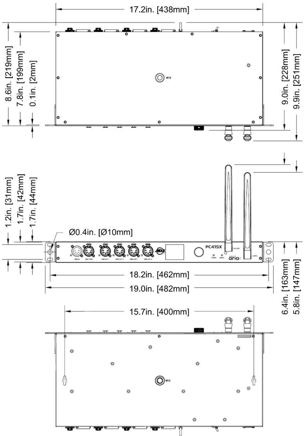
OPTIONAL ACCESSORIES
| ORDER CODE | ITEM | |
| US EU | ||
| PCC415 13210000 | 96 PC415X DMX RELAY CENTER | |
| TOU027 N/A Tour Link 5P10 | ||
| Additional Cable Lengths Available | ||

FCC STATEMENT
This device complies with Part 15 of the FCC Rules. Operation is subject to the following two conditions: (1) this device may not cause harmful interference, and (2) this device must accept any interference received, including interference that may cause undesired operation.
FCC RADIO FREQUENCY INTERFERENCE WARNINGS & INSTRUCTIONS
This product has been tested and found to comply with the limits as per Part 15 of the FCC Rules. These limits are designed to provide reasonable protection against harmful interference in a residential installation. This device uses and can radiate radio frequency energy and, if not installed and used in accordance with the included instructions, may cause harmful interference to radio communications. However, there is no guarantee that interference will not occur in a particular installation. If this device does cause harmful interference to radio or television reception, which can be determined by turning the device off and on, the user is encouraged to try to correct the interference by one or more of the following methods:
- Reorient or relocate the device.
- Increase the separation between the device and the receiver.
- Connect the device to an electrical outlet on a circuit different from which the radio receiver is connected.
- Consult the dealer or an experienced radio/TV technician for help.
Energy Saving Matters (EuP 2009/125/EC)
Saving electric energy is a key to help protecting the environment. Please turn off all electrical products when they are not in use. To avoid power consumption in idle mode, disconnect all electrical equipment from power when not in use. Thank you!

text_image
ADJ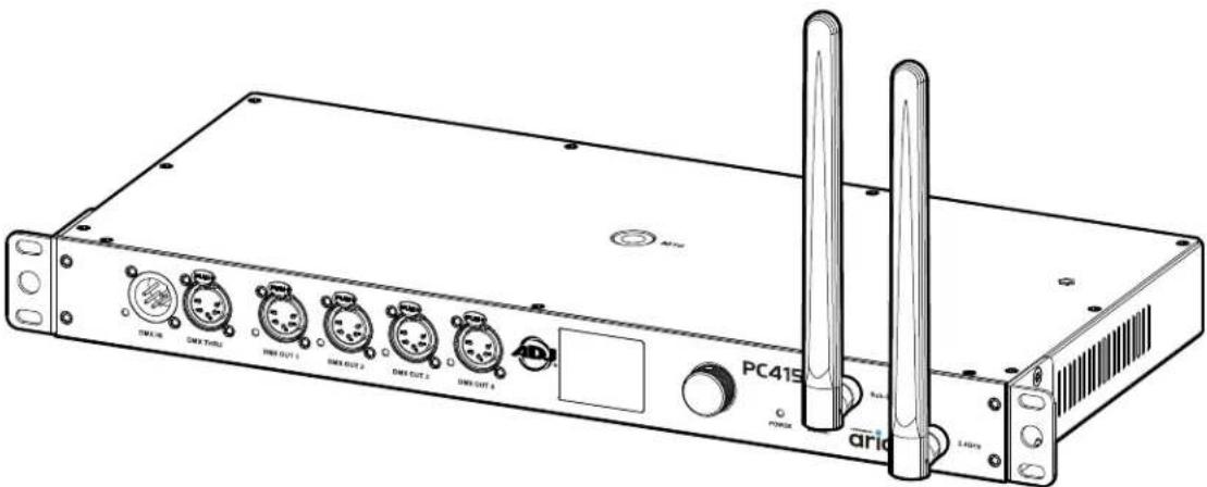
text_image
PC415 arid P0000 TIFL18 DINX THRU DINX OUT 1 DINX OUT 2 DINX OUT 3 DINX OUT 4 DC DC DC DC DC DC DC DC DC DC DC DC DC DC DC DC DC DC DC DC DC DC DC DC DC DC DC DC DC DC DC DC DC DC DC DC DC DC DC DC DC DC DC DC DC DC DC DC DC DC PC415PC4I5X
©2025 ADJ Products, LLC all rights reserved. Information, specifications, diagrams, images, and instructions herein are subject to change without notice. ADJ Products, LLC logo and identifying product names and numbers herein are trademarks of ADJ Products, LLC. Copyright protection claimed includes all forms and matters of copyrightable materials and information now allowed by statutory or judicial law or hereinafter granted. Product names used in this document may be trademarks or registered trademarks of their respective companies and are hereby acknowledged. All non-ADJ Products, LLC brands and product names are trademarks or registered trademarks of their respective companies.
ADJ Products, LLC and all affiliated companies hereby disclaim any and all liabilities for property, equipment, building, and electrical damages, injuries to any persons, and direct or indirect economic loss associated with the use or reliance of any information contained within this document, and/or as a result of the improper, unsafe, insufficient and negligent assembly, installation, rigging, and operation of this product.
ADJ Supply Europe B.V.
ADJ Supply Europe B.V.
natural_image
Line drawing of a server rack with multiple ports and connectors (no text or symbols)DIRECTIVES D'INSTALLATION
INSTALLATION SUR STRUCTURE
natural_image
Silhouette of a group of people with an upward arrow in the background (no text or symbols)MENU DU SYSTÈME
natural_image
Close-up of two black electrical plug connectors with gold pins, shown from side to top (no text or symbols visible)TERMINAISON DE LIGNE :
Important: Ensure that the Aria firmware is up to date on each fixture before performing a Fixture firmware update.
Specifications and documentation subject to change without notice.