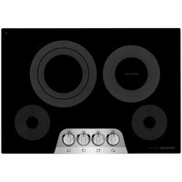
GCCE3049SS - Cooker FRIGIDAIRE - Free user manual and instructions
Find the device manual for free GCCE3049SS FRIGIDAIRE in PDF.


User questions about GCCE3049SS FRIGIDAIRE
0 question about this device. Answer the ones you know or ask your own.
Ask a new question about this device
Download the instructions for your Cooker in PDF format for free! Find your manual GCCE3049SS - FRIGIDAIRE and take your electronic device back in hand. On this page are published all the documents necessary for the use of your device. GCCE3049SS by FRIGIDAIRE.
USER MANUAL GCCE3049SS FRIGIDAIRE
ELECTRIC COOKTOP INSTALLATION INSTRUCTIONS
Canada Unit
ED States INSTALLATION AND SERVICE MUST BE PERFORMED BY A QUALIFIED INSTALLER.

IMPORTANT: SAVE FOR LOCAL ELECTRICAL INSPECTOR'S USE. READ AND SAVE THESE INSTRUCTIONS FOR FUTURE REFERENCE.
WARNING FOR YOUR SAFETY: Do not store or use gasoline or other flammable vapors and liquids in the vicinity of this or any other appliance.

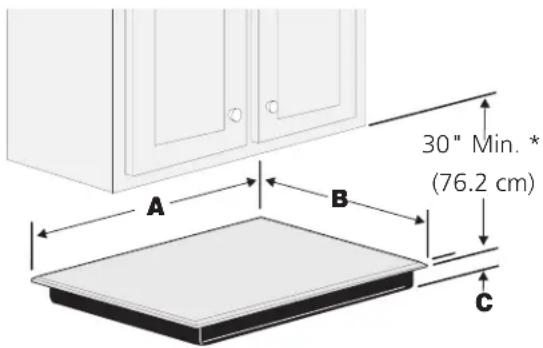
Cooktop Dimensions
text_image
30" Min. * (76.2 cm) A B CCooktop Cutout Dimensions
IMPORTANT INSTALLATION-INFORMATION
- All electric cooktops run off a single phase, three-wire or four-wire cable, 240/208 volt, 60 hertz, AC only electrical supply with ground.
- Please note minimum distances between cooktop and adjacent and overhead cabinetry is 30" (76.2cm).
text_image
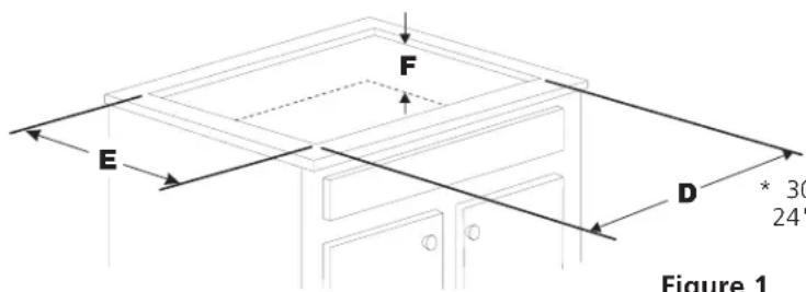
E F D * 30 24" Figure 1* 30" (76.2 cm) min. for unprotected cabinet 24" (61 cm) min. for protected surface
Figure 1
| MODEL A. LENGTH B. WIDTH C. DEPTH | CUTOUT DIMENSIONSD. LENGTH E. WIDTHMIN. MAX. MIN. MAX. | F. DEPTH BELOW COOKTOP* | ||||||
| 30" | 30^5/8" (77.8 cm) | 21^3/8" (54.4 cm) | 2^5/8" (6.7 cm) | 28^1/2" (72.4 cm) | 29^7/8" (75.9 cm) | 19^5/8" (49.9 cm) | 20^1/2" (52.1 cm) | 5"(12.7 cm) |
| 36" | 36^3/4" (93.5 cm) | 21^3/8" (54.4 cm) | 2^5/8" (6.7 cm) | 33^7/8" (86.0 cm) | 36^1/8" (91.8 cm) | 19^1/8" (48.6 cm) | 20^1/2" (52.1 cm) | 5"(12.7 cm) |
All dimensions are in inches (cm).
Only some models are available in Canada.
* Allow 2" (5 cm) space below cooktop to clear the electric cable and allow for installation of the junction box on the wall at the back of the cooktop.
P/N A01705002 (18/09) Rev. B
English – pages 1-8
Français – pages 9-16
ELECTRIC COOKTOP INSTALLATION INSTRUCTIONS
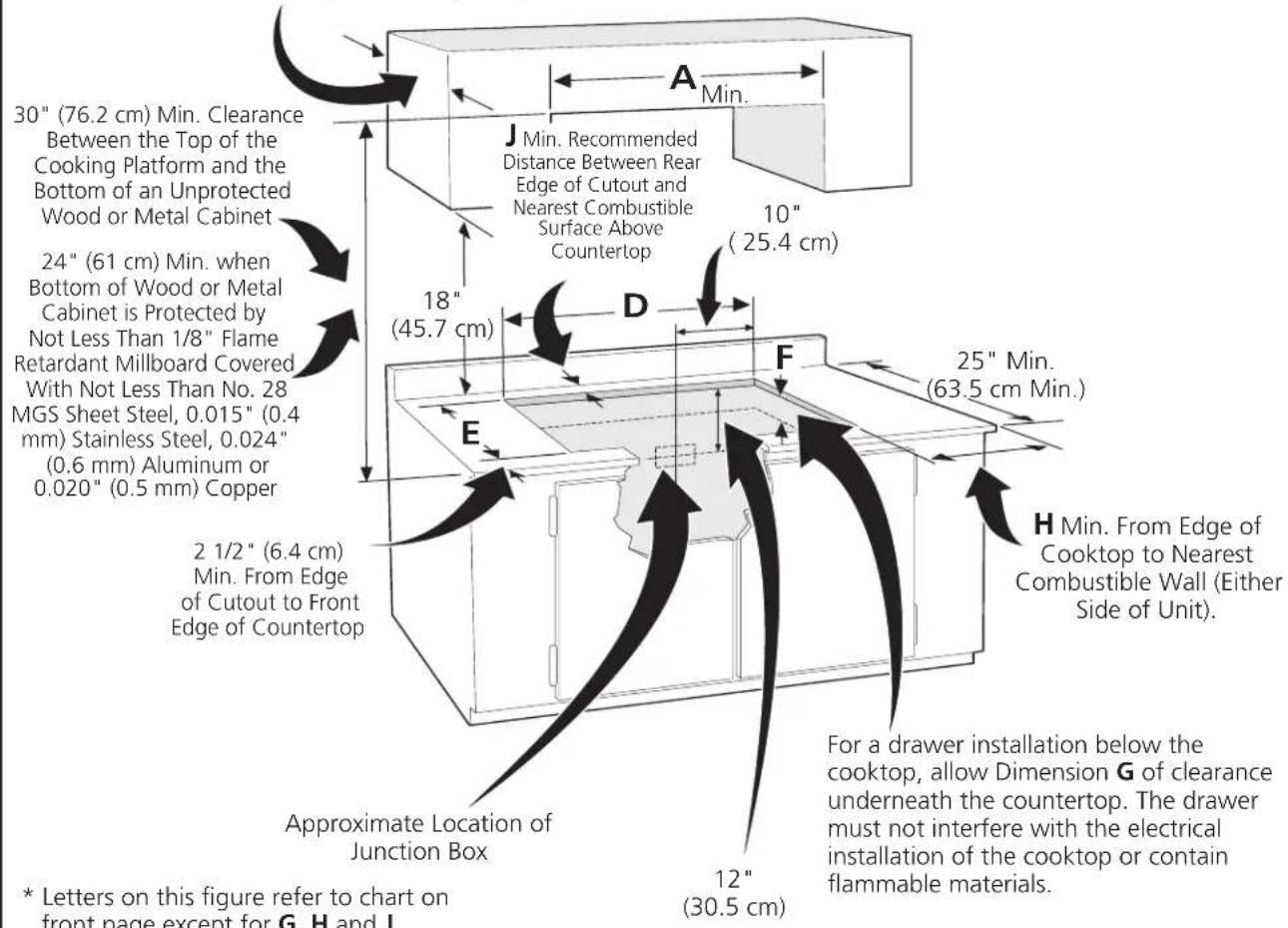
Overhead Cabinet Should Not Exceed a Maximum Depth of 13" (33 cm)
text_image
30" (76.2 cm) Min. Clearance Between the Top of the Cooking Platform and the Bottom of an Unprotected Wood or Metal Cabinet 24" (61 cm) Min. when Bottom of Wood or Metal Cabinet is Protected by Not Less Than 1/8" Flame Retardant Millboard Covered With Not Less Than No. 28 MGS Sheet Steel, 0.015" (0.4 mm) Stainless Steel, 0.024" (0.6 mm) Aluminum or 0.020" (0.5 mm) Copper 18" (45.7 cm) 10" (25.4 cm) 2 1/2" (6.4 cm) Min. From Edge of Cutout to Front Edge of Countertop Approximate Location of Junction Box 12" (30.5 cm) A J Min. Recommended Distance Between Rear Edge of Cutout and Nearest Combustible Surface Above Countertop D F E H Min. From Edge of Cooktop to Nearest Combustible Wall (Either Side of Unit). For a drawer installation below the cooktop, allow Dimension G of clearance underneath the countertop. The drawer must not interfere with the electrical installation of the cooktop or contain flammable materials. * Letters on this figure refer to chart on front page except for G, H and J.CAUTION To eliminate the risk of burns or fire by reaching over heated surfaces, cabinet storage space located above the cooktop should be avoided. If cabinet storage is provided, risk can be reduced by installing a range hood that projects horizontally a minimum of 5" (12.7 cm) beyond the bottom of the cabinets.
| MODELGHJ | |||
| 30" | 4"(10.2 cm) | 7 12 "(19.1 cm) | 2"(5.1 cm) |
| 36" | 4"(10.2 cm) | 7 12 "(19.1 cm) | 2"(5.1 cm) |
Figure 2 – COUNTERTOP CUTOUT OPENING
Important Notes to the Installer
- Read all instructions contained in these installation instructions before installing the cooktop.
- Remove all packing material before connecting the electrical supply to the cooktop.
- Observe all governing codes and ordinances.
- Be sure to leave these instructions with the consumer.
Important Note to the Consumer
Keep these instructions with your owner's guide for future reference.
ELECTRIC COOKTOP INSTALLATION INSTRUCTIONS
IMPORTANT SAFETY INSTRUCTIONS
- Be sure your cooktop is installed and grounded properly by a qualified installer or service technician.
- These cooktops must be electrically grounded in accordance with local codes or, in their absence, with the National Electrical Code ANSI/NFPA No. 70—latest edition in the United States, or with CSA Standard C22.1, Canadian Electrical Code, Part 1, in Canada.
WARNING The electrical power to the cooktop must be shut off while line connections are being made. Failure to do so could result in serious injury or death.
Provide Electrical Connection
Install the junction box under the cabinet and run 120/240 or 120/208 Volt, AC wire from the main circuit panel. DO NOT connect the wire to the circuit panel at this time.
Electrical Requirements
This appliance must be supplied with the proper voltage and frequency, and connected to an individual, properly grounded branch circuit, protected by a circuit breaker or fuse. A circuit breaker or fuse is required by your appliance. The circuit breaker or fuse amperage recommended for your appliance is 40A or 50A.
Observe all governing codes and local ordinances
- A 3-wire or 4-wire single phase 120/240 or 120/208 Volt, 60 Hz AC only electrical supply is required on a separate circuit fused on both sides of the line (red and black wires). A time-delay fuse or circuit breaker is recommended. DO NOT fuse neutral (white wire). Only certain cooktop models may be installed over certain built-in electric oven models. Approved cooktops and built-in ovens are listed by the MFG ID number (see the insert sheet included in the literature package).
NOTE: Wire sizes and connections must conform with the fuse size and rating of the appliance in accordance with the American National Electrical Code ANSI/NFPA No. 70-latest edition, or with Canadian CSA Standard C22.1, Canadian Electrical Code, Part 1, and local codes and ordinances.
WARNING An extension cord should not be used with this appliance. Such use may result in a fire, electrical shock, or other personal injury.
- The flexible armored cable extending from the appliance should be connected directly to the junction box. The junction box should be located as shown in Figure 1 or Figure 2 and with as much slack as possible remaining in the cable between the box and the appliance, so it can be moved if servicing is ever necessary.
- A suitable strain relief must be provided to attach the flexible armored cable to the junction box.
Unpacking Instructions
(Models with Ceramic-Glass Smoothtop Only)
- Leave corner supports on cooktop until completion of Electrical Connection.
- Be sure the bottle of cleaner conditioner packed in the literature bag is left where the user can find it easily. It is important that the ceramic-glass smoothtop be pretreated before use.
text_image
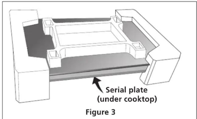
Serial plate (under cooktop) Figure 3Electrical Connection
It is the responsibility and obligation of the consumer to contact a qualified installer to assure that the electrical installation is adequate and is in conformance with the National Electrical Code ANSI/NFPA No. 70-latest edition, or with CSA Standard C22.1, Canadian Electrical Code, Part 1, and local codes and ordinances.
! WARNING Risk of electrical shock (Failure to heed this warning may result in electrocution or other serious injury.) This appliance is equipped with copper lead wire. If connection is made to aluminum house wiring, use only connectors that are approved for joining copper and aluminum wire in accordance with the National Electrical Code and local code and ordinances. When installing connectors having screws which bear directly on the steel and/or aluminum flexible conduit, do no tighten screws sufficiently to damage the flexible conduit. Do not over bend or excessively distort flexible conduit to avoid separation of convolutions en exposure of internal wires.
Electrical ground is required on this appliance.
ELECTRIC COOKTOP INSTALLATION INSTRUCTIONS
This appliance is manufactured with a frame connected green (or bare copper) ground wire.
WARNING DO NOT ground to a gas supply pipe. DO NOT connect to electrical power supply until appliance is permanently grounded. Connect the ground wire before turning on the power.
If your appliance is not equipped with a white neutral conductor:
Connect only to a 3-wire, 120/240V power supply; the neutral conductor is not required for the operation of the appliance. The potential at the power supply electrical connections shall be 150V to ground or less.
NOTE TO ELECTRICIAN: The armored cable leads supplied with the appliance are UL-recognized for connection to larger gauge household wiring. The insulation of the leads is rated at temperatures much higher than temperature rating of household wiring. The current carrying capacity of the conductor is governed by the temperature rating of the insulation around the wire, rather than the wire gauge alone.
RISK OF ELECTRIC SHOCK: Grounding through the neutral conductor is prohibited for new branch-circuit installations (1996 NEC); mobile homes; recreational vehicles; or in Canada, or in an area where local codes prohibit grounding through the neutral connector.
WARNING (If your appliance is equipped with a white neutral conductor.) This appliance is manufactured with a white neutral power supply and a frame connected copper wire. The frame is grounded by connection of grounding lead to neutral lead at the termination of the conduit, if used in USA, in a new branch circuit installation (1996 NEC), mobile home, recreational vehicles, where local code do not permit grounding trough the neutral (white) wire or in Canada, disconnect the white and green lead from each other and use ground lead to ground unit in accordance with local codes, connect neutral lead to branch circuit-neutral conductor in usual manner see Figure 6 or 7. If your appliance is to be connected to a 3 wire grounded junction box (US only), where local code permit connecting the appliance-grounding conductor to the neutral (white) see Figure 4 or 5.
Where local codes permit connecting the appliance-grounding conductor to the neutral (white) wire (USA only):
Your appliance has a 3-wire cable to be connected to a 3-wire grounded junction box (see figure 4):
- Disconnect the power supply.
- In the circuit breaker, fuse box or junction box: Connect appliance and power supply cable wires as shown in figure 4.

text_image
Cable from Power Supply Ground Wire Red Wires Black Wires Junction Box Ground Wire (Bare or Green Wire) U.L.-Listed Conduit Connector (or CSA listed) Cable from applianceFigure 4 – U.S.A. Only 3-WIRE GROUNDED JUNCTION BOX
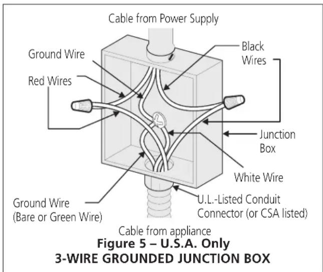
Your appliance has a 4-wire cable to be connected to a 3-wire grounded junction box (see figure 5):
- Disconnect the power supply.
- In the junction box:
Connect appliance and power supply cable wires as shown in Figure 5.
text_image
Cable from Power Supply Black Wires Ground Wire Red Wires Junction Box White Wire U.L.-Listed Conduit Connector (or CSA listed) Ground Wire (Bare or Green Wire) Cable from appliance Figure 5 – U.S.A. Only 3-WIRE GROUNDED JUNCTION BOXELECTRIC COOKTOP INSTALLATION INSTRUCTIONS
If the appliance is used in a new branch circuit installation (1996 NEC), mobile home, recreational vehicle, or where local codes DO NOT permit grounding through the neutral (white) wire, the appliance frame MUST NOT be connected to the neutral wire of the 4-wire electrical system.
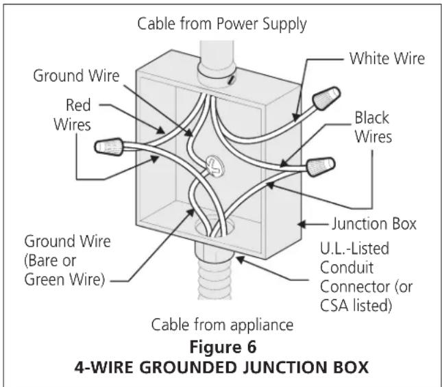
Your appliance has a 3-wire cable to be connected to a 4-wire grounded junction box (see figure 6):
- Disconnect the power supply.
- Separate the green (or bare copper) and white appliance cable wires.
- Cap the white wire from the power supply cable if a 3-wire appliance cable is supplied.
- In the circuit breaker, fuse box or junction box: Connect appliance and power supply cable wires as shown in figure 6.
text_image
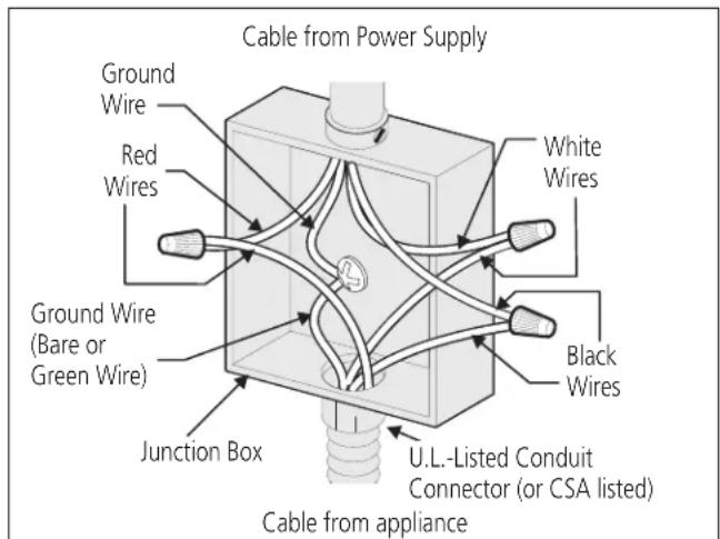
Cable from Power Supply White Wire Black Wires Ground Wire Red Wires Junction Box U.L.-Listed Conduit Connector (or CSA listed) Ground Wire (Bare or Green Wire) Cable from appliance Figure 6 4-WIRE GROUNDED JUNCTION BOXYour appliance has a 4-wire cable to be connected to a 4-wire grounded junction box (see figure 7):
- Disconnect the power supply.
- In the junction box:
Connect appliance and power supply cable wires as shown in Figure 7.
text_image
Cable from Power Supply Ground Wire Red Wires Ground Wire (Bare or Green Wire) Junction Box U.L.-Listed Conduit Connector (or CSA listed) White Wires Black Wires Cable from applianceFigure 7 4-WIRE GROUNDED JUNCTION BOX
ELECTRIC COOKTOP INSTALLATION INSTRUCTIONS
Cooktop Installation
1. All Ceramic-Glass Cooktops
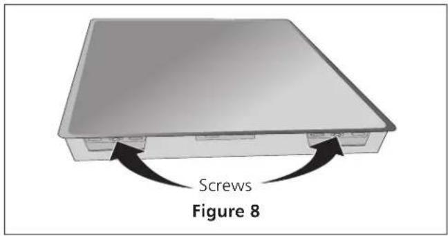
Visually inspect the cooktop for damage. Also make sure all cooktop screws are tight (see Figure 8).
text_image
Screws Figure 8Set the cooktop into the countertop cutout.
NOTE: Do not use caulking compound; cooktop should be removable for service when needed.
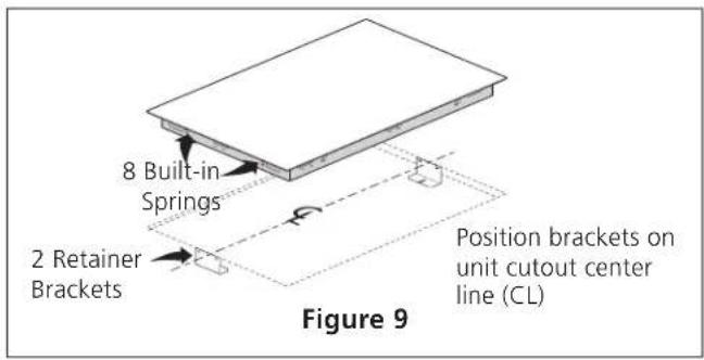
WARNING Do not remove the built in springs on the edges of the cooktop. These springs center the cooktop in the space provided. The cooktop must be centered to prevent excess heat buildup that may result in heat damage or fire (see Figure 9).
text_image
8 Built-in Springs 2 Retainer Brackets Position brackets on unit cutout center line (CL) Figure 9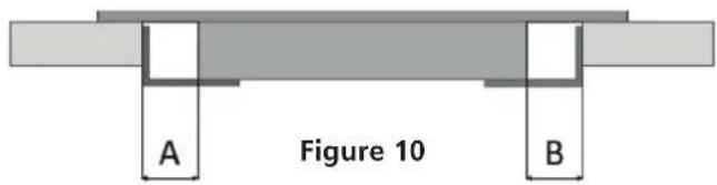
text_image
Figure 10 A BDuring the installation with wide cutout, make sure the cooktop is centered. A and B gap should have the same dimensions. The elongated holes on the bottoms of the installation brackets are made to fit every cutout.
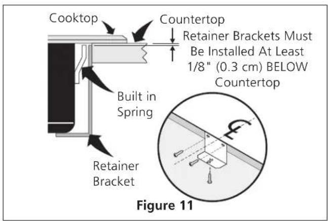
The retainer brackets MUST be installed, to meet local codes or, in their absence, with the National Electrical Code ANSI/NFPA No. 70—latest edition, or with CSA Standard C22.1, Canadian Electrical Code, Part 1 (see Figure 11).
text_image
Cooktop Countertop Retainer Brackets Must Be Installed At Least 1/8" (0.3 cm) BELOW Countertop Built in Spring Retainer Bracket Figure 11ELECTRIC COOKTOP INSTALLATION INSTRUCTIONS
Granite countertop installation
If installing this cooktop into a granite countertop, make sure to perform the following operations:
- Use a Dow Corning heat proof silicone tube (glass top silicone grey, black or white). This part is available also as spare part, article number 73219-1780.
- Tape the brackets (by the top of the bracket) exactly where they are supposed to be according to the installation instructions (use duct tape, or similar adhesive tape).
- Lift the brackets and apply a generous amount of silicone on the lip portion of the countertop.
- Apply enough silicone such that there will be excess silicone that will flow/push through all/each of the holes in the brackets.
- Apply the brackets to the silicone on the countertop, as specified in the diagram.
- Visually verify that the excess silicone has pushed through all/each of the holes in the bracket.
- Do not remove the excess silicone that has flowed/pushed through the bracket holes. Once cured, this excess silicone will provide additional support for the brackets.
- Allow to cure for the minimum time prescribed by the silicone glue manufacturer. You will find this information on the external surface of the silicone tube.
- Remove all the duct tape from the installation.
- Install the cooktop in place, as specified in the diagram, and secure with mounting screws.
Checking Operation
Refer to the Owner's Guide for operation.
CAUTION
Do not touch cooktop glass or elements.
They may be hot enough to burn.
Model and Serial Number Location
The serial plate is located under the cooktop or in the burner box and can be seen by lifting up the main top of unit.
When ordering parts for or making inquires about your cooktop, always be sure to include the model and serial numbers and a lot number or letter from the serial plate on your cooktop.
Before You Call for Service
Read the Avoid Service Checklist and operating instructions in your Owner's Guide. It may save you time and expense. The list includes common occurrences that are not the result of defective workmanship or materials in this appliance.
Refer to the warranty in your Owner's Guide for our service phone number and address. Please call or write if you have inquiries about your product and/or need to order parts.
ELECTRIC COOKTOP INSTALLATION INSTRUCTIONS
For typical under counter installation of an electric built-in oven see Figure below.
Only certain cooktop models may be installed over certain built-in electric oven models.
Approved cooktops and built-in ovens are listed by the MFG ID number and product code (see the insert sheet included in the literature package and cooktop installation instructions for dimensions).
Note 1: 4" x 4" (10.2cm X 10.2cm) opening to route armored cable from cooktop to junction box.
WARNING
To reduce the risk of personal injury and tipping of the wall oven, the wall oven must be secured to the cabinet(s) by mounting brackets.
208/240 Volt junction box for built-in oven.
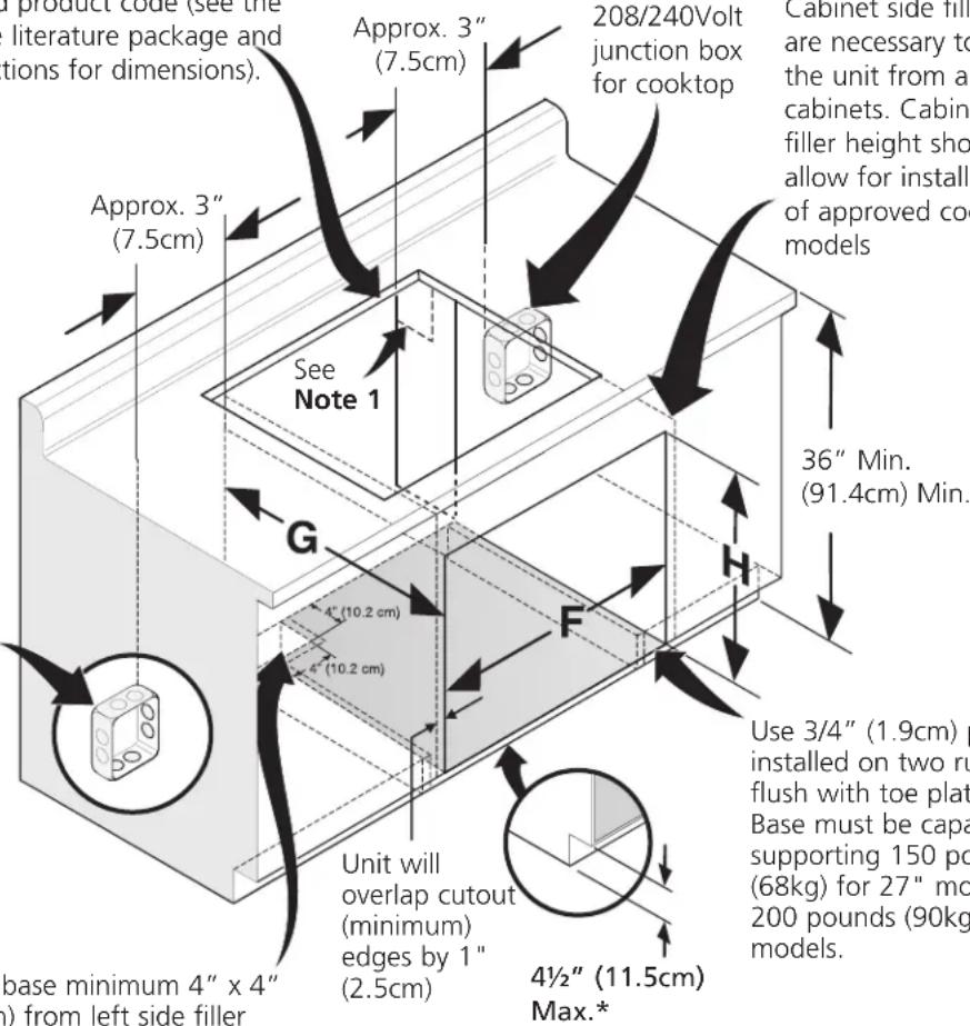
text_image
Product code (see the literature package and tions for dimensions). Approx. 3" (7.5cm) 208/240Volt junction box for cooktop Cabinet side fill are necessary to the unit from a cabinets. Cabin filler height should allow for install of approved co models Approx. 3" (7.5cm) See Note 1 36" Min. (91.4cm) Min. G 4" (10.2 cm) F Use 3/4" (1.9cm) p installed on two ru flush with toe plate. Base must be capa supporting 150 pc (68kg) for 27" mo 200 pounds (90kg) models. Unit will overlap cutout (minimum) edges by 1" (2.5cm) 4½" (11.5cm) Max.* base minimum 4" x 4" ) from left side fillerCut an opening in wood base minimum 4" x 4" (10.2 X 10.2cm), 2" (5cm) from left side filler panel, to route armoured cable to junction box.
Use 3/4" (1.9cm) plywood, installed on two runners, flush with toe plate. Base must be capable of supporting 150 pounds (68kg) for 27" models and 200 pounds (90kg) for 30" models.
* If no cooktop is installed directly over the oven unit, 5" (12.7cm) maximum is allowed above the floor.
| CUTOUT DIMENSIONS | |||
| F. WIDTH G. DEPTH H. HEIGHT | |||
| 27" (68.6cm) Wall Oven | 24 18 " (63.2cm) Min. 25 14 " (64.1cm) Max. | 23 12 " (59.7cm) Min. | 27 14 " (69.2cm) Min. 28 14 " (71.8cm) Max. |
| 30" (76.2cm) Wall Oven | 28 12 " (72.4cm) Min. 29" (73.7cm) Max. | 23 12 " (59.7cm) Min. | 27 14 " (69.2cm) Min. 28 14 " (71.8cm) Max. |
TYPICAL UNDER COUNTER INSTALLATION OF A SINGLE ELECTRIC BUILT-IN OVEN WITH AN ELECTRIC COOKTOP MOUNTED ABOVE
INSTRUCTIONS D'INSTALLATION POUR PLAQUE DE CUISSON ÉLECTRIQUE
Canada États-Unis

UN INSTALLATEUR QUALIFIÉ DOIT EFFECTUER L'INSTALLATION ET LE SERVICE.
IMPORTANT: CONSERVEZ CES INSTRUCTIONS POUR LES INSPECTEURS LOCAUX. LISEZ CES INSTRUCTIONS ET CONSERVEZ-LES POUR RÉFÉRENCES ULTÉRIEURES.
text_image
E F D * Mini Mini Figure 1INSTRUCTIONS DE SÉCURITÉ IMPORTANTES
P/N A01705002 (18/09) Rev. B
English – pages 1-8
Français – pages 9-16