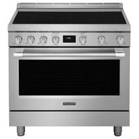
PCFI3670SS - Cooker FRIGIDAIRE - Free user manual and instructions
Find the device manual for free PCFI3670SS FRIGIDAIRE in PDF.


User questions about PCFI3670SS FRIGIDAIRE
0 question about this device. Answer the ones you know or ask your own.
Ask a new question about this device
Download the instructions for your Cooker in PDF format for free! Find your manual PCFI3670SS - FRIGIDAIRE and take your electronic device back in hand. On this page are published all the documents necessary for the use of your device. PCFI3670SS by FRIGIDAIRE.
USER MANUAL PCFI3670SS FRIGIDAIRE
INSTALLATION INSTRUCTIONS 36" INDUCTION RANGE
INSTALLATION AND SERVICE MUST BE PERFORMED BY A QUALIFIED INSTALLER.
IMPORTANT: SAVE FOR LOCAL ELECTRICAL INSPECTOR'S USE. READ AND SAVE THESE INSTRUCTIONS FOR FUTURE REFERENCE.
WARNING
FOR YOUR SAFETY: Do not store or use gasoline or other flammable vapors or liquids near this or any other appliance.
Table of Contents
IMPORTANT SAFETY INSTRUCTIONS...... 2
Product Dimensions 3
Cabinet clearances.... 4
Location of the grounded outlet.... 4
Installing the backguard 5
Installing the front/side skirting.... 5
Installing the door handle 6
Island installation....7
Unpacking, moving and positioning the range 7
Electrical connection 8
Wall and floor attachment.... 10
Door removal.... 12
Important Notes to the Installer
- Read all instructions contained in these installation instructions before installing the range.
- Remove all packing materials from the oven and the drawer compartments before connecting the electrical supply to the range.
- Observe all governing codes and ordinances. Be sure to leave these instructions with the consumer.
Important Note to the Customer
Keep these instructions with your owner's guide for future reference.
36" INDUCTION RANGE INSTALLATION INSTRUCTIONS
IMPORTANT SAFETY INSTRUCTIONS
This manual contains important safety symbols and instructions. Please pay attention to these symbols and follow all instructions given.
WARNING
This symbol will help alert you to situations that may cause serious injury death or property damage.
CAUTION
This symbol will help alert you to situations that may cause injury or property damage.
CAUTION
Cold temperatures can damage the electronic control. When using the appliance for the first time, or when the appliance has not been used for a long time, make sure that the unit has been in temperatures above 32^ F ( 0^ C) for at least 3 hours before turning on the power to the appliance.
- Make sure your range is installed and grounded properly by a qualified installer or service technician.
- This range must be electrically grounded in accordance with local codes or, in their absence, with the National Electrical Code ANSI/NFPA No. 70—latest edition in United States or with CSA Standard C22.1, Canadian Electrical Code, Part 1 in Canada.
- The installation of appliances designed for manufactured (mobile) home installation must conform with Manufactured Home Construction and Safety Standard, title 24CFR, part 3280 [Formerly the Federal Standard for Mobile Home Construction and Safety, title 24, HUD (part 280)] or when such standard is not applicable, the Standard for Manufactured Home Installation 1982 (Manufactured Home Sites, Communities and Setups), ANSI Z225.1/NFPA 501A-latest edition, or with local codes in United States and with CAN/CSA-Z240 MH in Canada.
- Make sure the wall coverings around the range can withstand the heat generated by the range.
- Before installing the range in an area covered with linoleum or any other synthetic floor covering, make sure the floor covering can withstand heat at least 90^ (32.2°C) above room temperature without shrinking, warping or discoloring. Do not install the range over carpeting unless you place an insulating pad or sheet of 1/4'' (0.64 cm) thick plywood between the range and carpeting.
WARNING
Never leave children alone or unattended in the area where an appliance is in use. As children grow, teach them the proper, safe use of all appliances. Never leave the oven door open when the range is unattended.
WARNING
Stepping, leaning or sitting on the door or drawer of this range can result in serious injuries and can also cause damage to the range.
- Do not store items of interest to children in the cabinets above the range. Children could be seriously burned if they climb on the range to reach items.
- To eliminate the risk of burns or fire by reaching over hot surface units, cabinet storage space above the surface unit should be avoided. If cabinet storage is to be provided, the risk can be reduced by installing a range hood that projects a minimum of 5 inches horizontally beyond the bottom of the cabinet.
- Do not use the oven as a storage space. This creates a potentially hazardous situation.
- Never use your range for warming or heating the room. Prolonged use of the range without adequate ventilation can be dangerous.
- Do not store or use gasoline or other flammable vapors and liquids near this or any other appliance. Explosions or fires could result.
- Reset all controls to the "OFF" position after using a programmable timing operation.
36" INDUCTION RANGE INSTALLATION INSTRUCTIONS
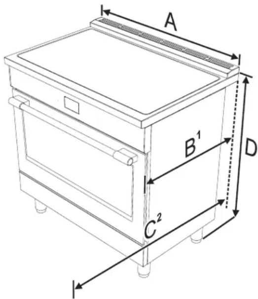
Product Dimensions
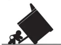
WARNING
natural_image
Silhouette of a person pushing a large object on a horizontal line (no text or symbols)Tip Over Hazard
• A child or adult could tip the range over and be killed.
• Install the anti-tip device on the floor or wall as per the installation instructions.
- Engage the range with the anti-tip device as per the installation instructions.
- Ensure the anti-tip device is re-engaged when the range is moved.
- Do not operate the range without the anti-tip device in place and engaged.
- Failure to follow these instructions can result in death or serious burns to children and adults.
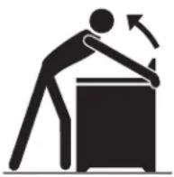
To check if the anti-tip bracket is installed properly, use both arms and grasp the back edge of the range. Carefully attempt to tilt the range forward. When properly installed, the range should not tilt forward.
Refer to the anti-tip bracket installation instructions supplied with your range for proper installation.
text_image
A B¹ C² DA 912.4 mm 35 15/16"
B1 min: 627 mm min: 24 11/16" max: 631 mm max: 24 13/16"
C2 1116 mm 43 15/16"
D min: 893.8 mm min: 35 3/16" max: 944.6 mm max: 37 3/16"
-
Measurement B varies according to the model: the minimum is obtained without the rear spacers (see "Island installation") and the maximum is obtained for traditional installation (slot-in installation - with the rear spacers).
-
Measurement C refers to the open door.
Cabinet clearances
The side cabinet depth (clearance F) must match the front edge of the range side panel:
E 914 mm 36"
F 603 mm 23" 3/4
G 178 mm 7"
Location of the grounded outlet
Clearance J can have the following values:
- J = 30'' / 762 mm minimum clearance between the top of the cooking surface and the bottom of an unprotected wood or metal cabinet.
- J = 24" / 610 mm minimum when the bottom of wood or metal cabinet is protected by not less than 1/4-inch-thick flame-retardant millboard covered with not less than No. 28 MSG sheet steel, 0.015-inch-thick stainless steel, 0.024-inch-thick aluminum, or 0.020-inch-thick copper. Clearances from non-combustible materials are not part of the ANSI Z21.1 scope and are not certified by CSA. Clearances of less than 30" should be approved by the local codes and/or by the local authority having jurisdiction.
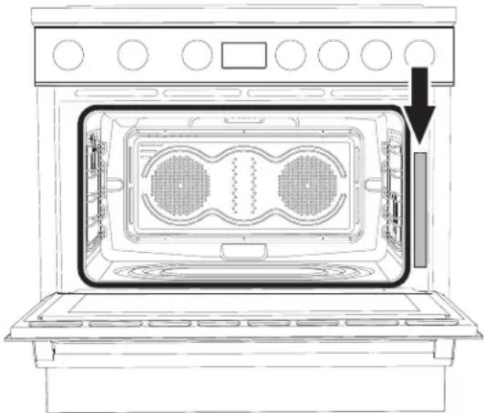
The grounded outlet should be located in the highlighted area in the image above. This area must have the following measures:
D Min: 11" 7/8 Min: 300 mm
Min: 11" 7/8 Min: 300 mm
Max: 24" 2/8 Max: 614 mm
Min: 2" Min: 51 mm
Max: 9" 7/8 Max: 250 mm
36" INDUCTION RANGE INSTALLATION INSTRUCTIONS
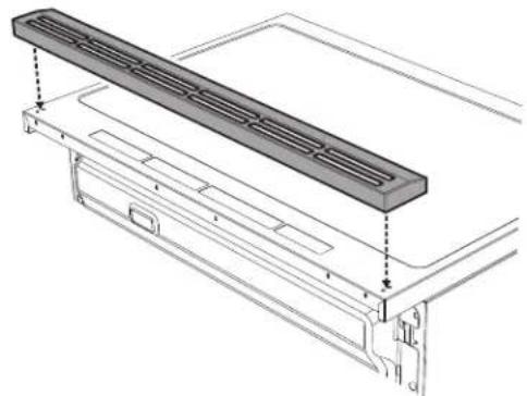
Installing the backguard
The backguard provided is an integral part of the appliance; it must always be positioned and secured correctly on the cooktop.
- Position the backguard on the top.
natural_image
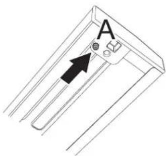
Technical line drawing of a mechanical component with a rectangular plate and mounting bracket (no text or symbols)- Make sure that you align the pins (A) of the back-guard with the holes (B) on the cooktop.
text_image
A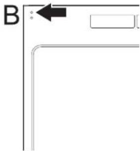
natural_image
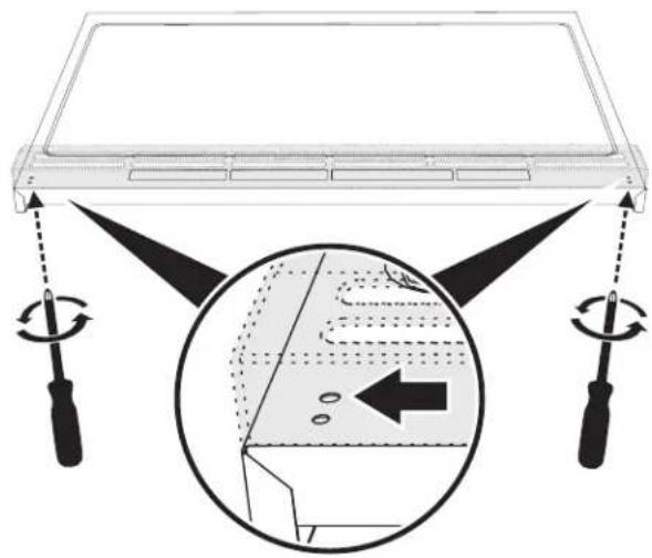
Pure geometric lines forming an L-shape with a black arrow pointing to a rectangle (no text or symbols)- Secure the backguard to the top by the tightening the screws.
natural_image
Diagram showing a device with rotating arms and a magnified inset highlighting internal components (no text or symbols)Installing the front/side skirting
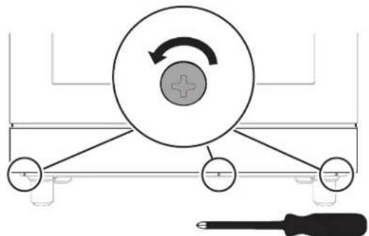
The front skirting must always be correctly positioned and secured to the appliance.
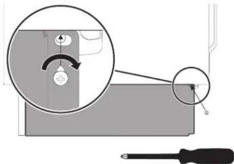
- Use a screwdriver to remove the front screws.
natural_image
Diagram of a mechanical or electrical setup with a circular component and connected components, including a screwdriver (no text or symbols present)-
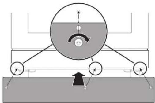
Position the front skirting at the bottom of the appliance and line up the holes on the side of the skirting with the holes on the base of the appliance.
-
Fasten the front skirting to the appliance using the screws that were previously removed.
text_image
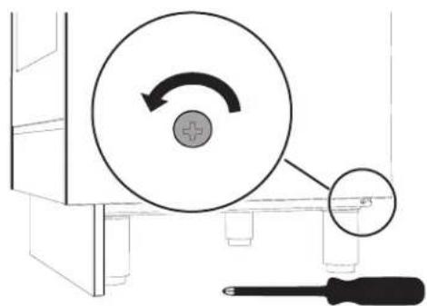
Diagram illustrating a mechanical or fluid system with labeled components and directional arrows, likely representing a physical or engineering setup.- After the front skirting has been installed, the side skirting can be fastened correctly to the appliance. Use a screwdriver to remove the side screws.
text_image
Diagram showing a screwdriver interacting with a circular component, indicating rotation or adjustment of a mechanical part.36" INDUCTION RANGE INSTALLATION INSTRUCTIONS
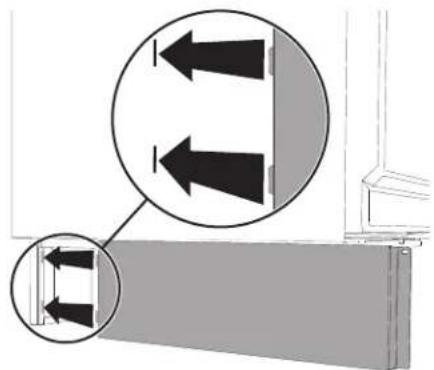
- Insert the tabs on the side skirting into the slots on the back of the front skirting.
natural_image
Diagram showing two arrows pointing upward on a wall, with a magnified inset highlighting the structure (no text or symbols present)-
Line up the hole on the side skirting with the rear hole on the base of the appliance.
-
Fasten the side skirting to the appliance using the screw that was previously removed.
text_image
Diagram showing a mechanical component with a magnified inset highlighting a curved arrow and a screwdriver, likely illustrating a turning or positioning process.- Repeat the procedure for the other side skirting section.
Installing the door handle
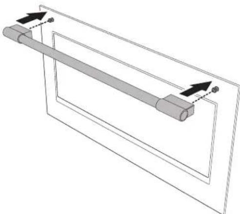
The door handle provided comes unattached to the appliance and must be secured to the oven door during the installation.
- Position the handle to the attaching pins of the oven door.
natural_image
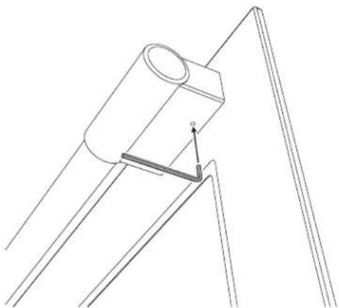
Pure mechanical diagram showing a lever and guide mechanism without any text, numbers, or symbols- Secure the handle by tightening the screws underneath both its ends. Use the provided 3/32" hex Allen key.
natural_image
Pure technical line drawing of a mechanical assembly without any text, numbers, or symbols36" INDUCTION RANGE INSTALLATION INSTRUCTIONS
Island installation
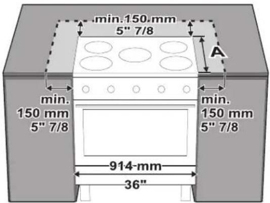
If the appliance is installed as an island:
- Unscrew the screws indicated.
- Remove the spacers (C).
- Insert the screws that were previously removed into their seats.

text_image
C 1 2Keep a minimum clearance of 5 7/8" (150 mm) between the appliance and the other furnishings or decorative elements according to the diagram below.
text_image
min.150 mm 5" 7/8 A min. 150 mm 5" 7/8 min. 150 mm 5" 7/8 914-mm 36"The side cabinet depth (clearance A) must match the front edge of the range side panel:
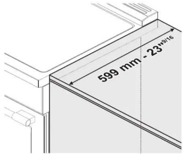
text_image
599 mm - 23"9/16Unpacking, moving and positioning the range
CAUTION
This unit is designed as a cooking
appliance. For safety reasons, never use it for warming the room or as a space heater.
- It is recommended that the front kick panel, the backguard and oven racks be removed to facilitate handling. This will reduce the weight for moving.
- When positioning the appliance during installation, do not use the door handle to lift or move the appliance.
- The appliance can be moved with a hand dolly or with a clamp lift truck (not with a fork lift truck) only if it is still packaged.
- Wear gloves to avoid cutting fingers on sharp edges during installation.
- Remove the outer carton and packing material from the shipping base.
- Before moving range ensure legs are installed completely.
- Due to its weight, after removing the packing material, move it with the help of a second person.
- The floor under the legs should be protected (wood, strips, carpet, paneling, etc.) before pushing the unit into position.
36" INDUCTION RANGE INSTALLATION INSTRUCTIONS
- The anti-tip device must be installed, and the electrical connection should be made before the range is placed in its final position.
- Legs should be installed near to where the appliance will be used as they are not secure for long transit. Keep the unit raised so that the legs can be screwed into their couplings, then lower the range gently to prevent the legs and mounting hardware from being subject to any undue strain.
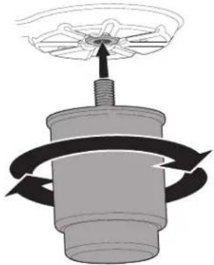
natural_image
Diagram of a mechanical device with rotating arrows indicating motion (no text or symbols)NOTE: First insert the front feet and then the rear ones.
The following is the correct order of installation and positioning:
- Install and adjust the legs.
- Assemble and fix the anti-tip bracket to the floor or wall.
- Connect the plug to the grounded outlet.
- Move the range to its final position.
The adjustment range of the screw is 2 inches (50.8 mm).
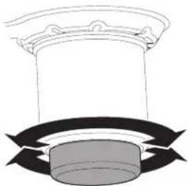
natural_image
Diagram of a column with a circular base and curved arrows indicating rotation or flow (no text or symbols)The appliance must sit level on the floor to ensure stability:
- Screw or unscrew the bottom part of the foot until the appliance is stable and level on the floor.
NOTE: this appliance must only use the specific leveling legs provided by the manufacturer.
Electrical connection
WARNING

Electrical shock hazard
- This appliance is equipped with a four-prong grounding plug for your protection against electric shock and should be plugged directly into a properly grounded receptacle. Do not cut or remove the grounding prong from this plug.
- The grounding prong must be plugged into a matching grounding type receptacle and connected to a correctly polarized 240-Volt circuit. If there is any doubt as to whether the wall receptacle is properly grounded, have it checked by a qualified electrician.
Failure to do any of the above could result in a fire, personal injury or electrical shock.
36" INDUCTION RANGE INSTALLATION INSTRUCTIONS
WARNING

Electrical shock hazard
- For personal safety, this appliance must be properly grounded. For maximum safety, the power cord must be securely connected to an electrical outlet or junction box that is the correct voltage, is correctly polarized and properly grounded, and protected by a circuit breaker in accordance with local codes.
- It is the personal responsibility of the consumer to have the appropriate outlet or junction box with the correct, properly grounded wall receptacle installed by a qualified electrician. It is the responsibility and obligation of the consumer to contact a qualified installer to ensure that the electrical installation is suitable and in conformance with all local codes and ordinances.
This range is equipped with a factory-connected power cord. The cord must be connected to a grounded 120/240 volt or 120/208 volt outlet. If no outlet is available, have one installed by a qualified electrician.
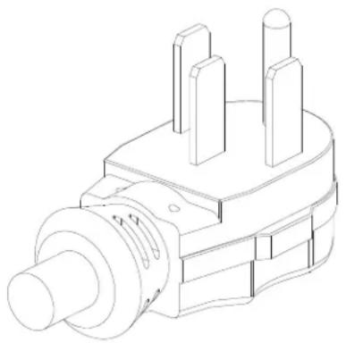
natural_image
Technical line drawing of a mechanical component with three protrusions and a central shaft (no text or symbols)CAUTION
Do not use multiple outlets, exten-
sion cords or adapters.
See the rating plate for technical specifications. The rating plate is visibly located on the right side of the oven door frame.
This ID plate must never be removed.
natural_image
Line drawing of an oven interior with ventilation grilles and a door, showing no text or symbols36" INDUCTION RANGE INSTALLATION INSTRUCTIONS
Wall and floor attachment
! WARNING

Electrical shock hazard
- Use extreme caution when drilling holes in the wall or floor. There may be concealed electrical wiring behind the wall or under the floor.
- Identify the location of the electrical circuits that could be affected by the installation of the anti-tip device, then turn off power to these circuits.
- Failure to follow these instructions may result in electrical shock or other personal injury.
- Contact a qualified installer or contractor to determine the proper method for drilling holes through the wall or floor material (such as ceramic tile, hardwood, etc.)
- Failure to follow these instructions may result in damage to wall or floor coverings.
CAUTION
WARNING
Visually check from the inside of the drawer that the wall/floor-mounted bracket is inserted into the appropriate lateral hook (left side).
Positioning the bracket using the template:
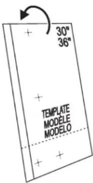
- Choose the correct side of the template, based on the model.
text_image
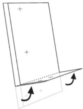
30" 36" + + TEMPLATE MODELE MODELO + +- Based on the model, fold the template sheet following the horizontal dashed line,.
natural_image
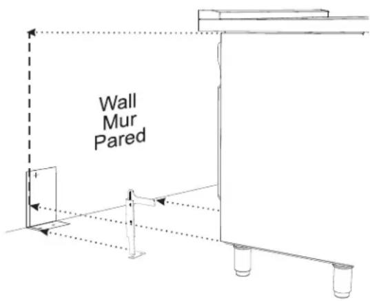
Simple line drawing of a rectangular block with plus signs and an arrow indicating rotation, no text or symbols present.- Place the template so that the thick vertical line drawn on it is aligned with the edge of the left side of the appliance.
text_image
Wall Mur Pared- Mark the location of the screw holes, to wall or to floor depending of how you want to fix the bracket.
- Fix the anti-tip bracket.
36" INDUCTION RANGE INSTALLATION INSTRUCTIONS
Installing the anti-tip bracket:
-
Ensure that the electrical connection is in the correct position.
-
Assemble the bracket.
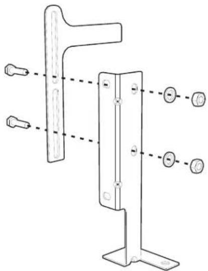
natural_image
Technical line drawing of a metal bracket with mounting holes and dashed alignment lines (no text or symbols)- Align the base of the hook of the bracket with the base on the slot of the rear wall fastening bracket. Align the base of the fastening bracket with the floor and tighten the screws to fix the measurements.
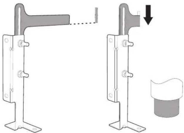
natural_image
Mechanical assembly diagram showing two metal frame assemblies with a handle and a separate cylindrical component (no text or symbols)- For wall mounting, follow the steps 5, 6, 9 and 10. For floor mounting follow the to steps 7, 8, 9 and 10.
NOTE: The wall attachment is recommended if the appliance is placed against a wall. Floor attachment is recommended in case of island installation.
- Use the specified distance from the side of the appliance to the bracket holes.
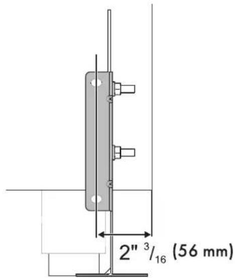
text_image
2"³/₁₆ (56 mm)- Move the bracket to the wall and fix with the two washers and screws. A qualified technician must verify the suitability of the materials in accordance with the type and condition of the wall.
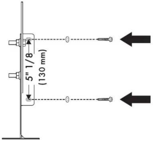
text_image
5" 1/8 (130 mm)36" INDUCTION RANGE INSTALLATION INSTRUCTIONS
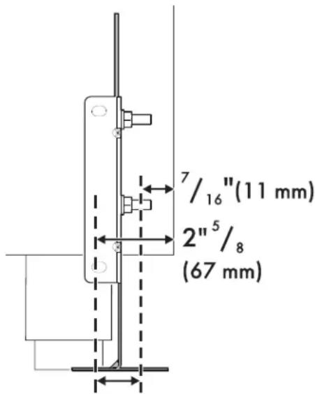
- Use the following distances for the distance from the side of the appliance to the bracket holes.
text_image
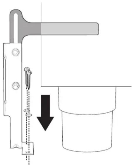
7/16"(11 mm) 2"5/8 (67 mm)- After having positioned and leveled the appliance, move the bracket close to the rear of the appliance and anchor it to the floor using the two washers and screws. A qualified technician must verify the suitability of the materials in accordance with the type and condition of the floor.
natural_image
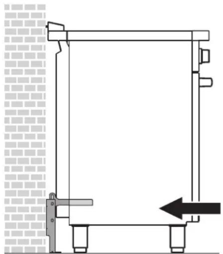
Diagram of a mechanical assembly with a tool and pin, showing a downward arrow indicating motion (no text or symbols present)- Push the cooker towards the wall, and at the same time, insert the bracket in the plate that is fastened to the rear of the appliance.
natural_image
Technical line drawing of a structural frame with supports and a directional arrow (no text or symbols)WARNING The rear vent trim has 3/16" (5 mm) standoffs to keep the appliance slightly away from the back wall. Do not remove or tamper with standoffs due to potential temperature issues.
- Check for proper installation and use of the anti-tip bracket. Carefully tip the range forward by pulling it from the back to ensure that the anti-tip bracket engages the range leg and prevents tip-over. The range should not move more than 1" (2.5cm).
Door removal
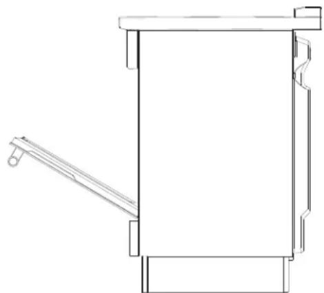
It is not necessary to remove the door in order to install the range, but is an added convenience. Refer to the Use and Care Guide for the oven door removal instructions.
natural_image
Technical line drawing of a mechanical device with lever and base (no text or symbols)INSTALLATION INSTRUCTIONS CUISINIÈRE À INDUCTION 36"
L'INSTALLATION ET L'ENTRETIEN DOIVENT ÊTRE EFFECTUÉS PAR UN INSTAL- LATEUR QUALIFIÉ.
natural_image
Silhouette of a person pushing a large object on a horizontal line (no text or symbols)text_image
A B¹ C² DA 912.4 mm 35 15/16"
B1 min: 627 mm min: 24 11/16" max: 631 mm max: 24 13/16"
C2 1116 mm 43 15/16"
D min: 893.8 mm min: 35 3/16" max: 944.6 mm max: 37 3/16"
text_image
H I G F E J K I GE 914 mm 36"
F 603 mm 23" 3/4
G 178 mm 7"
natural_image
Technical line drawing of a mechanical component with a rectangular plate and mounting bracket (no text or symbols)natural_image
Pure geometric lines forming an L-shape with a black arrow pointing to a rectangle (no text or symbols)natural_image
Diagram showing a device with rotating arms and a magnified inset highlighting a component detail (no text or symbols)natural_image
Diagram of a mechanical or electrical setup with a circular component and three connected components, plus an arrow indicating rotation (no text or symbols present)text_image
Technical diagram showing a mechanical or fluid system with rotating components and directional arrows, likely illustrating fluid flow or motion.text_image
Diagram showing a mechanical assembly with a rotating component and a screwdriver, labeled with angle 45°INSTRUCTIONS D'INSTALLATION CUISINIÈRE À INDUCTION 36"
natural_image
Diagram showing two arrows pointing upward on a wall, with a magnified inset highlighting the lower section (no text or symbols)text_image
Diagram showing a mechanical component with a magnified inset highlighting a curved arrow and a screwdriver, likely illustrating a turning or positioning process.natural_image
Pure mechanical diagram showing a lever and guide mechanism without any text, numbers, or symbolsnatural_image
Pure technical line drawing of a mechanical assembly without any text, numbers, or symbolsINSTRUCTIONS D'INSTALLATION CUISINIÈRE À INDUCTION 36"
natural_image
Diagram of a mechanical component with rotating arrows indicating motion (no text or symbols)natural_image
Diagram of a column with directional arrows indicating rotation or flow (no text or symbols)natural_image
Technical line drawing of a mechanical component with three protrusions and a central shaft (no text or symbols)natural_image
Line drawing of an oven with ventilation grilles and a door, showing internal structure without any text or symbolsINSTRUCTIONS D'INSTALLATION CUISINIÈRE À INDUCTION 36"
natural_image
Simple line drawing of a rectangular object with plus signs and an arrow indicating rotation, no text or symbols present.text_image
Wall Mur Parednatural_image
Technical line drawing of a metal bracket with mounting holes and dashed alignment lines (no text or symbols)natural_image
Diagram showing two mechanical components with a dashed line indicating alignment or dissection, and a separate cylindrical component (no text or symbols present)natural_image
Diagram of a mechanical assembly with a tool and pin, showing a downward arrow indicating a process or alignment (no text or symbols present)natural_image
Pure architectural line drawing of a vertical structure with horizontal supports and a black arrow indicating direction (no text or symbols)natural_image
Technical line drawing of a mechanical device with lever and base plate (no text or symbols)natural_image
Silhouette of a person pushing a large object on a pole (no text or symbols)Peligro de vuelco
text_image
A B¹ C² DA 912.4 mm 35 15/16"
B1 min: 627 mm min: 24 11/16" max: 631 mm max: 24 13/16"
C2 1116 mm 43 15/16"
D min: 893.8 mm min: 35 3/16" max: 944.6 mm max: 37 3/16"
text_image
H I G F E J K I GE 914 mm 36"
F 603 mm 23" 3/4
G 178 mm 7"
H mín. 914 mm mín. 36"
natural_image
Technical line drawing of a mechanical component with a rectangular frame and mounting bracket (no text or symbols)natural_image
Pure geometric lines forming an L-shape with a black arrow pointing to a corner (no text or symbols)natural_image
Diagram showing a device with rotating arms and a magnified view of internal components (no text or symbols)text_image
Diagram illustrating a mechanical or electrical system with labeled components and directional arrows, including a screwdriver.text_image
Technical diagram showing a mechanical or fluid system with labeled components and directional arrows indicating flow or movement.text_image
Diagram showing a screwdriver interacting with a circular component, labeled with rotation arrow and angle α3natural_image
Diagram showing two arrows pointing upward on a panel, with a magnified inset highlighting the structure (no text or symbols present)natural_image
Technical diagram showing a screwdriver inserted into a component with a magnified inset highlighting a curved mechanical feature (no text or symbols present)natural_image
Pure mechanical diagram showing a shaft and housing with directional arrows, no text or symbols presentnatural_image
Pure technical line drawing of a mechanical assembly without any text, numbers, or symbolstext_image
Diagram showing a vehicle with two wheels and two circular insets labeled 1 and 2, illustrating fluid flow or pressure measurement.natural_image
Diagram of a mechanical device with rotating components and a fan-like top (no text or symbols)natural_image
Diagram of a cylindrical object with curved arrows indicating rotation or flow, no text or symbols presentnatural_image
Technical line drawing of a mechanical component with three protrusions and a central shaft (no text or symbols)!ATENCIÓN
natural_image
Line drawing of an oven interior showing internal compartments and a door, with no text or symbols present.natural_image
Simple line drawing of a rectangular block with plus signs and an arrow indicating rotation, no text or symbols present.text_image
Wall Mur Parednatural_image
Technical line drawing of a metal bracket with mounting holes and dashed alignment lines (no text or symbols)natural_image
Mechanical assembly diagram showing two metal frame assemblies with a handle and a separate cylindrical component (no text or symbols)natural_image
Mechanical assembly diagram showing a tool inserted into a cylindrical component with a downward arrow indicating motion (no text or symbols present)914780103-A-392021