BCDV 4000 NG - Fridge Fors - Free user manual and instructions
Find the device manual for free BCDV 4000 NG Fors in PDF.

| Product type | Refrigerator |
| Brand | Fors |
| Model | BCDV 4000 NG |
| Power supply | 220-240 V / 50 Hz, 13 A, grounded plug |
| Temperature range | 2 °C to 12 °C (thermostat setting 1-7) |
| Optimal thermostat setting | Position 3-4 |
| Cooling system stop | Thermostat position 0 |
| Defrosting | Automatic, water drained and evaporated in compressor compartment |
| Internal lighting | Neon tube or LED depending on model, replaceable with identical parts |
| Canopy lighting | Present on some models, neon or LED |
| Door lock | On models with hinged doors, located at the top of the door |
| Thermometer | Digital with LR44 batteries, replacement every 2-3 years |
| Required ventilation distances | At least 50 mm behind and above the cabinet |
| Refrigerant type | R290/R600a (flammable) |
| Condenser maintenance | Cleaning 2 to 4 times per year with a vacuum cleaner with a brush |
| Reversible door | Yes, on some models, procedure described in the manual |
| Repairs | Must be carried out by a professional |
| Spare parts | Original, available from the dealer |
| Serial number | On the rating plate inside the appliance |
| European directives | LVD 2014/35/EU, EMC 2014/30/EU, RoHS 2011/65/EC |
| Construction materials | Asbestos-free and CFC-free, compressor oil without PCB |
Frequently Asked Questions - BCDV 4000 NG Fors
User questions about BCDV 4000 NG Fors
0 question about this device. Answer the ones you know or ask your own.
Ask a new question about this device
Download the instructions for your Fridge in PDF format for free! Find your manual BCDV 4000 NG - Fors and take your electronic device back in hand. On this page are published all the documents necessary for the use of your device. BCDV 4000 NG by Fors.
USER MANUAL BCDV 4000 NG Fors
natural_image
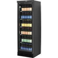
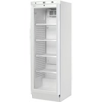
Three exterior view of a modern, empty refrigerator with glass doors and side shelves (no visible text or symbols)Instruction manual
Bedienungsanleitung
Mode d'emploi
Important Instructions:
The appliances mentioned in this document are only intended for preservation and cooling of beverages in bottles and cans.
Read the manual In order to obtain full benefit of the appliance.
It is the user's responsibility to utilize the appliance according to the instructions.
Contact the dealer immediately in case of any defects.
The appliance is only for indoor use.
The appliance should be placed in a dry sufficiently ventilated room.
The appliance should not be placed near a source of heat or direct sunlight.
The appliance should not be placed near a ventilation or air condition system.
Note that all electrical appliances can cause danger.
Do not store explosives such as gas, petrol, ether or similar substances in the appliance.
Asbestos nor CFC have been used in the production of the appliance.
The oil in the compressor does not contain PCB.
- THIS APPLIANCE MUST ALWAYS HAVE AN EARTHED PLUG!
- AT REPAIR ALWAYS UNPLUG THE APPLIANCE!
- ONLY FOR APPLIANCES WITH REFRIGERANT R290/R600a!
This appliance contains a flammable refrigerant, so make sure of good ventilation around the appliance.
Do not use mechanical devices when defrosting, this can cause leakage of the cooling system.
Do not use electrical appliances inside the refrigerated storage compartment.
Any repair of the appliance should be carried out by a skilled technician (EN 60335-2-89: 2010).
Unpacking and Installation:
Remove the packing and check that the cabinet has no transport damage.
Any transport damages should be reported to the transport company and noted on the delivery note.
When building-in ensure a distance of at least 50 mm behind the appliance and above the appliance.
Make sure that the air intake at the bottom panel is not blocked.
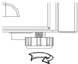
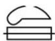
➢ Place the appliance in a level position for correct functioning. This can be achieved by adjusting the adjustable feet:
natural_image
Pure mechanical assembly diagram showing a spring-loaded component and a curved arrow indicating rotation (no text or symbols)Electrical Connections
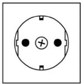
The appliance is intended for 220-240 V/50 Hz. The connection should be effected to an accessible socket.
This appliance should have extra protection according to the power regulations. This is also the case when replacing an existing appliance which does not have the extra protection.
Always use a 3 pin plug. The lead with green/yellow insulation should be earthed (marked ⊕).
In all other cases an authorized electrician can tell you how to get the extra protection of the appliance. In case there is no extra protection in the building, the Board of Electricity recommends that an electrician installs a PFI or HPFI switch (contact breaker).
natural_image
Simple circular diagram with three black dots and a central plus sign, no text or symbols present.230 V\~ 50 Hz
13A
The appliance should be connected to an 13A protected socket.
natural_image
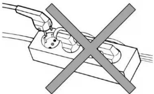
Pure electrical circuit lines without any symbolsThe appliance should not be connected to a multipoled distribution socket.
Start-up the Appliance
Before taking the appliance into use it is recommended to clean it – see section regarding maintenance.
Important!
In case the cabinet has been lying down during transport leave it standing up for 2 hours before switching it on.
Thermostat (Also see page 36)
The thermostat setting has a scale 1-7, corresponding to approx. 2-12 °C.
In most cases a setting of 3-4 will be optimum.
The cooling system can be switches off at 0.
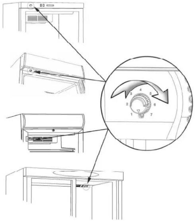
Depending on model the thermostat can be placed as follows:
- In top panel
- Under the canopy
- On the cover of the internal fan
Thermometer
All appliances are fitted with a thermometer.
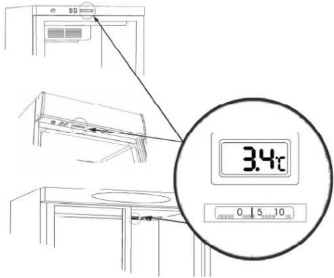
Depending on model the thermometer can be placed as follows:
- In top panel
- Under the canopy
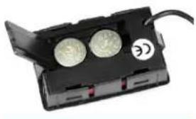
Digital thermometers are equipped with batteries that must be replaced every 2-3 years.
Open the flap on the back of the thermometer and replace the LR44 batteries:
natural_image
Close-up of a black battery pack with two circular buttons and a label showing '©' (no readable text or symbols beyond the label)Defrosting
The appliance has automatic defrost. Discharge water is led to evaporation in a drip tray placed in the compressor compartment.
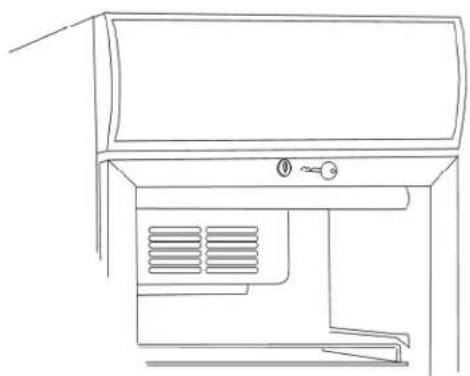
Lock
natural_image
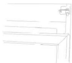
Line drawing of a cabinet or air conditioner unit with ventilation grilles and a handle (no text or symbols)The appliance with hinged door has a lock. The lock is placed at the top of the door.
Internal Light
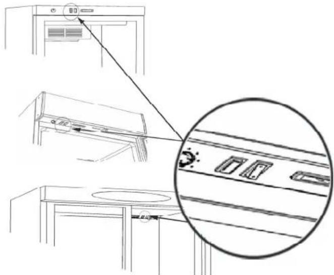
Appliance with internal light has a light switch. Depending on model this is placed as follows:
- In the top panel
- Under the canopy
- On the cover of the internal fan
Replacing the Light

REMEMBER to switch off the power before replacing the light!
Internal Light:
The internal fluorescent light is replaced by demounting the light cover. Replace the tube with an equivalent type.
The internal LED light should be replaced by an equivalent type. Contact your local supplier for original spare parts.
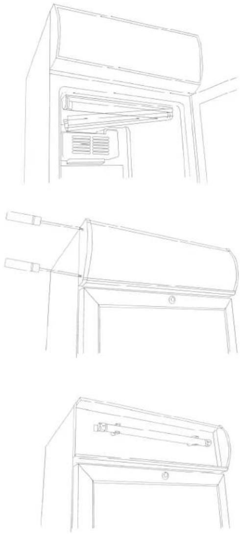
Canopy Light:
The external fluorescent light in the canopy is replaced by dismounting the end piece of the canopy. Pull the canopy plate to one side giving access to the fluorescent light. Replace it with an equivalent type.
The external LED light in the canopy is replaced in the same way.
Contact your local supplier for original spare parts.
Push carefully the canopy plate in place and remount the end piece of the canopy.
Door Reversal
Some models have reversible doors. Follow the below mentioned instructions for door reversal from right to left and vice versa.
This operation is easily done by carefully lying down the cabinet at its back or on a sack truck.
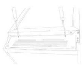
natural_image
Line drawing of a mechanical component with no visible text or symbols-
Remove the bottom panel
-
Remove the bottom hinge and the support fitting.
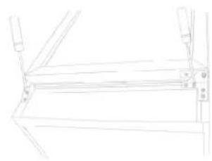
natural_image
Line drawing of a mechanical frame or bracket with no visible text, numbers, or symbols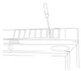
natural_image
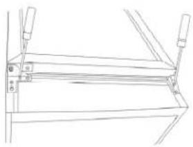
Line drawing of a mechanical device with a lever and base (no text or symbols)- Remove the top panel/canopy.
natural_image
Simple line drawing of a staircase with a vertical post (no text or symbols)- Lift the door and pull it approx. 10 cm down.
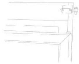
natural_image
Simple line drawing of a bench with a vertical pole and measurement scale (no text or symbols)
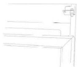
natural_image
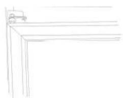
Simple line drawing of a cabinet or bench with a wall-mounted fixture (no text or symbols)-
Remove the top hinge pin.
-
Fit the hinge pin at the opposite side without tightening it.
natural_image
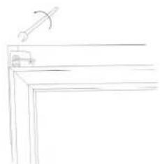
Simple line drawing of a corner structure with a small vehicle on top (no text or symbols)- Lift the door in place in the top hinge.
natural_image
Simple line drawing of a table with a handle and a small object on top (no text or symbols)
-
Tighten the top hinge pin.
-
Remove the bottom hinge pin and turn the bottom hinge 90 degrees.
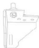
- Refit the bottom hinge pin to the bottom hinge which was turned.
natural_image
Technical line drawing of a mechanical frame or support structure (no text or symbols)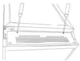
natural_image
Technical line drawing of a mechanical assembly with no visible text or symbols-
Fit the bottom hinge on the opposite side.
-
Refit the bottom panel.
natural_image
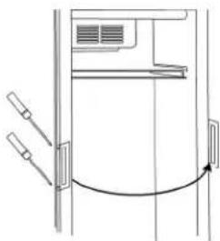
Diagram of a door with handlebars and an arrow indicating clockwise motion (no text or symbols)- Move the handle to the opposite hinge side.
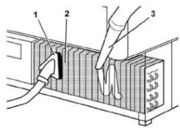
Maintenance
The appliance has a closed cooling system, which normally does not require any maintenance.

REMEMBER to switch off the power before cleaning the appliance!
However, it is recommended to clean the condenser 2-4 times a year by means of a brush or a vacuum cleaner. This can influence the energy consumption and the lifetime of the cabinet.
The appliance has automatic defrost. Discharge water is led to evaporation in a drip tray placed in the compressor compartment.

Service
In case of no cooling check failure in the power supply.
In case you are unable to find any failure, please contact your dealer.
You need to inform your dealer of the model number and serial number stated on the rating label normally placed inside on the right side of the cabinet.
Always use authorized technicians and original spare parts.

This device complies with the following EU Directives:
Low Voltage Directive (LVD) 2014/35/EU,
Electromagnetic Compatibility Directive (EMC) 2014/30/EU,
Restriction of Hazardous Substances (RoHS) Directive 2011/65/EC
Disposal
The disposal of old appliances should be done correctly in order to protect the environment.
Please observe the national regulations for disposal of old appliances.
DE
natural_image
Pure mechanical assembly diagram showing a spring-loaded component and a curved arrow indicating rotation (no text or symbols)Anschließen
natural_image
Simple circular diagram with three dots and a central cross, no text or symbols present230 V\~ 50 Hz
13A
natural_image
Diagram of a plug and socket with a crossed-out electrical symbol (no text or labels)natural_image
Black rectangular electronic device with two circular components and a label 'C' on its side (no readable text or symbols beyond the label)Abtauen
natural_image
Line drawing of a cabinet or air conditioner unit with ventilation grilles and a handle (no text or symbols)natural_image
Line drawing of a refrigerator interior showing the door, drawer, and seat (no text or symbols)Innenlicht:
Neon:
natural_image
Line drawing of a mechanical device with two protruding rods and a cylindrical component (no text or symbols)Licht im Canopy:
Neon:
natural_image
Line drawing of a cabinet or drawer with handle and base (no text or symbols)natural_image
Pure technical line drawing of a mechanical component without any text, numbers, or symbolsnatural_image
Line drawing of a mechanical frame or support structure with no visible text or symbolsnatural_image
Line drawing of a mechanical component with a tool inserted, no text or symbols present- Toppaneel abmontieren.
natural_image
Simple line drawing of a staircase with a vertical shelf and a horizontal shelf (no text or symbols)natural_image
Simple line drawing of a bench with a hanging stand (no text or symbols)natural_image
Simple line drawing of a staircase with a wall-mounted fixture (no text or symbols)natural_image
Simple line drawing of a corner joint or bracket (no text or symbols)natural_image
Simple line drawing of a corner table with a handle and angle marker (no text or symbols)natural_image
Pure technical line drawing of a mechanical assembly without any text, numbers, or symbolsnatural_image
Technical line drawing of a mechanical component with no visible text or symbolsnatural_image
Diagram of a door with attached sensors and a curved arrow indicating rotation (no text or symbols)Service
natural_image
Pure mechanical assembly diagram showing a spring-loaded component with a curved arrow indicating rotation (no text or symbols)natural_image
Simple circular diagram with three black dots and a central plus sign, no text or symbols present.230 V\~ 50 Hz
13A
natural_image
Diagram of a plug electrical socket with a crossed-out power line (no text or symbols)natural_image
Close-up of a black electronic device with two metallic coins and a label showing 'C' (no readable text or symbols on the device itself)Dégivrage
natural_image
Line drawing of a cabinet or air conditioner unit with ventilation grilles and a key (no text or symbols)natural_image
Line drawing of a mechanical device with two tools and a base plate (no text or symbols)natural_image
Pure technical line drawing of a mechanical assembly without any text, numbers, or symbolsnatural_image
Line drawing of a mechanical component with a tool inserted (no text or symbols)natural_image
Simple line drawing of a bench with a faucet on top (no text or symbols)natural_image
Simple line drawing of a bench with a vertical support (no text or symbols)natural_image
Simple line drawing of a staircase with a wall-mounted fixture (no text or symbols)natural_image
Simple line drawing of a corner bracket with a small vehicle on top (no text or symbols)natural_image
Simple line drawing of a desk lamp on a chair (no text or symbols)natural_image
Pure technical line drawing of a mechanical assembly without any text, numbers, or symbolsnatural_image
Line drawing of a mechanical component with internal slots and mounting brackets (no text or symbols)natural_image
Pure technical line drawing of a door or cabinet with no text, numbers, or symbolsService
natural_image
Pure mechanical assembly diagram without any text, numbers, or symbolsnatural_image
Pure electrical circuit lines without any symbolsnatural_image
Close-up of a black electronic component with two circular holes and a cable, no visible text or symbols.Sbrinamento
natural_image
Line drawing of a double door with ventilation slots and a handle (no text or symbols)natural_image
Line drawing of a mechanical component with no visible text or symbolsnatural_image
Line drawing of a metal frame structure with supports and measurement markings (no text or symbols)natural_image
Line drawing of a mechanical device with a pipette inserted into a slot (no text or symbols)natural_image
Simple line drawing of a bench with a wall-mounted device (no text or symbols)natural_image
Simple line drawing of a bench with a wall-mounted bracket (no text or symbols)natural_image
Simple line drawing of a bench with a wall-mounted fixture (no text or symbols)natural_image
Simple line drawing of a corner shelf with no text or symbolsnatural_image
Simple line drawing of a desk with a chair and a ladder (no text or symbols)natural_image
Technical line drawing of a mechanical frame assembly (no text or symbols)natural_image
Technical line drawing of a mechanical component with no visible text or symbolsnatural_image
Pure diagram of a door mechanism with no text, numbers, or symbolsServizio assistenza
Restriction of Hazardous Substances (RoHS) Directive 2011/65/EC
Smaltimento
BCV 4000 NG, BCDV 4000 NG, BCV 4000 WG, BCDV 4000 WG, BCDV 1500 WG
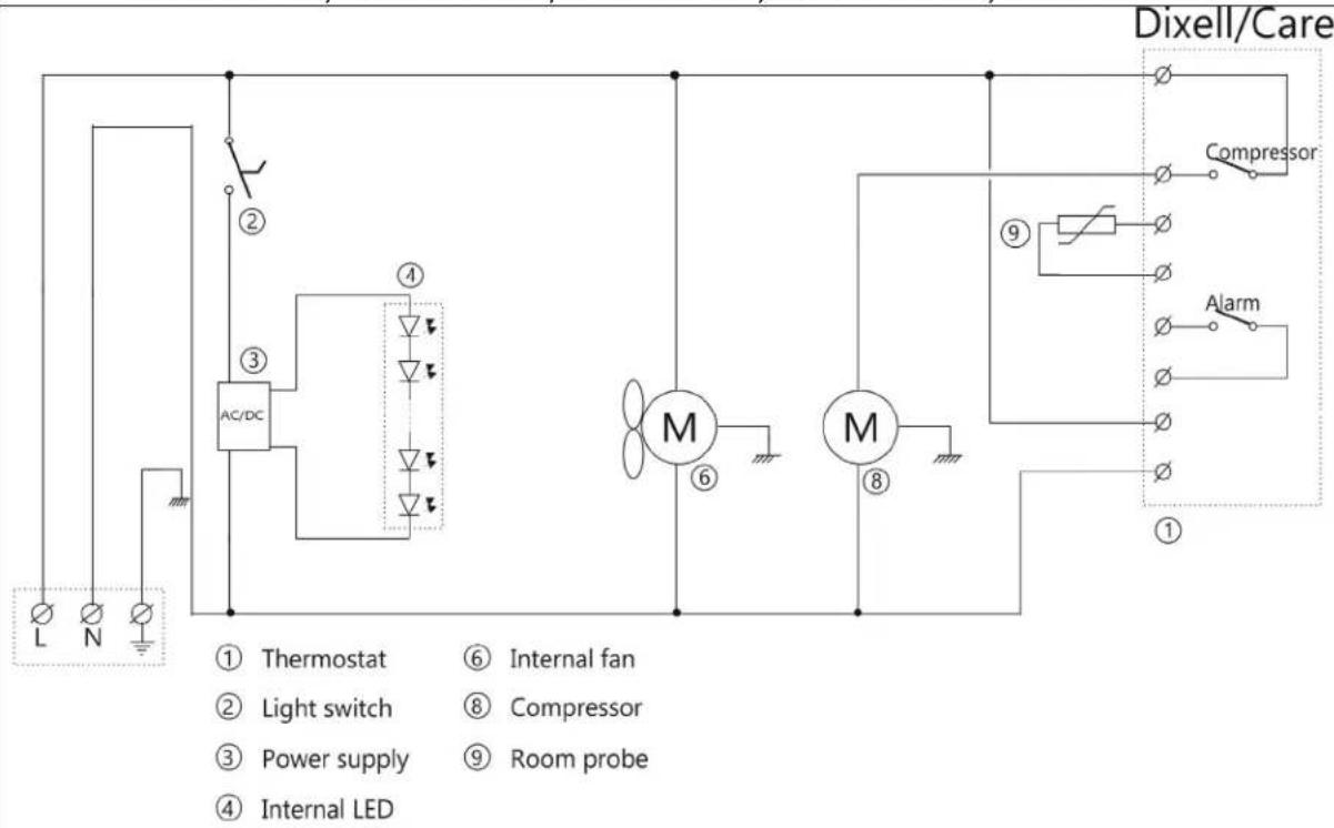
flowchart
graph TD
    A["Thermostat"] --> B["Light switch"]
    B --> C["Power supply"]
    C --> D["Room probe"]
    D --> E["Internal LED"]
    F["AC/DC"] --> G["①"]
    G --> H["②"]
    H --> I["③"]
    I --> J["④"]
    J --> K["M"]
    K --> L["⑥"]
    L --> M["M"]
    M --> N["⑧"]
    N --> O["⑨"]
    O --> P["Compressor"]
    P --> Q["Alarm"]
    Q --> R["Dixell/Care"]
SET


To display target set point, in programming mode it selects a parameter or confirm an operation
To start a manual defrost
In programming mode it browses the parameter codes or increases the displayed value In programming mode it browses the parameter codes or decreases the displayed value
KEYS COMBINATION
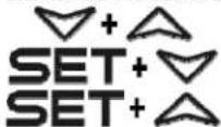
To lock or unlock the keyboard
To enter in programming mode
To return to room temperature display
| LED | MODE | FUNCTION |
| On | Compressor enabled | |
| Flashing | Anti short cycle delay enabled (AC parameter) | |
| On | Defrost in progress | |
| Flashing | Dripping in progress | |
| On | Fans output enabled | |
| Flashing | Fans delay after defrost | |
| On | Measurement unit | |
| Flashing | Programming mode | |
| On | Measurement unit | |
| Flashing | Programming mode |
HOW TO SEE THE SET POINT
- Push and immediately release the SET key, the set point will be showed;
- Push and immediately release the SET key or wait about 5s to return to normal visualisation.
HOW TO CHANGE THE SETPOINT
- Push the SET key for more than 2 seconds to change the Set point value;
- The value of the set point will be displayed and the "C" or "F" LED starts blinking;
- To change the Set value push the △ or ▽ arrows.
- To memorise the new set point value push the SET key again or wait 10s.
HOW TO START A MANUAL DEFROST
Push the DEF ✦ key for more than 2 seconds and a manual defrost will start
TO LOCK THE KEYBOARD
- Keep pressed for more than 3s the △ and ▽ keys.
- The "OF" message will be displayed and the keyboard will be locked. If a key is pressed more than 3s the "OF" message will be displayed.
TO UNLOCK THE KEYBOARD
Keep pressed together for more than 3s the ▲ and ▼ keys till the "on" message will be displayed.
ALARM SIGNALS
| Mess. | Cause | Outputs |
| "P1" | Room probe failure | Compressor output according to "Cy" e "Cn" |
| "P2" | Evaporator probe failure | Defrost end is timed |
| "HA" | Maximum temperature alarm | Outputs unchanged |
| "LA" | Minimum temperature alarm | Outputs unchanged |
| "EA" | External alarm | Outputs unchanged |
| "CA" | Serious external alarm | All outputs OFF |
| "dA" | Door Open | Compressor and fans restarts |
ALARM RECOVERY
Probe alarms P1" and "P2" start some seconds after the fault in the related probe; they automatically stop some seconds after the probe restarts normal operation. Check connections before replacing the probe. Temperature alarms "HA" and "LA" automatically stop as soon as the temperature returns to normal values.
Thermostat Carel
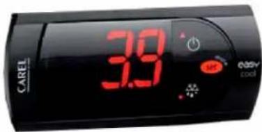
Display set temperature:

Press this key and the display will show the set temperature. Press the key again to return to normal reading.
Set new temperature:

Press this key and the display shows the set temperature.

Press this key to increase the set temperature.

Press this key to lower the set temperature.

Press this key to save the new settings. The display will flash with the new value and will then return to normal reading.
Alarm codes:
EO Flashing in the display: indicates that the cabinet sensor is defective. The cabinet will strive to keep the set temperature until it has been repaired.
HI Flashing in the display: indicates that the temperature is too high.
LO Flashing in the display: indicates that the temperature is too low.