
MVT30W9AST - Basket MIDEA - Free user manual and instructions
Find the device manual for free MVT30W9AST MIDEA in PDF.

| Product Type | Wall-mounted range hood |
| Brand | Midea |
| Model | MVT30W9AST |
| Power supply | 120 V, 60 Hz |
| Total power | 323 W |
| Motor power | 320 W |
| Lighting | 2 x 1.5 W LED |
| Airflow | 450 CFM (≈ 765 m³/h) |
| Noise level | ≤ 71 dB(A) |
| Exhaust duct diameter | 150 mm (6 in) |
| Installation type | External exhaust or recirculation (charcoal filter optional) |
| Material | Stainless steel |
| Grease filter | Aluminum, dishwasher-safe |
| Charcoal filter | Optional, replace every 4 months (ref. 12173000A00481) |
| Controls | Mechanical buttons (3 speeds, lighting, delayed shut-off, gesture control) |
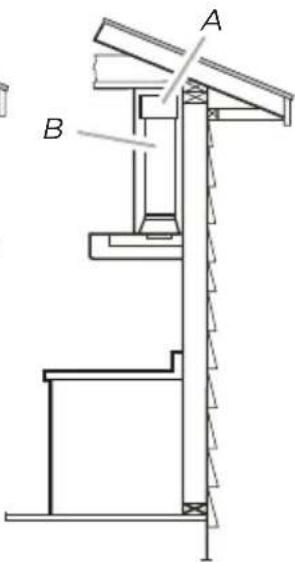
| Minimum height above cooking surface | 65.1 cm (25.6 in) |
| Maximum height above cooking surface | 74.9 cm (29.5 in) |
| Width | 75.8 cm (29.84 in) |
| Special features | Delayed shut-off 3 minutes, gesture control (proximity sensor) |
| Spare parts and repairability | Replaceable LED bulb (ref. 17473000000136), charcoal filter (ref. 12173000A00481) |
| Maintenance | Regular cleaning of grease filters, periodic replacement of charcoal filter |
| Safety | Mandatory grounding, automatic shut-off, grease fire protection |
Frequently Asked Questions - MVT30W9AST MIDEA
User questions about MVT30W9AST MIDEA
0 question about this device. Answer the ones you know or ask your own.
Ask a new question about this device
Download the instructions for your Basket in PDF format for free! Find your manual MVT30W9AST - MIDEA and take your electronic device back in hand. On this page are published all the documents necessary for the use of your device. MVT30W9AST by MIDEA.
USER MANUAL MVT30W9AST MIDEA
natural_image
Simple geometric diagram with a vertical rectangle and horizontal base, no text or symbols presentCooker Hood
USER MANUAL
MVT30W9AST
THANK YOU LETTER
Thank you for choosing Midea! Before using your new Midea product, please read this manual thoroughly to ensure that you know how to operate the features and functions that your new appliance offers in a safe way.
CONTENTS
THANK YOU LETTER 01
SAFETY INSTRUCTIONS 02
SPECIFICATIONS 05
PRODUCT OVERVIEW 06
PRODUCT INSTALLATION 11
OPERATION INSTRUCTIONS 14
CLEANING AND MAINTENANCE 15
TROUBLE SHOOTING 17
TRADEMARKS, COPYRIGHTS AND LEGAL STATEMENT 18
DISPOSAL AND RECYCLING 19
DATA PROTECTION NOTICE 20
SAFETY INSTRUCTIONS
Intended Use
The following safety guidelines are intended to prevent unforeseen risks or damage from unsafe or incorrect operation of the appliance. Please check the packaging and appliance on arrival to make sure everything is intact to ensure safe operation. If you find any damage, please contact the retailer or dealer. Please note modifications or alterations to the appliance are not allowed for your safety concern. Unintended use may cause hazards and loss of warranty claims.
Explanation of Symbols
 | DangerThis symbol indicates that there are dangers to the life and health of persons due to extremely flammable gas. |
 | Warning of electrical voltageThis symbol indicates that there is a danger to life and health of persons due to voltage. |
 | Warningwarning alerts you to situations that may cause serious body harm, death or property damage. |
 | Cautioncaution indicates a potentially hazardous situation which, if not avoided, may result in minor or moderate injury. |
 | AttentionThe signal word indicates important information (e.g. damage to property), but not danger. |
 | Observe instructionsThis symbol indicates that a service technician should only operate and maintain this appliance in accordance with the operating instructions. |
| [DD20] | ImportantImportant indicates installation, operation, maintenance or valuable information that is not hazard related. |
Read these operating instructions carefully and attentively before using/commissioning the unit and keep them in the immediate vicinity of the installation site or unit for later use!

WARNING
TO REDUCE THE RISK OF FIRE, ELECTRIC SHOCK OR INJURY TO PERSONS, OBSERVE THE FOLLOWING:
- Use this unit only in the manner intended by the manufacturer. If you have questions, contact the manufacturer at the address or telephone number listed in the warranty.
- Before servicing or cleaning unit, unplug and switch power off at service panel and lock service disconnecting means to prevent power from being switched on accidentally. When the service disconnecting means cannot be locked, securely fasten a prominent warning device, such as a tag, to the service panel.
- Installation work and electrical wiring must be done by qualified personnel in accordance with all applicable codes and standards, including fire-rated construction codes and standards.
- Sufficient air is needed for proper combustion and exhausting of gases through the flue (chimney) of fuel burning equipment to prevent backdrafting. Follow the heating equipment manufacturer's guidelines and safety standards such as those published by the National Fire Protection Association (NFPA) and the American Society for Heating, Refrigeration and Air Conditioning Engineers (ASHRAE) and the local code authorities.
- When cutting or drilling into wall or ceiling, do not damage electrical wiring and other hidden utilities.
- Ducted fans must always be vented to the outdoors.
- Do not use this unit with any solid-state speed control device.
• TO REDUCE THE RISK OF FIRE, USE ONLY METAL DUCTWORK. - This unit must be grounded. This appliance is equipped with a cord having a grounding wire with a grounding plug. The plug must be plugged into an outlet that is properly installed and grounded.
- Do not use an extension cord. If the power supply cord is too short, have a qualified electrician install an outlet near the appliance.
- When applicable local regulations comprise more restrictive installation and/or certification requirements, the aforementioned requirements prevail on those of this document and the installer agrees to conform to these at his own expense.
TO REDUCE THE RISK OF A RANGE TOP GREASE FIRE:
- Never leave surface units unattended at high settings. Boilovers cause smoking and greasy spillovers that may ignite. Heat oils slowly on low or medium settings.
- Always turn hood ON when cooking at high heat or when flambe-ing food (i.e.: Crêpes Suzette, Cherries Jubilee, Peppercorn Beef Flambé).
- Clean ventilating fans frequently. Grease should not be allowed to accumulate on fan, filters or in exhaust ducts.
- Use proper pan size. Always use cookware appropriate for the size of the surface element.
TO REDUCE THE RISK OF INJURY TO PERSONS IN THE EVENT OF A RANGE TOP GREASE FIRE, OBSERVE THE FOLLOWING\*:
- SMOTHER FLAMES with a close-fitting lid, cookie sheet or metal tray, then turn off the burner. BE CAREFUL TO PREVENT BURNS. IF THE FLAMES DO NOT GO OUT IMMEDIATELY, EVACUATE AND CALL THE FIRE DEPARTMENT.
- NEVER PICK UP A FLAMING PAN — You may be burned.
- DO NOT USE WATER, including wet dishcloths or towels —This could cause a violent steam explosion.
- Use an extinguisher ONLY if:
A. You own a Class ABC extinguisher and you know how to operate it.
B. The fire is small and contained in the area where it started.
C. The fire department has been called.
D. You can fight the fire with your back to an exit.
- Based on “Kitchen Fire Safety Tips” published by NFPA.

CAUTION
- For indoor use only.
- For general ventilating use only. Do not use to exhaust hazardous or explosive materials and vapors.
- To avoid motor bearing damage and noisy and/or unbalanced impeller, keep drywall spray, construction dust, etc. off power unit.
• Install the vent hood in a location away from strong drafts, such as windows, door, and strong HVAC vent for best performance. - The minimum hood distance above cooktop must not be less than 25-5/8". For best capture of cooking impurities, the bottom of the hood should be at a maximum of 29-1/2" above cooking surface.
-
Two installers are recommended because of the large size and weight of this unit.
-
To reduce the risk of fire and to properly exhaust air, be sure to duct air outside — Do not exhaust air into spaces within walls or ceiling or into attics, crawl space or garage.
- Because of the high exhausting capacity of this unit, you should make sure enough air is entering the house to replace exhausted air by opening a window close to or in the kitchen.
- Always leave safety grills and filters in place. Without these components, operating blowers could catch onto hair, fingers and loose clothing.
- The vent hood and filters should be cleaned frequently.
- To protect against the risk of electrical shock, do not immerse the unit, cord or plug in water or other liquid.
- Please unplug before cleaning and maintenance the appliance. Use a soft cloth moisten with mild soap, and then use a dry cloth to wipe it again.
- Extension sockets are forbidden.
- Please cut off the power before maintenance.
- This appliance has been designed for home use only, and may cause danger if used in special occasions.
SAVE THESE INSTURCTIONS
SPECIFICATIONS
| MVT30W9ASTProduct Model | |
| Voltage | 120V~/60Hz |
| Rated Power | 323W |
| Lighting Power | 1.5Wx2 |
| Motor Power | 320W |
| Diameter of air tube | 150mm |
| Air flow | 450CFM |
| Noise | ≤71dB(A) |
PRODUCT OVERVIEW
Components
| Ref. | Qty. | Product Components |
| 1 | 1 | Hood Body,complete with: Controls, Light, Blower,Filter. |
| 2.1 | 1 | Lower Decorative Chimney |
| 2.2 | 1 | Upper Decorative Chimney |
| 3 | 1 | The Activated Charcoal filter |
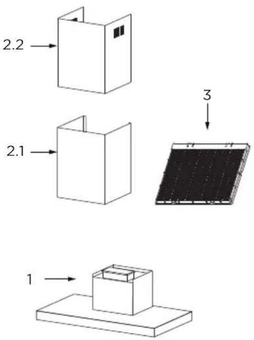
Qty. Documentation
1 Instruction Manual
| Ref. Qty. Optional Installation Components | ||
| 10 | 7 | Screws M5 x 1.97" |
| 11 | 7 | Wall Plugs |
| 12 6 Screws M4.2 x 0.37" | ||
| 20 1 | Hood fixing bracket | |
| Chimney fixing bracket 21 2 | ||
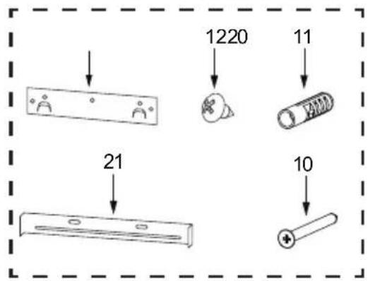
Dimensions
| Chimney | A | B | Height |
| 17.72" | 25.59"-32.28" | 17.72"-32.28"15.75"+15.35" |
Select Installation Type
A. Vented Installation
B. Non-Vented / Recirculation Installation
A. Vented Installation
- Roof Discharge
This canopy hood is designed for venting through the roof or wall.
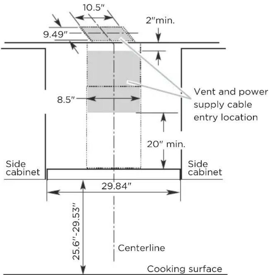
A 6" round vent system is needed for installation (not included). The hood exhaust opening is 6" round.
Vent system can terminate either through the roof or wall. To vent through a wall, a 90° elbow is needed.
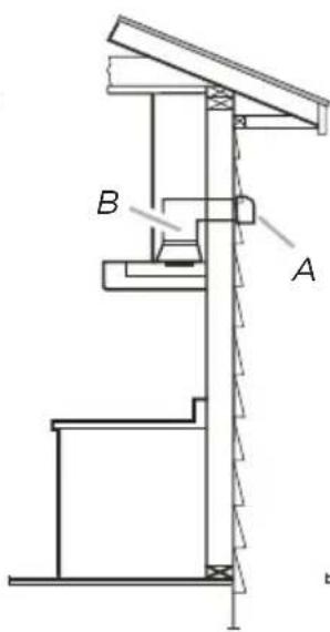
- Rear Discharge
A 90° elbow may be installed immediately above the hood.

Warning
TO REDUCE THE RISK OF FIRE, USE ONLY METAL DUCTWORK.
- If it is not possible to vent cooking fumes and vapors to the outside, the hood can be used in the non-vented (recirculating) version, fitting a charcoal filter and the deflector (not included, you can decide whether to use according to your installation environment). Fumes and vapors are recycled through the top grille.
Roof Venting
A. Roof cap
B. 6 round vent
A. Wall cap
B. 6" round vent
Non-Vented (Recirculating) Wall Venting
A. Deflector
B. 6" round vent
Local building codes may require the use of makeup air systems when using ventilation systems greater than specified CFM of air movement. The specified CFM varies from locale to locale. Consult your HVAC professional for specific requirements in your area.
Vents and electrical should be installed in the gray shaded areas to provide a clean finished look

Caution
- Vent system must terminate to the outdoors except for non-vented (recirculating) installations.
- Do not terminate the vent system in an attic or other enclosed area.
- Do not use 4" laundry-type wall cap (plastic). Only use a metal exterior exhaust vent.
- Use metal vent only. Rigid metal vent is recommended for best performane.
- All vent joints should be taped and sealed with 2"metal foil tape.
- The length of vent system and number of elbows should be kept to a minimum to provide efficient performance.
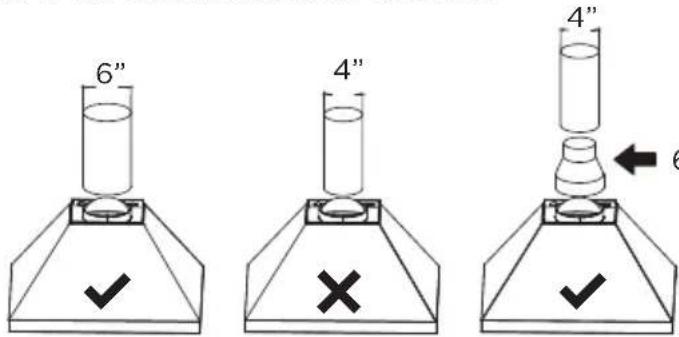
Use the correct size exhaust vent, or the range hood will not work normally!
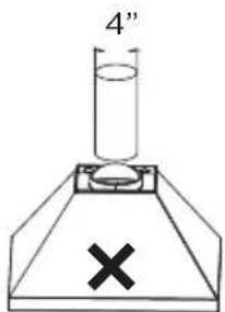
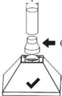
6" to 4" metal adapter
If you want to keep the wrong size exhaust vent, please install an adapter!
For the Most Efficient and Quiet Operation:
- Use no more than three 90^ elbows.
- Make sure there is a minimum of 24" of straight vent between the elbows if more than 1 elbow is used.
- Do not install 2 elbows together.
- Use clamps to seal all joints in the vent system.
• Use caulking to seal exterior wall or roof opening around the cap.
• The size of the vent should be uniform.
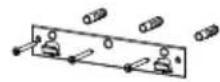
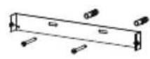
Hood Mounting Screw Installation:
1 Determine and mark the centerline on the wall where the hood will be installed.
2 Select a mounting height between a minimum of 25.6" and a suggested maximum of 29.53" above the range to the bottom of the hood. Mark a reference line on the wall.
3 Tape template in place, aligning the template centerline and bottom of template with hood bottom line and with the centerline marked on the wall.
NOTE: Ensure that horizontal lines are level prior to marking hole locations.
PRODUCT INSTALLATION
Wall Drilling And Bracket Fixing
unit: inch
| Chimney | X |
| 15.75"+15.35" | 6.3"-19.69" |
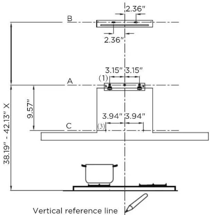
As a first step, proceed with the following drawings:
- A vertical line up to the ceiling or up to the upper limit, at the center of the area in which the hood is to be fitted.
- A horizontal line A at 38.19" - 42.13" above the cooker top.
• A horizontal line B at a X above the horizontal line A. - A horizontal line C at a 9.57" below the horizontal line A.
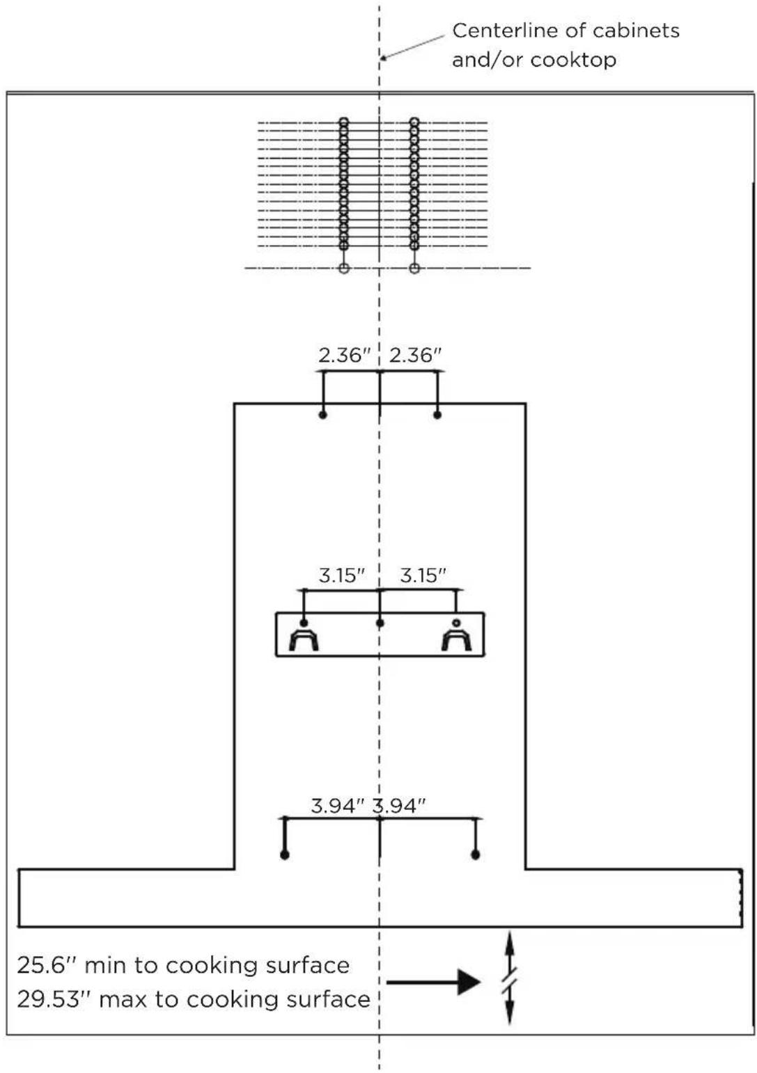
Mark Points:
- Mark a point (1) on the horizontal line A, 3.15" to the vertical reference line.
- Repeat this operation on the other side and on the vertical reference line, checking that the three marks are leveled.
- Mark a point (2) on the horizontal line B, 2.36" to the vertical reference line.
- Repeat this operation on the other side, checking that the two marks are on the same
- horizontal line.
- Mark a point (3) on the horizontal line C, 3.94" to the vertical reference line. Repeat this operation on the other side, checking that the two marks are leveled.
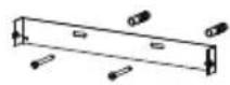
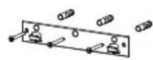
Fix the brackets :
- Drill holes at the marked points with a 10 mm drill bit.
- Insert the Wall Plugs 11 into the holes.
- Fix the hood fixing bracket 20 with 3 screws 10 (5 x 50) at the horizontal line A.
- Fix a Chimney fixing bracket 21 with 2 screws 10 (5 x 50) at the horizontal line B.
Lower decorative chimney :
- Fix the exhaust pipe on the hood body, connect chimney and hood body with 2 screws 12. connect chimney fixing bracket and chimney with 2 screws 12.
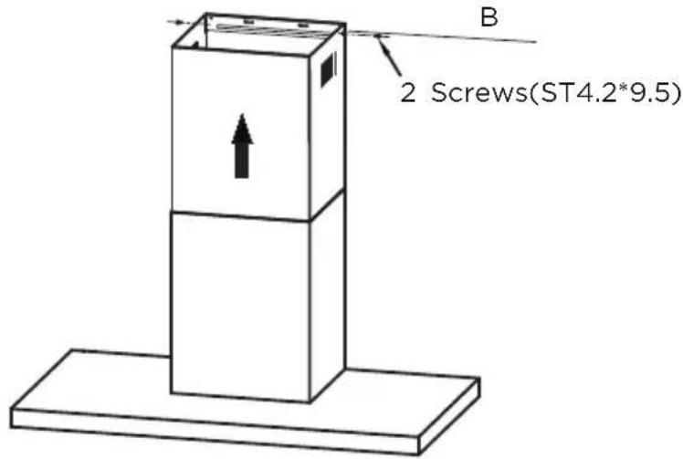
Hang and Mount the Vent Hood:
- Hang the vent hood onto fixing bracket 20.
- Level the hood, and insert 2 long screws (10) into bracket 21 at level B.
- Insert 2 long screws (10) into the hood at level A.
IMPORTANT
- The vent hood should be lifted and installed by 2 people to prevent injuries and potential damage.
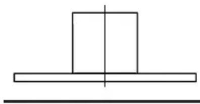
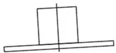
natural_image
Simple geometric diagram with a rectangle and horizontal line intersecting at the center (no text or symbols)Right
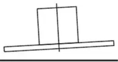
natural_image
Simple line drawing of a rectangular block resting on a horizontal line with a vertical line crossing through it (no text or symbols)Wrong
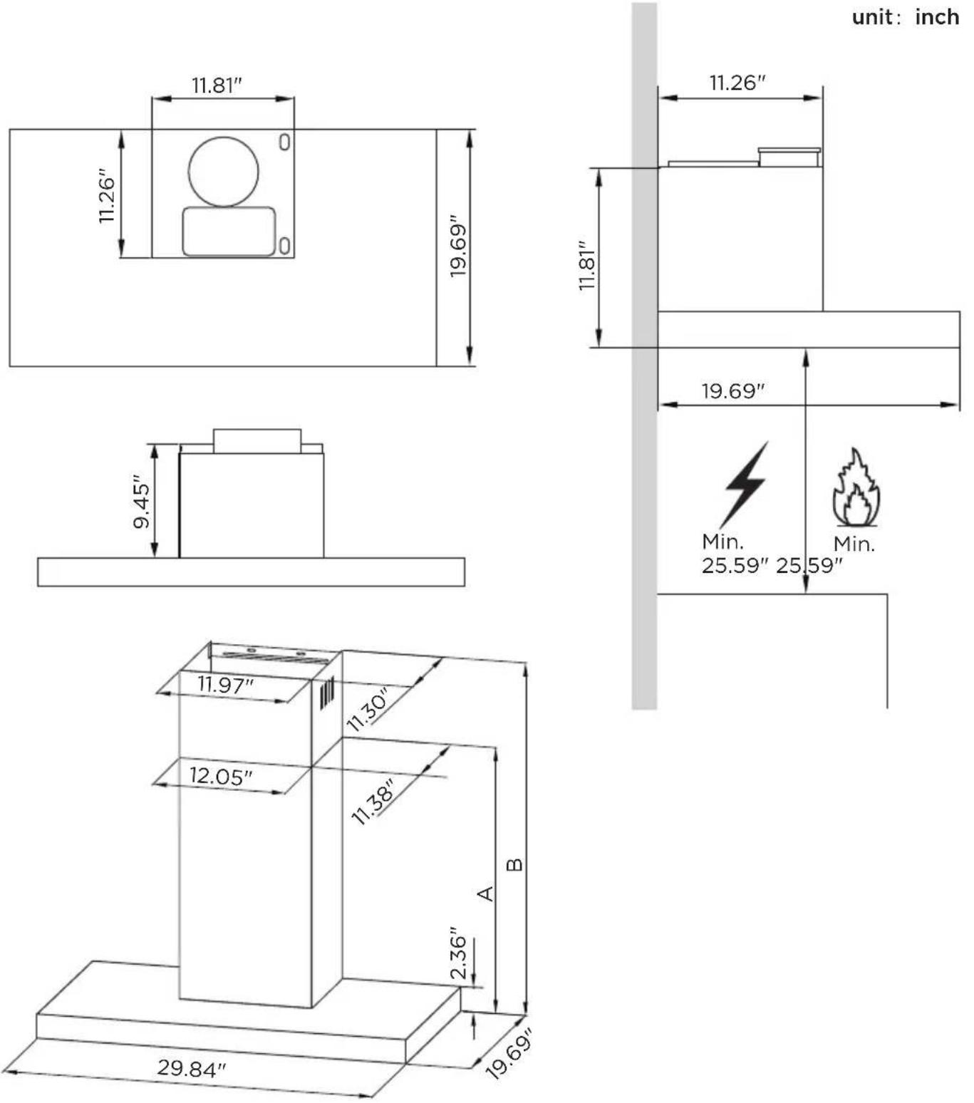
Upper Decorative Chimney:
- Insert the upper decorative chimney 2.2 into the lower decorative chimney 2.1 and drag it up to the horizontal line B.
- Connect upper decorative chimney 2.2 and chimney fixing bracket 21 with 2 screws 12.

Warning
Electrical Shock Hazard
- This unit must be grounded. This appliance is equipped with a cord having a grounding wire with a grounding plug. The plug must be plugged into an outlet that is properly installed and grounded.
- Do not use an extension cord. If the power supply cord is too short, have a qualified electrician install an outlet near the appliance.
B. Non-Vented / Recirculation Installation
Recirculation Mode:
• Install Carbon Filters.
• Install deflector according to your installation environment.
OPERATION INSTRUCTIONS
Speed Adjustment. See Below Fig(For Some Models)
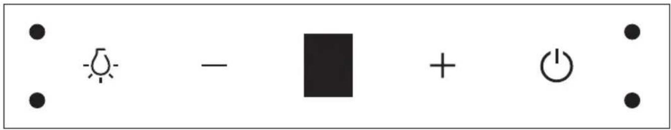
| Button Function Remarks | |||
 | Turns the lighting system on or off. | Button on. | |
| — | Reduce the fan speed. | When ⏻ + — are on. | |
 | Display fan gear "1、2、3". | When the fan is running. | |
| Display "O". | Delayed shutdown mode,or standby mode. | ||
 | Increase the fan speed. | When ⏻ + + are on. | |
| Turn the hood ON. | When ⏻ is off. | ||
| Automatic shutdown after 3 minutes. | When ⏻ is on. | ||
| Turn the hood OFF. | When ⏻ is flashing. | ||
 | Turn the machine and Lights ON. | When ⏻ is off. | Heightbetween palmand switchboard 10-15cm |
| Change the motor speedcircularly(1-2-3-1-2-3). | When ⏻ is on. | ||
 | Enter delayed shutdown mode(Automatic shutdown after 3 minutes) | When ⏻ is on. | |
| Turn the machine and Lights OFF | When ⏻ is flash. | ||
CLEANING AND MAINTENANCE
Grease Filters
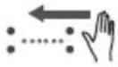
CLEANING METAL SELF-SUPPORTING GREASE FILTERS
- The filters must be cleaned frequently and can be washed in a dishwasher or a hot detergent solution.
- Depress the latch to remove the filters.
- Avoid bending the filters when washing, and allow the filters to completely dry before reinstalling (The color of the filter surface may change throughout the time but this has no influence to the filter efficiency).
- When reinstalling the filter ensure the release latches are facing down, and are securely in place.
natural_image
Illustration of a hand holding a tablet device with a finger pointing at it, showing a download arrow (no text or symbols present)
WARNING
- Do not operate your cooktop when the filters are not installed into the vent hood.
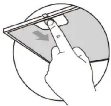
Activated Charcoal Filter (Recirculation Version)
• These filters are not washable and cannot be regenerated, and must be replaced approximately every 4 months of operation, or more frequently with heavy usage.
Replacing The Activated Charcoal Filter
- Remove the metal grease filters.
- Remove the saturated activated charcoal filter.
- Fit the new filters.
- Replace the metal grease filters.
• The service part number: 12173000A00481. - The specific installation steps for the carbon filter are provided in the instruction video on the Amazon website for this product.
Please follow the instructions carefully to ensure proper installation and operation of the filter.
natural_image
Diagram showing two solar panels inserted into a device with an arrow indicating the process (no text or symbols present)Lighting
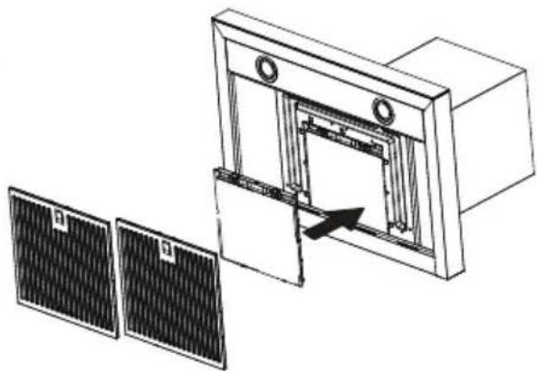
LIGHT REPLACEMENT
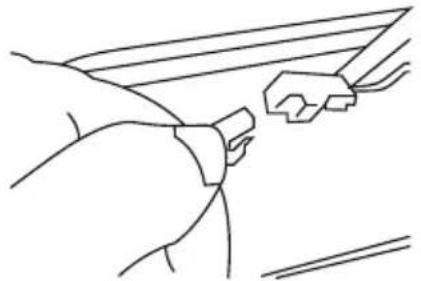
Replacing the light modules
- The entire light module must be replaced.
- Before changing the light module(s), unplug the appliance or switch off the circuit breaker in the fuse box.
- Remove the grease filter.
- Disconnect the terminal of LED light.
- Press LED light on the back of the front plate, take the LED light out.
- Replace the lamp.
natural_image
Line drawing of a hand gripping a small object, possibly a tool or device (no text or symbols present)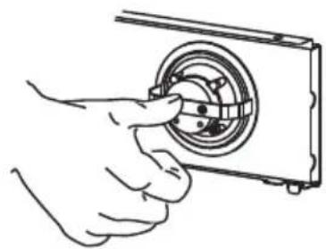
natural_image
Line drawing of a hand inserting a camera lens into a rectangular frame (no text or symbols)| Max Power Voltage Picture Service Number | ||||
| Round/Diameter: 2.76" | 1.5W DC 12V | 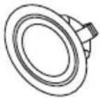 | 17473000000136 | |
Reinstalling the LED Light Module
- Press LED light on the front of front plate, install the LED light on the front plate.
- Connect the terminal of LED light and light leads.
- Reinstall the grease filter.
TROUBLESHOOTING
| Possible reason SolutionProblem | ||
| Light on, but motor does not work | The blades are blocked. | Check the blades |
| The capacitor is damaged. | Replace capacitor. | |
| The motor is damaged. | Replace motor. | |
| The internal wiring of motor is cut off/disconnected. An unpleasant smell may be produced. | Replace motor. | |
| Both light andmotor do notwork | Apart from the above mentioned, check the following: | |
| Light damaged. Replace lights. | ||
| Power cord loose. Connect the wires as the electric diagram. | ||
| Oil leakage | Outlet and the air ventilation entrance are not tightly sealed. | Take down the outlet and seal with glue. |
| Vibration | The blade, if damaged, can cause vibrating. | Replace the blade. |
| The motor is not tightly fastened. | Fasten the motor tightly. | |
| The cooker hood is not tightly fixed. | Fixed the cooker hood tightly. | |
| Insufficient suction | The distance between the cooker hood and the cooker top is too large. | Readjust the distance. |
| Too much ventilation from open doors or windows. | Choose a new place to install the appliance or close some doors / windows. | |
| The machine inclines | The fixing screws are not tight enough. | Tighten the fixing screw and make it horizontal. |
| The hanging screws are not tightenough | Tighten the hanging screw and make it horizontal. | |
TRADEMARKS, COPYRIGHTS AND LEGAL STATEMENT
Midea logo, word marks, trade name, trade dress and all versions thereof are valuable assets of Midea Group and/or its affiliates (“Midea”), to which Midea owns trademarks, copyrights and other intellectual property rights, and all goodwill derived from using any part of an Midea trademark. Use of Midea trademark for commercial purposes without the prior written consent of Midea may constitute trademark infringement or unfair competition in violation of relevant laws.
This manual is created by Midea and Midea reserves all copyrights thereof. No entity or individual may use, duplicate, modify, distribute in whole or in part this manual, or bundle or sell with other products without the prior written consent of Midea.
All the described functions and instructions were up to date at the time of printing this manual. However, the actual product may vary due to improved functions and designs.
DISPOSAL AND RECYCLING
Important instructions for environment
Compliance with the WEEE Directive and Disposing of the Waster Product: This product complies with EU WEEE Directive (2012/19/EU). This product bears a classification symbol for waster electrical and electronic equipment (WEEE).
This symbol indicates that this product shall not be disposed with other household wastes at the end of its service life. Used device must be returned to official collection point for recycling of electrical electronic devices. To find these collection systems please contact to your local authorities or retailer where the product was purchased. Each household performs important role in recovering and recycling of old appliance. Appropriate disposal of used appliance helps prevent potential negative consequences for the environment and human health.
natural_image
Symbol of a trash bin crossed with a diagonal line and a horizontal bar below (no text or numbers present)Compliance with RoHS Directive
The product you have purchased complies with EU RoHS Directive (2011/65/EU). It does not contain harmful and prohibited materials specified in the Directive.
Package information
Packaging materials of the product are manufactured from recyclable materials in accordance with our National Environment Regulations. Do not dispose of the packaging materials together with the domestic or other wastes. Take them to the packaging material collection points designated by the local authorities.

natural_image
Recycling symbol with four chasing arrows forming a triangle (no text or labels)DATA PROTECTION NOTICE
For the provision of the services agreed with the customer, we agree to comply without restriction with all stipulations of applicable data protection law, in line with agreed countries within which services to the customer will be delivered, as well as, where applicable, the EU General Data Protection Regulation (GDPR).
Generally, our data processing is to fulfil our obligation under contract with you and for product safety reasons, to safeguard your rights in connection with warranty and product registration questions. In some cases, but only if appropriate data protection is ensured, personal data might be transferred to recipients located outside of the European Economic Area.
Further information are provided on request. You can contact our Data Protection Officer via MideaDPO@midea.com. To exercise your rights such as right to object your personal date being processed for direct marketing purposes, please contact us via MideaDPO@midea.com. To find further information, please follow the QR Code.

make yourself at home

natural_image
Simple geometric diagram with a vertical rectangle and horizontal base, no text or symbols presentVUE D'ENSEMBLE DU PRODUIT 06
INSTALLATION DU PRODUIT 11
INSTRUCTIONS CONCERNANT LES OPERATIONS 14
NETTOYAGE ET ENTRETIEN 15
RÉSOLUTION DES PROBLÈMES 17
MARQUES, DROITS D'AUTEUR ET DÉCLARATION LÉGALE 18
ÉLIMINATION ET RECYCLAGE 19
AVIS DE PROTECTION DES DONNÉES 20
INSTRUCTIONS DE SÉCURITÉ
Utilisation prévue
VUE D'ENSEMBLE DU PRODUIT
Éléments
A. Chapeau de toit
A. Capuchon mural
A. Déflecteur
B. Évent rond de 6"
B. Évent rond de 6"
B. Évent rond de 6"
Use the correct size exhaust vent, or the range hood will not work normally!
6" to 4" metal adapter
If you want to keep the wrong size exhaust vent, please install an adapter!
INSTALLATION DU PRODUIT
natural_image
Simple geometric diagram with a rectangle and a horizontal line intersecting at the center (no text or symbols)Droite
natural_image
Simple line drawing of a rectangular block resting on a horizontal line with a vertical centerline (no text or symbols)Incorrecte
natural_image
Illustration of a hand interacting with a tablet device, showing a finger pointing at the screen (no text or symbols present)
AVERTISSEMENT
natural_image
Diagram showing two solar panels inserted into a device with an arrow indicating direction (no text or symbols present)Éclairage
REEMPLACEMENT DE LA LUMIÈRE
natural_image
Line drawing of a hand gripping a small object, possibly a tool or device (no text or symbols present)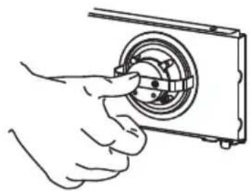
natural_image
Line drawing of a hand inserting a camera lens into a rectangular frame (no text or symbols)natural_image
Symbol of a trash bin crossed with a diagonal line and a horizontal line, representing waste sorting or disposal (no text present)natural_image
Recycling symbol with three chasing arrows forming a triangle (no text or labels)AVIS DE PROTECTION DES DONNÉES
make yourself at home

www.midea.com

- USER MANUAL
- THANK YOU LETTER
- CONTENTS
- SAFETY INSTRUCTIONS
- Intended Use
- WARNING
- TO REDUCE THE RISK OF FIRE, ELECTRIC SHOCK OR INJURY TO PERSONS, OBSERVE THE FOLLOWING:
- TO REDUCE THE RISK OF A RANGE TOP GREASE FIRE:
- TO REDUCE THE RISK OF INJURY TO PERSONS IN THE EVENT OF A RANGE TOP GREASE FIRE, OBSERVE THE FOLLOWING\*:
- CAUTION
- SAVE THESE INSTURCTIONS
- PRODUCT OVERVIEW
- Dimensions
- Select Installation Type
- Vented Installation
- TO REDUCE THE RISK OF FIRE, USE ONLY METAL DUCTWORK.
- For the Most Efficient and Quiet Operation:
- Hood Mounting Screw Installation:
- PRODUCT INSTALLATION
- Wall Drilling And Bracket Fixing
- As a first step, proceed with the following drawings:
- Mark Points:
- Fix the brackets :
- Lower decorative chimney :
- Hang and Mount the Vent Hood:
- IMPORTANT
- Upper Decorative Chimney:
- Electrical Shock Hazard
- Non-Vented / Recirculation Installation
- OPERATION INSTRUCTIONS
- CLEANING AND MAINTENANCE
- Grease Filters
- CLEANING METAL SELF-SUPPORTING GREASE FILTERS
- Activated Charcoal Filter (Recirculation Version)
- Replacing The Activated Charcoal Filter
- Lighting
- LIGHT REPLACEMENT
- Replacing the light modules
- Reinstalling the LED Light Module
- TROUBLESHOOTING
- TRADEMARKS, COPYRIGHTS AND LEGAL STATEMENT
- DISPOSAL AND RECYCLING
- Important instructions for environment
- Compliance with RoHS Directive
- Package information
- DATA PROTECTION NOTICE
- INSTRUCTIONS DE SÉCURITÉ
- Utilisation prévue
- VUE D'ENSEMBLE DU PRODUIT
- INSTALLATION DU PRODUIT
- AVERTISSEMENT
- Éclairage
- REEMPLACEMENT DE LA LUMIÈRE
- AVIS DE PROTECTION DES DONNÉES
Brand : MIDEA
Model : MVT30W9AST
Category : Basket