YWED6720RU - Dryer WHIRLPOOL - Free user manual and instructions
Find the device manual for free YWED6720RU WHIRLPOOL in PDF.

| Product type | Electric vented dryer |
| Brand | Whirlpool |
| Model | YWED6720RU |
| Dimensions (W x D x H) | 27 in x 27 in x 39 in (approx.) |
| Weight | 200 lb (90.7 kg) |
| Power supply | 120/240 V, 30 A, 60 Hz, single phase |
| Exhaust type | Rigid or flexible metal conduit 4 in (102 mm) |
| Capacity | 7.0 cu ft (approx.) |
| Controls | Electronic with display |
| Drying programs | Automatic with moisture sensing, preset programs |
| Options | Air only, child lock (not specified, omit) |
| Lint filter cleaning | Before each load |
| Drum cleaning | Damp cloth, mild detergent |
| Exhaust duct maintenance | Every 2 years by a professional |
| Safety | Moisture sensor, end-of-cycle stop, overheat protection |
| Adjustable feet | Yes, 4 leveling feet |
| Door reversal | Possible (see instructions) |
| Mobile home installation | Yes, with metal exhaust kit |
| Spare parts | Available from manufacturer |
| Warranty | Consult quick start guide |
Frequently Asked Questions - YWED6720RU WHIRLPOOL
User questions about YWED6720RU WHIRLPOOL
0 question about this device. Answer the ones you know or ask your own.
Ask a new question about this device
Download the instructions for your Dryer in PDF format for free! Find your manual YWED6720RU - WHIRLPOOL and take your electronic device back in hand. On this page are published all the documents necessary for the use of your device. YWED6720RU by WHIRLPOOL.
USER MANUAL YWED6720RU WHIRLPOOL
ELECTRIC DRYER OWNER'S MANUAL
GUIDE D'UTILISATION DE LA SÉCHEUSE ÉLECTR
Table of Contents/Table des matières
DRYER SAFETY 2 SÉCURITÉ DE LA SÉCHEUSE 21
Your safety and the safety of others are very important.
We have provided many important safety messages in this manual and on your appliance. Always read and obey all safety messages.

This is the safety alert symbol.
This symbol alerts you to potential hazards that can kill or hurt you and others.
All safety messages will follow the safety alert symbol and either the word "DANGER" or "WARNING." These words mean:
DANGER
WARNING
You can be killed or seriously injured if you don't immediately follow instructions.
You can be killed or seriously injured if you don't follow instructions.
All safety messages will tell you what the potential hazard is, tell you how to reduce the chance of injury, and tell you what can happen if the instructions are not followed.

WARNING — “Risk of Fire”
- Clothes dryer installation must be performed by a qualified installer.
- Install the clothes dryer according to the manufacturer's instructions and local codes.
- Do not install a clothes dryer with flexible plastic venting materials or flexible metal (foil type) duct. If flexible metal duct is installed, it must be of a specific type identified by the appliance manufacturer as suitable for use with clothes dryers. Flexible venting materials are known to collapse, be easily crushed, and trap lint. These conditions will obstruct clothes dryer airflow and increase the risk of fire.
- To reduce the risk of severe injury or death, follow all installation instructions.
- Save these instructions.
IMPORTANT SAFETY INSTRUCTIONS
WARNING: To reduce the risk of fire, electric shock, or injury to persons when using your appliance, follow basic precautions, including the following:
- Read all instructions before using the appliance.
- Do not use heat to dry articles containing foam rubber or in similarly textured rubber-like materials.
■ Do not dry articles that have been previously cleaned washed in, soaked in, or spotted with gasoline, dry-clean solvents, or other flammable or explosive substances, as they give off vapors that could ignite or explode.
Ring Clean lint screen before or after each load. - Keep area around the exhaust opening and adjacent surrounding areas free from the accumulation of lint, dust, t and dirt.
■ Risk of Suffocation and Injury from Entrapment: Do not allow children to play on or in the appliance. Close supervision of children is necessary when the appliance used near children.
■ The interior of the appliance and exhaust duct should be is cleaned periodically by qualified service personnel.
■ Before the appliance is removed from service or disca remove the door to the drying compartment.
■ Do not place items exposed to cooking oils in your dryer. Items contaminated with cooking oils may contribute to a chemical reaction that could cause a load to catch fire. To g. reduce the risk of fire due to contaminated loads, the final part of a tumble dryer cycle occurs without heat (cool down period). Avoid stopping a tumble dryer before the end of the drying cycle unless all items are quickly removed and spread out so that the heat is dissipated.
■ Do not reach into the appliance if the drum is moving.
Do not use replacement parts that have not been recommended by the manufacturer (e.g. parts made at home using a 3D printer).
■ Do not install or store this appliance where it will be exposed to the weather.
■ See the Installation Instructions for grounding requirements and installation.
■ Do not tamper with controls.
■ Donot install a booster fan in the exhaust duct.
■ Do not repair or replace any part of the appliance of any servicing unless specifically recommended in the use maintenance instructions or in published user-repair instructions that you understand and have the skills to out.
NOTE: The booster fan warning does not apply to clothes dryers intended to be installed in a multiple clothes dryer system, with an engineered exhaust duct system that is installed per the clothes dryer manufacturer's guidelines.
■ Do not use fabric softeners or products to eliminate unless recommended by the manufacturer of the fabric softener or product.
SAVE THESE INSTRUCTIONS
IMPORTANT SAFETY INSTRUCTIONS
WHEN DISCARDING OR STORING YOUR OLD CLOTHES DRYER, REMOVE THE DOOR.
SAVE THESE INSTRUCTIONS
Internet Connectivity Guide for Connected Appliances Only
IMPORTANT: Proper installation of your appliance prior to use is your responsibility. Be sure to read and follow the installation instructions that came with your appliance.
Connectivity requires Wi-Fi and account creation. App features and functionality are subject to change. Data rates may apply. Once installed, launch the app. You will be guided through the steps to set up a user account and to connect your appliance.
You Will Need:
A home wireless router supporting Wi-Fi, 2.4 Ghz with WPA2 security. If you are unsure of your router's capabilities, refer to the router manufacturer's instructions.
■ The router to be on and have a live internet connection.
■ The 10-character SAID code for your appliance. The SAID code is either printed on a label on the appliance or found on the LCD screen.
Federal Communications Commission (FCC) Compliance Notice
This device complies with Part 15 of the FCC Rules. Operation is subject to the following two conditions:
-
This device may not cause harmful interference, and
-
This device must accept any interference received, including interference that may cause undesired operation.
Changes or modifications not expressly approved by the party responsible for compliance could void the user's authority to operate the equipment.
Industry Canada (IC) Compliance Notice
This Device complies with Industry Canada License-exempt RSS standard(s). Operation is subject to the following two conditions:
-
This device may not cause interference.
-
This device must accept any interference, including interference that may cause undesired operation of the device.
Under Industry Canada regulations, this radio transmitter may only operate using an antenna of a type and maximum (or lesser) gain approved for the transmitter by Industry Canada. To reduce potential radio interference to other users, the antenna type and its gain should be so chosen that the equivalent isotropically radiated power (e.i.r.p.) is not more than that necessary for successful communication.
To comply with FCC and Industry Canada RF radiation exposure limits for general population, antenna(s) used for this transmitter must be installed such that a minimum separation distance of 20 cm is maintained between the radiator (antenna) and all persons at all times and must not be co-located or operating in conjunction with any other antenna or transmitter.
If this equipment does cause hainterference to radio or television reception, which can be determined by turning the equipment off and on, the user is encouraged to try to correct the interference by one of the following measures:
■ Reorient or relocate the receiving antenna.
■ Increase the separation between the equipment and
■ Connect the equipment into an outlet on a circuit different from that to which the receiver is connected.
■ Consult the dealer or an experienced radio/TV technician for help.
DRYER MAINTENANCE AND CARE
Cleaning the Dryer Location
WARNING
Explosion Hazard
Keep flammable materials and vapors, such as gasoline, away from dryer.
Do not dry anything that has ever had anything flammable on it (even after washing).
Place dryer at least 18 inches (460 mm) above the for a garage installation.
Failure to do so can result in death, explosion, or
Keep dryer area clear and free from items that would airflow for proper dryer operation. This includes clearing laundry in front of the dryer.
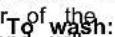
Cleaning the Dryer Interior
To clean dryer drum:
- Use nonflammable cleaner or a mild hand dish detergent mixed at a low concentration with very warm water, with a soft cloth.
■ Rinse well with a wet sponge or towel.
■ Tumble a load of clean clothes or towels to dry drum.
OR
- Use a microfiber cloth and very warm water in a spray clean the drum and a second microfiber towel to dry.
NOTE: Garments that contain unstable dyes, such as denim residue buildup.
jeans or brightly colored cotton items, may discolor the rear of the.
dryer interior. These stains are not harmful to your dryer and will not stain future loads of clothes. Dry unstable dye items inside Roll tint off the screen with your fingers.
to avoid transfer of dye.
Removing Accumulated Lint
From inside the dryer cabinet:
Lint should be removed every 2 years, or more often, depending on dryer usage. Cleaning should be done by a qualified appliance service or ventilation system cleaner.
From the exhaust vent:
Lint should be removed every 2 years, or more often, depending on dryer usage.
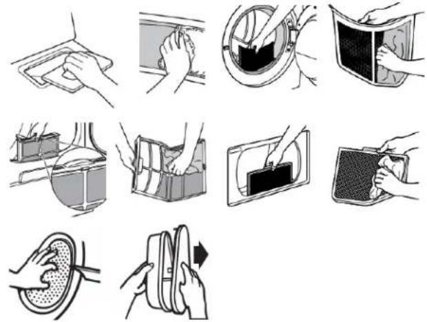
Cleaning the Lint Screen
Every load cleaning:
The lint screen may be located either in the door opening top of the dryer depending on model. A screen blocked by increase drying time.
To clean:
- Remove the lint screen. If necessary, press the tab to relea and open the lint screen. Roll lint off the screen with your fingers. Do not rinse or wash screen to remove lint. Wet I hard to remove.
floor
- Push the lint screen firmly back into place.
IMPORTANT:
block the piles Do not run the dryer with the lint screen loose, damaged, blocked, or missing. Doing so can cause overheating and damage to both the dryer and fabrics.
If lint falls off the screen into the dryer during removal, chthe exhaust hood and remove the lint. See "Venting Requirements" in the Installation Instructions.
■ Clean space where lint screen is located, as needed. Using vacuum, gently remove any lint that has accumulated outside of the lint screen.
As-needed cleaning:
Laundry detergent and fabric softener residue can build up on lint screen. This buildup can cause longer drying times for your clothes, or cause the dryer to stop before your load is completely dry. The screen is probably clogged if lint falls off while the s is in the dryer. Clean the lint screen with a nylon brush every 6 months, or more frequently, if it becomes clogged due to a
1 side Roll out lint off the screen with your fingers.
- Wet both sides of lint screen with hot water.
- Wet a nylon brush with hot water and liquid detergent. Scrul lint screen with the brush to remove residue buildup.

- Rinse screen with hot water.
- Thoroughly dry lint screen with a clean towel. Reinstall scree in dryer.
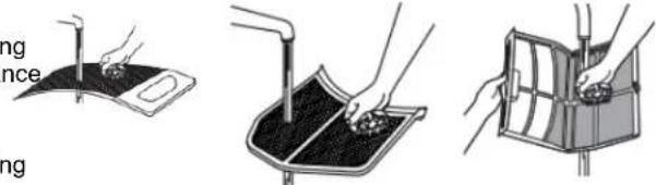
Changing the Drum Light (on some models)
Use no more than four 90° elbows in a vent system; each bend and curve reduces airflow.
-
Unplug dryer or disconnect power.
-
Open the dryer door. Locate the light bulb cover on the back wall of the dryer. Using a 1/4" (6.5 mm) nut driver or socket wrench, remove the screw located in the lower right-hand corner of the cover. Remove the cover.
natural_image
Hand holding a wrench to switch a device from a wall-mounted screen (no text or symbols visible)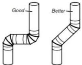
- Turn bulb counterclockwise. Replace the bulb with a 10 appliance bulb only. Replace the cover and secure with screw.
- Plug in dryer or reconnect power.
Check Your Vent System for Good Airflow
WARNING

Fire Hazard
Use a heavy metal vent.
Do not use a plastic vent.
Do not use a metal foil vent.
Failure to follow these instructions can result in death fire.
Good Airflow
Along with heat, dryers require good airflow to efficiently dry laundry. Proper venting will reduce your drying times and in your energy savings. See Installation Instructions.
The venting system attached to the dryer plays a big role airflow. Blocked or crushed vents as well as improper venting installation will reduce air flow and dryer performance.
Service calls caused by improper venting are not covered by warranty and will be paid by the customer, regardless of w installed the dryer. To clean or repair venting, contact a ve specialist.
Maintain Good Airflow
■ Cleaning your lint screen before each load.
■ Replace plastic or foil vent material with 4" (102 mm) diameter heavy, rigid vent material.
■ Use the shortest length of vent possible.
■ Remove lint and debris from the exhaust hood.
■ Remove lint from the entire length of the vent system at 15 every 2 years. When cleaning is complete, be sure to follow the Installation Instructions for final product check.
■ Clear away items from the front of the dryer.
Nonuse, Storage, and Moving Care the Nonuse or Storage Care
If you will be on vacation or not using your dryer for an ext period of time, you should:
- Unplug dryer or disconnect power.
- Clean lint screen. See "Cleaning the Lint Screen."
- Steam Models Only: Turn off the water supply to the dryer. This helps to avoid flooding (due to a water pressure surge while you are away.
Moving Care
For power supply cord-connected dryers:
- Unplug the power supply cord.
- Steam models only: Shut off water faucet. Disconnect the water inlet hose from faucet; then drain the hose. Transport hose separately.
- Make sure leveling legs are secure in dryer base.
- Use tape to secure dryer door.
- On models with base trim, remove base trim before moving dryer. See "Install and remove base trim (on some models)" for details.
For direct-wired dryers:
WARNING
prove

in good
the
Disconnect power before servicing.
^ting Replace all parts and panels before operating.
Failure to do so can result in death or electrical shock.
- Turn off power at fuse or breaker box.
- Disconnect wiring.
- Steam models only: Shut off water faucet. Disconnect the water inlet hose from faucet; then drain the hose. Transport hose separately.
- Make sure leveling legs are secure in dryer base.
- Use tape to secure dryer door.
- On models with base trim, remove base trim before moving dryer. See "Install and remove base trim (on some models)" for details.
To winterize the dryer:
- Unplug dryer or disconnect power.
- Shut off water faucet.
- Disconnect water inlet hose from faucet and drain.
To use the dryer again:
- Flush water pipes. Reconnect water inlet hose to faucet. on water faucet.
- Plug in dryer or reconnect power as described in the Installation Instructions.
Reinstalling the Dryer
Follow the Installation Instructions to locate, level, and connect dryer.
Special Instructions for Steam Models
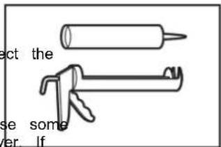
Install and store your dryer where it will not freeze. Because some water may stay in the hose, freezing can damage your dryer. If storing or moving your dryer during freezing weather, winterizing gun and compound Adjustable wrench that opens
Water inlet hose
Replace inlet hose and hose screen after 5 years of use to reduce
the risk of hose failure. Periodically inspect and replace inlet hose Additional Tools Needed (on some models):
if bulges, kinks, cuts, wear, or leaks are found.
When replacing your inlet hose, record the date of replacement.
INSTALLATION REQUIREMENTS
Tools and Parts
NOTE: Install the clothes dryer according to the manufacturer's instructions and local codes.
Gather required tools and parts before starting installation. Read and follow the instructions provided with any tools listed her Parts Supplied (all models):
Tools Needed for All Installations:
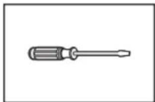
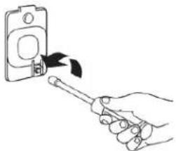
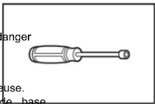
natural_image
Simple line drawing of a screwdriver (no text or symbols)Flat-blade screwdriver
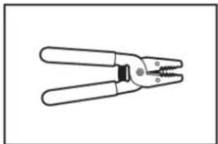
natural_image
Line drawing of a pair of wire crimping tools (no text or symbols)Wire stripper
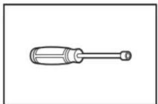
natural_image
Simple line drawing of a screwdriver with a handle and shaft (no text or symbols)1/4" Nut driver
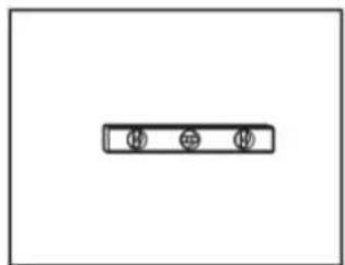
natural_image
Simple diagram with three circular symbols inside a rectangular box (no text or labels)Level
natural_image
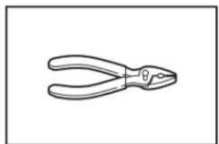
Line drawing of a pair of pliers (no text or symbols)Pliers
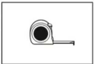
natural_image
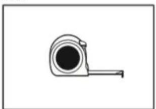
Simple line drawing of a tape measure (no text or symbols)Tape measure
natural_image
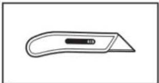
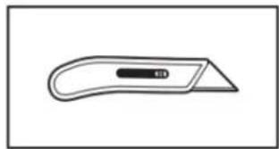
Simple line drawing of a flat tool with a handle and central slot (no text or symbols)Utility knife
natural_image
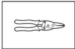
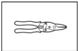
Line drawing of a pair of pliers with a handle and base, no text or symbols presentTin snips
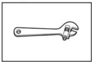
natural_image
Line drawing of an adjustable wrench (no text or symbols)Adjustable wrench that opens to 1" (25 mm) or hex-head socket wrench
to reduce Additional Tools Needed (on some models):
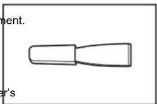
natural_image
Simple line drawing of a tool or component with no text or symbolsPutty knife
Parts Supplied (all models):
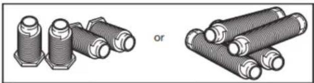
natural_image
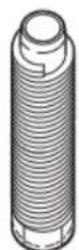
Illustration of two types of threaded fasteners with hexagonal end caps, one labeled 'or', no text or symbols present.Leveling legs (4) (Length and appearance of legs may vary according to model)
Parts package is located in dryer drum. Check that all parts are included.
NOTE: Do not use leveling legs supplied with dryer if installing with a pedestal or stack kit.
Parts Needed (steam models):
natural_image
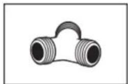
Simple line drawing of a T-shaped pipe fitting with two threaded ends (no text or symbols)"Y" connector
natural_image
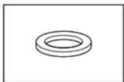
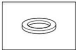
Simple line drawing of a ring-shaped object (no text or symbols)Rubber washer
natural_image
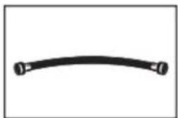
Simple black curved line with two small circular ends, no text or symbols present2' (0.6 m) inlet hose
natural_image
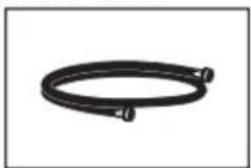
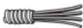
Coiled black cable or hose with two connectors (no text or symbols visible)5' (1.52 m) inlet hose
Vented Models:
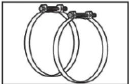
natural_image
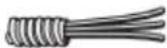
Two interlocked metal rings with black connectors (no text or symbols)Vent Clamps, elbows, and vent work
Parts Needed (not supplied with dryer):
Additional parts may be required, depending on your ins Check local codes. Check existing electrical supply and See "Electrical Requirements" and "Venting Requirements" before purchasing parts.
Mobile home installations require metal exhaust system h available for purchase from the dealer from whom you your dryer. For further information, please refer to the Guide for service contact information.
Available Accessories:
Accessories and replacement parts are available for your m For ordering and contact information, please reference your Start Guide.
Location Requirements
WARNING
Explosion Hazard
Keep flammable materials and vapors, such as gaso away from dryer.
Do not dry anything that has ever had anything flammable on it (even after washing).
Place dryer at least 18 inches (460 mm) above the for a garage installation.
Failure to do so can result in death, explosion, or fire.
Check code requirements. Some codes limit, or do not permit, installing dryer in garages, closets, mobile homes, or sleeping quarters. Contact your local building inspector.
You will need:
■ For vented models: A location allowing for proper exhaust installation. See "Venting Requirements."
■ A separate 30 A circuit for electric dryers.
If you are using power supply cord, a grounded electrical located within 2 ft (610 mm) of either side of dryer. See "Electrical Requirements."
■ A sturdy floor to support dryer weight of 200 lbs (90.7 Also, consider the combined weight of the companion appliance.
■ For steam dryers: Cold water faucets located within 4 ft (1.2 m) of the water fill valves, and water pressure of 20-120 psi (138-827 kPa). You may use the water supply for your washer using the necessary parts as noted in "Parts needed" which you may need to purchase (those parts are not included with the your appliance and are optional).
■ Level floor with a maximum slope of 1" (25 mm) under the entire dryer. If the slope is greater than 1" (25 mm), install Extended Dryer Feet Kit. If not level, clothes may not tumble properly and automatic sensor cycles may not operate correctly.
■ For garage installation, place dryer at least 18" (460 mm) above the floor. If using a pedestal, you will need 18" (460 to bottom of the dryer.
■ The dryer must not be installed or stored in an area when will be exposed to water and/or weather.
IMPORTANT: Do not operate dryer at temperatures below 45°F (17°C). Lower temperatures may cause dryer not to shut off at of automatic sensor cycles, resulting in longer drying times.
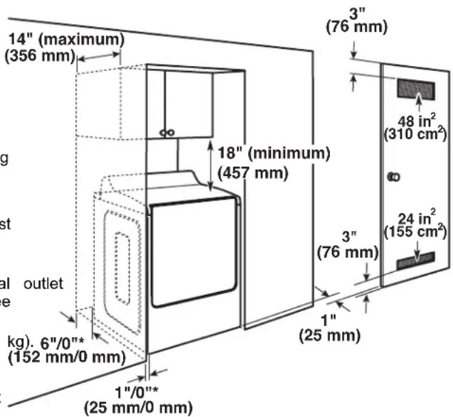
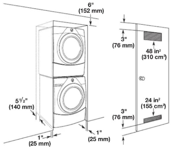
Installation clearances:
For each arrangement, consider allowing more space for ease of ware installation and servicing, spacing for companion appliances, and changes clearances for walls, doors, and floor moldings. Space must be large enough to allow the dryer door to fully open. Add spacing all sides of dryer to reduce noise transfer. If a closet door is used, top and bottom air openings are required. Louvered doors with equivalent ventilation openings can be used.
Quick Installation spacing for a recessed area or closet All dimensions show recommended and minimum spacing allowed.
■ Additional spacing should be considered for ease of installation and servicing.
■ Additional clearances might be required for wall, door, floor, moldings, dryer venting, and drain system.
■ Additional spacing should be considered on all sides of the dryer to reduce noise transfer.
■ For closet installation with a door, minimum ventilation openings in the top and bottom of the door are required fo vented models. Louvered doors with equivalent ventilation openings are acceptable.
■ Companion appliance spacing should also be considered.
Recommended installation clearances (dryer only):
Custom under-counter installation:
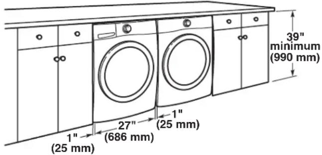
Closet Installation (stacked washer and dryer):
Minimum installation clearances (dryer only):
| Front Sides | Rear Top | |||
| Recessed | NA 0" (0 mm) | 0" (0 mm) | mm) NA | |
| Closet | 1" (25 mm) | 0" (0 mm) | 0" (0 mm) | NA |
| Under Counter | NA 1" (25 mm) | 0" (0 mm) | 0" (0 mm) |
0" (0 mm) rear spacing is allowed for straight-back venting. For steam models only, inlet hose must not be kinked.
Mobile Home – Additional installation requirements
This dryer is suitable for mobile home installations. The installation must conform to the Manufactured Home Cor and Safety Standard, Title 24 CFR, Part 3280 (formerly
Federal Standard for Mobile Home Construction and Safety, 24, HUD Part 280) or the Standard for Mobile Homes, C Z240 MH.
Mobile home installations require:
■ Metal exhaust system hardware, which is available for purchase from your dealer.
■ Special provisions must be made in mobile homes to introduce outside air into the dryer. The opening (such as a nearby window) should be at least twice as large as the dryer exhaust opening.
Electrical Requirements - U.S.A.
It is your responsibility:
■ To contact a qualified electrical installer.
To be sure that the electrical connection is adequate and in conformance with the National Electrical Code, ANSI/NFPA 70 – latest edition and all local codes and ordinances. The National Electrical Code requires a 4-wire power supply connection for homes built after 1996, dryer circuits involved remodeling after 1996, and all mobile home installations. A copy of the above code standards can be obtained from: National Fire Protection Association, One Batterymarch Park, Quincy, MA 02169–7471.
■ To supply the required 3- or 4-wire, single-phase, 120/240 V, 60 Hz AC only electrical supply (or 3- or 4-wire, 120/208 V electrical supply, if specified on the serial/rating plate) on a separate 30 A circuit, fused on both sides of the line. Connect to an individual branch circuit. Do not have a fuse in the neutral or grounding circuit.
■ Do not use an extension cord.
If codes permit and a separate ground wire is used, it is recommended that a qualified electrician determine that the ground path is adequate.
Electrical Connection
To properly install your dryer, you must determine the type of electrical connection you will be using and follow the instructions provided for it here.
This dryer is manufactured ready to install with a 3-wire electrical supply connection. The neutral bond conductor is permanently connected to the neutral conductor (white wire) within the dryer. If the local electrical codes require the use ground-fault circuit interrupter, then a 4 wire electrical supply connection is required. The neutral bond conductor must be removed from the external ground connector (green screw), and secured under the neutral terminal (center or white wire) of the terminal block. When the neutral bond conductor is secured under the neutral terminal (center or white wire) of terminal block, the dryer cabinet is isolated from the neutral conductor. The green ground wire of the 4-wire power cord must be secured to the dryer cabinet with the green ground screw.
If local codes do not permit the connection of a neutral bc wire to the neutral wire, see "Optional 3-Wire Connection."
A 4-wire power supply connection must be used when the appliance is installed in a location where grounding through the neutral conductor is prohibited. Grounding through the neutral conductor is prohibited for (1) new branch-circuit installations after 1996, (2) mobile homes, (3) recreational vehicles, and (4) areas where local codes prohibit grounding through the neutral conductors.
If using a power supply cord:
dlose a UL listed power supply cord kit marked for use with cl dryers. The kit should contain:
Title: UL listed 30 A power supply cord, rated 120/240 V mini N/CFA. The cord should be type SRD or SRDT and be at least 4 (1.22 m) long. The wires that connect to the dryer must err ring terminals or spade terminals with upturned ends.
A UL listed strain relief.
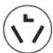
If your outlet looks like this:

4-wire receptacle (14-30R)
Then choose a 4-wire power supply cord with ring or spade terminals and UL listed strain relief. The 4-wire power supply cord, at least 4 ft (1.22 m) long, must have fo 10-gauge copper wires and match a 4-wire receptacle of NEMA Type 14-30 R. The ground wire (ground conductor) may be either green or bare. The neutral conductor must be identified by a white cover.
If your outlet looks like this:

3-wire receptacle (10-30R)
Then choose a 3-wire power supply cord with ring or spade terminals and UL listed strain relief. The 3-wire power supply cord, at least 4 ft (1.22 m) long, must have the 10-gauge copper wires and match a 3-wire receptacle of NEMA Type 10-30R.
If connecting by direct wire:
Power supply cable must match power supply (4-wire or and be:
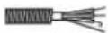
■ Flexible armored cable or nonmetallic sheathed copper cable (with ground wire), covered with flexible metallic conduit. All current-carrying wires must be insulated.
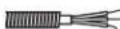
■ 10-gauge solid copper wire (do not use aluminum) at least (1.52 m) long.
GROUNDING INSTRUCTIONS
For a grounded, cord-connected appliance:
This appliance must be grounded. In the event of a malfunction or breakdown, grounding will reduce the rise electric shock by providing a path of least resistance electric current. This appliance is equipped with a core an equipment-grounding conductor and a grounding plug. The plug must be plugged into an appropriate outlet properly installed and grounded in accordance with all codes and ordinances.
WARNING: Improper connection of the equipment-grounding conductor can result in a risk of electric shock. Check with a qualified electrician or serviceman if you are doubt as to whether the appliance is properly grounded. I not modify the plug provided with the appliance: If it will the outlet, have a proper outlet installed by a qualified electrician.
For a permanently connected appliance:
This appliance must be connected to a grounded metal, permanent wiring system, or an equipment-grounding conductor must be run with the circuit conductors and connected to the equipment-grounding terminal or lead on the appliance.
SAVE THESE INSTRUCTIONS
Electric Requirements – Canada
WARNING
Electrical Shock Hazard
Plug into a grounded 4 prong outlet.
Failure to do so can result in death or electrical shock.
dt is your responsibility:
■ To contact a qualified electrical installer.
■ To be sure that the electrical connection is adequate and in conformance with Canadian Electrical Code, C22.1 – latest edition and all local codes. A copy of above codes standard may be obtained from: Canadian Standards Association, 178 Rexdale Blvd., Toronto, ON M9W 1R3 CANADA.
■ To supply the required 4-wire, single-phase, 120/240 V, 60 Hz AC-only electrical supply on a separate 30 A circuit, fused on both sides of the line. A time-delay fuse or circuit breaker is recommended. Connect to an individual branch circuit.
This, dryer is equipped with a UL-listed and/or CSA International Certified Power Cord intended to be plugged into a standard 14-30R wall receptacle. The co is 5 ft (1.52 m) long. Be sure wall receptacle is within reach of dryer's fine location.

If codes permit and a separate ground wire is used, it is recommended that a qualified electrician determine that the avinground path is adequate.
■ Do not use an extension cord.
^IS For further information, or to obtain a Power Supply Cord Replacement, please reference the contact information listed on your Quick Start Guide.
GROUNDING INSTRUCTIONS
e in
DoFor a grounded, cord-connected appliance:
This appliance must be grounded. In the event of a malfunction or breakdown, grounding will reduce the risk of electric shock by providing a path of least resistance for electric current. This appliance is equipped with a cord having an equipment-grounding conductor and a grounding plug. The plug must be plugged into an appropriate outlet that is properly installed and grounded in accordance with all local codes and ordinances.
WARNING: Improper connection of the equipment-grounding conductor can result in a risk of electric shock. Check with a qualified electrician or serviceman if you are in doubt as to whether the appliance is properly grounded. Do not modify the plug provided with the appliance: if it will not the outlet, have a proper outlet installed by a qualified electrician.
SAVE THESE INSTRUCTIONS
INSTALLATION
Install Leveling Legs
WARNING
Excessive Weight Hazard
Use two or more people to move and install or uninstall appliance.
Failure to do so can result in back or other injury.
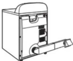
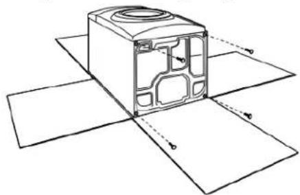
1. Prepare dryer for leveling legs
natural_image
Technical line drawing of a mechanical housing component with cross-sectional view (no text or symbols)To avoid damaging floor, use a large flat piece of cardboard from dryer carton; place under entire back edge of dryer. Firmly grasp dryer body (not console panel) and gently dryer down on cardboard.
NOTE: Residual water from factory testing may drain when dryer is laying on its side.
2. Screw in leveling legs
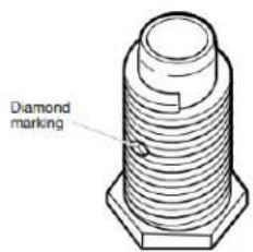
Leveling leg with diamond marking. Leveling leg without diamond marking
Using a wrench and tape measure, screw leveling legs into leg holes until bottom of foot is approximately 1/2" (13 mm) to 1 ^1/2 " (38 mm) from bottom of the dryer.
For leveling legs with the diamond marking:
Screw legs into leg holes by hand. Use a wrench to finish turning legs until diamond marking is no longer visible.
Place a carton corner post from dryer packaging under each of the two dryer back corners. Stand the dryer up. Slide the dryer on the corner posts until it is close to its final location. Leave enough room to connect the exhaust vent.
Electrical Installation - U.S.A.
WARNING

Fire Hazard
For power supply cord, use a new UL listed 30 A power supply cord.
For direct wire, use 10 gauge copper wire.
Use a UL listed strain relief.
Disconnect power before making electrical connections.
Connect neutral wire (white or center wire) to center terminal (silver).
Connect ground wire (green or bare wire) to green ground connector.
Connect remaining 2 supply wires to remaining 2 terminals (gold).
Securely tighten all electrical connections.
Failure to do so can result in death, fire, or electrical shock.
1. Disconnect power
2. Remove terminal block cover
NOTE: Your terminal block cover may be in a different location.
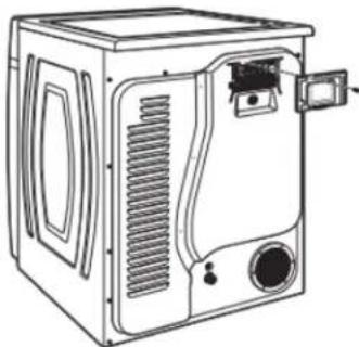
natural_image
Line drawing of a microwave oven with ventilation slots and control panel (no text or symbols)Remove hold-down screw and terminal block cover.
3. Choose electrical connection type
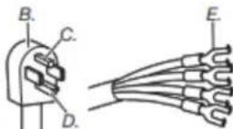
4-Wire Power Supply Connection

Power supply cord 4-wire receptacle
(NEMA Type 14-30R): Refer to "4-Wire Power Supply Connection". Then, go to "Venting Requirements."
IMPORTANT: A 4-wire connection is required for mobile homes and where local codes do not permit the use of 3-wire connections.
Power supply cord 3-wire receptacle
(NEMA Type 10-30R): Refer to "3-Wire Power Supply Connection". Then, go to "Venting Requirements."
4-wire direct connection: Go to "Direct Wire Strain Relief," then "4-Wire Direct Wire Connection," then, go to "Venting Requirements."
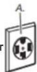
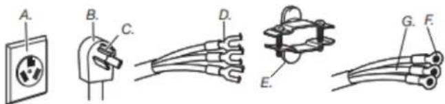
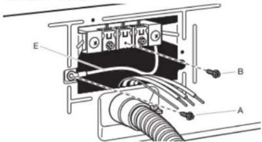
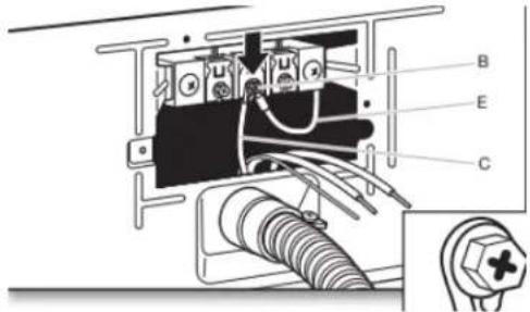
A. 4-wire receptacle (NEMA type 14-30R)
E. Spade terminals with upturned ends F. 3/4" (19 mm) UL-listed strain relief G. Ring terminals
B. 4-prong plug C. Ground prong D. Neutral prong
3-wire direct connection: Go to "Direct Strain Relief", then "3-Wire Direct Wire Connection," then, go to "Venting Requirements."
NOTE: If local codes do not permit connection of a cabinet-ground conductor to neutral wire, go to "Optional 3-wire Connection." This connection may be used with either a power supply cord or a direct wire connection.
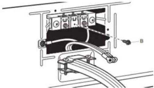
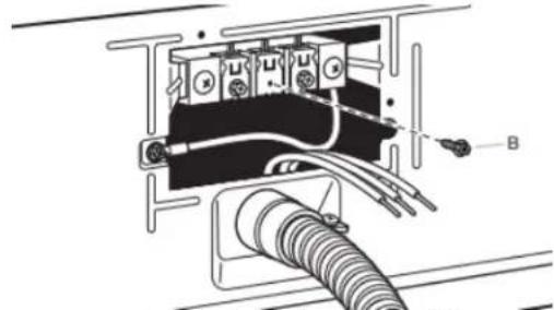
are ground wire appliance installation
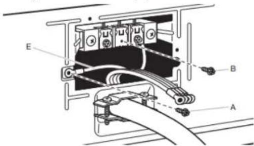
Remove center terminal block screw (B). Remove neutral bond wire (E) from green external ground conductor screw (A).
Power Supply Cord Connection
Power Supply Cord Strain Relief
1. Attach power supply cord strain relief
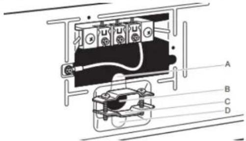
Remove the screws from a 3/4" (19 mm) UL-listed strain relief (UL marking on strain relief). Put the tabs of the two clamp sections (C) into the hole below the terminal block opening (B) so that one tab is pointing up (A) and the other is pointing down (D), and hold in place. Tighten strain relief screws just on enough to hold the two clamp sections (C) together. cent
2. Attach power supply cord to strain relief
natural_image
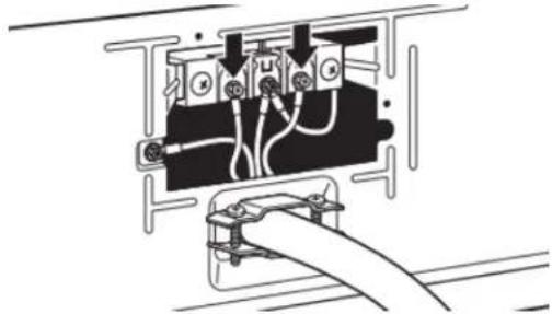
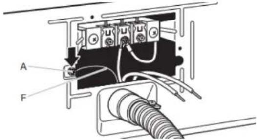
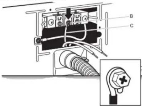
Pure electrical circuit lines without any symbols4. Connect neutral bond wire and neutral wire
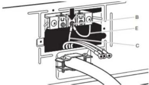
Stonnect neutral bond wire (E) and neutral wire (white or center) (C) of power supply cord under center terminal bloc screw (B). Tighten screw.
5. Connect ground wire
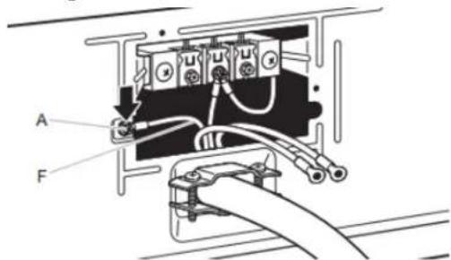
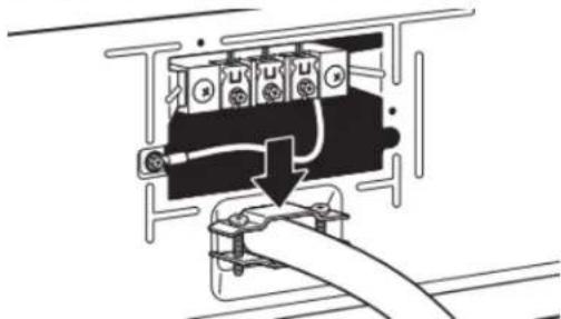
Put power supply cord through the strain relief. Be sure that the wire insulation on the power supply cord is inside the
strain relief. The strain relief should have a tight fit with the Connect ground wire (F) (green or bare) of power supply (dryer cabinet and be in a horizontal position. Tighten the stronger green external ground conductor screw (A). Tighten relief against the power supply cord. Do not overtighten the screw. strain relief screws.
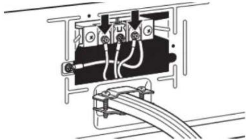
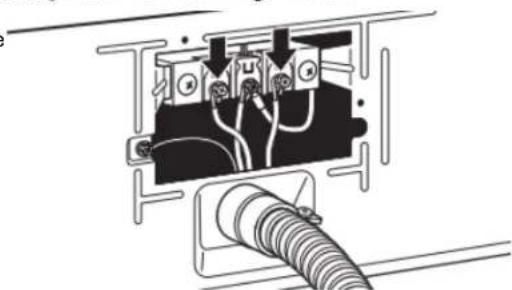
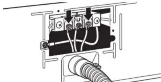
6. Connect remaining wires
natural_image
Diagram of an electrical outlet with wires and connectors, no text or symbols presentConnect remaining wires under outer terminal block screws. Tighten screws. Insert tab of terminal block cover into slot dryer rear panel. Secure cover with hold-down screw. Now, go to "Venting Requirements."
5. Connect remaining wires
natural_image
Pure electrical circuit lines without any symbolsConnect remaining wires under outer terminal block screws. Tighten screws. Insert tab of terminal block cover into slot dryer rear panel. Secure cover with hold-down screw. Now, go to "Venting Requirements."
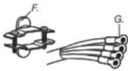
3-Wire Power Supply Connection
IMPORTANT: Use where local codes permit connecting ground conductor to neutral wire.
A. 3-wire receptacle (NEMA type 10-30R)
E. 3/4" (19 mm) UL-listed strain relief
B. 3-wire plug
F. Ring terminals
C. Neutral prong
G. Neutral (white or center wire)
D. Spade terminals with upturned ends
3. Remove center screw
natural_image
Technical diagram of an electrical connector with wires and components, no visible text or symbolsRemove center terminal block screw (B).
4. Connect neutral wire
Connect neutral wire (white or center) (C) of power supply cord under center terminal block screw (B). Tighten screw.
Direct Wire Connection
Direct wire strain relief
1. Attach direct wire strain relief
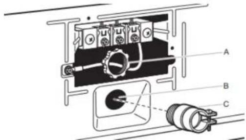
Unscrew the removable conduit connector (A) and any screws from a 3/4" (19 mm) UL-listed strain relief (UL mar on strain relief). Put the threaded section of the strain relief through the hole below the terminal block opening (B). Reaching inside the terminal block opening, screw the removable conduit connector (A) onto the strain relief thread (C) and tighten securely.
2. Attach direct wire cable to strain relief
natural_image
Pure electrical circuit lines without any symbolsPut direct wire cable through the strain relief. The strain re should have a tight fit with the dryer cabinet and be in a horizontal position. Tighten strain relief screw against the direct wire cable.
For 4-wire Direct Wire Connection, continue to step 3.
4-wire direct wire connection: Go to "4-Wire Direct Wire Connection."
For 3-wire Direct Wire Connection, continue to step 3.
3-wire direct wire connection: Go to "3-Wire Direct Wire Connection."
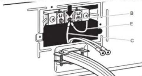
4-Wire Direct Wire Connection
IMPORTANT: A 4-wire connection is required for mobile homes and where local codes do not permit 3-wire connections.
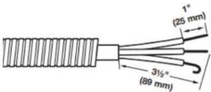
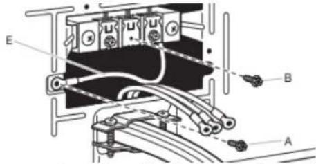
3. Prepare your 4-wire cable for direct connection
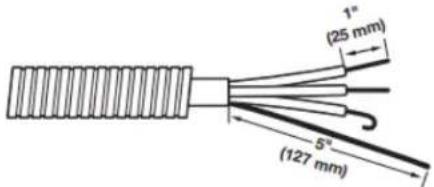
Direct wire cable must have 5 ft (1.52 m) of extra length dryer may be moved if needed.
Strip 5" (127 mm) of outer covering from end of cable, 7. le bare ground wire at 5" (127 mm) _2 " C(38 mm) from remaining 3 wires. Strip insulation back 1" (25 mm). Shape ends of wires into hooks.
4. Prepare to connect neutral bond wire and neutral wire
Remove center terminal block screw (B). Remove neutral bond wire (E) from green external bond conductor
5. Connect neutral bond wire and neutral wire
6. Connect ground wire
Connect ground wire (green or bare) (F) of direct wire cab under green external ground conductor screw (A). Tighten screw.
Connect remaining wires
natural_image
Pure electrical circuit lines without any symbolsPlace hooked ends of remaining direct wire cable wires und outer terminal block screws (hooks facing right). Squeeze hooked ends together and tighten screws. Insert tab of terminal block cover into slot of dryer rear panel. Secure cover with hold-down screw. Now, go to "Venting Requirements."
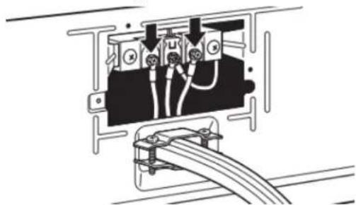
3-Wire Direct Wire Connection
IMPORTANT: Use where local codes permit connecting cabinet-ground conductor to neutral wire.
3. Prepare your 3-wire cable for direct connection
Connect neutral bond wire (E) and place hooked end (hook) Direct wire cable must have 5 ft (1.52 m) of extra length facing right) of neutral wire (white or center wire) (C) of direct wire cable under center screw of terminal block (B). Squeeze Strip 3/2'' (89 mm) of outer covering from end of cable. St hooked ends together and tighten screw. Insulation back 1" (25 mm). If using 3-wire cable with grou
4. Remove center screw
natural_image
Pure electrical circuit lines without any symbolsRemove center terminal block screw (B).
5. Connect neutral wire
Place hooked end of neutral wire (white or center) (C) of direct wire cable under center terminal block screw (B). Squeeze hooked end together. Tighten screw.
6. Connect remaining wires
natural_image
Pure electrical circuit lines without any symbolsPlace hooked ends of remaining direct wire cable wires under outer terminal block screws (hooks facing right). Squeeze hooked ends together and tighten screws. Insert tab of terminal block cover into slot of dryer rear panel. Secure cover with hold-down screw. Now, go to "Venting Requirements."
Optional 3-Wire Connection (Power Supply Cord Shown)
IMPORTANT: You must verify with a qualified electrician that the grounding method is acceptable before connecting.
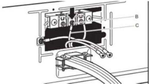
1. Prepare to connect neutral bond wire and neutral wire
Install the correct strain relief for your electrical connection method. Remove center terminal block screw (B). Remove neutral bond wire (E) from green external ground conductor screw (A).
2. Connect neutral bond wire and neutral wire
Connect neutral bond wire (E) and neutral wire (white or center wire) (C) of power supply cord or cable under center terminal block screw (B). Tighten screw.
3. Connect remaining wires
natural_image
Pure electrical circuit lines without any symbolsPlace remaining wires under outer terminal block screws. Tighten screws.
4. Connect external ground wire
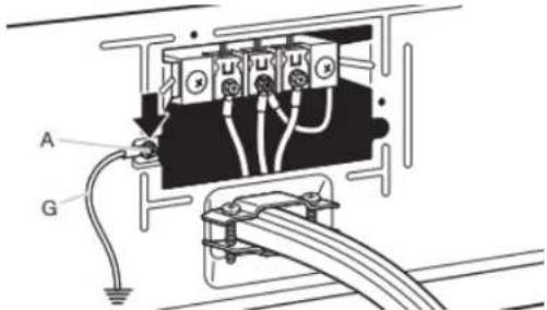
Connect a separate copper ground wire (G) from the ge external ground conductor screw (A) to an adequate grot Insert tab of terminal block cover into slot of dryer rear Secure cover with hold-down screw. Now, go to "Venting Requirements."
Home Venting Requirements
WARNING

Fire Hazard
Use a heavy metal vent.
Do not use a plastic vent.
Do not use a metal foil vent.
Failure to follow these instructions can result in death or fire.
WARNING: To reduce the risk of fire, this dryer MUST BE EXHAUSTED OUTDOORS.
IMPORTANT: Observe all governing codes and ordinances. Do exhaust must not be connected into any gas vent, chimney, wall, ceiling, attic, crawlspace, or a concealed space of a building, rigid or flexible metal vent shall be used for exhausting. Do use plastic or metal foil vent.
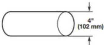
■ Only a 4" (102 mm) heavy metal exhaust vent and clamps may be used.
■ Do not use plastic or metal foil vent.
Rigid metal vent:
■ Recommended for best drying performance and to avoid crushing and kinking.
Flexible metal vent (acceptable only if accessible to clean):
■ Must be fully extended and supported in final dryer location.
■ Remove excess to avoid sagging and kinking that may result in reduced airflow and poor performance.
■ Do not install in enclosed walls, ceilings, or floors.
■ The total length should not exceed (2.4 m).
The length of flexible metal vent used must be included in the overall vent system design as shown in the "Vent System Chart."
Home Venting System:
■ If using an existing home vent system, clean lint from the entire length of the system before installing the dryer.
■ Make sure external exhaust hoods outside of the home is I plugged with lint or other outside debris.
■ Replace plastic or metal foil vents with rigid metal or flexible metal vents. Review "Vent System Chart" and, if necessary, modify existing home vent system to achieve best drying performance.
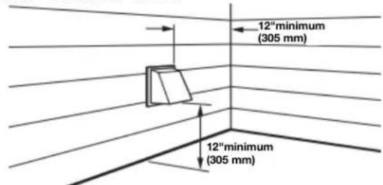
Exhaust hoods:
An exhaust hood should cap the vent to keep rodents and insects from entering the home.
■ Must be at least 12" (305 mm) from ground or any object may obstruct exhaust (such as flowers, rocks, bushes, or snow).
■ Do not use an exhaust hood with a magnetic latch.
Recommended Styles: Acceptable Style:
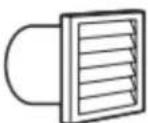
Louvered Hood

Box Hood Angled
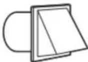
Hood
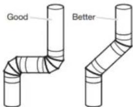
Elbows:
■ 45° elbows provide better airflow than 90° elbows.
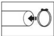
Clamps:
Dyer Use clamps to seal all joints.
■ Exhaust vent must not be connected or secured with screws. Only other fastening devices that extend into interior of duct and catch lint. Do not use duct tape.
Vent products can be purchased from your dealer. For contact ordering information, refer to your Quick Start Guide.
Plan Vent System
Recommended exhaust installations:
Typical installations vent the dryer from the rear of the installations are possible.
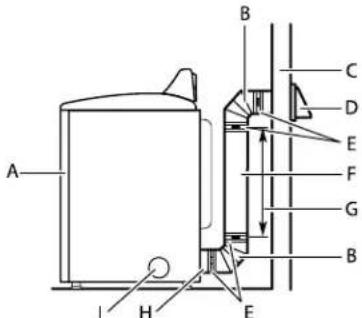
A. Dryer
B. Elbow
C. Wall
D. Exhaust hood
E. Clamps
F. Rigid metal or flexible metal vent
G. Vent length necessary to connect elbows
H. Exhaust outlet
I. Optional side exhaust outlet
Optional exhaust installations:
WARNING

Fire Hazard
Cover unused exhaust holes with a manufacturer's exhaust cover kit.
Contact your local dealer.
Failure to follow these instructions can result in death, fire, electrical shock, or serious injury.
Some models can be converted to exhaust out the right side, "Veft System Chart." Exhaust systems longer than those side, or through the bottom. If you prefer, you may contact yspecified will:
local dealer to have the dryer converted.
A
B
C
A. Standard rear offset exhaust installation
B. Left or right side exhaust installation (available only on select 27" wide models).
C. Bottom exhaust installation (available only on select 27 wide models).
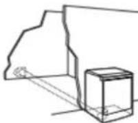
Alternate installations for close clearances
Venting systems come in many varieties. Select the type best your installation. Two close-clearance installations are shown.
NOTE: The following kits for close-clearance alternate installations are available for purchase. Refer to Quick Start Gui for contact information.
natural_image
Diagram of a portable electronic device with a coiled cable and directional arrow indicating movement (no text or symbols present)Over-The-Top installation (also available with one offset elbow)
natural_image
Line drawing of a mechanical device with a handle and internal components (no text or symbols)Periscope installation
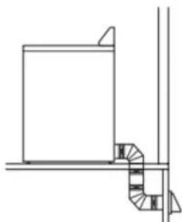
Special provisions for mobile home installations:
Exhaust vent must be securely fastened to a noncombustible portion of the mobile home and must not terminate beneath the mobile home. Terminate exhaust vent outside.
natural_image
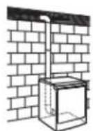
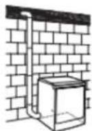
Pure architectural line drawing of a staircase and adjacent building corner (no text or symbols)Determine vent path:
■ Select route that will provide straightest and most direct path outdoors.
■ Plan installation to use fewest number of elbows and turns.
■ When using elbows or making turns, allow as much room as possible.
■ Bend vent gradually to avoid kinking.
■ Use as few 90° turns as possible.
Determine vent length and elbows needed for best drying performance:
■ Use following "Vent System Chart" to determine type of vent material and hood combinations acceptable to use.
NOTE: Do not use vent runs longer than those specified in
ide,"Veft System Chart." Exhaust systems longer than those t yspecified will:
■ Shorten life of dryer.
■ Reduce performance, resulting in longer drying times and increased energy usage.
The "Vent System Chart" provides venting requirements that will help achieve best drying performance.
| Vent System Chart | ||
| Number of 90° turns or elbows | Type of vent | Box/louvered or Angled hoods |
| 0 | Rigid metal 64 ft | (20 m) |
| 1 | Rigid metal 54 ft | (16.5 m) |
| 2 | Rigid metal 44 ft | (13.4 m) |
| 3 | Rigid metal 35 ft | (10.7 m) |
| 4 | Rigid metal 27 ft | (8.2 m) |
NOTE: Side and bottom exhaust installations have a 90° turn inside the dryer. To determine maximum exhaust length, add or 90° turn to the chart.
| Vent System Chart (29" Wide Long Vent WED/WGD4985 and WED/WGD4995 Models Only | ||
| Number of 90° turns or elbows | Type of vent Box | /louvered or Angled hoods |
| 0 Rigid metal 160 | ft (48.8 m) | |
| 1 Rigid metal 150 | ft (45.7 m) | |
| 2 Rigid metal 140 | ft (42.7 m) | |
| 3 Rigid metal 130 | ft (39.6 m) | |
| 4 Rigid metal 120 | ft (36.6 m) | |
| 5 Rigid metal 110 | ft (33.5 m) | |
NOTE: For long vent systems, use of box/louvered hoods will improve venting regardless of length.
Additional Elbows
In cases in which the Installation Instructions do not address vent length for the specific number of elbows required for a particular application, the following calculations may be used. (The total vent system length includes all straight and curved portions of the vent system):
■ For 90° elbows, reduce the allowable vent system length by 10 ft (3.05 m).
■ For 45^ elbows, reduce the allowable vent system length by 6 ft (1.83 m).
For example, if the Installation Instructions state that a dryer is allowed 40 ft (12.2 m) of total vent length with two 90° bends, the total allowable vent length would be reduced by 20 ft (6.0 m) (from 40 ft [12.2 m] to 20 ft [6.0m]).
Install Vent System
1. Install exhaust hood
Install exhaust hood and use caulking compound to seal exterior wall opening around exhaust hood.
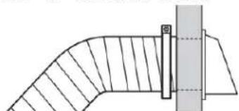
2. Connect vent to exhaust hood
natural_image
Pure architectural or engineering diagram showing a curved structure with hatched fill and a vertical support (no text or symbols)Vent must fit over the exhaust hood. Secure vent to exhaust hood with 4" (102 mm) clamp. Run vent to dryer location using straightest path possible. Avoid 90° turns. Use clamps to seal all joints. Do not use duct tape, screws, or other fastening devices that extend into interior of vent to secure vent, because they can catch lint.
Connect Inlet Hoses
For vented, non-steam models, skip to "Connect Vent." The dry must be connected to the cold water faucet using the new ink hoses. Do not use old hoses.
NOTE: Replace inlet hoses after 5 years of use to reduce the of hose failure. Record hose installation or replacement dates o the hoses for future reference.
Periodically inspect and replace hoses if bulges, kinks, cuts, we or leaks are found.
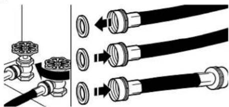
1. Turn cold water off, remove and replace rubber washer
natural_image
Diagram showing pipe fittings and valve assembly (no text or labels)the Turn cold water faucet off and remove washer inlet hose. Remove old rubber washer from inlet hose and replace with new rubber washer.
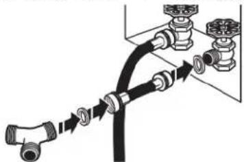
2. Attach short hose and "Y" connector
natural_image
Diagram of pipe connection with hoses and valves (no text or labels)Attach 2 ft (0.6 m) inlet hose to cold water faucet. Screw coupling by hand until it is seated on faucet. Then attach connector to male end of the 2 ft (0.6 m) inlet hose. Scr coupling by hand until it is seated on connector.
3. Tighten couplings
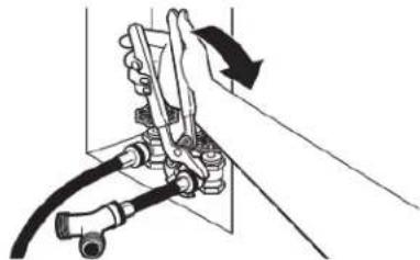
natural_image
Diagram of a hand using a tool to adjust or install a mechanical component, with no visible text or symbols.Using pliers, tighten the couplings with additional two-thirds turn.
NOTE: Do not overtighten. Damage to the coupling can result.
- Attach long hose to "Y" connector and tighten Connect Vent (Vented Models Only) couplings
- Connect vent to exhaust outlet
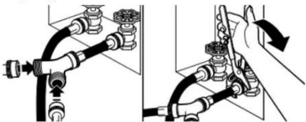
natural_image
Diagram showing two mechanical pipe connections with valve fittings and a hand adjusting a valve (no text or symbols present)Attach one of the 5 ft (1.5 m) inlet hose ends to the connector. Attach washer cold inlet hose to other side of connector. Screw on coupling by hand until it is seated connector. Using pliers, tighten the couplings an additional two-thirds turn.
NOTE: Do not overtighten. Damage to the coupling can result.
- Attach long hose to dryer fill valve and tighten coupling
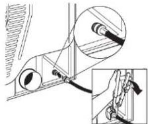
natural_image
Technical diagram of a mechanical assembly with no visible text or symbolsIf applicable, remove protective cap from water inlet valve. Attach other end of long hose to fill valve on dryer back Screw on coupling by hand until it is seated on fill valve connector. Using pliers, tighten the couplings an additional two-thirds turn.
NOTE: Do not overtighten. Damage to the coupling can result.
NOTE: The Steam Dryer water connection may be in a different location.
- Turn on cold water faucet
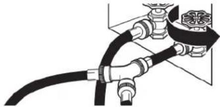
natural_image
Pure diagram of a pipe connection with no text, numbers, or symbolsCheck that the water faucet is turned on.
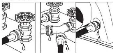
- Check for leaks
natural_image
Illustration of three different pipe fittings with water droplets, showing different installation states (no text or symbols present)Check for leaks around "Y" connector, faucets, and hoses.
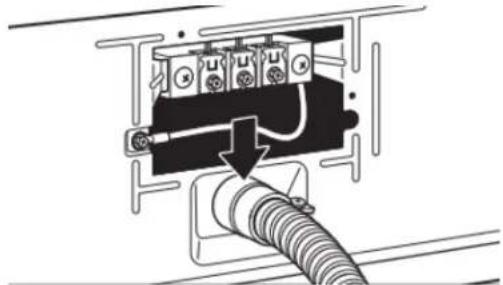
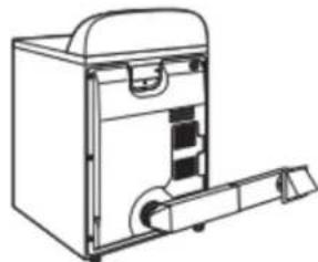
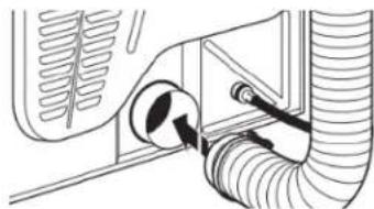
- Connect vent to exhaust outlet
natural_image
Technical line drawing of a car interior showing hoses and a valve (no text or symbols)Using a 4" (102 mm) clamp, connect vent to exhaust outlet dryer. If connecting to existing vent, make sure vent is clear. Dryer vent must fit over dryer exhaust outlet and inside
exhaust hood. Check that vent is secured to exhaust hood with a 4" (102 mm) clamp.
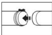
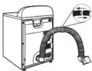
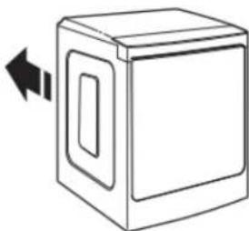
- Move dryer to final location
natural_image
Simple line drawing of a microwave oven with a double-headed arrow indicating left motion (no text or symbols)Move dryer to final location. Avoid crushing or kinking the vent. After dryer is in place, remove corner posts and cardboard from under dryer.
Level Dryer
Level Dryer
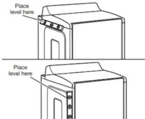
Check levelness of dryer from side to side. Repeat from fr to back.
NOTE: The dryer must be level for the moisture-sensing system to operate correctly.
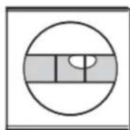
Not Level
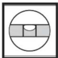
LEVEL

Not Level
2. Adjust leveling legs
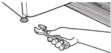
natural_image
Line drawing of a hand using a wrench to lift a pipe (no text or symbols)If dryer is not level, prop up using a wood block. Use to adjust legs up or down, and check again for level. Once dryer is level, make sure all four legs are snug the floor and the dryer does not rock.
■ For power supply cord installation, plug into a grounded out! For direct wire installation, turn on power.
If you live in a hard water area, use of a water softener recommended to control the buildup of scale through the water system in the dryer. Over time, the buildup of lime scale may clog different parts of the water system, which will reduce product performance. Excessive scale buildup may lead to the need for certain part replacement or repair.
■ To change the door swing from a right-side opening to a side opening, see online "Dryer Door Reversal Instructions" for details.
ess. Set the heat cycle for 20 minutes, and start dryer. Do not against Only temperature setting.
If the dryer will not start, check the following:
■ Controls are set in a running or "On" position.
■ Start button has been pushed firmly.
■ Dryer is plugged into an outlet and/or electrical supply.
■ Household fuse is intact and tight, or circuit breaker has tripped.
■ Dryer door is closed.
■ When the dryer has been running for 5 minutes, open the door and feel for heat. If you feel heat, cancel cycle and the door.
If you do not feel heat, turn off dryer, and check the following:
There may be 2 household fuses or circuit breakers for dryer. Check that both fuses are intact and tight, or that both circuit breakers have not tripped. If there is still no use trimeat, contact a qualified technician.
NOTE: You may notice an odor when dryer is first heated. odor is common when heating element is first used. The od will go away.
extra part If your Airflow screen reads "Check Vent," your dryer vent r be crushed or blocked.
3. Install and remove base trim (on some models)
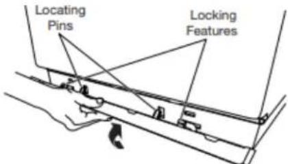
To Install: Place the skirt to bottom of dryer and match locating pins with the holes. Press the skirt firmly upwards until it snaps into place.
To Remove: On each corner, push down on top of base Rotate away from dryer and remove.
Complete Installation Checklist
■ Check that all parts are now installed. If there is an extra go back through steps to see what was skipped.
■ Check that you have all of your tools.
■ Dispose of/recycle all packaging materials.
■ Be sure the water faucets are on.
- Check for leaks around "Y" connector, faucet, and hoses.
- Check dryer's final location. Be sure vent is not crushed or kinked.
- Check that dryer is level. See "Level Dryer."
■ Remove film on console and any tape remaining on dryer.
■ Wipe dryer drum interior thoroughly with a damp cloth to remove any dust.
SÉCURITÉ DE LA SÉCHEUSE
natural_image
Four-step diagram showing hand cleaning and cleaning process: plastic tray, circular component with brush, ring, and fabric (no text or symbols)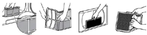
natural_image
Four-step diagram showing hand positioning and cleaning process of a device (no text or symbols)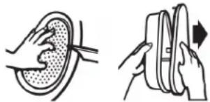
natural_image
Illustration of two hands performing a circular earbell and a ring-shaped object with an arrow indicating rotation (no text or symbols)natural_image
Illustration of five different cleaning or cleaning techniques (no text or symbols present)natural_image
Hand holding a screwdriver to switch a device from a wall socket (no text or symbols visible)natural_image
Simple line drawing of a screwdriver (no text or symbols)natural_image
Line drawing of a pair of wire crimping tools (no text or symbols)Pince à dénuder
natural_image
Simple diagram with three circular symbols inside a rectangular box (no text or labels)Niveau
natural_image
Line drawing of a pair of pliers (no text or symbols)Pince
natural_image
Simple line drawing of a measuring tape (no text or symbols)Ruban à mesurer
natural_image
Simple line drawing of a flat tool with a handle and central slot (no text or symbols)Couteau utilitaire
natural_image
Line drawing of a pliers with handle and base (no text or symbols)natural_image
Two line drawings of hand tools or pressure vessels, one cylindrical and one manual (no text or symbols)natural_image
Line drawing of an adjustable wrench (no text or symbols)natural_image
Simple line drawing of a tool or grip (no text or symbols)Couteau à mastic
natural_image
Illustration of two types of threaded fasteners, one with hexagonal nuts and the other with coiled bolts (no text or symbols)natural_image
Simple line drawing of a T-shaped pipe fitting with two threaded ends (no text or symbols)Raccord en « Y »
natural_image
Simple line drawing of a ring-shaped object (no text or symbols)natural_image
Simple black curved line with two endpoints, no text or symbols presentnatural_image
Coiled black cable or hose with two connectors (no text or symbols visible)natural_image
Two interlocked metal rings with clips attached (no text or symbols)natural_image
Technical line drawing of a mechanical housing with mounting holes and internal components (no text or symbols)natural_image
Line drawing of a front-loading washing machine (no text or symbols)Retirerlavisderetenueetlecouvercledubornier.
natural_image
Pure electrical circuit lines without any symbolsnatural_image
Pure electrical circuit lines without any symbolsnatural_image
Technical diagram of an electrical component with labeled parts (no readable text or symbols)Retirer la vis de la borne centrale (B).
natural_image
Pure electrical circuit lines without any symbolsnatural_image
Diagram of an electrical outlet with a hose and cable, no text or symbols presentnatural_image
Pure electrical circuit lines without any symbolsnatural_image
Pure electrical circuit lines without any symbolsRetirer la vis de la borne centrale (B).
natural_image
Pure electrical circuit lines without any symbolsnatural_image
Pure electrical circuit lines without any symbolsnatural_image
Diagram of a portable electronic device with a coiled cable and labeled component (no text or symbols present)