
VEA36016 - Cooktop VESTEL - Free user manual and instructions
Find the device manual for free VEA36016 VESTEL in PDF.

| Product type | Induction hob with integrated extraction system (extractor hood) |
| Brand | Vestel |
| Model | VEA36016 |
| Category | Extractor hob |
| Number of cooking zones | 4 induction zones (including one bridge zone) |
| Control type | Electronic touch |
| Required cutout dimensions (W x D) | 750 x 490 mm (depending on installation configuration) |
| Power supply | 220-240 V ~ 50/60 Hz |
| Maximum total power | Approximately 7.2 kW (depending on zones and boost) |
| Boost function | Yes, for each zone (display shows "P") |
| Bridge function | Yes, for the two left zones (merge into one large zone) |
| Smart pause | Yes, reduces power of all active zones |
| Timer | Minute timer (1-99 min) and independent zone timer (1-99 min) |
| Child lock | Controls lock with display showing "L" |
| Controls lock | Yes, activated by long press on lock key |
| Automatic safety shut-off | Yes, according to heat level (1.5 to 6 hours) |
| Residual heat indicator | Shows "H" while zone is hot |
| Air extraction unit | Integrated, with touch control and shut-off timer (15 min) |
| Metal grease filter | Cleanable every 2 weeks (by hand or dishwasher) |
| Activated carbon filter | For recirculation, regeneration in oven (200°C, 1h) or replacement every 3 months |
| Hob cleaning | Non-abrasive products, avoid steam, scrape off sugary spills immediately |
| Error codes | E1, E3-E8, EA, EC, C1-C8 (see manual for meaning) |
| Approximate weight | Approximately 18 kg (depending on configuration) |
Frequently Asked Questions - VEA36016 VESTEL
User questions about VEA36016 VESTEL
0 question about this device. Answer the ones you know or ask your own.
Ask a new question about this device
Download the instructions for your Cooktop in PDF format for free! Find your manual VEA36016 - VESTEL and take your electronic device back in hand. On this page are published all the documents necessary for the use of your device. VEA36016 by VESTEL.
USER MANUAL VEA36016 VESTEL
natural_image
Simple diagram with four geometric shapes: oval, rectangle, circle, and circle (no text or symbols)VEA36016
natural_image
Simple line drawing of a rectangular electronic component with a slot and labeled part '1' (no text or symbols beyond label)natural_image
Technical line drawing of a rectangular enclosure with mounting holes and a labeled dimension line (no text or symbols beyond the label)- STEUERBOX
2.4 DAS KOCHFELD MIT ABZUGSHAUBE INSTALLIEREN
natural_image
Line drawing of a mechanical device with an arrow indicating direction, no text or symbols present1. Metall-Fettfilter
natural_image
Simple line drawing of a rectangular object placed on a flat surface with an arrow indicating direction (no text or symbols)natural_image
Illustration of a hand using a screwdriver to adjust or install a panel of solar panels (no text or symbols present)natural_image
Technical line drawings of two solar panel components: a front panel with grid layout and a back panel with grid pattern (no text or symbols)natural_image
Symbol of a trash bin crossed with a horizontal line, no text or numbers presentnatural_image
Recycling symbol composed of three chasing arrows forming a triangle (no text or labels)1.1 ALGEMENE VEILIGHEIDSWAARSCHUWINGEN
1.2 WAARSCHUWINGEN BIJ DE INSTALLATIE
natural_image
Simple line drawing of a rectangular electronic component with a slot and labeled part '1' (no text or symbols beyond label)natural_image
Technical line drawing of a rectangular enclosure with mounting holes and a labeled dimension line (no text or symbols beyond the label)- BEDIENINGSKAST
-
Montagekit
-
Motoreenheid

2.4 INSTALLATIE VAN DE KOOKPLAAT MET AFZUIGING
WAARSCHUWING: DIT TOESTEL MOET WORDEN GEAARD.
natural_image
Technical line drawing of a mechanical device with internal components and directional arrows (no text or symbols)1. Metalen vetfilter
natural_image
Simple line drawing of a rectangular object placed on a flat surface with a pointer indicating direction (no text or symbols)natural_image
Illustration of a hand using a screwdriver to adjust or install a solar panel (no text or symbols visible)natural_image
Two types of solar panel modules shown side by side: a grid-patterned panel and a rectangular panel with black panels (no text or symbols)6. PROBLEEMOPLOSSING EN TRANSPORT
6.1 PROBLEEMOPLOSSING

2.2 PIÈCES DU PRODUIT
natural_image
Simple line drawing of a rectangular electronic component with a slot and labeled part '1' (no text or symbols beyond label)natural_image
Technical line drawing of a rectangular enclosure with mounting holes and a labeled dimension line (no text or symbols beyond the label)- BOUTON DE CONTRÔLE

2.4 INSTALLATION DE LA TABLE DE CUISSON ASPIRANTE
2.5 RACCORDEMENT ÉLECTRIQUE ET SÉCURITÉ
2.7 DIMENSIONS D'INSTALLATION
natural_image
Line drawing of a mechanical device with an arrow indicating direction (no text or symbols)natural_image
Simple line drawing of a rectangular object placed on a flat surface with an arrow indicating direction (no text or symbols)natural_image
Illustration of a hand using a screwdriver to adjust or install a solar panel (no text or symbols visible)natural_image
Two technical illustrations of solar panel modules: a front panel with grid-like slots and a back panel with grid-patterned panels (no text or symbols)natural_image
Symbol of a trash bin crossed with a diagonal line, no text or numbers presentnatural_image
Recycling symbol composed of three chasing arrows forming a triangle (no text or labels)Thank you for choosing this product.
This User Manual contains important safety information and instructions on the operation and maintenance of your appliance.
Please take the time to read this User Manual before using your appliance and keep this book for future reference.
| Icon Type Meaning | |
| WARNING Serious injury or death risk | |
| RISK OF ELECTRIC SHOCK Dangerous voltage risk | |
| FIRE Warning; Risk of fire / flammable materials | |
| CAUTION Injury or property damage risk | |
| IMPORTANT / NOTE Operating the system correctly |
CONTENTS
1.SAFETY INSTRUCTIONS....4
1.1 General Safety Warnings ....4
1.2 Installation Warnings ....6
1.3 During Use 7
1.4 During Cleaning and Maintenance 8
2.INSTALLATION AND PREPARATION FOR USE....9
2.1 Instructions for the Installer 9
2.2 Product parts ......9
2.3 Assemblying of the Air Extraction Unit 10
2.4 Installation of the Venting Hob....10
2.5 Electrical Connection and Safety....10
2.6 Power supply connection....11
2.7 Installation Dimensions.... 11
3.PRODUCT FEATURES....20
4.USE OF PRODUCT 21
4.1 Hob Controls....21
4.2 Air Extraction Unit Controls....24
5.CLEANING AND MAINTENANCE....25
5.1 Hob Cleaning....25
5.2 Cleaning the Metal Grease Filter 25
5.3 Cleaning or replacing activated charcoal filter (recirculation only) 26
5.4 Maintenance intervals....27
6.TROUBLESHOOTING&TRANSPORT 28
6.1 Troubleshooting....28
6.2 Transport 28
1. SAFETY INSTRUCTIONS
- Carefully read all instructions before using your appliance and keep them in a convenient place for reference when necessary.
- This manual has been prepared for more than one model therefore your appliance may not have some of the features described within. For this reason, it is important to pay particular attention to any figures whilst reading the operating manual.
1.1 GENERAL SAFETY WARNINGS
- This appliance can be used by children aged from 8 years and above and by persons with reduced physical, sensory or mental capabilities or lack of experience and knowledge if they have been given supervision or instruction concerning use of the appliance in a safe way and understand the hazards involved. Children should not play with the appliance. Cleaning and user maintenance should not be made by children without supervision.
WARNING: The appliance and its accessible parts become hot during use. Care should be taken to avoid touching heating elements. Keep children less than 8 years of age away unless they are continually supervised.
WARNING: Unattended cooking on a hob with fat or oil can be dangerous and may result in fire. NEVER try to extinguish such a fire with water, but switch off the appliance and cover the flame with a lid or a fire blanket.
⚠️ CAUTION: The cooking process has to be supervised. A short term cooking process has to be supervised continuously
⚠️! WARNING: Danger of fire: Do not store items on the cooking surfaces.
⚠️ WARNING: If the surface is cracked, switch off the appliance to avoid the possibility of electric shock.
- For induction hobs, metallic objects such as knives, forks, spoons and lids should not be placed on the hob surface because they can get hot.
- For induction hobs, after use switch off the hob element using the control knob. Do not rely on the pan detector.
- For models which incorporate a hob lid, clean any spillages off the lid before use and allow the cooker to cool before closing the lid.
- Do not operate the appliance with an external timer or separate remote-control system.
- Do not use harsh abrasive cleaners or scourers to clean oven surfaces. They can scratch the surfaces which may result in shattering of the door glass or damage to surfaces.
- Do not use steam cleaners for cleaning the appliance.
- Your appliance is produced in accordance with all applicable local and international standards and regulations.
- Maintenance and repair work should only be carried out by authorised service technicians. Installation and repair work that is carried out by unauthorised technicians may be dangerous. Do not alter or modify the specifications of the appliance in any way. Inappropriate hob guards can cause accidents.
- Before connecting your appliance, make sure that the local distribution conditions (nature of the gas and gas pressure or electricity voltage and
frequency) and the specifications of the appliance are compatible. The specifications for this appliance are stated on the label.
⚠️ CAUTION: This appliance is designed only for cooking food and is intended for indoor domestic household use only. It should not be used for any other purpose or in any other application, such as for non-domestic use, in a commercial environment or for heating a room.
- All possible measures have been taken to ensure your safety. Since the glass may break, care should be taken while cleaning to avoid scratching. Avoid hitting or knocking the glass with accessories.
- Make sure that the supply cord is not trapped or damaged during installation. If the supply cord is damaged, it must be replaced by the manufacturer, its service agent or similarly qualified persons in order to prevent a hazard.
- Please keep children and animals away from this appliance.
- When the induction hob is in use, keep the objects that are sensitive to magnetic fields (such as credit cards, bank cards, watches, and similar items) away from the hob. It is strongly suggested that anyone with a pacemaker should consult their cardiologist before using the induction hob.
1.2 INSTALLATION WARNINGS
- Do not operate the appliance before it is fully installed.
-
The appliance must be installed by an authorised technician. The manufacturer is not responsible for any damage that might be caused by defective placement and installation by unauthorised people.
-
When the appliance is unpacked, make sure that it is has not been damaged during transportation. In the case of a defect do not use the appliance and contact a qualified service agent immediately. The materials used for packaging (nylon, staplers, Styrofoam, etc.) may be harmful to children and they should be collected and removed immediately.
- Protect your appliance against atmospheric effects. Do not expose it to effects such as sun, rain, snow, dust or excessive humidity.
- Materials around the appliance (i.e. cabinets) must be able to withstand a minimum temperature of 100°C.
- The temperature of the bottom surface of the hob may rise during operation, therefore a board must be installed underneath the product.
1.3 DURING USE
- Do not put flammable or combustible materials in or near the appliance when it is operating.
Do not leave the cooker unattended while cooking with solid or liquid oils. They may catch fire under extreme heating conditions. Never pour water on to flames that are caused by oil, instead switch the cooker off and cover the pan with its lid or a fire blanket.
- If the product will not be used for a long period of time, turn the main control switch off. Turn the gas valve off when a gas appliance is not in use.
- Always position pans over the centre of the cooking zone, and turn the handles to a safe position so they cannot be knocked or grabbed.
- Make sure the appliance control knobs are always in the “0” (stop) position when it is not in use.
1.4 DURING CLEANING AND MAINTENANCE
- Make sure that your appliance is turned off at the mains before carrying out any cleaning or maintenance operations.
- Do not remove the control knobs to clean the control panel.
- To maintain the efficiency and safety of your appliance, we recommend you always use original spare parts and to call our authorised service agents in case of need.
Disposal of your old machine
This symbol on the product or on its packaging indicates that this product should not be treated as household waste. Instead it should be handed over to the applicable collection point for the recycling of electrical and electronic equipment. By ensuring this product is disposed of correctly, you will help prevent potential negative consequences for the environment and human health, which could otherwise be caused by inappropriate waste handling of this product. For more detailed information about recycling of this product, please contact your local city office, your household waste disposal service or the retailer who you purchased this product from.
2. INSTALLATION AND PREPARATION FOR USE

WARNING: This appliance must be installed by an authorised service person or qualified technician, according to the instructions in this guide and in compliance with the current local regulations.
- Incorrect installation may cause harm and damage, for which the manufacturer accepts no responsibility and the warranty will not be valid.
- Prior to installation, ensure that the local distribution conditions (electricity voltage and frequency and/or nature of the gas and gas pressure) and the adjustments of the appliance are compatible. The adjustment conditions for this appliance are stated on the label.
- The laws, ordinances, directives and standards in force in the country of use are to be followed (safety regulations, proper recycling in accordance with the regulations, etc.).
2.1 INSTRUCTIONS FOR THE INSTALLER General instructions
• After removing the packaging material from the appliance and its accessories, ensure that the appliance is not damaged. If you suspect any damage, do not use it and contact an authorised service person or qualified technician immediately.
- Make sure that there are no flammable or combustible materials in the close vicinity, such as curtains, oil, cloth etc. which may catch fire.
- The worktop and furniture surrounding the appliance must be made of materials resistant to temperatures above 100°C.
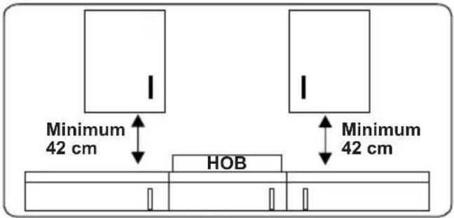
- If a cupboard is to be installed above the appliance, the safety distance between cooktop and any cupboard should be as shown below.
- The appliance should not be installed directly above a dishwasher, fridge, freezer, washing machine or clothes dryer.
- If the base of the appliance is accessible by hand, a barrier made from a suitable material must be fitted below the base of the appliance, ensuring that there is no access to the base of the appliance.
• Make sure that the induction hob is well ventilated and the air inlet and outlet are not blocked.
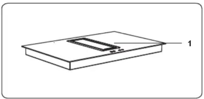
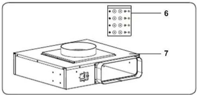
2.2 PRODUCT PARTS
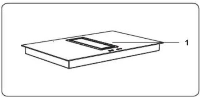
natural_image
Simple line drawing of a rectangular electronic component with a slot and labeled part '1' (no text or symbols beyond label)1. Induction hob
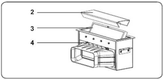
- Filter cover
- Metal gerase filter
- Air extraction unit
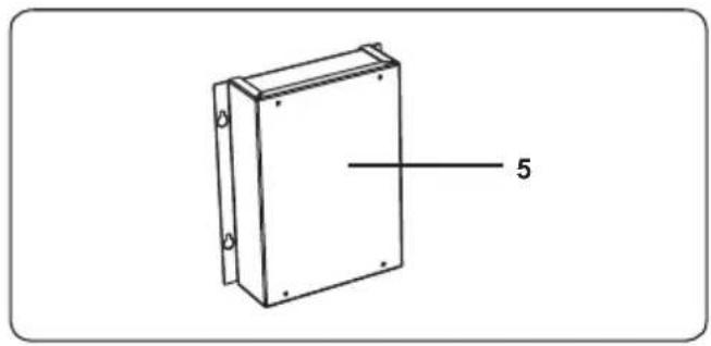
natural_image
Technical line drawing of a rectangular enclosure with mounting holes and a labeled dimension line (no text or symbols beyond the label)- CONTROL BOX
-
Assembling kit
-
Motor unit
-
Activated charcoal filter housing
-
Activated charcoal filter
-
Activated charcoal filter cover
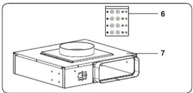
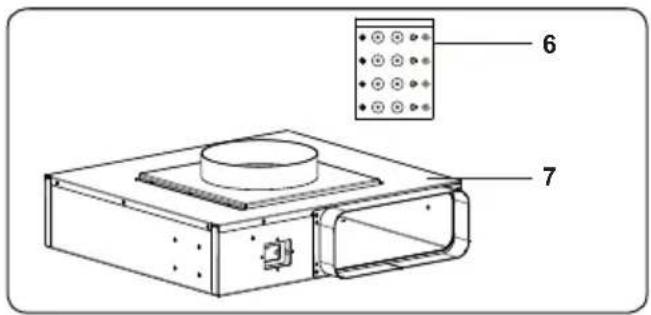
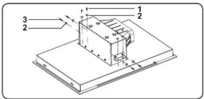
2.3 ASSEMBLYING OF THE AIR EXTRACTION UNIT
Assemble the air extraction unit towards the induction hob bottom cover. Use firstly the screws (1) and washers (3), then the screws (1) and the washers (3) included in the assembling kit.
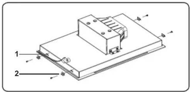
2.4 INSTALLATION OF THE VENTING HOB
The appliance is supplied with an installation kit including adhesive sealing material, fixing brackets and screws.
- Apply the supplied one-sided self-adhesive sealing tape "1" all the way around the lower edge of the cooktop. Do not stretch the tape.
- Screw the 4 worktop mounting brackets "2" in to the side walls of product.
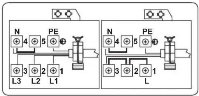
2.5 ELECTRICAL CONNECTION AND SAFETY
WARNING: The electrical connection of this appliance should be carried out by an authorised service person or qualified electrician, according to the instructions in this guide and in compliance with the current local regulations.
WARNING: THE APPLIANCE MUST BE EARTHED.
- Before connecting the appliance to the power supply, the voltage rating of the appliance (stamped on the appliance identification plate) must be checked for correspondence to the available mains supply voltage, and the mains electric wiring should be capable of handling the appliance's power rating (also indicated on the identification plate).
- During installation, please ensure that isolated cables are used. An incorrect connection could damage your appliance. If the mains cable is damaged and needs to be replaced this should be done by a qualified person.
- Do not use adaptors, multiple sockets and/or extension leads.
- The supply cord should be kept away from hot parts of the appliance and must not be bent or compressed. Otherwise the cord may be damaged, causing a short circuit.
- If the appliance is not connected to the mains with a plug, a all-pole
disconnector switch (with at least 3 mm contact spacing) must be used in order to meet the safety regulations.
- The fused switch must be easily accessible once the appliance has been installed.
- Ensure all connections are adequately tightened.
• Fix the supply cable in the cable clamp and then close the cover. - The terminal box connection is placed on the terminal box.
flowchart
graph TD
    subgraph Left_Circuit
        N1["+"] --> L3["+"]
        PE1["+"] --> L2["+"]
        PE2["+"] --> L1["+"]
        PE3["+"] --> L3
        PE4["+"] --> L2
        PE5["+"] --> L1
    end
    subgraph Right_Circuit
        N2["+"] --> L4["+"]
        PE2["+"] --> L3
        PE3["+"] --> L2
        PE4["+"] --> L1
        PE5["+"] --> L3
        PE6["+"] --> L2
        PE7["+"] --> L1
    end
    style Left_Circuit fill:#f9f,stroke:#333
    style Right_Circuit fill:#bbf,stroke:#333
2.6 POWER SUPPLY CONNECTION
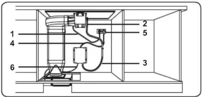
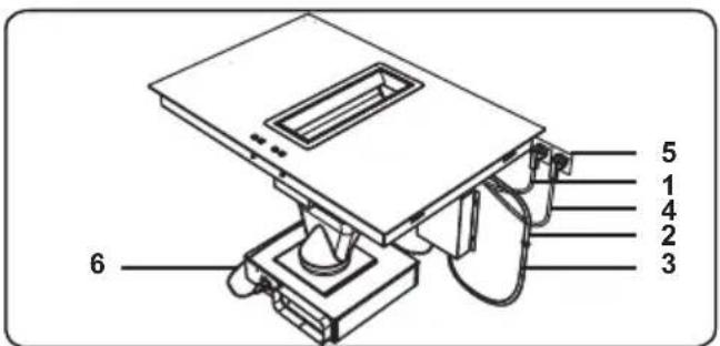
For establishing the power supply connection for the appliance;
- Connect the air extraction control unit data cable (2) with the data cable from the control box (3).
- Plug the main cable of the hob (1) into the socket (5).
- Plug the main cable of the control box (4) into the socket (5).
- Plug the motor connection cable (6) from the control box into the socket on the motor unit.
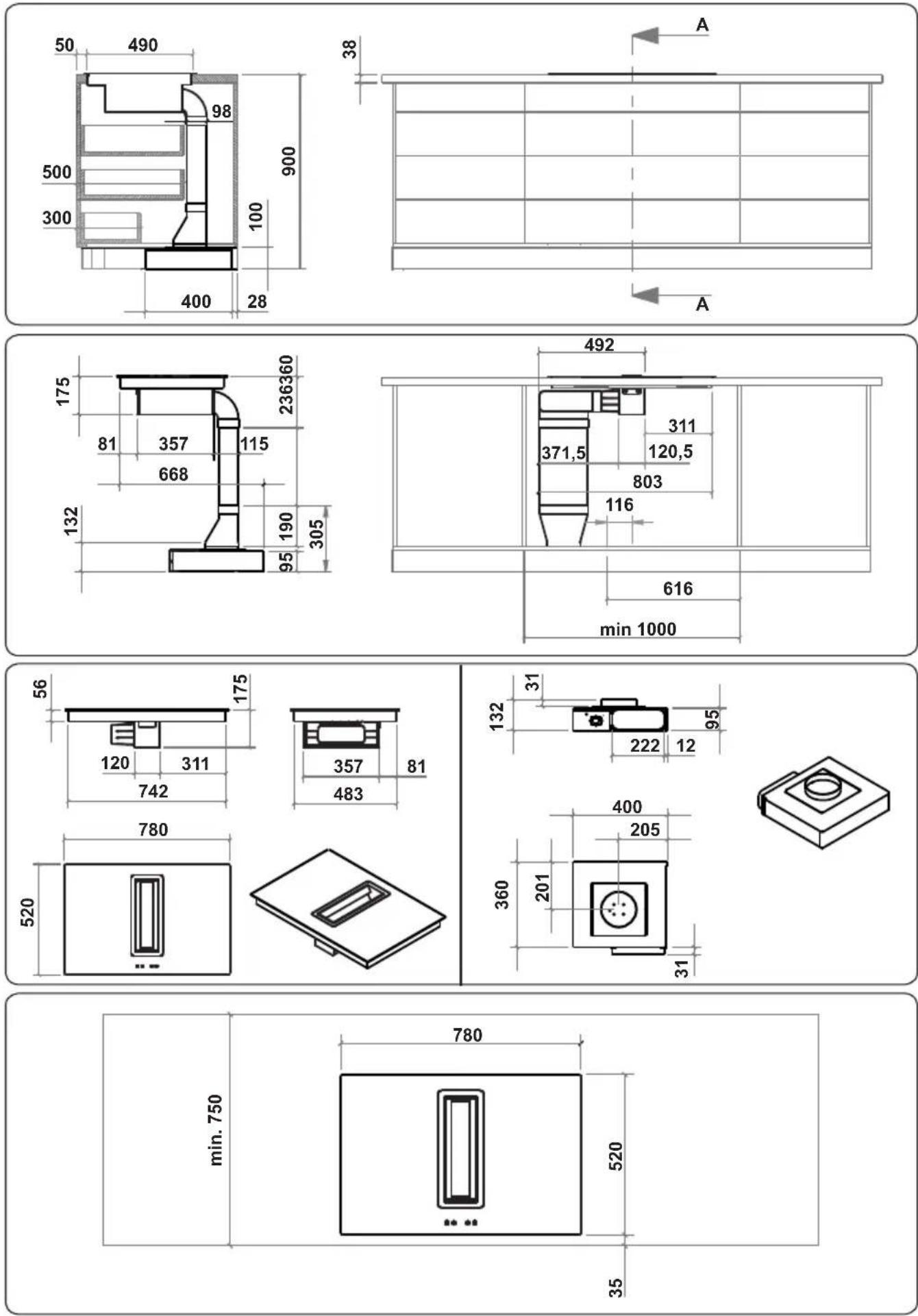
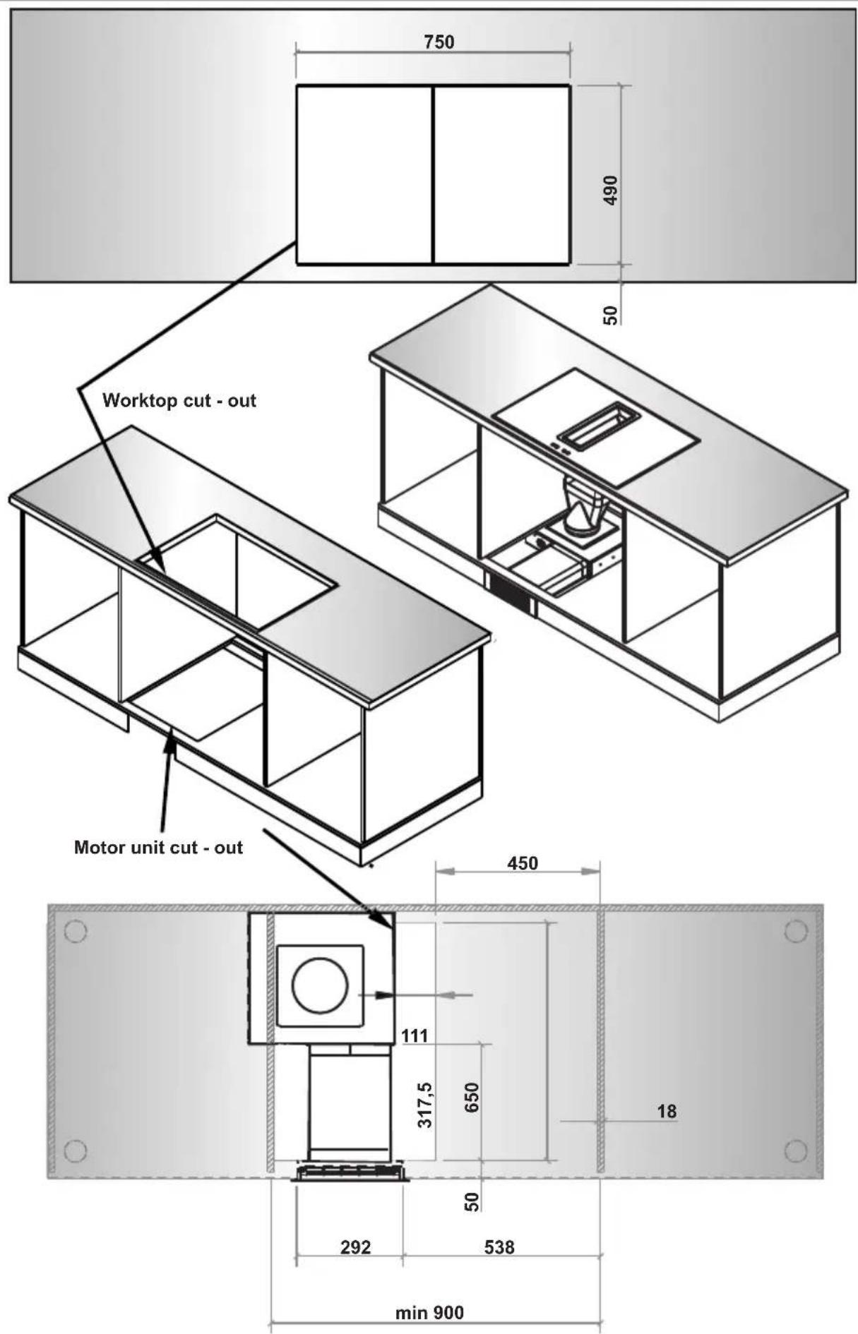
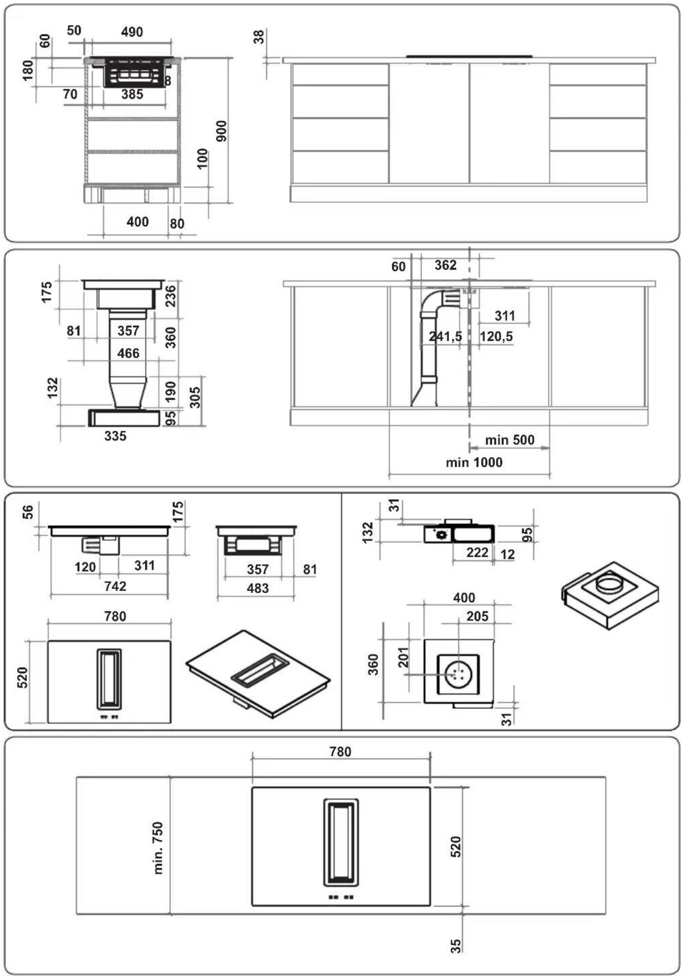
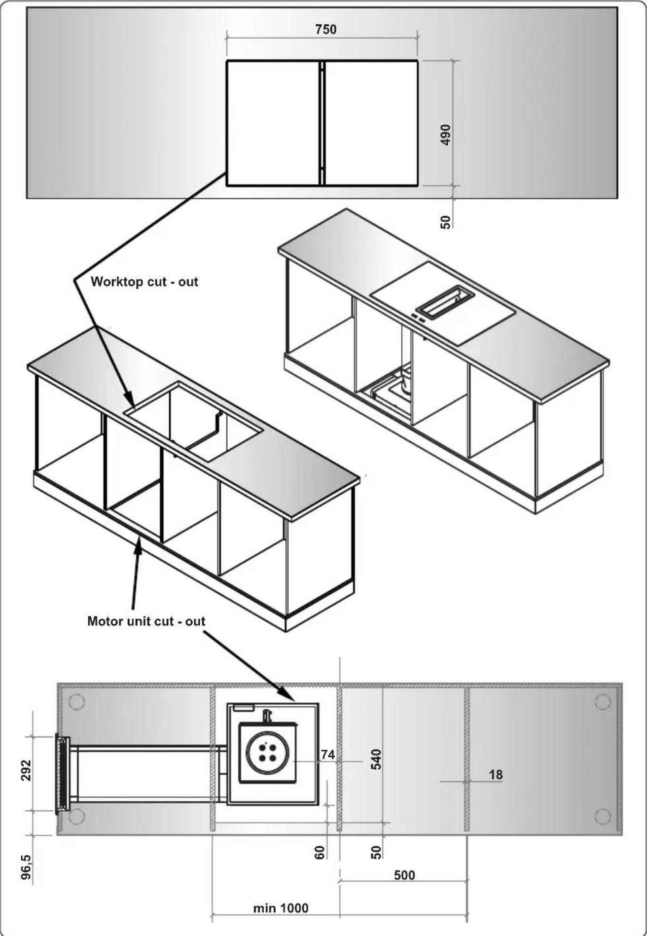
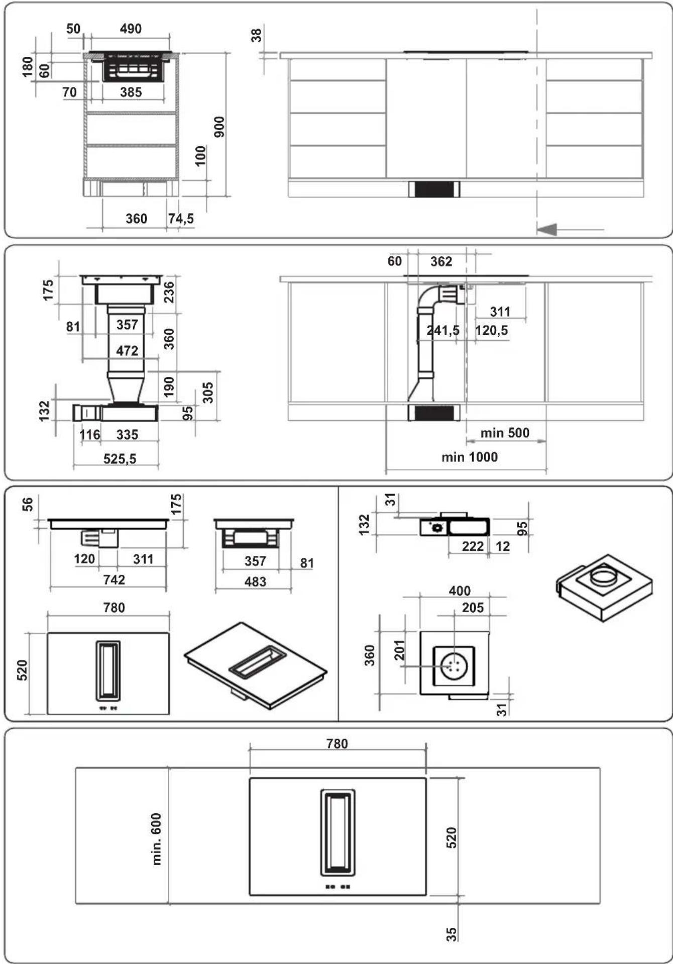
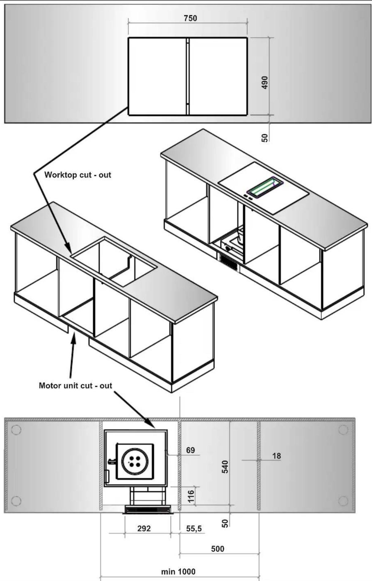
2.7 INSTALLATION DIMENSIONS
- Cut the aperture dimensions as indicated in the figure. Locate the aperture on the worktop so that, after the hob is installed, the following requirements are followed.
Island worktop installation (side outlet)
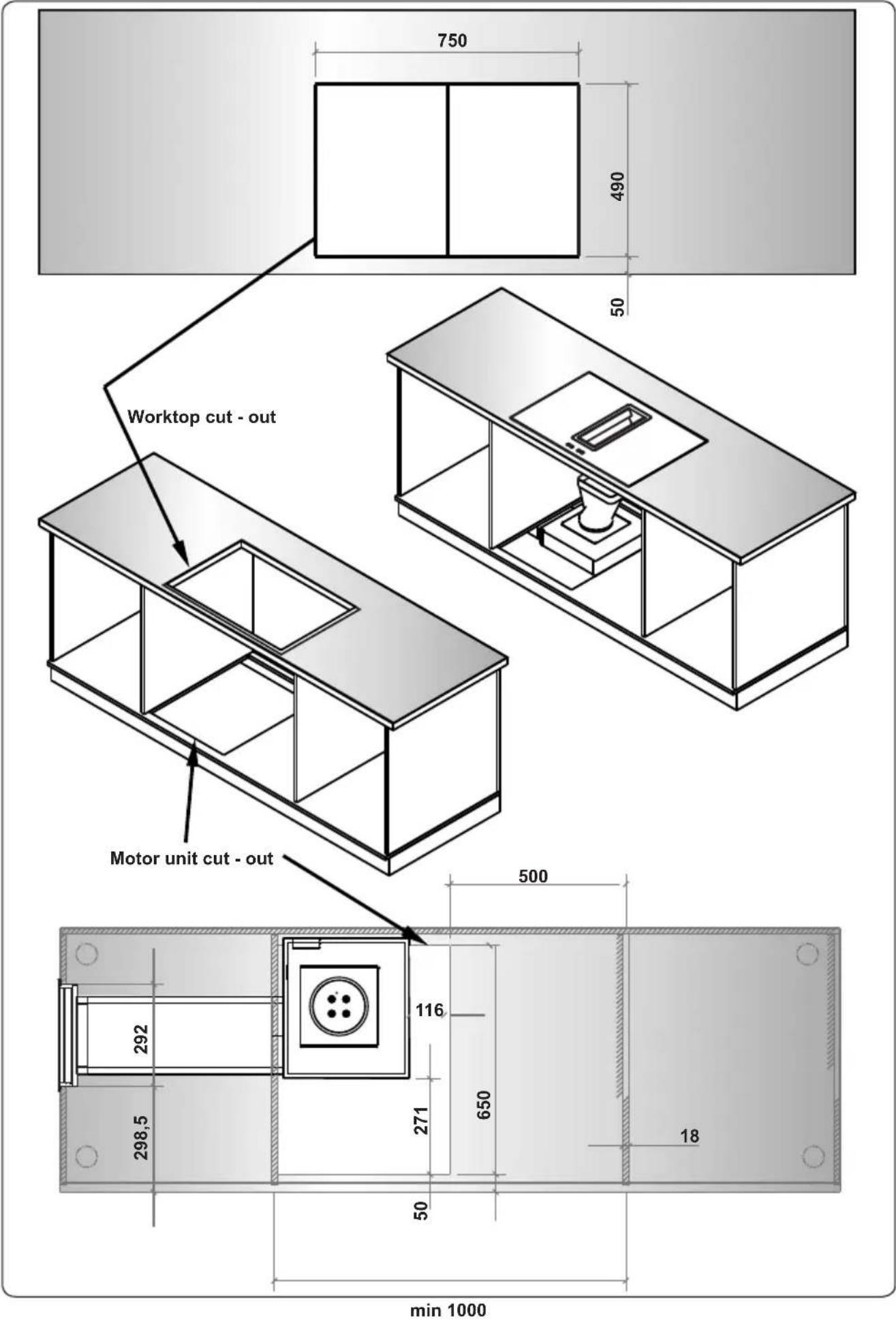
EN - 13
Island worktop installation (frontal outlet)
Standard 60 cm worktop installation (side outlet)
Standard 60 cm worktop installation (frontal outlet)
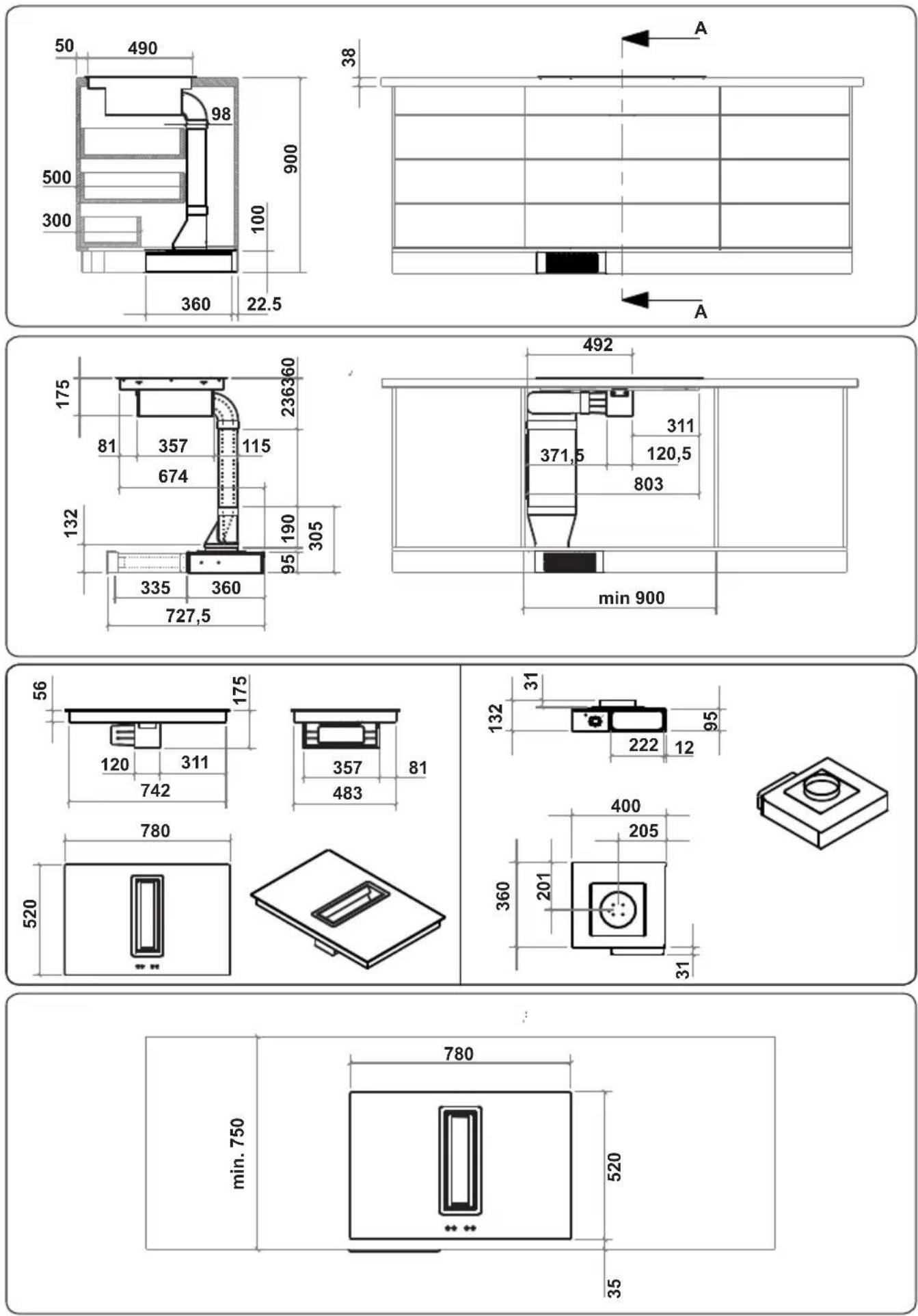
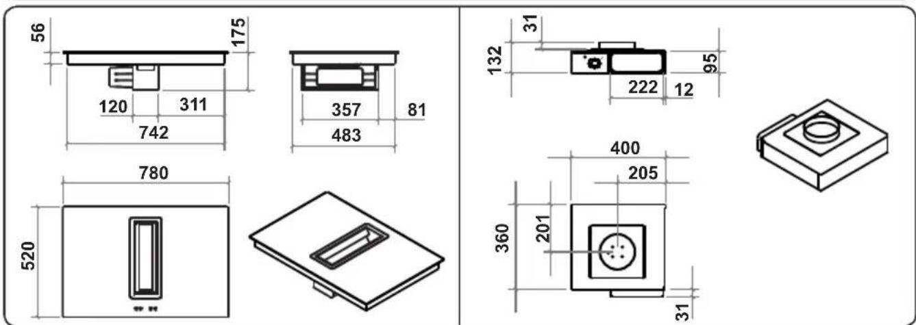
3. PRODUCT FEATURES

Important: Specifications for the product vary and the appearance of your appliance may differ from that shown in the figures below.
List of Components
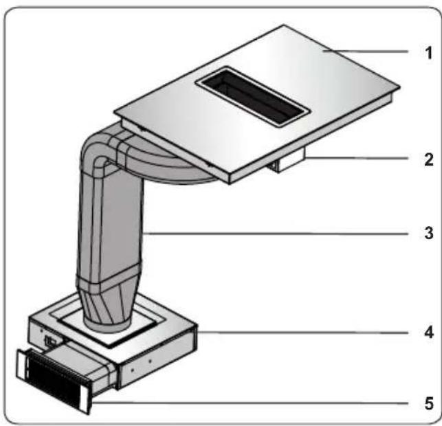
- Induction Hob
- Air extraction unit
- Piping
- Motor unit
- Activated charcoal filter
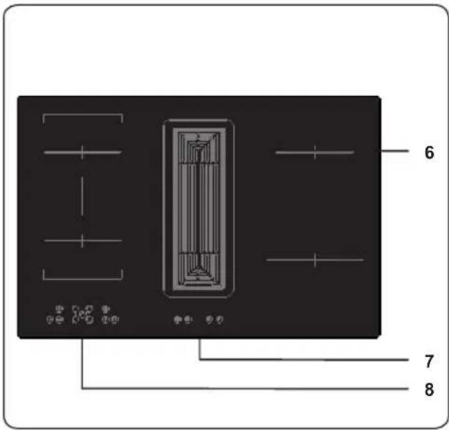
- Induction Zone
- Air Extraction Unit Control Panel
- Hob Control Panel
4. USE OF PRODUCT
4.1 HOB CONTROLS
Induction Zone
The information given in the following table is for guidance only.
| Settings Use for | |
| 0 Element off | |
| 1-3 Delicate warming | |
| 4-5 Gentle simmering, slow warming | |
| 6-7 Reheating and rapid simmering | |
| 8 Boiling, saute and searing | |
| 9 Maximum heat | |
| P Boost function |
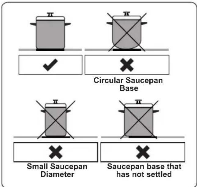
Cookware
- Use thick, flat, smooth bottomed good quality cookware made of steel, enamelled steel, cast iron or stainless steel. The quality and composition of the cookware has a direct affect on cooking performance.
- Cookware with enamelled steel, aluminium or copper bottoms can cause a metallic residue to remain on the hob. If left, this becomes difficult to remove. Clean the hob after every use.
- Cookware is suitable for induction cooking if a magnet sticks to the bottom of it.
- Cookware must be placed centrally on the cooktop. If it is not placed correctly, is displayed.
- When using certain pans, you may hear various noises coming from them, this is due to the design of the pans and does not effect the performance or safety of the hob.
- The minimum cookware diameter that the elements can detect is Q110mm for 160mm - 210mm hobs and Q160mm for a 290mm hob. Cooking performance is improved with a larger cooking area.
The appliance is operated by pressing buttons and the functions are confirmed by displays and audible sounds.
Touch Control Unit
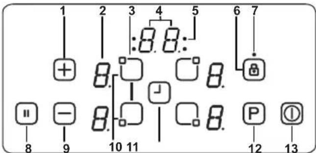
1- Increase heat setting/timer
2- Heater display
3- Heater selection
4- Timer display
5- Timer function cooking zone indicators
6- Key lock
7- Key lock indicator
8- Smart pause
9- Decrease Heat setting/Timer
10- Bridge Heater selection
11- Timer selection
12- Boost
13- On/Off
Use the induction cooking zones with suitable cookware.
After mains voltage is applied, all displays are illuminated briefly. After this, the hob is in stand-by mode and ready for operation.
The hob is controlled by pressing the
appropriate electronic button. Each button pressed is followed by a buzzer sound.
Switching the Hob On
Switch the hob on by pressing the ON/OFF button ⚠ All heater displays will show a static “0” and the bottom right dots blink. (If a cooking zone is not selected within 20 seconds, the hob will automatically switch off).
Switching the Hob Off
Switch the hob off at any time by pressing ①.
The ON/OFF button always has priority over the switch-off function.
Switching the Cooking Zones On
Press the heater selection button that corresponds to the heater you wish to use. A static dot will be shown on the selected heater display and the blinking dots on all other heater displays will no longer illuminate.
Select the temperature setting by using the increase heat setting button ☐ decrease heat setting button ☑ The element is now ready to use. For faster boil times, select the desired cooking level, then touch the 'P' button to activate the Boost function.
Switching the Cooking Zones Off
Select the element you want to switch off by pressing the heater selection button. Using the button, turn the temperature down to "0". (Pressing the end buttons simultaneously also turns the temperature to "0").
If the cooking zone is hot, "H" will be displayed instead of "0".
Switching all Cooking Zones Off
To switch all the cooking zones off at once, press the key.
In the stand-by mode, a "H" will appear on all cooking zones which are hot.
Residual Heat Indicator
The residual heat indicator indicates that the glass ceramic area has a temperature that is dangerous to touch.
After switching off the cooking zone, the respective display will show "H" until the corresponding cooking zone temperature is at a safe level.
Bridge Zone
Switching the Bridge Zone On
Press the front left and rear left heater selection buttons simultaneously. A static dot will be shown on the left heater display. The other displays will show 'b' and 'r' and the blinking dots will no longer be displayed.
Select the temperature required by using the increase heat setting button or decrease heat setting button. The bridge element will be ready to use. For the fastest boil time, select the desired cooking level, then press the "P" key to activate the Boost function.
Switching the Bridge Zone Off
To select the Bridge element, press the rear left or front left heater selection button and using the +button, turn the level down to "0". Alternatively, pressing the -and + keys simultaneously will change the level to "0".
If the bridge cooking zone is hot, "H" will be displayed.
Smart Pause
Smart Pause, when activated, reduces the power of all burners that have been switched on.
If you then deactivate the Smart Pause, the heaters will automatically return to the previous temperature level.
If the Smart Pause is not de-activated, the cooktop will switch off after 30 minutes.
Press ☐to activate Smart Pause. The power for the activated heater(s) will reduce to level 1 and "II" will appear at all displays.
Press "again to deactivate Smart Pause. "II" will disappear and the heaters will now run at the level previously set.
Safety Switch-Off Function
A cooking zone will automatically switch off if the heat setting has not been modified for a specified duration of time. A change in the heat setting of the cooking zone will reset the time duration to the initial value. This initial value depends on the selected temperature level, as shown below.
| Heat setting Safety switch off after | |
| 1-2 6 Hours | |
| 3-4 5 Hours | |
| 5 4 Hours | |
| 6-9 1.5 Hours | |
Child Lock
After switching on the appliance, the child lock function can be activated. To activate the child lock, simultaneously press the increase heat setting button Ⓤend
decrease heat setting button and then press the increase heat setting key again. "L" indicating LOCKED will appear on all heater displays and the controls can not be used. (If a cooking zone is in the hot condition, "L" and "H" will display alternately).
The hob will remain in a locked condition until it is unlocked, even if the appliance has been switched off and on.
To deactivate the child lock, first switch on the hob. Simultaneously press the increase heat setting button + and decrease heat setting button - and then press the decrease heat setting button - again. "L" will no longer be displayed and the hob will switch off.
Key Lock
The key lock function is used to set ‘safe mode’ on the appliance during operation. It will not be possible to make any adjustments by touching the buttons (for example heat settings). It will only be possible to switch the appliance off.
The lock function is active if the key lock button Ⓐ is pressed for at least 2 seconds. This operation is acknowledged by a buzzer. After successful operation, the key lock indicator will flash and the heater will be locked.
Timer Function
The timer function is available in two versions, as follow.
Minute Minder Timer (1 - 99 min.)
The minute minder timer can be operated if the cooking zones are switched off. The timer display will show "00" with a blinking dot.
Press ⊕ to increase the time or press ⊖ to decrease the time. The range is between 0 and 99 minutes. If there is no adjustment to the displayed time within 10 seconds, the minute minder timer will be set and the blinking dot will disappear. Once the timer is set, it begins to count down.
When the timer reaches zero, a signal will sound and the timer display will blink. The sound signal will stop automatically after 2 minutes and/or by pressing any button.
The minute minder timer can be changed or switched off at any time by using the timer setting button ⏻ and/or the decrease timer button ⏻ Switching off the hob by pressing ⏻ at any time will also switch off the minute minder timer.
Cooking Zone Timer (1 - 99 min.)
When the hob is switched on, an independent timer can be programmed for every cooking zone.
Select a cooking zone, then select the temperature setting and, finally, activate the timer setting button ⏻, the timer can be programmed to switch off a cooking zone. Four LEDs are arranged around the timer that indicate which cooking zone the timer has been set for.
10 seconds after the last operation, the timer display will change to the timer that will run out next (in cases where a timer is set for more than one cooking zone).
When the timer has run down, a signal will sound, the timer display will show "00" and the assigned cooking zone timer LED will blink. The programmed cooking zone will switch off and "H" will be displayed if the cooking zone is hot.
The sound signal and the blinking of the timer LED will stop automatically after 2 minutes and/or by pressing any button.
Buzzer
While the hob is in operation, the following activities will be signalled by the buzzer.
- Normal button activation will be accompanied with a short sound signal.
- Continuous button operation over a longer period of time (10 seconds) will be accompanied with a longer, intermittent sound signal.
Boost Function
To use this function, select a cooking zone and set the desired cooking level, then press the "P" (Boost) button.
The Boost function can only be activated if it is applicable with the cooking zone selected. If the Boost Function is active, a "P" is shown on the corresponding display.
Activating the booster can exceed the maximum power, in which case the integrated power management will be activated.
The necessary power reduction is shown by the corresponding cooking zone display blinking. Blinking will be active for 3 seconds to allow for further adaptations of the settings before power reduction.
| Error Codes | |
| If there is an error, an error code will be shown on the heater displays. | |
| E1 Cooling Fan is disabled. Call an authorised service agent. | |
| E3 Supply voltage is other than the rated values.Switch the hob off by pressing ➊, wait until “H” disappears for all zones, switch the hob on by pressing ➊ and continue to use. If the same error is displayed again, call an authorised service agent. | |
| E4 Supply frequency is different from the rated values. Switch the hob off by pressing ➊, wait until “H” disappears from all zones, switch the hob on by pressing ➊ and continue to use. If the same error is displayed again, switch the plug for the appliance off and on. Switch the hob on by pressing ➊ and continue to use. If the same error is displayed again, call an authorised service agent. | |
| E5 Internal temperature of the hob is too high, switch the hob off by pressing ➊ and let the heaters cool down. | |
| E6 Communication error between the touch control and heater. Call an authorised service agent. | |
| E7 Coil temperature sensor is disabled. Call an authorized service agent. | |
| E8 Cooler temperature sensor is disabled. Call an authorized service agent. | |
| EA Large Coil Saturation Error. Switch the hob off by pressing on/off button, switch the hob on by pressing on/off button and continue to use. If the same error is displayed again, call an authorised service agent. | |
| EC Supply Voltage Error.Switch the hob off by pressing on/off button, switch the hob on by pressing on/off button and continue to use. If the same error is displayed again, call an authorised service agent. | |
| C1-C8 Microprocessor alert. Switch the hob off by pressing on/off button, switch the hob on by pressing on/off button and continue to use. If the same error is displayed again, call an authorised service agent. |
4.2 AIR EXTRACTION UNIT CONTROLS
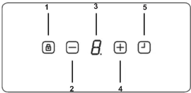
1- Air extraction unit On/Off
2- Decrease fan level setting
3- Fan level display
4- Increase fan level setting
5- Timer selection
Switching the Air Extraction Unit On-Off
When the device is not in operation, the digital display □ is in standby mode and appears as a dot. As soon as any button is pressed, a flashing “L” (i.e. lock) appears 3 times on the digital display.
After that, press and hold down the timer button until "0" appears on the digital display.
The fan has been unlocked.
After unlocking the fan, you can use the “+” and “-” buttons to set the speed of the fan.
Now setting up the fan operation speed is completed.
Switching the Air Extraction Unit Fan Level On
Increase the fan speed by pressing the button “+”. Fan level has been increased.
Switching the Air Extraction Unit Level Off
Decrease the fan speed by pressing the button “-”. Fan level has been decrease.

If for 10 minutes, no button has been pressed, the device will switch into the standby mode and get locked.

To turn off the fan, press the button until "0" appears on the digital display.
Timer Function
If while the device is running on any level, the button is pressed, the 15 minutes timer will be activated. As soon as the timer starts counting down, the speed value on the digital display will start flashing. After 15 minutes, all functions that were activated prior to the timer, will shut down.
Press the Timer button 📁.
Delayed shut-off automatic has been activated. The fan will automatically shut down after 15 minutes.

When the delayed shut-off automatic has been activated, the speed value on the digital display will start flashing.
Press the sensor button 📁 again.
Delayed shut-off automatic has been deactivated.
Filter Cleaning Message
When the “C” digital screen is displayed, the metal grease filter must be cleaned. To delete the metal grease filter cleaning prompt, proceed as follows:
After the cleaning has been completed “-” press the button, until “E” appears on the screen.
Now the metal grease filter cleaning prompt has been deleted.
5. CLEANING AND MAINTENANCE
5.1 HOB CLEANING

WARNING: Switch off the appliance and allow it to cool before cleaning is
to be carried out.
General Instructions
- Check whether the cleaning materials are appropriate and recommended by the manufacturer before use on your appliance.
- Use cream cleaners or liquid cleaners which do not contain particles. Do not use caustic (corrosive) creams, abrasive cleaning powders, rough wire wool or hard tools as they may damage the cooker surfaces.

Do not use cleaners that contain particles, as they may scratch the glass, enamelled and/or painted parts ur appliance.
- Should any liquids overflow, clean them immediately to avoid parts becoming damaged.

Do not use steam cleaners for cleaning any part of the appliance.
Cleaning the Ceramic Glass
Ceramic glass can hold heavy utensils but may be broken if it is hit with a sharp object.

WARNING : Ceramic Cooktops - if the surface is cracked, to avoid the possibility of an electric shock, switch e appliance and call for service.
- Use a cream or liquid cleaner to clean the vitroceramic glass. Then, rinse and dry them thoroughly with a dry cloth.

Do not use cleaning materials meant
for steel as they may damage the glass.
- If substances with a low melting point are used in the cookware's base or coatings, they can damage the glass-ceramic cooktop. If plastic, tin foil, sugar or sugary foods have fallen on the hot glass-ceramic cooktop, please scrape it off the hot surface as quickly and as safely as possible. If these substances melt, they can damage the glass-ceramic cooktop. When you cook very sugary items like jam, apply a layer of a suitable protective agent beforehand if it is possible.
- Dust on the surface must be cleaned with a wet cloth.
- Any changes in colour to the ceramic glass will not affect the structure or durability of the ceramic and is not due to a change in the material.
Colour changes to the ceramic glass may be for a number of reasons:
- Spilt food has not been cleaned off the surface.
- Using incorrect dishes on the hob will erode the surface.
- Using the wrong cleaning materials.
Cleaning the Stainless Steel Parts (if available)
- Clean the stainless steel parts of your appliance on a regular basis.
- Wipe the stainless steel parts with a soft cloth soaked in only water. Then, dry them thoroughly with a dry cloth.

Do not clean the stainless steel parts while they are still hot from cooking.

Do not leave vinegar, coffee, milk, salt, water, lemon or tomato juice on the stainless steel for a long time.
5.2 CLEANING THE METAL GREASE FILTER
WARNING: Fire hazard due to grease and fat residues inside the metal grease filter!
There is a risk of fire due to fatty deposits in the metal grease filter!
- Clean the metal grease filter as soon as the instruction for cleaning the filter appears or at least every 2 weeks.
- Never operate the extractor without the metal grease filter.
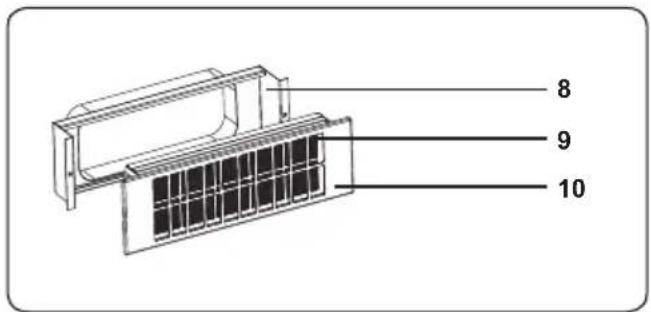
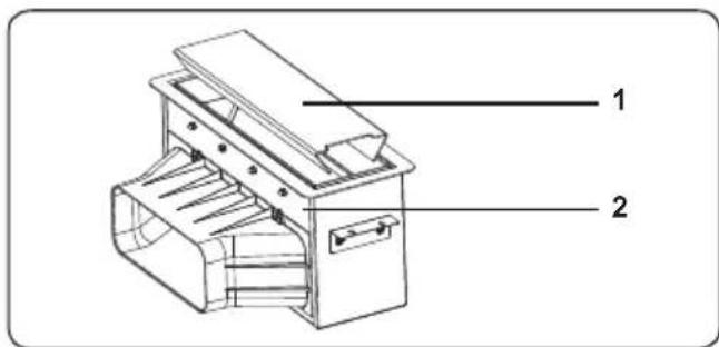
Remove the metal grease filter
-
Filter cover
-
Air extraction unit
natural_image
Technical line drawing of a mechanical device with internal components and directional arrows (no text or symbols)-
Metal grease filter
-
Remove the metal grease filter (1) by moving it in the direction of the arrow. Make sure the metal grease filter does not fall off.
- Lay the metal grease filter forward and remove it.
- Rinse the metal grease filter by hand or in the dishwasher.
Manual Cleaning

Damage due to incorrect cleaning or due to the use of unsuitable cleaning agents!
- Let the metal grease filter soak in warm soap water and clean it using a soft brush.
- Rinse with water the metal grease filter with warm water.
- Place the metal grease filter loosely and vertically without adding other tableware into the dishwasher.
- Start any program with a temperature of no higher than 55°C.
- Due to the cleaning in the dishwasher, the filter parts may experience slight changes in their colour. This does not affect function or performance to the metal grease filter.
After cleaning
Put the metal grease filter on an absorbent pad.
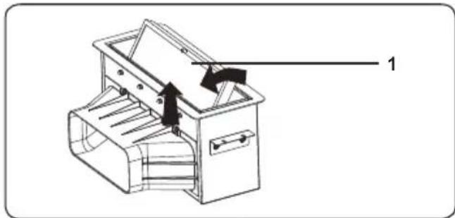
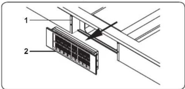
Inserting the metal grease filter
natural_image
Technical line drawing of a mechanical device with labeled component '1' (no text or symbols beyond label)-
Metal grease filter
-
Move the metal grease filter in the direction of the arrow and insert it into the air extraction duct.
- Clearing the warning for cleaning the metal grease filter.
- Close the filter cover of the air extraction unit.
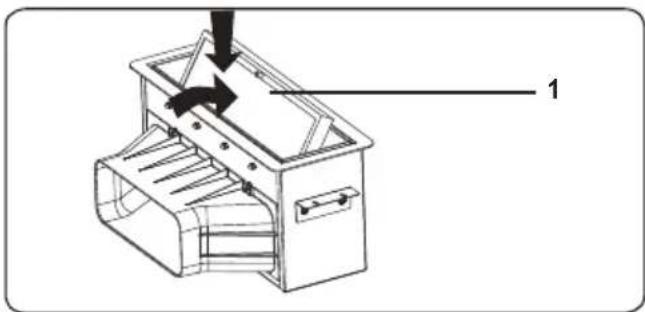
Cleaning the drip container
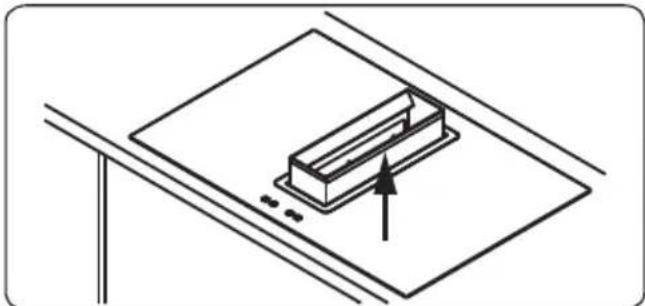
natural_image
Simple line drawing of a rectangular object placed on a flat surface with an arrow indicating direction (no text or symbols)- To collect water and food waste, the air extraction unit has a container a slot inside.
- Pull up the container inside the air extraction unit slot.
• After cleaning, insert the container.

The drip container can be cleaned in the dishwasher.
5.3 CLEANING OR REPLACING ACTIVATED CHARCOAL FILTER (RECIRCULATION ONLY)
- Activated charcoal filter housing
- Activated charcoal filter with frame
• Take out the activated carbon filter in the direction of the arrow towards the front. (is held with magnets).
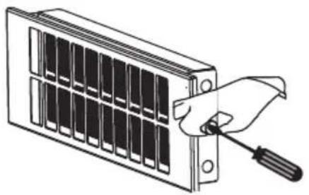
natural_image
Illustration of a hand using a screwdriver to adjust or install a grid-like device (no text or symbols visible)- Unscrew the connecting screw.

WARNING : Place the case on a firm surface, then push the filter down slightly to remove it.
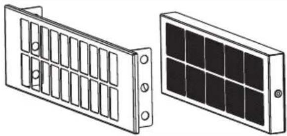
natural_image
Two technical illustrations of solar panel components: a front panel with grid-like slots and a back panel with grid-patterned panels (no text or symbols)- Remove the activated carbon filter from the filter frame as shown on.
- Allow the activated carbon filter to regenerate for one hour inside the baking oven at about 200°C. After cooling down, reinsert the filter into the hood.
• This procedure may be repeated not more than 10 times, after that filter must be replaced by a new one. - Re-insert the activated carbon filter by performing the previous steps in reverse order.
5.4 MAINTENANCE INTERVALS

The device performance will be negatively impacted by any non-compliance with the maintenance
intervals!
In case of overlong use, the metal grease filter as well as the activated charcoal filter will be clogged with fat and dirt particles, which will negatively impact the device performance.
- Please observe all maintenance intervals specified in this manual.
| Interval Maintenance task | |
| After assembling and in case of heavy contamination | Outside cleaning of the device. |
| After cleaning the extractor hood | Servicing the device. |
| Every other week or when the grease filter prompt appears | Cleaning the metal grease filter. |
| Every 3 month or in case of decreasing performance | Cleaning or replacing the activated carbon filter (for circula-tion fan operation only). |
6. TROUBLESHOOTING&TRANSPORT
6.1 TROUBLESHOOTING

If you still have a problem with your appliance after checking these basic troubleshooting steps, please contact an authorised service person or qualified technician.
| Problem Possible Cause Solution | ||
| Hob control card's display is blacked out. The hob or cooking zones cannot be switched on. | There is no power supply. | Check the household fuse for the appliance.Check whether there is a power cut by trying other electronic appliances. |
| The hob switches off while it is in use and an 'F' flashes on each display. | The controls are damp or an object is resting on them. | Dry the controls or remove the object. |
| The hob switches off while it is use. | One of the cooking zones has been on for too long. | You can use the cooking zone again by switching it back on. |
| The hob controls are not working and the child lock LED is on. | Child lock is active. Switch off the child lock. | |
| The saucepans make noise during cooking or your hob makes a clicking sound during cooking. | This is normal with induction hob cookware. This is caused by the transfer of energy from the hob to the cookware. | This is normal. There is no risk, neither to your hob nor to your cookware. |
| The 'U' symbol lights up in the display of one of the cooking zones. | There is no pan on the cooking zone, or the pan is unsuitable. | Use a suitable pan. |
| Power level 9 or 'P' is automatically reduced. If you select power level 'P' or 9 on two cooking zones, which are on the same side, at the same time. | Maximum power level for the two zones is reached | Operating both zones at power level 'P' or 9 would exceed the permitted maximum power level for the two zones. |
6.2 TRANSPORT
If you need to transport the product, use the original product packaging and carry it using its original case. Follow the transport signs on the packaging. Tape all independent parts to the product to prevent damaging the product during transport.
If you do not have the original packaging, prepare a carriage box so that the appliance, especially the external surfaces of the product, is protected against external threats.
Declaration of conformity
We declare that our products meet the applicable European Directives, Decisions and Regulations and the requirements listed in the standards referenced.
C€
Disposal of the device
natural_image
Symbol of a trash bin crossed with diagonal lines, representing waste sorting or disposal (no text or labels)Old devices cannot be placed in the household waste!
If the device can no longer be used, every consumer is legally obliged to hand in devices separately from household waste e.g. at a collection site of their local authority / borough. This ensures that the devices are properly recycled and negative effects on the environment are avoided.
Therefore, electrical devices are marked with the symbol depicted.
Recycling

natural_image
Recycling symbol composed of three chasing arrows forming a triangle (no text or labels)Our packaging is made of environmentally-friendly, recyclable materials:
External packaging made of cardboard
Moulded parts made of CFC-free polystyrene (PS)
Films and bags made of polyethylene (PE)
Wrapping straps made of polypropylene (PP).
If you have sufficient space to permit it, we recommend you retain the packaging, at least during the warranty period. If the device must be returned for repair or brought into a repair drop-off centre, the device is only adequately protected in the original packaging.
If you want to no longer retain the packaging, please dispose of this in an environmentally friendly manner.
- DAS KOCHFELD MIT ABZUGSHAUBE INSTALLIEREN
- Metall-Fettfilter
- ALGEMENE VEILIGHEIDSWAARSCHUWINGEN
- WAARSCHUWINGEN BIJ DE INSTALLATIE
- INSTALLATIE VAN DE KOOKPLAAT MET AFZUIGING
- WAARSCHUWING: DIT TOESTEL MOET WORDEN GEAARD.
- Metalen vetfilter
- PROBLEEMOPLOSSING EN TRANSPORT
- PROBLEEMOPLOSSING
- PIÈCES DU PRODUIT
- INSTALLATION DE LA TABLE DE CUISSON ASPIRANTE
- RACCORDEMENT ÉLECTRIQUE ET SÉCURITÉ
- DIMENSIONS D'INSTALLATION
- Thank you for choosing this product.
- CONTENTS
- SAFETY INSTRUCTIONS
- GENERAL SAFETY WARNINGS
- INSTALLATION WARNINGS
- DURING USE
- DURING CLEANING AND MAINTENANCE
- Disposal of your old machine
- INSTALLATION AND PREPARATION FOR USE
- INSTRUCTIONS FOR THE INSTALLER General instructions
- PRODUCT PARTS
- Induction hob
- ASSEMBLYING OF THE AIR EXTRACTION UNIT
- INSTALLATION OF THE VENTING HOB
- ELECTRICAL CONNECTION AND SAFETY
- WARNING: THE APPLIANCE MUST BE EARTHED.
- POWER SUPPLY CONNECTION
- INSTALLATION DIMENSIONS
- PRODUCT FEATURES
- List of Components
- USE OF PRODUCT
- HOB CONTROLS
- Induction Zone
- Cookware
- Touch Control Unit
- Switching the Hob On
- Switching the Hob Off
- Switching the Cooking Zones On
- Switching the Cooking Zones Off
- Switching all Cooking Zones Off
- Residual Heat Indicator
- Bridge Zone
- Switching the Bridge Zone On
- Switching the Bridge Zone Off
- Smart Pause
- Safety Switch-Off Function
- Child Lock
- Key Lock
- Timer Function
- Minute Minder Timer (1 - 99 min.)
- Cooking Zone Timer (1 - 99 min.)
- Buzzer
- Boost Function
- Switching the Air Extraction Unit On-Off
- Switching the Air Extraction Unit Fan Level On
- Switching the Air Extraction Unit Level Off
- Filter Cleaning Message
- CLEANING AND MAINTENANCE
- HOB CLEANING
- General Instructions
- Cleaning the Ceramic Glass
- Cleaning the Stainless Steel Parts (if available)
- CLEANING THE METAL GREASE FILTER
- Remove the metal grease filter
- Manual Cleaning
- After cleaning
- Inserting the metal grease filter
- Cleaning the drip container
- CLEANING OR REPLACING ACTIVATED CHARCOAL FILTER (RECIRCULATION ONLY)
- MAINTENANCE INTERVALS
- TROUBLESHOOTING&TRANSPORT
- TROUBLESHOOTING
- TRANSPORT
- C€
- Disposal of the device
- Recycling
Brand : VESTEL
Model : VEA36016
Category : Cooktop