GAWUXGFTG - Storage accessory Gladiator - Free user manual and instructions
Find the device manual for free GAWUXGFTG Gladiator in PDF.

User questions about GAWUXGFTG Gladiator
0 question about this device. Answer the ones you know or ask your own.
Ask a new question about this device
Download the instructions for your Storage accessory in PDF format for free! Find your manual GAWUXGFTG - Gladiator and take your electronic device back in hand. On this page are published all the documents necessary for the use of your device. GAWUXGFTG by Gladiator.
USER MANUAL GAWUXGFTG Gladiator
BALL, GOLF & CLEAN-UP CADDY INSTALLATION SAFETY....2
BALL, GOLF & CLEAN-UP CADDY INSTALLATION INSTRUCTIONS ....2
Mount the Ball Caddy to GearTrack® Channels or GearWall® Panels....3
Assemble Ball Caddy....3
Assemble Golf Caddy....4
Mount the Golf Caddy to the wall....4
Assemble Clean-up Caddy....6
Mount the Clean-up Caddy to the wall....6
Warranty....6
TABLE DES MATIÈRES
SÛRETÉ DES INSTALLATIONS DU CASIER À ACCESSOIRES POUR NETTOYAGE, DU CASIER DE GOLF ET DU PANIER POUR BALLONS ...8
SÛRETÉ DES INSTALLATIONS DU CASIER À ACCESSOIRES POUR NETTOYAGE, DU CASIER DE GOLF ET DU PANIER POUR BALLONS ...8
www.gladiatorgarageworks.com
www.gladiatorgarageworks.ca
BALL, GOLF AND CLEAN-UP CADDY INSTALLATION SAFETY
Your safety and the safety of others are very important.
We have provided many important safety messages in this manual and on your appliance. Always read and obey all safety messages.

This is the safety alert symbol.
This symbol alerts you to potential hazards that can kill or hurt you and others.
All safety messages will follow the safety alert symbol and either the word "DANGER" or "WARNING."
These words mean:
DANGER
You can be killed or seriously injured if you don't immediately follow instructions.
WARNING
You can be killed or seriously injured if you don't follow instructions.
All safety messages will tell you what the potential hazard is, tell you how to reduce the chance of injury, and tell you what can happen if the instructions are not followed.
BALL, GOLF AND CLEAN-UP CADDY INSTALLATION INSTRUCTIONS
| Parts Maximum Weight Limit Tools and Parts Required | ||
| Ball Caddy 25 lbs (11.3 kg) N/A | ||
| Golf Caddy | 25 lbs (11.3 kg) for the shoe shelf | ^3/8 " (9.52 mm) nut driver, ^1/2 " (1.27 cm) nut driver, Phillips- head screwdriver,Hex Key |
| 50 lbs (22.7 kg) for the golf bag shelf | ||
| 75 lbs (34.0 kg) for the golf bag caddy | ||
| Clean-Up Caddy 25 lbs (11.3kg) | ^3/8 " (9.52 mm) Nut driver, Phillips screwdriver | |
IMPORTANT : Intended to be installed on Gladiator® Garageworks GearWall® panels or GearTrack® channels.
NOTES :
- Be sure the Gladiator ^® GearWall ^® panel or GearTrack ^® channel is installed with mounting screws in every slot and at every stud location with a maximum of 24" (60.96 cm) horizontally between screws.
- Remove the caddies parts and fasteners, and dispose of/recycle all packaging materials.
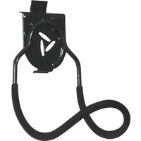
BALL CADDY
Mount the Ball Caddy to GearTrack® channel or GearWall® panel for Assembly
-
Align the mounting brackets, one on each side of the rear frame, with the desired slots in the GearWall® panel or GearTrack® channel.
-
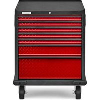
Engage the bracket rims into the slots in the GearWall ^® panel or GearTrack ^® channel by lifting up, pushing toward the wall and lowering the rims into the slots.
natural_image
Technical line drawing of a mechanical clamp or bracket assembly (no text or symbols)A. Mounting bracket
- Inspect the ball caddy from the side to ensure the bracket rims are fully engaged in the slots.
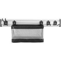
Assemble Ball Caddy
IMPORTANT: Before assembling, first mount the ball caddy to GearWall® panel or GearTrack® channel.
- Reach inside the ball caddy and unfasten the fabric closures running along the bottom front of the caddy.
natural_image
Technical line drawing of a mechanical assembly with labeled components A (no text or symbols present)A. Fabric closures
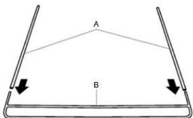
- Slide the hollow metal rods onto each end of the lower frame, as shown.
text_image
A BA. Hollow metal rod
B. Lower frame
- Holding the lower frame where it is joined with the metal rods, place the frame, bottom edge down, into the ball caddy at an angle.

text_image
A B CA. Upper frame
C. Lower frame
B. Ball caddy front
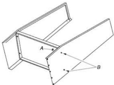
- Slide the hollow metal rods that are joined to the lower frame, onto each end of the upper frame, as shown.
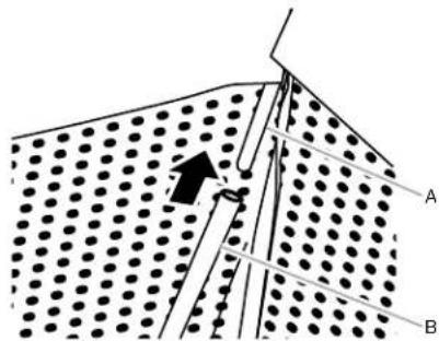
text_image
Diagram showing a mechanical or structural assembly with labeled parts A and B, featuring a dotted pattern and directional arrows.A. Upper frame
B. Ball caddy front
- Pull the lower frame forward until it is between the fabric closures at the bottom of the ball caddy. Fasten the fabric closures around both cross bars of the lower frame.
NOTE : Make sure the fabric closures are fastened tightly around both the upper and lower crossbars of the frame.
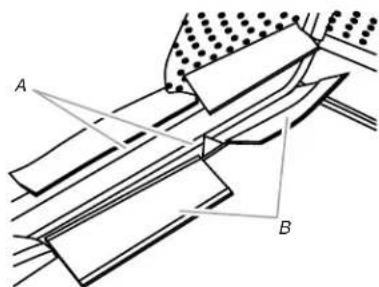
text_image
A BA. Crossbar
B. Fabric closures
- Attach the eight hooks, one on each end of the four elastic straps, onto the upper and lower frame, as shown.
text_image
Technical diagram of a heat exchanger or cooling unit with labeled components A and B, showing internal structure and cross-sectional views.A. Upper frame
B. Hook
GOLF CADDY
Assemble Golf Caddy
F1
F1: 516 " (7.93 mm) hex-head bolt (14)

F2
F2: 516 " (7.93 mm) flange nut (4)
- Using ^5/16 " (7.93 mm) hex-head bolts (F1) and ^5/16 " (7.93 mm) flange nuts (F2), attach the golf bag shelf to the sides as shown.
natural_image
Technical line drawing of a structural frame with labeled points A and B, showing internal components and alignment lines (no text or symbols beyond labels)A. 5/16" (7.93 mm) flange nut (F2)
B. ^5/_16 " (7.93 mm) hex-head bolt (F1)
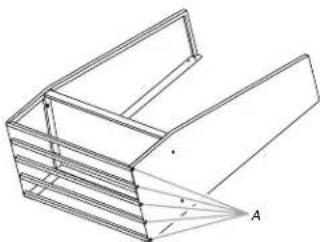
- Create a shoe shelf by using 516 " (7.93 mm) hex-head bolts (F1), to attach the 5 rods to both sides of the golf caddy, as shown.
natural_image
Technical line drawing of a 3D mechanical part with layered structure and labeled point A (no text or symbols beyond label)A. ^5/_16 " (7.93 mm) hex-head bolt (F1)
- Stand the golf caddy upright.
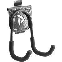
Attach Mounting Brackets

F7


F8 F10
F8 Washer (8) F10 Acorn nut (4)
F2 F3b
F2 5/16" (7.93 mm) flange nut (8) F3b Phillips-head screw (4) F7 Carriage-head bolt (8)
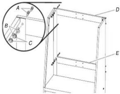
-
With the mounting bracket rims pointing down, align the 2 bracket holes with the top two holes in each side.
-
Working from the back, insert a carriage-head bolt (F7) through the holes in the bracket and into the side.
-
Working from the front, fasten each bolt with a washer (F8) and a flange nut (F2). Completely tighten the nuts.
-
Repeat steps 1 through 3 to attach the lower mounting bracket.
NOTE : Hand tighten the nuts attaching the lower bracket. In order to mount the golf caddy on the wall, this bracket will need to be adjusted.
text_image
Technical diagram of a mechanical assembly with labeled components A, B, C, D, and E, including an inset magnified view.A. Carriage-head bolts (F7)
D. Upper mounting bracket
B. Washer (F8)
E. Lower mounting bracket
C. Flange nuts (F2)
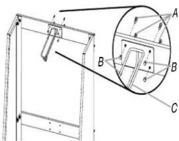
- Using Phillips-head screws (F3b) and acorn nuts (F10), attach the golf bag divider to the 4 holes in the center of the upper mounting bracket.
text_image
Technical diagram showing a mechanical assembly with labeled components A, B, and C, including an inset magnified view.A. Phillips-head screws (F3b)
C. Golf bag divider
B. Acorn nuts (F10)
Mount the Golf Caddy to the Wall
IMPORTANT: If Gladiator® GearTrack® channels will be used to mount the golf caddy, they must be installed 18" (46 cm) apart.
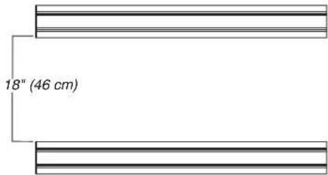
text_image
18" (46 cm)-
Determine caddy mounting location on GearWall ^® panel or GearTrack ^® channels.
-
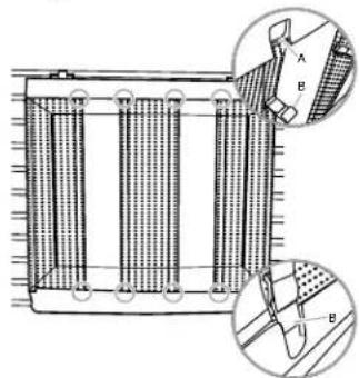
Engage the upper mounting bracket into the wall slots by lifting up, pushing toward the wall and lowering the bracket rims into the slots.
-
Inspect the golf caddy from the side to ensure the upper mounting bracket rims are fully engaged in the slots as shown.
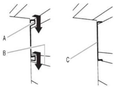
A. Bracket rim
B. Slot
C. Mounting bracket fully engaged
- Grasping the bolts, lift up on the lower mounting bracket to align the bracket rims with the slots on the GearWall® panel or GearTrack® channel.
- Push the golf caddy toward the wall and lower the lower bracket rims into the slots.
NOTE : Make sure the lower mounting bracket is fully engaged in the slots.
- Using a ^1/_2 " (1.27 cm) wrench, tighten the nuts on the lower mounting bracket.
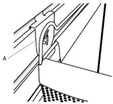
- Inspect the golf caddy from the sides to ensure both the upper and lower mounting brackets are fully engaged in their respective slots as shown.

natural_image
Diagram of a wall corner with two circular annotations and directional arrows indicating force or movement (no text or symbols present)- Attach each strap to the side panel and to the D-ring on the golf bag divider, as shown.
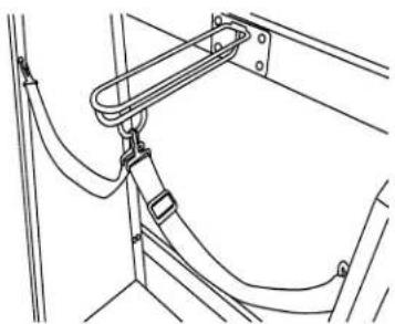
natural_image
Technical line drawing of a mechanical assembly with no visible text or symbolsCLEAN-UP CADDY
Assemble Clean-Up Caddy

F3b
F3b Phillips-head screw (2)

F10
F10 Acorn nut (6)
- Insert the threaded studs at the top of each side piece into the two holes in each side of the caddy back.
NOTE: Make sure the bracket rim on the caddy back is to the outside of the side pieces.
- Using two acorn nuts (F10) per side, attach the sides to the back. Completely tighten with a 38 " (9.52 mm) nut driver.
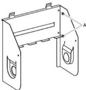
natural_image
Technical line drawing of a mechanical bracket with mounting holes and a triangular cutout labeled A (no text or symbols present)A. Acorn nuts (F10)
- Attach the caddy shelf (with the name badge facing up) by interlocking the shelf tabs with the tabs on the back.
NOTE : Make sure the lower mounting bracket is fully engaged in the slots.
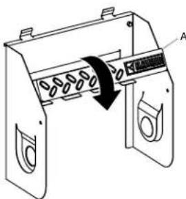
text_image
Technical diagram of a door handle mechanism with labeled component A and directional arrow indicating rotation or movement.A. Bottom piece
- Using the two Phillips-head screws (F3b) and two acorn nuts (F10) fasten the caddy shelf to the sides.
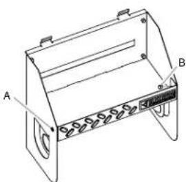
natural_image
Technical line drawing of a mechanical device with labeled points A and B (no text or symbols beyond labels)A. Phillips-head screw (F3b)
B. Acorn nut (F10)
- Holding each screw in place with a screwdriver, completely tighten the acorn nut with the nut driver.
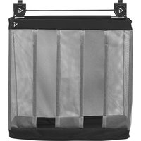
Mount the Clean-Up Caddy to the Wall
-
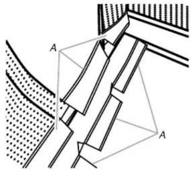
Engage the bracket rims located on the back of the caddy into the slots in the GearWall® panel or GearTrack® channel by lifting up, pushing toward the wall and lowering the rims into the slots.
-
Inspect the caddy from the side to ensure the bracket rims are fully engaged in the slots as shown.
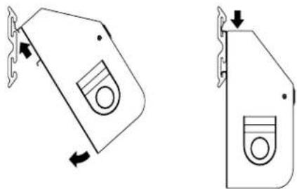
natural_image
Two technical line drawings of a mechanical component with directional arrows indicating movement (no text or symbols)WARRANTY
For warranty information:
In U.S.A. call 1-866-342-4089 or visit our website at
www.GladiatorGW.com
In Canada call 1-800-807-6777 or visit our website at www.gladiatorgarageworks.ca
There are many benefits for registering the product. Find out more and register the product online at www.gladiatorgarageworks.com.
NOTES
SÛRETÉ DES INSTALLATIONS DU CASIER À ACCESSOIRES POUR NETTOYAGE, DU CASIER DE GOLF ET DU PANIER POUR BALLONS
natural_image
Technical line drawing of a mechanical clamp or bracket assembly (no text or symbols)A. Bride de montage
natural_image
Technical diagram of a mechanical or architectural component with labeled points A, showing internal structure and alignment lines (no text or symbols beyond labels)text_image
Diagram showing a mechanical or structural assembly with labeled parts A and B, featuring a dotted pattern and directional arrows.natural_image
Technical diagram of a heat exchanger or cooling unit with internal cooling fins and a magnified inset showing cross-section view (no text or labels)natural_image
Technical line drawing of a structural component with labeled points A and B (no text or symbols beyond labels)natural_image
Isometric line drawing of a folded paper or metal frame structure with labeled point A (no text or symbols beyond label)text_image
Technical diagram of a mechanical assembly with labeled components A, B, C, D, and E, including an inset magnified view.A. Boulon de carrosserie (F7)
text_image
Technical diagram showing a mechanical assembly with labeled components A, B, and C, including an inset circular detail view.text_image
18" (46 cm)natural_image
Simple line drawing of a wall corner with two circular annotations and an arrow indicating direction (no text or symbols)natural_image
Technical line drawing of a mechanical assembly with no visible text or symbolsCASIER À ACCESSOIRES POUR NETTOYAGE
natural_image
Technical line drawing of a mechanical bracket with mounting holes and a triangular cutout labeled A (no text or symbols present)A. Écrous borgnes (F10)
text_image
Technical diagram of a device with labeled component A and directional arrow indicating rotation or movementA. Pièce inférieure
natural_image
Technical line drawing of a mechanical housing or enclosure with labeled points A and B (no text or symbols on the diagram itself)natural_image
Technical line drawing of two mechanical components with directional arrows indicating movement (no text or symbols)GARANTIE
www.gladiatorgarageworks.ca
natural_image
Technical line drawing of a mechanical clamp or bracket assembly (no text or symbols)natural_image
Technical diagram of a mechanical assembly with labeled components A, showing no readable text or symbols.A. Cierres de tela
text_image
Diagram showing a mechanical or structural assembly with labeled parts A and B, featuring a dotted pattern and directional arrows.A. Marco superior
B. Frente del contenedor para pelotas
natural_image
Technical diagram of a heat exchanger or cooling unit with internal cooling fins and labeled components (A, B, D), no readable text or symbols present.A. Marco superior
B. Gancho
natural_image
Technical line drawing of a structural component with labeled points A and B (no text or symbols beyond labels)A. Tuerca de brida de ^5 / _16 " (7,93 mm) (F2)
B. Perno de cabeza hexagonal de 516 " (7,93 mm) (F1)
natural_image
Isometric line drawing of a folded metal frame with labeled point A (no text or symbols beyond label)A. Perno de cabeza hexagonal de 516 " (7,93 mm) (F1)
text_image
Technical diagram of a mechanical assembly with labeled components A, B, C, D, and E, including an inset magnified view.text_image
Technical diagram showing mechanical assembly with labeled components A, B, and C, including a magnified inset view.A. Tornillos Phillips (F3b)
B. Tuercas ciegas (F10)
C. Divisor para bolsas de golf
text_image
18" (46 cm)natural_image
Diagram of a wall corner with two circular arrows pointing to specific points (no text or symbols present)natural_image
Technical line drawing of a mechanical assembly with no visible text or symbolsnatural_image
Technical line drawing of a mechanical bracket or housing component with mounting holes and a triangular cutout labeled A (no text or symbols present)text_image
Technical diagram of a device with labeled component A and directional arrow indicating rotation or movementA. Pieza inferior
natural_image
Technical line drawing of a mechanical housing or enclosure with labeled points A and B (no text or symbols beyond labels)A. Tornillo Phillips (F3b)
B. Tuerca ciega (F10)
natural_image
Technical line drawing of two mechanical components with directional arrows indicating movement (no text or symbols)GARANTÍA
©/TM ©2017 Gladiator Used under license in Canada. All rights reserved.