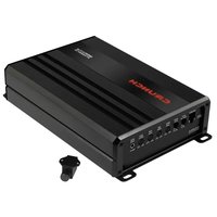
Gravity GTX2250.1D - Receiver Crunch - Free user manual and instructions
Find the device manual for free Gravity GTX2250.1D Crunch in PDF.


User questions about Gravity GTX2250.1D Crunch
0 question about this device. Answer the ones you know or ask your own.
Ask a new question about this device
Download the instructions for your Receiver in PDF format for free! Find your manual Gravity GTX2250.1D - Crunch and take your electronic device back in hand. On this page are published all the documents necessary for the use of your device. Gravity GTX2250.1D by Crunch.
USER MANUAL Gravity GTX2250.1D Crunch
natural_image
Simple cloud icon with diagonal lines crossing over a cloud shape (no text or symbols)
natural_image
Simple black-and-white diagram of a sun with radiating lines and central cross (no text or symbols)
ACHTUNG
Technical changes and errors reserved
* Prevents error messages in the vehicle diagnostic system

text_image
12V
10 \~ 90% -25 \~ 50°C

natural_image
Simple cloud icon with diagonal lines crossing over a circle, no text or symbols present
natural_image
Simple black-and-white diagram of a sun with radiating lines and central cross (no text or symbols)
CAUTION
Please read these operating instructions completely before starting the installation and putting the device into operation.
INTENDED USE
This product is designed to operate in a vehicle with an on-board voltage of +12 V with negative ground. The device functions as an audio amplifier that is used within a vehicle sound system. If you have any questions about product safety, please contact: amplifiers@audiodesign.de
DISPOSAL/RECYCLING
If you have to dispose the device and its components, please note that no electronic devices must be disposed in the household waste. Dispose of the device and its components at a suitable recycling facility in accordance with local waste regulations. If necessary, consult your local authority or dealer.
More information at www.audiodesign.de/english/disposal
SCOPE OF DELIVERY
1 x Mono amplifier
1 x Bass level remote controller including connection cable
1 x Cable harness with 4-pin plug (high level inputs with EPS)
1 x Cable harness with 4-pin plug (low level inputs with RCA jacks)
1 x Fuse (external)
1 x Owner's manual
IMPORTANT NOTES PRIOR TO INSTALLATION
- Attach the device to a suitable mounting location in the vehicle by using screws. Make sure that the device cannot vibrate while driving and that it is screwed tightly.
- During installation, make sure that no parts that are standard in the vehicle, such as cables, on-board computers, seat belts, tank or similar parts, are damaged or removed.
- Make sure that the device receives sufficient cooling at the installation location. Do not mount the device in closed housings that are too small without air circulation or near heat-radiating parts or electronic controls of the vehicle.
- All cables should be kept as short as possible to avoid losses and interference.
- Protect the device from moisture, dust and dirt.
- Make sure that the input/output cables are far enough away from the power supply cables, otherwise interference may occur.
- The performance and reliability of the sound system depends on the quality of the installation. It is best to have the installation carried out by an installation specialist.

CAUTION
Before you start with the installation, disconnect the ground (−) terminal of the vehicle battery to avoid short circuits and damage.
POWER SUPPLY AND TURN-ON-CONNECTION
To connect the power supply, only use power cables that are sufficiently dimensioned (See page 43, fig. 6). The cross-section of the cables must be the same size for +12V and ground.
First establish a connection between the GND terminal of the amplifier and a suitable ground point on the vehicle body (Fig. 2.3). To guarantee a good connection, remove any dirt or rust from the ground point.
Then connect the +12V terminal of the amplifier to the positive terminal of the vehicle battery (Fig. 2.1). The enclosed fuse with fuse holder must be installed in this positive power cable (Fig. 2.4). For safety reasons, the cable length from the +12V connection to the fuse must be less than 30 cm.
In addition, the positive power cable must be protected with another fuse near the battery (Fig. 2.5). This fuse is not included in the scope of delivery and should have the same fuse value as the enclosed fuse. For safety reasons, the cable length from the positive terminal of the battery to the fuse must be less than 30 cm.
Then connect the turn-on-wire from the car radio with the amplifier's REM terminal (Fig. 2.2). A cable with a cross-section of 0.5mm^2 is adequate.
LOUDSPEAKER CONNECTION
- The total impedance must not be lower than 1 .
CAUTION: If the amplifier is operated with speaker impedances that are too low, it could be overloaded and thus permanently damaged.
LOW LEVEL INPUTS
The low level inputs on LINE INPUT (Fig. 1.2) are suitable for connecting RCA cables if your car radio owns RCA preamplifier outputs. Then connect the RCA sockets of the included low level cable connector to the RCA cables from the head unit (car radio). To activate the low level inputs, press the INPUT LEVEL button (Fig. 1.4) to LOW.
HIGH LEVEL INPUTS
The high level inputs on LINE INPUT (Fig. 4.1) are suitable for connecting speaker cables if your car radio does not have RCA preamplifier outputs. To do this, extend the corresponding speaker cables of the car radio with high-quality speaker cables to the installation location of the amplifier. Then connect the appropriate speaker cables to the open cable ends of the included high level cable connector. To activate the high level inputs, press the INPUT LEVEL button (Fig. 4.2) to HIGH.
AUTO TURN-ON
If there is no turn-on cable from the car radio available, you must use the automatic turn-on function. To do this, press the button AUTO TURN-ON (Fig. 5.3) to ON. The connection for the REM turn-on cable (Fig. 2.2) does not need to be occupied in this case.
CAUTION: The automatic turn-on function only works in conjunction with the high level inputs on LINE LEVEL INPUT (Fig. 5.1). This function may not be able to be used with older car radios.
INPUT SENSITIVITY
Turn the INPUT GAIN controller (Fig. 1.5) counterclockwise to the MIN position. Then turn the volume control on the car radio to 80% – 90% of the maximum volume. Now slowly turn the INPUT GAIN controller (Fig. 1.5) clockwise until you hear slight distortion from the speakers. Then turn back the INPUT GAIN controller (Fig. 1.5) a little until you can no longer hear any distortion.
SUBSONIC FILTER
With the SUB SONIC controller (Fig. 1.6) you can adjust the lower crossover frequency, to filter the very low frequencies to relieve the subwoofer or to generate a bandpass signal. If you don't want to use this function, turn the controller (Fig. 1.6) to the very left to the 10 Hz position.
ATTENTION: If the controller SUB SONIC (Fig. 1.6) is set higher than the controller LOW PASS (Fig. 1.7), no audio signal is heard.
LOWPASS FILTER
Set the desired crossover frequency by using the controller LOW PASS (Fig. 1,7). Thus to that only the frequencies below the chosen crossover frequency will be amplified and the subwoofer plays more precisely and efficient.
BASS BOOST
Use the BASS BOOST controller (Fig. 1.9) to adjust the bass boost between 0 – 12 dB. Use this controller carefully and avoid distorted playback.
BASS LEVEL REMOTE
With the included remote, the bass level can be adjusted e.g. from the driver's seat. Connect the remote at the BASS LEVEL REMOTE terminal (Fig. 1.9) with the included cable.
STATUS LED
The POWER/PROTECT LED (Fig. 1.1) lights up green, when the amplifier is in operation.
The POWER/PROTECT LED (Fig. 1.1) lights up red, when the device is overheated or an error has occurred. After cooling down, the device should work again. If the error persists, please note the information in the section TROUBLESHOOTING.
FIGURES (P. 40-42)
CONNECTIONS AND CONTROLLERS (FIG. 1)
(1) Status LED
(2) Audio signal inputs
(3) Push button for the automatic turn-on function
(4) Push button for input type (high level / low level)
(5) Rotary controller for input sensitivity
(6) Rotary controller for subsonic filter
(7) Rotary controller for low pass filter
(8) Rotary controller for bass boost
(9) Terminal for the included bass level remote
POWER SUPPLY AND TURN-ON CONNECTION (FIG. 2)
(1) +12 V terminal for the positive connection from the vehicle battery
(2) REM terminal for the turn-on signal from the car radio
(3) GND terminal for the ground connection
(4) External cable fuse for amplifier (included in the scope of delivery)
(5) External cable fuse for +12V power wire (not included in the scope of delivery)
MONO OPERATION (FIG. 3)
(1) Audio signal L/SUB from the car radio
(2) Audio signal R/SUB from the car radio
(3) Bass level remote
(4) Subwoofer L+/R-
HIGH LEVEL INPUTS (FIG. 4)
Please note the information on page 42.
POWER SUPPLY CABLES (FIG. 5)
Please note the recommendations on page 42 for the cable length and the cable cross-section of the power cables in order to ensure an adequate and safe power supply for the amplifier.
TROUBLESHOOTING
First check the fuse of the installed power cable on the vehicle battery
The fuse is defective?
Replace the defective fuse with one of equal value, but never with a higher value.
- The fuse fails again.
In this case there appears to be a short circuit between the fuse and the device. To do this, check the entire length of the +12V power cable from the battery to the device for damage and whether there is a short circuit to ground, e.g. a contact with the vehicle chassis or body. If necessary, replace the defective power cable.
The fuse is apparently okay?
Use a standard 12 volt voltmeter to check the voltage between the +12V connection and the ground connection on the device.
- There is no voltage.
Use the voltmeter to check the fuse located near the vehicle battery to see if there is voltage between the output and ground.
If there is no voltage there, either the fuse holder or the fuse is defective, even though it appears to be okay. If necessary, replace the fuse holder or fuse.
- There is voltage.
If you operate the device with a turn-on cable (REM) from the car radio to the REM connection of the device, the AUTO TURN-ON switch must be in OFF position.
A turn-on cable (REM) is connected to the REM connection of the device.
Use the voltmeter to check whether there is voltage between the device's REM terminal and ground. The car radio must be switched on.
There is no voltage.
- Check the turn-on cable from the device to the car radio for a short circuit or damage. If necessary, replace the turn-on cable.
There is voltage.
- The device is probably malfunctioning or defective. Contact your specialist dealer.
If you operate the device with the speaker signals (high level mode), the AUTO TURN-ON switch must be switched to ON.
• The AUTO TURN-ON switch is in the ON position, but the device remains off.
Check the speaker cables from the car radio to the device for short circuits or damage. If necessary, replace the speaker wires or insulate the damaged area.
PROTECT LED IS ON
Check the following steps:
Short circuit on the speaker cables
First disconnect all speaker cables from the amplifier. Use a multimeter to check the ohmic impedance of each loudspeaker by measuring between its plus and minus lines. With standard loudspeakers the value fluctuates between 3 and 5 ohms. The values for low-resistance subwoofers can be lower.
• The measurement shows a resistance value of less than 0.5 Ohms
Then there is a short circuit. Remove the cables of the affected loudspeaker at its connections. Now use the multimeter to check the ohmic impedance directly at the loudspeaker connections by measuring between the plus and minus connections.
The measurement shows a resistance value of more than 0.5 Ohms
- The speaker is fine, so the speaker cables appears to be defective and causing a short circuit. Replace the defective speaker cable.
The measurement shows a resistance value of less than 0.5 Ohms
- The speaker appears to be defective and causes an short circuit. Replace the defective speaker.
The load impedance of the loudspeakers or the subwoofer is too low
Compare the ohmic impedance of the connected loudspeaker or subwoofer with the technical specifications of the amplifier. For example, if the amplifier is only designed for 2 or 4 ohm operation, no loudspeaker with less than 2 ohms may be connected.
The cross-section of the power cables is too small
If the cable cross-section is too small, this leads to an increased ohmic resistance and thus to a voltage drop (voltage loss). This indicates that the amplifier consumes more power. The increased power consumption results in a significantly higher heat development and the amplifier switches to thermal protection mode. If necessary, lay power cables with a larger cable cross-section.
The amplifier is overheated
Every amplifier requires sufficient air circulation to be able to dissipate the heat generated during operation. If necessary, change the installation position in favor of better cooling of the amplifier or ensure better air circulation at the installation location.
Turn off the sound system and wait about half an hour for the amplifier to cool down again. With very hot outside temperatures and strong sunlight, enormous heat develops inside the vehicle. The amplifier then activates its thermal protection circuit to prevent damage. After cooling down, the amplifier works properly again.
TROUBLESHOOTING
| NO SOUND / POWER LED IS ON |
| Check the following steps: |
| Low level mode: Are the RCA cables on the car radio and the device connected correctly?The RCA cables are connected correctly.An RCA cable could be defective. Check the function of the RCA cables on another audio device. If necessary, replace the defective RCA cable. |
| High level mode: Are the speaker cables connected correctly to the car radio and the device's high level inputs or to the high level cable connector?The speaker cables are connected correctly.A speaker cable could be defective. If necessary, replace the speaker cable or insulate the damaged area. |
| Are the speaker cables between the speakers or subwoofer connected correctly to the speaker outputs on the device?The speaker cables are connected correctly.A speaker cable could be defective. If necessary, replace the speaker cable or insulate the damaged area. |
| Is the respective high-pass filter or subsonic filter on the device set higher than the low-pass filter?Then slowly turn down the high pass filter or subsonic filter control until you hear the sound. |
| Are the speakers or subwoofer working?Hold a standard 9 volt block battery to the connections of the speaker or subwoofer.A faint cracking noise can be heard.Speaker or subwoofer is fine.Nothing can be heard.Speaker or subwoofer could be defective. If necessary, replace the defective component. |
| Are the settings on the car radio set correctly?Check the fader and balance settingsCheck whether mute is enabledCheck whether a high-pass or low-pass filter is activatedCheck whether playback is pausedCheck source signal settingsCheck whether any subwoofer output is activated |
| AUDIBLE NOISES (ENGINE SPEED-DEPENDENT) |
| Check the following steps: |
| Have the RCA cables been laid separately from the power cable in the vehicle?If necessary, re-route the cables and make sure that the RCA cables are laid separately from the power cable on the left and right of the vehicle. |
| Is the ground connection of the device connected correctly?Make sure that the ground connection of the device is not connected directly to the negative terminal of the vehicle battery. Select a suitable ground point on the vehicle body to connect. If necessary, use contact spray to improve the conductivity of the connections. |
| Is the conductivity of the vehicle battery ground cable to the body okay?Make sure that the ground connection of the vehicle battery has a stable and conductive connection to the body. If necessary, use contact spray to improve the conductivity of the connections. |
| AUDIBLE DISTORTION OR HISSING NOISES |
| Check the following steps: |
| Is the input level controller on the device set too high?Slowly turn the controller down until you hear a clean audio signal. |
| Is the bass boost on the device set too high?Slowly turn the controller down until you hear a clean audio signal. |
| Is the loudness function on the car radio set too high?Disable loudness or turn down the loudness setting until you hear a clean audio signal. |
| Are the EQ and sound settings on the car radio set too high?Turn down the treble, mid and bass settings or turn off the equalizer until you hear a clean audio signal. |
CARACTÉRISTIQUES
natural_image
Simple cloud icon with diagonal lines crossing over a circle, no text or symbols present
natural_image
Simple black-and-white diagram of a sun with radiating lines and central cross (no text or symbols)
PRÉCAUTION
natural_image
Simple black-and-white icon showing a cloud with raindrops crossed by a diagonal line (no text or symbols)
natural_image
Simple black-and-white diagram of a sun with radiating lines and central cross (no text or symbols)
ATTENZIONE
natural_image
Simple black-and-white icon of a cloud with raindrops crossed by two crossed lines (no text or symbols)
natural_image
Simple black-and-white diagram of a sun with radiating lines and central cross (no text or symbols)
PRECAUCIÓN
www.audiodesign.de – www.crunchaudio.de
© Audio Design GmbH, All Rights Reserved