FWM04DATV3 - Air Conditioning DAIKIN - Free user manual and instructions
Find the device manual for free FWM04DATV3 DAIKIN in PDF.

User questions about FWM04DATV3 DAIKIN
0 question about this device. Answer the ones you know or ask your own.
Ask a new question about this device
Download the instructions for your Air Conditioning in PDF format for free! Find your manual FWM04DATV3 - DAIKIN and take your electronic device back in hand. On this page are published all the documents necessary for the use of your device. FWM04DATV3 by DAIKIN.
USER MANUAL FWM04DATV3 DAIKIN
text_image
17.0° 37.0°
flowchart
graph LR
    A["Set - ZN/2"] --> B["Set + ZN/2"]
    B --> C["Heat Source Symbol"]
Dove:
line
| Condition | Value | |---|---| | set-3°C | 3 | | set-2°C | 2 | | set-0.5°C | 1 | | set | |FUNZIONAMENTO AUTOMATICO PER TERMINALE IDRONICO A 4 VELOCITA' E VALVOLA/E ON/OFF (O ASSENTE/I):
line
| Temperature Level | Value | | :--- | :--- | | set-3°C | 3 | | set-2°C | 2 | | set-1°C | 1 | | set-0.5°C | sm | | set | * (indicated by asterisk) |FUNZIONAMENTO AUTOMATICO PER TERMINALE IDRONICO A 3 VELOCITA' E VALVOLA/E MODULANTE/I
other
| Level | Value | |---|---| | set-3.5°C | 3 | | set-3°C | 2 | | set-2.5°C | 1 | | set-2°C | sm | | set-1.5°C | | | set | |line
| Condition | Value [%] | |---|---| | set | 20 | | set+0.5°C | 20 | | set+3°C | MAX |RISCALDAMENTO CON CONFIGURAZIONI A 3 VELOCITÀ
line
| Temperature | Value (%) | | :--- | :--- | | set-3°C | MAX | | set-0.5°C | 20 | | set | 100 |RISCALDAMENTO CON CONFIGURAZIONI A 4 VELOCITÀ
line
| Temperature | Value (%) | | :--- | :--- | | set-3.5°C | MAX | | set-2°C | 20 | | set-1.5°C | 20 | | set | MAX |text_image
17.0° 22.0°RISCALDAMENTO
text_image
× 30.0° 37.0°text_image
On set-0,5° set OffVALVOLA MODULANTE
line
| Condition | Value (%) | |---|---| | set | 100 | | set-1.5°C | 100 | | set-0.5°C | 20 | | set | 20 |CONSENSO VALVOLA DA SONDA ACQUA
text_image
× 25.0° 30.0°text_image
On set-0,5° set Off
text_image
37.0° 39.0°text_image
On 9° 10.0° Offtext_image
Vmin Set+0.5° Set+1.5° Vmedtext_image
Inib. Set-2.0° Set-1.5°CONSENSO DEUMIDIFICA DA SONDA ACQUA
text_image
✓ 10.0° ×COIL STATUS (DIGITALI DI LETTURA/SCRITTURA)
natural_image
Diagram of a rope knot with two connectors (no text or symbols)FWV, FWL, FWM, FWZ, FWR, FWS, FWD
CHANGING TEMPERATURE AND FAN SPEED SETS ....4
CHANGING OPERATING MODE ....5
TURNING THE ECONOMY FUNCTION ON/OFF ....5
ENABLING/DISABLING ELECTRIC HEATER OPERATION....5
ENABLING/DISABLING MINIMUM ROOM TEMPERATURE CONTROL....5
ENABLING/DISABLING ROOM HUMIDITY CONTROL ....5
CHANGING THE HUMIDITY SET......5
VIEWING THE WATER TEMPERATURE....6
LOCKING/UNLOCKING THE KEYBOARD 6
VIEWING TIME AND DATE 6
CHANGING CLOCK DATA....6
CONFIGURING TIME SLOTS....6
PARAMETERS MENU AND LISTS 7
ADJUSTMENT MENU....9
SETUP MENU 9
ADJUSTMENT LOGIC.... 10
SWITCHING BETWEEN COOLING/HEATING 10
VENTILATION....10
VALVE....13
ELECTRIC HEATER....14
ECONOMY 14
MINIMUM TEMPERATURE CONTROL ....14
DEHUMIDIFICATION ....15


NETWORKS AND CONNECTIVITY 16
CONNECTION TO SUPERVISION SYSTEM (EXTERNAL SUPERVISOR SYSTEM SOLUTION)....16
"SMALL" NETWORK SOLUTION....18
MIXED NETWORK....19
MEANINGS OF LEDS 20
TECHNICAL DATA 20
INSTALLATION AND MAINTENANCE....20
PROBE INSTALLATION....20
REMOTE AIR PROBE INSTALLATION....20
HUMIDITY PROBE INSTALLATION ....21
WATER PROBE INSTALLATION 21
USER UNIT INSTALLATION....22
ON-BOARD I/O BOARD INSTALLATION 23
ELECTRICAL CONNECTIONS....23
MAINTENANCE 23
I/O TABLE FOR THE BOARD....24
ELECTRICAL DIAGRAM....24

WARNING

KEEP THE DATA CABLES SEPARATE FROM THE POWER CABLES

SAFETY SYMBOLS

READ CAREFULLY

WARNING

DANGER VOLTAGE
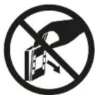
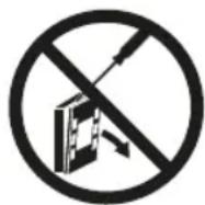
DO NOT PULL
DO NOT FORCE
GENERAL WARNINGS
Keep this manual intact and in good condition for the entire service life of the machine.

Read all of the information contained herein carefully, with particular attention to the parts marked with "Important" and "Attention"; failure to observe the instructions could cause damage to people or the machine.
In case of malfunction consult this manual and, if necessary, contact your nearest Daikin Europe NV assistance centre.
Installation and maintenance operations must be performed by qualified staff, unless stated otherwise in this manual.
Before performing any procedure on the unit, disconnect the voltage to the machine.
Failure to observe the regulations reported in the manual will cause the warranty to lapse immediately.
Daikin Europe NV will not be held liable for any damage deriving from improper use of the machine or failure to observe the regulations reported in this manual and onboard the unit.

This appliance is not intended to be used by children or persons with physical, sensorial or mental problems, inexpert or unprepared, without supervision.
Be careful that children do not approach the appliance.
Upon reception of the appliance check its conditions, verifying that it has there is no damage due to transport.
For the installation and news of any accessories please refer to the related technical data sheets.
GENERAL FEATURES
The FWECSA controller is designed to control all of the system units in the Daikin range with multi-speed, single-phase motor or coupled to an inverter for speed modulation.
The FWECSA controller system is composed of:
- I/O board containing the power supply circuit, the microprocessor system and the connectors (unscreewable) to connect the input and output devices;
- User unit composed of graphic display and keyboard (six keys) equipped with clock and probe to read the room temperature.

The connection between the I/O board and the user unit is set up using the relative connectors and a data transmission cable fitted with a pair of twisted conductors and shielding.
The controller makes serial communication possible on two types of networks:
- External Supervisor System solution: connection to an external supervision system with MODBUS RTU protocol on serial RS485;
- SMALL solution: connection of multiple FWECSA controllers in two possible configurations:
- MASTER/SLAVE on serial RS485
- MASTER/SLAVE on CW (Conveyed Waves), which can also be set up with External Supervisor System solutions.
- Mixed net solution: connection of multiple FWECSA controllers on different levels :
- MASTER/SLAVE on serial RS485 (external supervisor system or FWECSA), directions to the slaves RS485 (called zone MASTER)
- zone MASTER FWECSA, receiving directions from NET MASTER RS485, transmitting directions to SLAVES OC
- NET SLAVES OC, working exactly to the ZONE MASTER
MAIN FUNCTIONS
- Automatic or manual fan speed variation (selected from the keyboard);
- Management of ON/OFF or modulating valves for two or four-piped systems.
- SUPPORTING electric heater control, used during heating;
- SUMMER/WINTER mode switch (= cooling/heating) in four possible ways:
- manually, from the keyboard;
- manually, remotely (from digital input);
- automatically, depending on water temperature;
- automatically, depending on air temperature.
• dehumidification function control;
• operation with TIME SLOTS.
It is also supplied with:
- External pre-consensus digital input (for example: window contact, remote ON/OFF, presence sensor, etc.) that can enable or disable unit operation (contact logic: see board configuration parameters);
- Digital switching input Remote centralised Cooling/Heating (contact logic: see board configuration parameters);
- Digital input to enable ECONOMY function from remote control (contact logic: see board configuration parameters);
- Water temperature probe (accessory), one or two (optional with 4-pipe systems);
- STANDARD room air temperature probe (installed inside the user unit);
- Remote room air probe (accessory) that can be used, if connected, in place of the standard one installed in the user interface;
• Remote relative room air humidity probe (accessory);
• A completely configurable digital output (dry contact).
USER UNIT
text_image
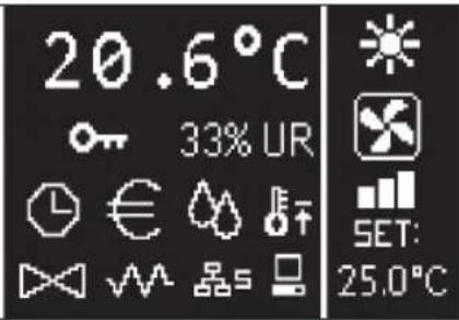
20.6°C 33% UR SET: 25.0°CThe main screen is divided into two parts (which are referred to below as lt side and rt side) by a vertical line that separates them.
the following information is contained on the lt side (from top to bottom and lt to rt):
- room temperature (read by the remote probe on-board the user unit, or by the probe connected to the I/O board terminal board, according to the configuration)
- ambient humidity (if there is a humidity probe installed and configured)
- status symbols:

time slots on

economy function on

dehumidification running

minimum room temperature function enabled

valve/s open

electric heater enabled/on

SMALL network on RS485 on

serial communication with supervision system

locked keyboard
- alarm signal: symbol and identification of the type of alarm overwrite the area normally dedicated to status symbols.
The following information is contained in the rt side (from top to bottom)
• identification of the operating mode

COOLING mode

HEATING mode
• identification of the ventilation status
• identification of the room air temperature SET value
If the unit is OFF the side will be completely covered by the word OFF written vertically across it.
KEYBOARD
There are 6 keys on the display screen; below are the basic functions associated with each key.

ON/OFF KEY
- switch the unit on/off
- go back to main screen

PRG KEY
- access to the MENU

MODE KEY
- change operating mode (HEATING/COOLING)

UP ARROW KEY
• change ventilation values/speed
• scroll through screens

SET KEY
• change SET/VENTILATION mode
• confirm value/return in screen scroll mode

DOWN ARROW KEY
• change ventilation values/speed
- scroll through screens
KEY COMBINATIONS

enable/disable TIME SLOTS

WATER temperature display (if the probe is installed)

clock DATA display (date and time)

LOCK/UNLOCK keyboard
TURN UNIT ON/OFF
To turn the unit on and off, it is necessary to go to the main screen and press the ON/OFF key from there. To go back to the main screen quickly from any point press the ON/OFF key and then press it again to turn the unit on/off.
The key has no effect if time slot operation is on (the clock symbol appears on the main screen). To turn the time slots on/off, see the relative paragraph.
CHANGE THE TEMPERATURE SET
To change the temperature SET it is necessary to view the main screen with the unit on, then proceed as follows;
- press the SET key once to highlight the (on the bottom rt of the screen) value of the entered room air temperature set;
- press the UP/DOWN arrow to change the value of the entered room air temperature set;
- press the SET key again to confirm the displayed value and exit temperature set edit mode.
CHANGE VENTILATION SPEED
- With the unit in operation, press the SET key twice to enter ventilation speed change mode (auto, extra-low speed, low, medium, high)
- press the UP/DOWN keys to change the ventilation speed;

MANUAL ventilation

AUTOMATIC ventilation

FORCED ventilation (not editable)
• with step ventilation, follow the editing sequence below:
| 3-speed hydronic unit | |||
| Low Medium High Automatic | |||
| 4-speed hydronic unit | ||||
| Extra-low | Low Medium | High Automatic | ||
- with modulating ventilation, the ventilation speed will appear as a percentage instead of steps. Pressing the arrows will change this value from the minimum set limit to the maximum limit (see ADJUSTMENT MENU); automatic ventilation mode is automatically applied outside of the limits;
- if the difference between the detected room air temperature and the entered set is within 0.5°C, ventilation will switch off and the word STDBY will appear;
- press the key SET is used to confirm/exit editing mode and go back to the main screen;
- if the controller is equipped with a water probe and the detected temperature is not high enough to enable ventilation, the controller will switch off and the symbol for the operating mode will flash:

COOLING mode

HEATING mode
CHANGING OPERATING MODE
To change the operating mode (Cooling/Heating) press the MODE key from the main screen.
TURNING THE ECONOMY FUNCTION ON/OFF
To turn the ECONOMY function on it is necessary to view the main screen. From here:
- press the UP/DOWN keys to scroll through the screens until you get to the “Turning the economy function On” mask;
• press the SET key to enter edit mode; - press the UP/DOWN keys to turn the function on/off and press the SET key again to confirm;
- press the ON/OFF key to go back to the main screen.
If the function is on, the economy symbol will appear in the main screen.
ENABLING/DISABLING ELECTRIC HEATER OPERATION
To enable/disable electric heater operation (if installed and configured) you must go to the main screen. From here:
- press the UP/DOWN keys to scroll through the screens until you reach the 'turning the heater on' mask;
• press the SET key to enter edit mode; - press the UP/DOWN keys to enable/disable the function and press the SET key again to confirm;
- press ON/OFF to go back to the main screen.
If the electric heaters are enabled (and configured correctly in the CONFIGURATION MENU) the heater symbol will appear on the main screen; it will flash if the heaters are not running, or it will appear steady if the heaters are running.
ENABLING/DISABLING MINIMUM ROOM TEMPERATURE CONTROL
To enable/disable the minimum room temperature control function it is necessary to go to the main screen. From here:
-
press the UP/DOWN keys to scroll through the screens until you reach the turning the minimum temperature control on mask;
• press the SET key to enter edit mode; -
press the UP/DOWN keys to enable/disable the function and press the SET key again to confirm;
• use ON/OFF to go back to the main screen.
If the function is on, the minimum temperature symbol will appear in the main screen.
To turn the ambient humidity control on/off you must go the the main screen and there must be a humidity probe. From here:
- press the UP/DOWN keys to scroll through the screens until you get to the "Turning the humidity control on" mask;
• press the SET key to enter edit mode; - press the UP/DOWN keys to enable/disable the function and press the SET key again to confirm;
• use ON/OFF to go back to the main screen.
CHANGE THE HUMIDITY SET
To change the value of the ambient humidity set you must go back to the main screen and have turned the ambient humidity controller on. From here:
- press the UP/DOWN keys to scroll through the screens until you get to the "Humidity setpoint" mask;
• press the SET key to enter edit mode; - press the UP/DOWN keys to enable/disable the function and press the SET key again to confirm;
- press ON/OFF to go back to the main screen.
To turn the time slots on/off quickly, it is necessary to go to the main screen (with the unit either on or off).
Press the SET and DOWN ARROW keys at the same time. The clock symbol on the main screen means that the time slots are on.
VIEWING WATER TEMPERATURE
To view the water temperature value you must have previously configured the presence of the probe in the CONFIGURATION MENU. To view the temperature value read by the probe you must go to the main screen and press the UP ARROW and DOWN ARROW keys at the same time. With a 4-pipe unit with 2 temperature probes, it is possible to scroll through the two screens that display the two temperature values using the UP/DOWN ARROW keys (cold water temperature and hot water temperature).
LOCKING/UNLOCKING THE KEYBOARD
To lock/unlock normal operation of the keys on the user unit, press the UP + SET + DOWN keys at the same time. The key symbol will appear on the display when the keyboard is locked. When stand-by mode starts up it is possible to view the main screen by pressing the ON/OFF key.
VIEWING DATE AND TIME (INTERNAL CLOCK)
To view clock data you must view the main screen, with the unit on. Press PRG and MODE at the same time: time and date will be displayed for 5 seconds, and then the screen will automatically go back to the main page.
The above procedure will not have any effect if “Clock” has been set as well as Stand-by mode (inside the CONFIGURATION MENU); in this case, in fact, time and date will constantly be displayed on the screen after the stand-by time has lapsed, i.e. 30 seconds since the last operation has been carried on the display.
CHANGING DATE AND TIME
From the main screen press PRG to enter the MENU and from here scroll through the screens until you get to Clock Setup and press SET to enter. Change the data as required and press SET every time to confirm and move on to the next piece of data. Lastly, press ON/OFF to go back to the main screen.
CONFIGURING TIME SLOTS
From the main screen, press PRG to enter the MENU and from here scroll through the screens until you get to Time Slots and press SET to enter.
The first six screens are used to set the values for the temperature SETS that can be used in time slot configurations, i.e. T1, T2 and T3 values in SUMMER and WINTER mode.
At any time it is possible to press the MODE key to access the actual time slot settings.
The time slot system is hourly, daily and weekly: every hour of every day of the week (from MONDAY to SUNDAY) is a slot that the user can decide whether:
• the fan coil is OFF
• the fan coil operates with setpoint T1
• the fan coil operates with setpoint T2
• the fan coil operates with setpoint T3
text_image
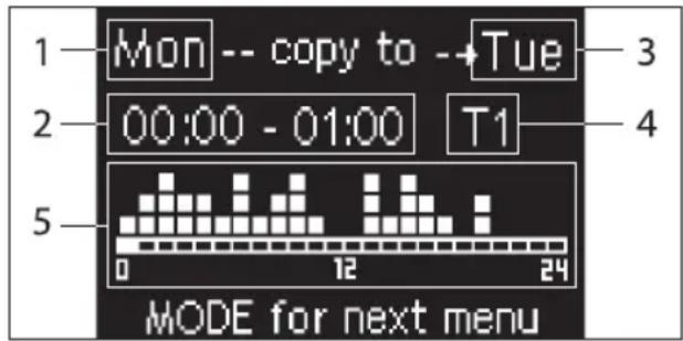
1 Mon -- copy to --Tue 2 00:00 - 01:00 T1 5 0 12 24 MODE for next menu1 DAY (PRG to edit)
2 TIME SLOT (UP/DOWN to scroll)
3 Day to copy to (UP+MODE)
4 SET POINT
5 View profile
The UP/DOWN arrows are used to scroll through the 24 time slots of every day of the week; scrolling is displayed graphically by the scroll cursor at the bottom of the screen, or in text, when the when the time slot is updated, at the top. If you wish to edit the attribute (OFF, T1, T2, T3) of a slot press SET to enter edit mode, change the attribute using the UP/DOWN ARROW and press SET again to confirm.
Press PRG to move on to the next day of the week.
To duplicate a profile press the UP ARROW and MODE keys at the same time; the day you wish to copy the profile to will be copied will be highlighted: to change it use the UP/DOWN ARROW keys and confirm with the SET key.
PARAMETERS MENU AND LISTS
To access the MENU press the PRG key. Use the UP/DOWN ARROW keys to scroll through the various MENU items, which are in the following order:
- CONFIGURATION MENU (access using password 10): see dedicated paragraph
- ADJUSTMENT MENU (access using password 77): see dedicated paragraph
- CLOCK SETUP MENU (no password required): to set date, time and day of week
• TIME SLOTS MENU (no password required)
• NETWORK AND CONNECTION MENU (access using password 20) - OUTPUT DISPLAY MENU: to view the status of the physical outputs (digital and 0-10V) on the board
- OUTPUT TEST MENU (access using password 30): forcing the physical outputs (digital and 0-10V) on the board
- INFO MENU: to view information on the installed software.
CONFIGURATION MENU
LIST OF PARAMETERS
DESCRIPTION DEFAULT POSSIBLE VALUES
| Unit type 3 speeds | 3 speeds4 speeds | |
| Number of pipes 2 Pipes 2 Pipes - 4 Pipes | ||
| Air probe Display Display - Board | ||
| Temperature display Celsius Celsius - Fahrenheit | ||
| Type of ventilation Step Step - Modulating | ||
| Valve configuration Not included | Not included - On/Off - Modulating | |
| Switching Summer/Winter | From keyboard/serial | From keyboard/serialFrom Digital inputAuto on water temp.Auto on air temp. |
| DOUT Configuration No use | (see dedicated paragraph) | |
| Digital output logic | N.A. | N.A. – N.C. |
| Heater included | No | No/Yes |
| Water probe installed | No | No/Yes |
| Number of water probes 4-pipe unit | 1 | 1/2 |
| Humidity probe installed | No | No/Yes |
| Turning Economy on from digital input | No | No/Yes |
| Turning ON/OFF on from digital input | No | No/Yes |
| Dehumidify from DIN | No | No/Yes |
| Ventilation in STANDBY | Standard | StandardAlways ONAlways OFF |
| Ventilation speed in standby | Low | Extra-lowLowMediumHigh |
| Natural convection | No | No/Yes |
| ON/OFF and SUM/WIN with disconnected serial | From keyboard | From keyboardFrom supervisor |
| Language | Italian | Italian/English |
| Stand-by Mode | Off | Off - Clock - Temperature |
Unit configuration must take the following requirements into account:
- if there is a heater you will also need a water probe to be installed:
- if there is a heater and a valve, then the valve must be a 3-WAY (NO 2-WAY VALVES);
- if Summer/Winter switching is set on "Auto on water temp." then there must also be a water probe;
• no heater must be installed on 4-pipe units; - with 4-pipe units with a single water probe, summer/winter switching cannot be set on "Auto on water temp.";
- it is only possible to set summer/winter switching on "Auto on air temp." if there is an electric heater or if the unit has 4-pipes;
- If SUMMER/WINTER switching is set on "Auto on water temp." it is not possible to use a 2-way valve. The water probe must be installed on a point in the hydraulic circuit with minimum circulation.
CONFIGURABLE DIGITAL OUTPUT
The board has a digital output (identified by 07 on the electrical diagram) and its status is linked to one of the operating statuses of the unit reported in the list below:
- Operating mode
• Cooling or heating request - Cooling request
- Heating request
• ON/OFF status of the unit - Alarm installed
- Dehumidify call
- Humidify call
• High room temperature - Low room temperature
• No water consent to heating
• No water consent to cooling - From supervisor
and selectable from the "DOUT Configuration" configuration parameter. It is also possible to choose, using the next "Digital output logic" parameter setting, whether the status of the relay needs to follow the logic NO (Normally Open) or NC (Normally Closed).
STAND-BY MODE
If no operation is performed on the user unit keyboard for 30 seconds the main screen goes into stand-by mode, which can differ based on the settings of the "Stand-by Mode" parameter, accordingly:
- Stand-by mode = Off: the display goes completely black;
- Stand-by mode = Clock: the display goes partly black and the current time and date are shown;
- Stand-by Mode = Temperature: the display goes partly black and the room temperature and any humidity are shown, if the probe is installed.
SERIAL CONNECTION FAILURE
If the serial connection fails with the controller set as SLAVE, FWECSA will either maintain the supervisor on/off settings and summer/winter mode, or it will reset the last settings entered from the keyboard, based on the relative configuration parameter.
ADJUSTMENT MENU
DESCRIPTION DEFAULT
| Minimum cooling SET limit 10.0 °C | |
| Maximum cooling SET limit 35.0 °C | |
| Minimum heating SET limit 5.0 °C | |
| Maximum heating SET limit 30.0 °C | |
| Minimum humidity SET limit 35% | |
| Maximum humidity SET limit 75% | |
| Humidity hysteresis 5% | |
| Offset on humidity reading 0% | |
| Minimum value of modulating ventilation 20% | |
| Maximum value of modulating ventilation 100% | |
| Air probe offset 0.0 °C | |
| Water probe offset 0.0 °C | |
| Heating water probe offset 0.0 °C | |
| Economy Hysteresis | 2.5 °C |
| Cooling water consent SET 22.0 °C | |
| Cooling water consent hysteresis | 5.0 °C |
| Heating water consent SET 30.0 °C | |
| Heating water consent hysteresis | 7.0 °C |
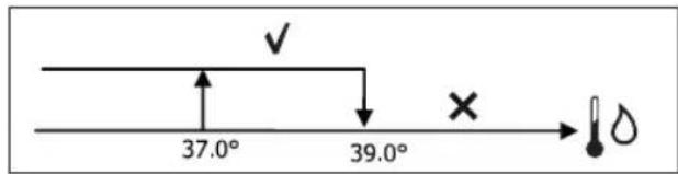
| Dehumidification water consent SET | 10.0 °C |
| Dehumidification water consent hysteresis | 2.0°C |
| Valve water consent SET | 30 °C |
| Valve water consent hysteresis | 5.0 °C |
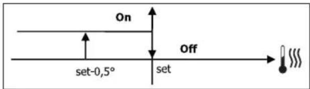
| Heater water consent SET | 39.0 °C |
| Heater water consent hysteresis | 2.0 °C |
| Temperature minimum control SET | 9.0 °C |
| Temperature minimum control hysteresis | 1.0 °C |
| Neutral zone | 5.0 °C |
| Modulating ventilation % in standby 20% 20% | |
| Default values RESET | No |
SETUP MENU
From the main display, press the UP/DOWN keys to view the following pages in this order:
• Turning Economy function on
• Enabling electrical heater use
• Turning temperature minimum control on
• Turning humidity control on
- Humidity setpoint
If it is not possible to access editing of one or more entries, you will need to preventively set the relative configuration parameters. For example, to enable electric heater operation you will need to preventively set it up in the configuration parameters menu.

Some parameters (or possible values) in the configuration, regulation and setup menus may not be accessible based on which parameter setting is selected.
ADJUSTMENT LOGIC COOLING/HEATING SWITCHING
| FAN SPEED | |
| WINTER | |
| SUMMER | |
| AIR TEMPERATURE | |
| WATER TEMPERATURE | |
| OPENING VALVE | |
| √ | YES |
| × | NO |
There are 4 different and alternative logics to select the thermostat operating modes, according to the controller configuration setting:
- Local: chosen by the user pressing the MODE key
• Distance: based on the status of digital input DI1
• depending on the water temperature
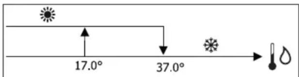
text_image
17.0° 37.0°
In case of a water probe alarm, the mode control returns temporarily to Local mode.
• depending on the air temperature
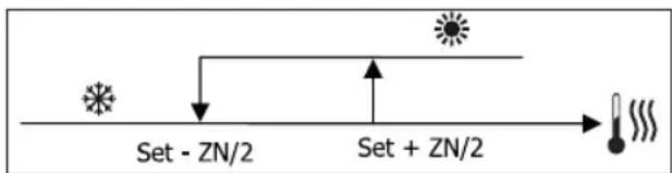
flowchart
graph LR
    A["Input"] --> B["Set - ZN/2"]
    B --> C["Process"]
    C --> D["Set + ZN/2"]
    D --> E["Output"]
Where:
• Set is the temperature set with the arrows
- NZ is the neutral zone
The operating mode of the thermostat is indicated on the display by the symbols COOLING and HEATING.
VENTILATION
GENERAL ASPECTS
The control can manage two types of ventilation:
- step ventilation with a set number of selectable speeds (3 or 4);
- modulating ventilation with variable speed between 0% and 100%
The use of one or the other type of control depends on the type of ventilator (step or modulating) installed on-board the machine. Step adjustment itself can follow two different logics based on the type of valve/s (ON/OFF or modulating). In brief, the automatic adjustment logics managed by the controller (and described in detail here below) are as follows:
- step ventilation with ON/OFF valve (or not installed) and 3 speeds, in cooling and heating mode;
- step ventilation with ON/OFF valve (or not installed) and 4 speeds, in summer and winter mode;
- step ventilation with modulating valve and 3 speeds, in summer and winter mode;
- step ventilation with modulating valve and 4 speeds, in summer and winter mode;
- modulating ventilation adjustment with ON/OFF valve, in summer and winter mode;
• modulating ventilation adjustment with modulating valve.
NATURAL CONVECTION
For units with valve, by enabling the parameter from the configuration menu, ventilation for heating is delayed by 0.5^ C to allow for an initial natural convection phase.
STEP VENTILATION
Use the UP/DOWN keys to choose from the following speeds:
- Automatic SPD.: depending on set temperature and room air temperature;
- Extra-low spd: can only be selected if the unit is 4 speeds
- Low SPEED
• Medium SPD.
• High SPD.

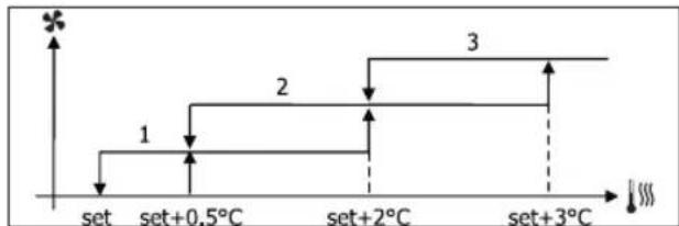
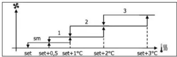
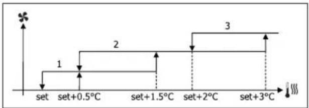
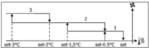
AUTOMATIC OPERATION FOR 3-SPEED UNITS AND ON/OFF VALVE/S (OR IF NOT INSTALLED):
1 Low SPEED
2 Medium SPEED
3 High SPEED
COOLING
flowchart
graph TD
    A["set"] --> B["set+0.5°C"]
    B --> C["set+2°C"]
    C --> D["set+3°C"]
    D --> E["Step 1: ↑"]
    D --> F["Step 2: ↑"]
    D --> G["Step 3: ↑"]
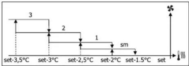
HEATING
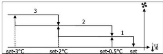
flowchart
graph TD
    A["set-3°C"] --> B["set-2°C"]
    B --> C["set-0.5°C"]
    C --> D["set"]
    style A fill:#f9f,stroke:#333
    style B fill:#f9f,stroke:#333
    style C fill:#f9f,stroke:#333
    style D fill:#f9f,stroke:#333
    note1["3"]
    note2["2"]
    note3["1"]
    note4["*"]
    note5["###"]
    note6["###"]
AUTOMATIC OPERATION FOR 4-SPEED UNITS AND ON/OFF VALVE (OR NOT INSTALLED):
1 Low SPEED
2 Medium SPEED
3 High SPEED
el EXTRA LOW SPEED
COOLING
flowchart
graph TD
    A["set"] --> B["set+0,5"]
    B --> C["set+1°C"]
    C --> D["set+2°C"]
    D --> E["set+3°C"]
    style A fill:#f9f,stroke:#333
    style E fill:#f9f,stroke:#333
    note right of B "sm"
    note left of C "1"
    note right of D "2"
    note right of E "3"
HEATING
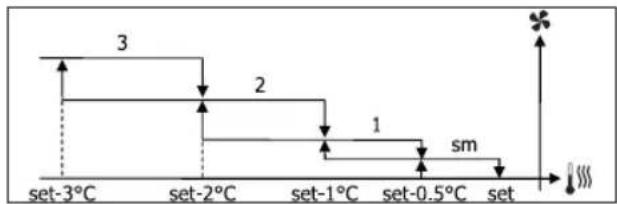
line
| Time Point | Value | |---|---| | set-3°C | 3 | | set-2°C | 2 | | set-1°C | 1 | | set-0.5°C | sm | | set | |For configurations with 4 speeds and valve, ventilation for heating is delayed by 0.5°C to allow for an initial natural convection phase.
AUTOMATIC OPERATION FOR 3-SPEED UNITS AND MODULATING VALVE/S
1 Low SPEED
2 Medium SPEED
3 High SPEED
COOLING
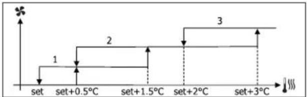
text_image
set set+0.5°C set+1.5°C set+2°C set+3°C 1 2 3HEATING
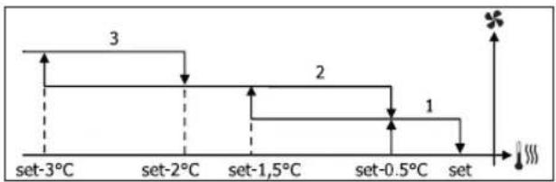
other
| Time Interval | Value | |---|---| | set-3°C | 3 | | set-2°C | | | set-1,5°C | 2 | | set-0.5°C | 1 | The chart displays a discrete stepwise increase in value from 3 to 2, followed by a decrease to 1, with an arrow pointing upward to the right (indicated by a '×' symbol). The bottom label shows '###' at the end of the sequence.AUTOMATIC OPERATION FOR 4-SPEED UNITS AND MODULATING VALVE/S:
1 Low SPEED
2 Medium SPEED
3 High SPEED
el EXTRA LOW SPEED
COOLING
flowchart
graph TD
    A["set"] --> B["set+0.5°C"]
    B --> C["set+1.5°C"]
    C --> D["set+2°C"]
    D --> E["set+3°C"]
    style A fill:#f9f,stroke:#333
    style B fill:#ccf,stroke:#333
    style C fill:#cfc,stroke:#333
    style D fill:#fcc,stroke:#333
    style E fill:#ffc,stroke:#333

HEATING
other
| Level | Value | |---|---| | set-3.5°C | 3 | | set-3°C | 2 | | set-2.5°C | 1 | | set-2°C | sm | | set-1.5°C | | | set | |MODULATING VENTILATION
As with step ventilation, the management logic for modulating ventilation offers two possible operating modes:
• AUTOMATIC operation
• fixed-speed OPERATION
The operating percentage is selected by pressing the UP/DOWN keys, while automatic ventilation comes on when ventilation is set below the minimum (20%) or above the maximum (100%) values.

MANUAL ventilation

AUTOMATIC ventilation

FORCED ventilation
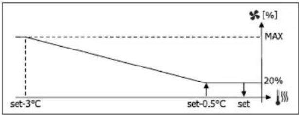
AUTOMATIC OPERATION FOR 3- OR 4-SPEED UNITS AND ON/OFF VALVE/S OR NOT INSTALLED:
COOLING
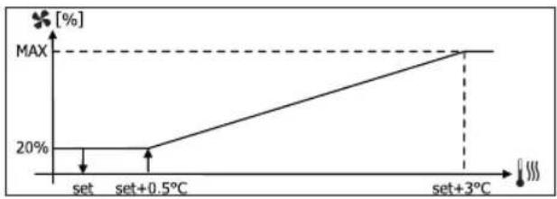
line
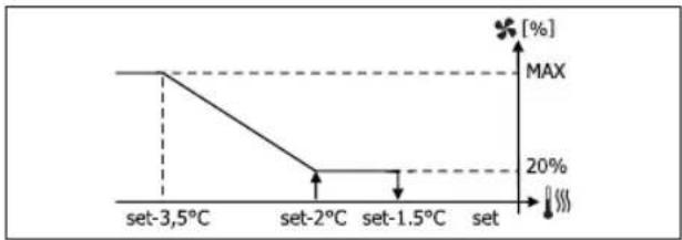
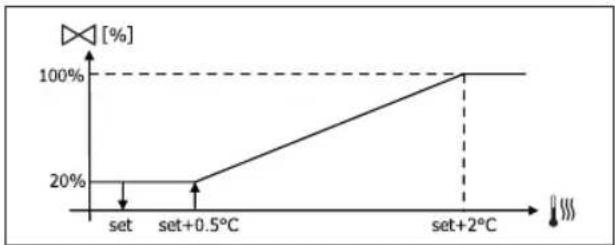
| Condition | Value [%] | |---|---| | set | 20 | | set+0.5°C | 20 | | set+3°C | MAX |HEATING WITH 3-SPEED CONFIGURATIONS
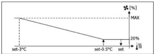
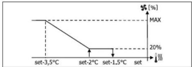
line
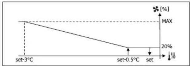
| Temperature | Value (%) | | :--- | :--- | | set-3°C | MAX | | set-0.5°C | 20 | | set | 100 |HEATING WITH 4-SPEED CONFIGURATIONS
line
| Temperature | Value [%] | | :--- | :--- | | set-3.5°C | MAX | | set-2°C | 20% | | set-1.5°C | 20% | | set | [%,] The chart displays a stepwise decreasing trend from left to right, indicating a drop in the measured variable as temperature increases from -3.5°C to -1.5°C, followed by stabilization at 20%. The maximum value is marked with a star symbol.
For configurations with 4 speeds, ventilation for heating is delayed by 0.5°C to allow for an initial natural convection phase.
WATER CONSENT
Regardless of what type of fan is installed (step or modulating), ventilation depends on the system's water temperature control. Depending on the work mode, we will have different consent thresholds for heating and cooling.
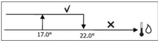
COOLING
text_image
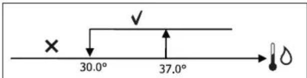
17.0° 22.0°HEATING
text_image
× 30.0° 37.0°Failure to have this consent, when the thermostat sends a signal, will be displayed by the flashing symbol of the mode that is currently in operation Cooling or Heating. This enabling signal will be ignored if:
- the water probe is not required or it is in alarm conditions because it is disconnected
• Cooling with 4-pipe configurations
FORCED OPERATIONS
Normal ventilation logic (modulating and non-modulating) will be ignored in particular forcing situations which could be necessary for the correct temperature control or functioning of the terminal.
Possible situations:
• in COOLING MODE:
- with on-board controller and configurations with valve: the minimum available speed is maintained even when the temperature is reached
- with on-board controller and configurations without valve: every 10 minutes a 2-minute washing at medium speed with the fan stopped allows the air probe to perform a more precise room temperature reading.
- if ventilation is set on standby always ON, the selected speed is maintained once the temperature setpoint is reached.
- in HEATING MODE:
- with the heater on: ventilation is forced at medium speed
- once the heater is switched off: post-ventilation is maintained at medium speed for 2 minutes. (NB: this ventilation will be completed even should the thermostat be turned off or pass to the cooling mode.)
- if ventilation is set on standby always ON, the selected speed is maintained once the temperature setpoint is reached.
VALVE
The control can manage 2- or 3-way ON/OFF (i.e. fully open or fully closed) or modulating valves (valve opening can range between 0% and 100%).
ON/OFF VALVE
Valve (2- or 3-way) opening is controlled depending on the operating setpoint and air temperature setpoint.
COOLING
text_image
Off On set set+0,5°HEATING

text_image
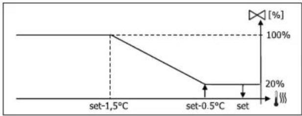
On set-0,5° Set Off setMODULATING VALVE
Valve (2- or 3-way) opening is controlled depending on the operating setpoint and air temperature setpoint. The opening adjustment logic follows the diagrams provided below.
COOLING
line
| Condition | Value [%] (%) | |---|---| | set | 20 | | set+0.5°C | 20 | | set+2°C | 100 |HEATING WITH 3-SPEED CONFIGURATIONS
line
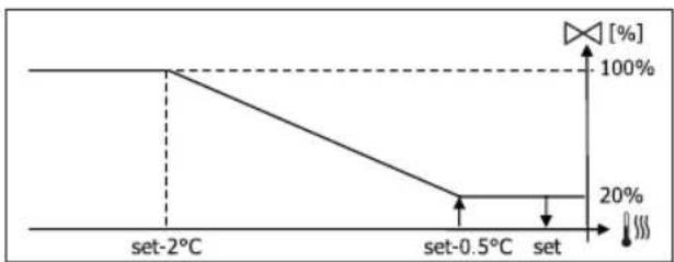
| Temperature | Percentage (%) | | :--- | :--- | | set-2°C | 100 | | set-0.5°C | 20 | | set | 100 |HEATING WITH 4-SPEED CONFIGURATIONS
line
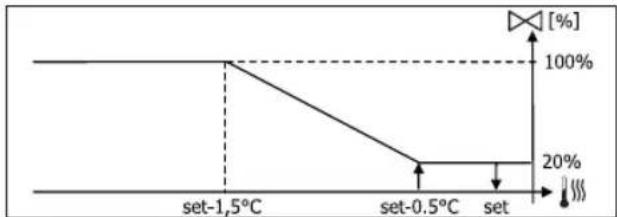
| Temperature | Percentage (%) | | :--- | :--- | | set-1.5°C | 100 | | set-0.5°C | 20 | | set | 100 |WATER CONSENT
Water temperature control for opening consent only concerns configurations with 3-way valves and electrical heater. In such configurations the water temperature will be checked in the following cases:
• Heating with heater: heater operation requires forced ventilation; it is therefore necessary to avoid water that is too cold from passing through the unit.
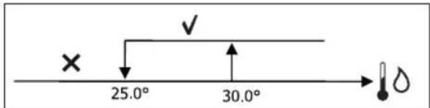
text_image
× 25.0° 30.0°- Post ventilation due to the heater switching off: maintained until the end of the set time, even if the operation mode is changed. During post-ventilation water consent coincides with consent required for ventilation.
ELECTRICAL HEATER
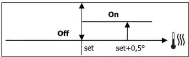
SWITCHING IT ON
If it has been preventively included by the configuration parameter and use is enabled by the setup parameter, the electrical heater is used when the thermostats requires it, based on the room temperature:
text_image
On set-0,5° Set Off Set
Switching it on entails forced ventilation.
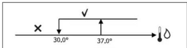
WATER CONSENT
Consent to switch on the heater depends on water temperature control. The following is the relative consent logic:
HEATING
text_image
37.0° 39.0°This enabling signal will not be given if the water probe is not included or is disconnected.
ECONOMY
If it has been preventively included by the configuration parameter and use is enabled by the setup parameter, the Economy function will correct the setpoint by 2.5°C and force operation at the minimum available seed to reduce unit operation.
• Cooling: set + 2.5°C
• Heating: set - 2.5°C
MINIMUM TEMPERATURE CONTROL
If it has been preventively included by the configuration parameter and use is enabled by the setup parameter, when the thermostat is off, this logic avoids the room temperature from dropping below a settable threshold ("Minimum temperature control SET"), forcing the unit to heating mode for the required amount of time.
If the electrical heater is present, it will be used only if it was previously selected as a resource in the Heating mode.
SWITCHING IT ON
If this control is selected, the terminal will turn on if the room temperature falls below 9^ C:
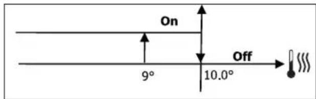
text_image
On 9° 10.0° OffOnce the temperature returns above 10^ C, the thermostat will go back Off.

Pressing OFF on the digital input will deactivate this logic.
DEHUMIDIFICATION
The dehumidification function, which can only be used in Cooling mode, if a humidity probe has been included in the configuration menu, makes the unit operate with the aim of reducing any humidity in the room, until it reaches the setpoint level entered in the setup menu parameter.
LOGIC
Ventilation speed will be forced to low, or, if the temperature is much higher than the entered set, to medium speed.
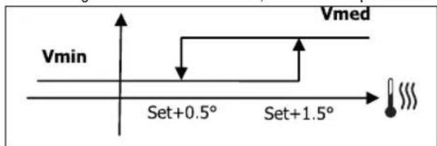
text_image
Vmin Set+0.5° Set+1.5° VmedThey must bring humidity back to the set value (and the valve, if installed), ventilation will switch on even if the room temperature has already reached the relative set (shown on the display). If it drops too far below this threshold, the logic will be temporarily disabled.
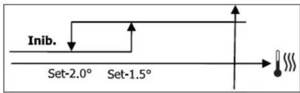
text_image
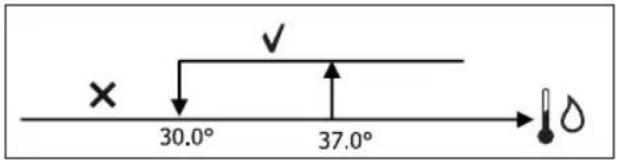
Inib. Set-2.0° Set-1.5°WATER CONSENT
Consent to switch on dehumidification depends on water temperature control. The following is the relative consent logic:
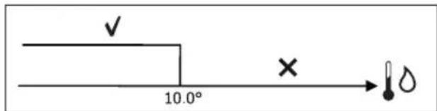
text_image
✓ 10.0° × →If there is no consent the dehumidification function will be momentarily disabled. This will also happen if the probe is disconnected.

Once the reference humidity level is reached or the controller is placed on Off, dehumidification will switch off.
ALARMS
The alarms managed by the controller refer to missing probes required by the unit's configuration. Accordingly, the following are possible alarms:
• Air probe alarm
• Water probe alarm
• Humidity probe alarm
NETWORKS AND CONNECTIVITY
CONNECTION TO SUPERVISION SYSTEM (EXTERNAL SUPERVISOR SYSTEM SOLUTION)

Connection is possible for version External Supervisor System 3.10 or higher.
Using serial port RS485 it is possible to connect FWECSA controllers (up to 247) to a management software that uses standard MODBUS RTU as a communication protocol, with the following characteristics:
• settable baudrate (defualt: 9600);
- no parity
- 8 bits of data
• 1 bit of stops
Inside a supervision network, each FWECSA controller acts as a SLAVE towards the centralised management system which constitutes the network MASTER (figure 01).
Once the network has been wired, it is necessary to configure each FWECSA controller. Press PRG to access the MENU and then enter sub-menu "Networks and connections" (password = 20). Set the SETUP RS485 parameters as follows:
• MST/SLV = "Slave from SPV"
- Protocol = "Modbus"
- Serial address = set a value between 1 and 255
- Speed = set based on the requirements of the Master leave the SETUP OC PARAMETERS UNCHANGED (MST/SLV = none).

For details on how to wire the network, read "RS485 NETWORK GUIDE LINES" available in the download area of the Daikin website.
The following functions are recognised and managed by the
controller as SLAVE:
CODE DESCRIPTION
| 01 coil status reading |
| 02 input status reading |
| 03 holding register reading |
| 04 input register reading |
| 15 multiple coil status writing |
| 16 multiple holding register writing |
The following are the available variables:
COIL STATUS (DIGITAL READING/WRITING)
DESCRIPTION
| 1 ON/OFF controller |
| 2 SUMMER/WINTER controller |
| 3 ECONOMY controller |
| 4 ENABLE ANTI-FREEZE controller |
| 5 ENABLE ELECTRICAL HEATER controller |
| 6 modulating ventilation MAN/AUTO controller |
| 7 enable ON/OFF from MASTER |
| 8 enable ECONOMY from MASTER |
| 9 enable SUMMER/WINTER from MASTER |
| 10 enable ANTI-FREEZE from MASTER |
| 11 enable ELECTRIC HEATERS from MASTER |
| 12 enable SETPOINT from MASTER |
| 13 enable SETPOINT LIMITS from MASTER |
| 14 enable VENTILATION SPEED from MASTER |
| 15 KEYBOARD LOCK controller |
| 16 enable HUMIDITY CONTROL consent from MASTER |
| 17 enable HUMIDITY CONTROL |
| 18 control for CONFIGURABLE DIGITAL OUTPUT NO.7 |
INPUT STATUS (READ-ONLY DIGITAL)
| DESCRIPTION |
| 1 unit ON/OFF |
| 2 SUMMER/WINTER |
| 3 ECONOMY on |
| 4 ANTI-FREEZE on |
| 5 ALARM installed |
| 6 Room temperature probe alarm |
| 7 Water temperature probe alarm |
| 8 Hot water temperature probe alarm(only with 4-pipe units) |
| 9 Room humidity probe alarm |
| 10 Speed number (3/4) |
| 11 Pipe number (2/4) |
| 12 Type of ventilation (STEP/MODULATING) |
| 13 Adjustment probe (DISPLAY/BOARD) |
| 14 Installed electrical heaters |
| 15 Installed humidity probe |
| 16 Digital output 1 status (01) |
| 17 Digital output 2 status (02) |
| 18 Digital output 3 status (03) |
| 19 Digital output 4 status (04) |
| 20 Digital output 5 status (05) |
| 21 Digital output 6 status (06) |
| 22 Digital output 7 status (07) |
| 23 Water probe presence |
| 24 Hot water probe presence (hydronic unit with 4 pipes) |
| 25 Dehumidification active |
| 26 Valve open |
| 27 Hydronic unit switched off from remote contact |
| 28 Ventilation control (manual/automatic) |
| 29 Heater active |
| 30 Valve presence |
| 31 Enable ECONOMY from contact |
HOLDING REGISTER
(READING/WRITING WHOLES/ANALOGUES)
| DESCRIPTION | |
| 1 | Summer temperature SET (cooling) |
| 2 | Summer temperature SET minimum limit |
| 3 | Summer temperature SET maximum limit |
| 4 | Winter temperature SET (heating) |
| 5 | Winter temperature SET minimum limit |
| 6 | Winter temperature SET maximum limit |
| 7 | Single temperature SET(if SUM/WIN on water/air temp.) |
| 8 | Humidity SET |
| 9 | Minimum humidity SET limit |
| 10 | Maximum humidity SET limit |
| 11 | Step ventilation speeds:0 = extra-low speed1 = low speed2 = medium speed3 = maximum speed4 = AUTO speed |
| 12 | Modulating ventilation speed |
INPUT REGISTER
(READ-ONLY WHOLES/ANALOGUES)
| DESCRIPTION | |
| 1 Room temperature | |
| 2 Room humidity | |
| 3 Water temperature | |
| 4 Hot water temperature (only with 4-pipe units) | |
| 5 | Step ventilation status:0 = no ventilation1 = extra-low speed2 = low speed3 = medium speed4 = maximum speed |
| 6 Modulating ventilation % value | |
| 7 % | value of analogue output 1 |
| 8 % | value of analogue output 2 |
| 9 % | value of analogue output 3 |
| 10 Temperature SET on | |
| 11 Summer temperature SET | |
| 12 Winter temperature SET | |
| 13 | Single temperature SET(if SUM/WIN on water/air temp.) |
| 14 Humidity SET on | |
| 15 Type of valve (NOT INCLUDED/ON-OFF/MODULATING) | |
"SMALL" NETWORK SOLUTIONS
“SMALL” network solutions constitute a MASTER/SLAVE network system where one of the FWECSA controllers performs the function of MASTER while all of the other FWECSA controllers on the network perform the SLAVE function.
It can be set up in two different ways, each with different functions and type of connection:
• SMALL network on RS485
• SMALL network on CONVEYED WAVES
SMALL NETWORK ON RS485
In this case the connection is set up using bus RS485, comprised of a twisted 2-conductor, shielded data cable (figure 02).
i
For details on how to wire the network, read "RS485 NETWORK GUIDE LINES" available in the download area of the Daikin website.
The MASTER controller sends the following settings to the SLAVE controller:
• Operating mode: (COOLING or HEATING);
- ON/OFF status of the controller: all of the SLAVE controllers switch to the ON/OFF status of the MASTER controller;
• Enabling minimum room temperature control;
• Room temperature SET;
or (based on the "Temperature control from MASTER" parameter in the "Networks and Connections" menu):
- Limits that apply to changes in the room temperature SET (both SUMMER and WINTER): on each SLAVE controller, the SET variation is allowed with a delta of ±2^ around the value of the SET entered on the MASTER controller.
In terms of the ON/OFF status, the following is allowed on each SLAVE controller:
- Automatic local ON when requested by the minimum room air temperature control function.
- Automatic local ON/OFF depending on the time slots, if enabled;
- OFF on SLAVE controller from digital input if it is enabled.
Each SLAVE controller maintains its autonomy in managing ventilation speed, in switching the ECONOMY function on and in setting the SET value (with the limits described above).
This type of network does not allow a supervision network to be included (External Supervisor System solution) as the RS485 serial ports on all of the controllers (both MASTER and SLAVE) are already occupied by the SMALL network arrangement.
Once the network has been wired, it is necessary to configure each FWECSA controller. Press PRG to access the MENU and then enter sub-menu "Networks and connections" (password = 20). Set the SETUP RS485 parameters as follows:
- MST/SLV = set "Master" on the FWECSA controller acting as the MASTER on the network, and set "Local Slave" on all of the FWECSA controllers acting as the SLAVEs in the network.
- Protocol = "Modbus"
- Serial address = set a value between 1 and 255, only in the SLAVE controllers.
• Speed = do not change (9600)
Leave the SETUP OC PARAMETERS UNCHANGED (MST/SLV = none).
SMALL NETWORK ON CONVEYED WAVES
This type of configuration controls up to a maximum of 32 hydronic units through a single user unit.
The connection is set up using an OC bus, comprised of a twisted 2-conductor, shielded data cable (figure 03).
In this case, the MASTER controller makes all of the SLAVE controllers connected to the network operate (instant by instant) in an identical fashion to the MASTER controller itself. Accordingly, no SLAVE controller can make autonomous decisions, nor are they equipped with their own user unit.
The maximum number of SLAVE controllers that can be connected to this type of network is 32.
Before connecting the I/O boards to the network, each board needs to be configured.
Connect the user unit to each I/O board.
Press PRG to access the MENU and then enter sub-menu "Networks and connections" (password = 20). Set the OC

SETUP parameters as follows:
- MST/SLV = set "Master" on the I/O board acting as the MASTER of the network and "Slave" on all of the SLAVEs in the network.
- Serial address = set a value between 2 and 34 on the SLAVE controllers.
It is now possible to connect all of the I/O boards to the network.

Once the board has been set as SLAVE, it can no longer communicate with any random user unit. Accordingly, if the settings are changed, it will be necessary to RESET it in the following manner: disconnect the board from the network and, keeping it powered, place digital input 10 in short circuit for 15 seconds (clamps I10 and IC).

All of the hydronic units (i.e. both MASTER and SLAVE) connected to the network must be configured in the same way.
MIXED NETWORK
The SMALL network on CONVEYED WAVES can also be connected to a supervision network (External Supervisor System or SMALL solution) on RS485 through RS485 serial port of the MASTER controller, thus obtaining what is known as a MIXED NETWORK. Figure 04 illustrates the diagram of a mixed network comprised of a SMALL network on CONVEYED WAVES combined with a supervision network.
PARAMETER OUTLINING TABLE
| RS485 | EXTERNAL SUPERVISOR SYSTEM BMS | SMALL RS485 | SMALL OC | Mixed Network |
| MST/SLV | Slave from SPV | FWECSA Master: Master | - | FWECSA Master: Master |
| FWECSA Slave: Slave from SPV | FWECSA Slave: Slave from SPV | |||
| Protocol Modbus | Modbus - Modbus | |||
| Serial Address | 1... 255 | FWECSA Master: 0 | - | FWECSA Master: 0 |
| FWECSA Slave: 1... 255 | FWECSA Slave: 1... 255 | |||
| Speed | Based on the Master | 9600 - 9600 | ||
| OC | ||||
| MST/SLV - - | FWECSA Master: Master | |||
| FWECSA Slave: Slave | ||||
| Serial Address | - | FWECSA Master: 0 | ||
| FWECSA Slave: 2... 255 | ||||
MEANINGS OF THE LEDS
| BLUE GREEN RED | |||
| STATUS LED | Unit OFF Unit | ON | Alarm in progress |
| NETWORK LED | OC Master | Communication OK | No communication |
i Looking at the I/O board from the front, the STATUS LED is on the left, while the NETWORK LED is on the right.

TECHNICAL DATA
| Power supply 230Vac 50/60Hz | |
| Operating Temperature | Range 0-50°C |
| Storage Temperature Range -10-60°C | |
| IP protection rating IP30 (user unit) | |
| Type of board Type 1.C | |
| Output relay Normal Open 5A @ 240V (Resistive)Max room temperature: 105°CMicro-interruption | |
| Inputs NTC Temperature | Probes0-5V probes onDry contacts (digital inputs) |
| Temperature Probes NTC probes 10K Ohm @25°CRange -25-100°C | |
| Humidity probe Resistive type of probeRange 20-90%RH | |
| Max cable section for clamps | 1.5 mm ^2 |
| Pollution rating Degree II | |
| Heat/fire resistance Category D | |
| Over-voltage category Category II | |
| EMC conformity standards | EN 61000-6-1(2007)EN 61000-6-3(2007) + A1(2011) |
INSTALLATION AND MAINTENANCE
The procedures for installing the user interface, the power board and probes, with specific instructions for individual hydronic units of the Daikin range, will be described at a later stage.
PROBE INSTALLATION
The FWECSA controller manages the following probes:
- Air temperature reading probe installed inside the user unit; it does not require any special installation operations.
- Probe (optional and alternative to the previous one) connected to the I/O board for temperature readings of the air taken in by the machine, or in any other point of the room subject to temperature adjustment (REMOTE AIR PROBE)
- Probes (optional) for water temperature readings: it is possible to connect one or two probes, depending on whether the unit is connected to a 2- or 4-pipe system.
- Probe (optional) to read the relative ambient humidity, connected to the I/O board

To avoid interference, and subsequent faulty operation, the probe cables must NOT be set up near power cables 8230V).
REMOTE AIR PROBE INSTALLATION
Use of the remote air probe to adjust the room temperature is optional. When it is used, it becomes the main adjustment probe, in place of the probe installed inside the user unit. It is always possible to choose the main room temperature adjustment probe from the "air probe" parameter contained in the CONFIGURATION MENU.
The remote air probe must always be connected to clamps I1-C1 on the I/O board.
Use the supplied adhesive plastic probe-holder:
• Fan coil without base (figure 05)
• Fan coil with base (figure 06)
• Fan coil with front suction (figure 07)
HUMIDITY PROBE INSTALLATION
The humidity probe is an optional accessory. If one is installed, it must be connected to the SU-SU clamps on the I/O board. The probe sensor can be positioned where it will be in contact with the air flow of the unit's suction circuit (if there is also a remote temperature probe, strap them together as illustrated in the figure below) or in any other point in the room subject to temperature and humidity adjustment.
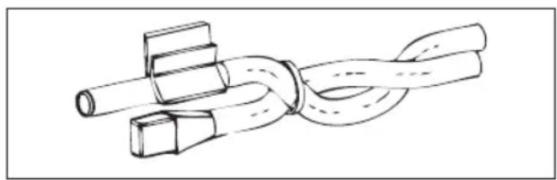
natural_image
Diagram of a rope knot with two connectors (no text or symbols)IT IS also possible to position the probe sensor inside the user unit using the relative hook on the base of the unit (figure 08).
The cable supplied with the humidity sensor is equipped with a shield. There is no need to connect this shield to the I/O board. If interference from near-by power cables or other is affecting the relative humidity reading, connect the aforementioned shield to the GND clamp on the RS485 serial port.
WATER PROBE INSTALLATION
The water temperature detection probe (white cable) is an optional accessory.
With 2-pipe units (single coil) the water probe must be connected to clamps I2 - C1 of the I/O board. With 4-pipe units it is possible to choose (through the "Number of water probes" parameter in the CONFIGURATION MENU) how many probes (one or two) to use. If you choose to use a water probe, it must be installed so that it reads the
temperature of the heating water (and is therefore installed on the hot water coil) and must be connected to clamps I2 - C1 of the I/O board. If, on the other hand, you choose to use two water probes, the cold water detection probe must be connected to clamps I2 - C1 of the I/O board, whereas the hot water detection probe must be connected to clamps I3 - C1 of the I/O board.
Use the copper probe-holder for the water probe and, depending on the case, set it up as described below. Fan coils for:
- 2-PIPE system - NO VALVE or 2-WAY VALVE: the water probe must be set up on the exchanger (figure 09);
- 2-PIPE system - NO VALVE or 2-WAY VALVE: the water probe (if single) must be set up on the exchanger in the heating circuit (figure 10); any second probe must be installed on the exchanger in the cooling circuit;
- 2-PIPE system - WITH 3-WAY VALVE: the water probe must be positioned on the valve entrance, on the branch leading out from the system (figure 11);
- 4-PIPE system - WITH 3-WAY VALVES: the water probe (if single) must be positioned on the entrance of the heating valve, on the branch leading out from the circuit (figure 12); any second probe must be installed on the entrance of the cooling valve on the branch leading out from the circuit.
FWD
Example, valves installed on the left side:
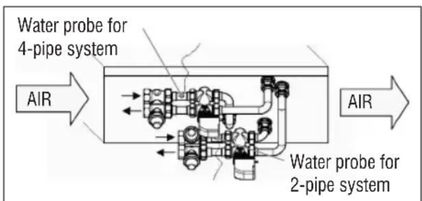
text_image
Water probe for 4-pipe system AIR Water probe for 2-pipe system AIR- For FWD units without valves, for 2-pipe systems, the water probe must be positioned on the pipe at the entrance of the exchanger.
- For FWD units without valves, for 4-pipe systems, the water probe must be positioned on the pipe at the
entrance of the exchanger in the heating circuit.
FWB-FWP
Example, valves installed on the left side:
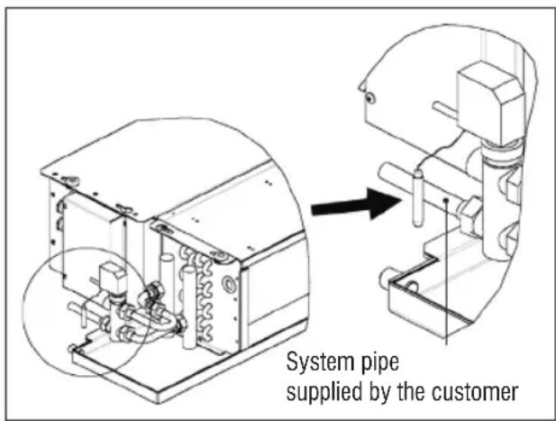
text_image
System pipe supplied by the customer- For FWB-FWP units without valves, for 2-pipe systems, the water probe must be positioned on the pipe at the entrance of the exchanger.
- For FWB-FWP units without valves, for 4-pipe systems, the water probe must be positioned on the pipe at the entrance of the exchanger in the heating circuit.
USER UNIT INSTALLATION
Choose an area to install the controller panel which is easily accessible to set functions and efficient for room temperature detection (at least 1.5 m from the floor). Therefore, avoid:
• direct sunlight exposure;
• direct exposure to hot or cold air currents;
- placing obstacles which impair correct temperature detection (curtains or furniture);
• the constant presence of water vapour (kitchens, etc.):
• covering or recessing the panel into the wall.
For wall installation of the controller, it is advisable to use a recessed 503 electrical contact box behind the controller to house the wires. For installation, follow the instructions below:
- Remove the controller's closing screw (figure 13).
- If a 503 enclosed gang box is used, pass the cables through the slot at the bottom of the controller and use the relative holes for fastening (figure 13).
- Otherwise drill a hole in the wall, for the fastening holes on the base of the controller, where you wish to install the controller. Use the base of the controller as a template to mark the position of the holes. Pass the cables through the slots on the base and fasten it with plugs onto the previously drilled wall (figure 14).
- Connect the clamp to the display board.
- Close the controller back up using the closing screw.
The connection between the panel and the controller and the I/O board must be set up using the 2-clamp connectors for conveyed waves installed on both devices (see electrical diagram). With the I/O board, there are 2 connectors to set up the connection: it makes no difference which connector is used. It is necessary to use a data cable for networks with a pair of twisted conductors and shielding. It is also necessary to connect the shielding conductor to the clamp (-) on the user side and on the I/O board (figure 19).
ON-BOARD I/O BOARD INSTALLATION
FWV, FWL, FWM, FWZ, FWR, FWS, FWD"
- Install the I/O board on FWD-FWB-FWP-FWZ-FWV-FWR-FWL-FWS-FWM units using the relative clamping bracket and the supplied 9.5 mm screws (figure 15-16-17);
- Screw the 3-way terminal board onto the bracket using the supplied 25 mm screws;
• Install the bracket onto the side of the unit that is opposite the water infeed/outfeed manifolds; - Set up the electrical connections as illustrated in the electrical diagram (figure 19); use the cable with a 1.5mm^2 section to connect the unit terminal board (CN) to the board.
FWB-FWP
- On the FWB-FWP unit, install the I/O board directly onto the electrical connections box using the supplied 9.5 mm screws (figure 18).
- Set up the electrical connections as illustrated in the electrical diagram (figure 19); use the cable with a 1.5mm^2 section to connect the unit terminal board (CN) to the board.
ELECTRICAL CONNECTIONS
All of the operations must be carried out by qualified staff, in accordance with regulations in force. For any electrical-related procedure, refer to the electrical diagrams supplied with the unit. We also suggest making sure that the characteristics of the electrical network are suitable for the absorption levels reported in the electrical data table.

Before carrying out any operation on electrical parts, make sure the power supply is disconnected. Check that the mains voltage is compatible with the specifications of the unit (voltage, number of phases, frequency) shown on the unit rating plate. The supply voltage must not fluctuate by more than ±5% in relation to the rated value. The electrical connections must be set up according to the electrical diagram attached to the specific unit and with the regulations in force.
MAINTENANCE

Maintenance operations must be carried out exclusively by a manufacturer-authorised assistance centre or by qualified staff. For safety reasons, before carrying out any maintenance or cleaning, turn the equipment off.
I/O TABLE FOR THE BOARD (figure 19)
POWER SUPPLY
| L Phase | |
| N Neutral | |
| INPUTS | |
| I1 Room air NTC probe | |
| I2 Water NTC probe | |
| I3 Hot water NTC probe (with 4-pipe units) | |
| I4 Not used | |
| I5 Not used | |
| IC Common for NTC probes | |
| +5 Not used | |
| I6 Input for remote ON/OFF | |
| I7 Input for remote SUM/WIN | |
| I8 Input for remote ECONOMY | |
| I9 Not used | |
| I10 Not used | |
| IC Common for I6-I7-I8 | |
| SU - SU Humidity probe | |
OUTPUTS
| A1 Brushless fan modulation | |
| A2 | Water valve modulation (cold with 4-pipe units) |
| A3 Hot water valve modulation (only with 4-pipe units) | |
| CA Common for 0-10V outputs | |
| O1 Extra-low speed | |
| O2 Low Speed | |
| O3 Medium Speed | |
| O4 High Speed | |
| O5 Water valve (cold with 4-pipe units) | |
| O6 Hot water valve (only with 4-pipe units) or heater | |
| C1 Common for 01-06 relay outputs | |
| O7 Configurable signal output | |
| C7 Common for 07 relay output | |
| PORTS (FRONT OF BOARD) | |
| A/B/GND R$485 serial MODBUS protocol | |
| + / - Display connection or second board | |
| + / - Display connection or second board | |
ELECTRICAL DIAGRAM (figure 19)
| KEY | |
| SA Room temperature probe | |
| SW Water temperature probe (cold with 4-pipe units) | |
| SWH | Hot water temperature probe (only with 4-pipe units) |
| SU Ambient humidity probe | |
| ON/OFF Dry contact for remote ON/OFF | |
| SUM/WIN Dry contact for remote SUMMER/WINTER | |
| ECONOMY Dry contact for remote ECONOMY | |
| FAN 0/10V Modulating fan 0/10V | |
| VH 0/10V | Modulating 0/10V water valve (cold with 4-pipe units) |
| VH 0/10V Modulating hot water valve (only with 4-pipe units) | |
| MV Fan | |
| INV | Fan inverter |
| MV INV | Inverter fan motor |
| V1 Extra-low speed | |
| V2 Low speed | |
| V3 Medium speed | |
| V4 Maximum speed | |
| COM | Common for ON/OFF outputs |
| VC Water valve (cold with 4-pipe units) | |
| VH/RE | Cold water valve (only with 4-pipe units) or electric heater |
| CN Unit terminal board | |
| IL Line switch (not included) | |
| F Fuse (not included) | |
| L Phase | |
| N Neutral | |
SOMMAIRE
SYMBOLES DE SÉCURITÉ .... 1
MISES EN GARDE GÉNÉRALES .... 1
CARACTÉRISTIQUES PRINCIPALES....2
FONCTIONS PRINCIPALES ...... 2
TERMINAL UTILISATEUR.... 3
CLAVIER....3
COMBINAISON DES TOUCHES....4
ALLUMER/ÉTEINDRE L'UNITÉ....4
MODIFIER POINTS DE CONSIGNE DE TEMPÉRATURE ET VITESSES DE VENTILATION...... 4
MODIFIER LE MODE DE FONCTIONNEMENT ....5
ACTIVER/DÉSACTIVER LA FONCTION ECONOMY ....5
ACTIVER/DÉSACTIVER L'INTERVENTION DES RÉSISTANCES ÉLECTRIQUES......5
ACTIVER/DÉSACTIVER LE CONTRÔLE DE LA TEMPÉRATURE MINIMUM AMBIANTE......5
ACTIVER/DÉSACTIVER LE CONTRÔLE DE L'HUMIDITÉ AMBIANTE....5
MODIFIER LE POINT DE CONSIGNE D'HUMIDITÉ ....5
ACTIVER/DÉSACTIVER LES PLAGES HORAIRES....6
AFFICHER LA TEMPÉRATURE DE L'EAU 6
BLOQUER/DÉBLOQUER LE CLAVIER....6
AFFICHER L'HEURE ET LA DATE....6
MODIFIER LES DONNÉES DE L'HORLOGE....6
CONFIGURER LES PLAGES HORAIRES....6
MENUS ET LISTES DES PARAMÈTRES....7
INSTALLATION SONDES ....20
INSTALLATION DE LA SONDE À AIR À DISTANCE....20
INSTALLATION DE LA SONDE D'HUMIDITÉ....21
INSTALLATION DE LA SONDE DE L'EAU ....21
INSTALLATION DU TERMINAL DE L'UTILISATEUR....23
INSTALLATION À BORD DE LA CARTE I/O....23
BRANCHEMENTS ÉLECTRIQUES ......23
ENTRETIEN 23
TABLEAU I/O DE LA CARTE....24
SCHÉMA ÉLECTRIQUE....24

AVERTISSEMENT

MAINTENIR SÉPARÉS LES CÂBLES DE DONNÉES DE CEUX DE PUISSANCE

SYMBOLES DE SÉCURITÉ

LIRE ATTENTIVEMENT

ATTENTION

DANGER TENSION
DO NOT PULL
DO NOT FORCE
MISES EN GARDE GÉNÉRALES
TOUCHE SET (POINT DE CONSIGNE)
| DESCRIPTION DÉFAUT | VALEURS POSSIBLES | |
| Unit type 3 speeds | 3 speeds4 speeds | |
| Number of pipes 2 Pipes - 4 Pipes | ||
| Air probe Display Display - Board | ||
| Temperature display Celsius Celsius - Fahrenheit | ||
| Type of ventilation Step Step - Modulating | ||
| Valve configuration | Not included | Not included - On/Off - Modulating |
| Switching Summer/Winter | From keyboard/serial | From keyboard/serialFrom Digital inputAuto on water temp.Auto on air temp. |
| DOUT Configuration No use | (see dedicated paragraph) | |
| Digital output logic | N.A. | N.A. – N.C. |
| Heater included | No | No/Yes |
| Water probe installed | No | No/Yes |
| Number of water probes 4-pipe unit | 1 | 1/2 |
| Humidity probe installed | No | No/Yes |
| Turning Economy on from digital input | No | No/Yes |
| Turning ON/OFF on from digital input | No | No/Yes |
| Dehumidify from DIN | No | No/Yes |
| Ventilation in STANDBY | Standard | StandardAlways ONAlways OFF |
| Ventilation speed in standby | Low | Extra-lowLowMediumHigh |
| Natural convection | No | No/Yes |
| ON/OFF and SUM/WIN with disconnected serial | From keyboard | From keyboardFrom supervisor |
| Language | Italian | Italian/English |
| Stand-by Mode | Off | Off - Clock - Temperature |
CONTRAINTES DE CONFIGURATION
| Minimum cooling SET limit 10.0 °C | |
| Maximum cooling SET limit 35.0 °C | |
| Minimum heating SET limit 5.0 °C | |
| Maximum heating SET limit 30.0 °C | |
| Minimum humidity SET limit 35% | |
| Maximum humidity SET limit 75% | |
| Humidity hysteresis 5% | |
| Offset on humidity reading 0% | |
| Minimum value of modulating ventilation 20% | |
| Maximum value of modulating ventilation 100% | |
| Air probe offset 0.0 °C | |
| Water probe offset 0.0 °C | |
| Heating water probe offset 0.0 °C | |
| Economy Hysteresis 2.5 °C | |
| Cooling water consent SET 22.0 °C | |
| Cooling water consent hysteresis | 5.0 °C |
| Heating water consent SET 30.0 °C | |
| Heating water consent hysteresis | 7.0 °C |
| Dehumidification water consent SET | 10.0 °C |
| Dehumidification water consent hysteresis | 2.0°C |
| Valve water consent SET | 30 °C |
| Valve water consent hysteresis | 5.0 °C |
| Heater water consent SET | 39.0 °C |
| Heater water consent hysteresis | 2.0 °C |
| Temperature minimum control SET | 9.0 °C |
| Temperature minimum control hysteresis | 1.0 °C |
| Neutral zone | 5.0 °C |
| Modulating ventilation % in standby 20% 20% | |
| Default values RESET | No |
LE MENU SETUP
text_image
17.0° 37.0°
text_image
set set+0.5°C set+1.5°C set+2°C set+3°C 1 2 3CHAUFFAGE
line
| Time Point | Value | |---|---| | set-3°C | 3 | | set-2°C | | | set-1,5°C | 2 | | set-0.5°C | 1 | The chart displays a discrete decreasing trend of the measured variable as temperature increases from -3°C to 0.5°C, with a separate vertical marker indicating a value of 1 and a star symbol indicating a turning point. The x-axis is labeled 'set' and the y-axis is unlabeled but represents the magnitude of the measured variable.line
| Condition | Value [%] | |---|---| | set | 20 | | set+0.5°C | 20 | | set+3°C | MAX (plateau) |CHAUFFAGE AVEC CONFIGURATIONS À 3 VITESSES
line
| Temperature | Value (%) | | :--- | :--- | | set-3°C | 20 | | set-0.5°C | 20 | | set | MAX |CHAUFFAGE AVEC CONFIGURATIONS À 4 VITESSES

line
| Temperature | Value (%) | | :--- | :--- | | set-3.5°C | MAX | | set-2°C | 20 | | set-1.5°C | 20 | | set | [%] |
text_image
17.0° 22.0°CHAUFFAGE

text_image
× 30.0° 37.0°line
| Condition | Value (%) | |---|---| | set-2°C | 100 | | set-0.5°C | 20 | | set | 20 | The chart displays a single line representing a decreasing trend from left to right, with a dashed vertical line at set-2°C and a horizontal line at the bottom of the plot. The y-axis is labeled [(%)] and the x-axis is labeled 'set'. The legend is not present in the image.CHAUFFAGE AVEC CONFIGURATIONS À 4 VITESSES
line
| Temperature | Percentage (%) | | :--- | :--- | | set-1.5°C | 100 | | set-0.5°C | 20 | | set | 20 |COMMANDE DE L'EAU
text_image
× 25.0° 30.0°text_image
37.0° 39.0°text_image
On 9° 10.0° Offtext_image
Vmin Set+0.5° Set+1.5° Vmedtext_image
Inib. Set-2.0° Set-1.5°COMMANDE DE L'EAU
text_image
✓ 10.0° × →natural_image
Diagram of a rope knot with two connectors (no text or symbols)FWV, FWL, FWM, FWZ, FWR, FWS, FWD
| BESCHREIBUNG DEFAULT | MÖGLICHE WERTE | |
| Unit type 3 speeds | 3 speeds4 speeds | |
| Number of pipes 2 Pipes | 2 Pipes - 4 Pipes | |
| Air probe Display Display | - Board | |
| Temperature display Celsius | Celsius - Fahrenheit | |
| Type of ventilation Step | Step - Modulating | |
| Valve configuration Not included | Not included- On/Off - Modulating | |
| Switching Summer/Winter | From keyboard/ serial | From keyboard/ serialFrom Digital inputAuto on water temp.Auto on air temp. |
| DOUT Configuration | No use | (see dedicated paragraph) |
| Digital output logic | N.A. | N.A. – N.C. |
| Heater included | No | No/Yes |
| Water probe installed | No | No/Yes |
| Number of water probes 4-pipe unit | 1 | 1/2 |
| Humidity probe installed | No | No/Yes |
| Turning Economy on from digital input | No | No/Yes |
| Turning ON/OFF on from digital input | No | No/Yes |
| Dehumidify from DIN | No | No/Yes |
| Ventilation in STANDBY | Standard | StandardAlways ONAlways OFF |
| Ventilation speed in standby | Low | Extra-lowLowMediumHigh |
| Natural convection | No | No/Yes |
| ON/OFF and SUM/ WIN with disconnected serial | From keyboard | From keyboardFrom supervisor |
| Language | Italian | Italian/English |
| Stand-by Mode | Off | Off - Clock - Temperature |
BEDINGUNGEN FÜR DIE KONFIGURATION
| BESCHREIBUNG DEFAULT | |
| Minimum cooling SET limit 10.0 °C | |
| Maximum cooling SET limit 35.0 °C | |
| Minimum heating SET limit 5.0 °C | |
| Maximum heating SET limit 30.0 °C | |
| Minimum humidity SET limit 35% | |
| Maximum humidity SET limit 75% | |
| Humidity hysteresis 5% | |
| Offset on humidity reading 0% | |
| Minimum value of modulating ventilation 20% | |
| Maximum value of modulating ventilation | 100% |
| Air probe offset | 0.0 °C |
| Water probe offset 0.0 °C | |
| Heating water probe offset 0.0 °C | |
| Economy Hysteresis 2.5 °C | |
| Cooling water consent SET 22.0 °C | |
| Cooling water consent hysteresis 5.0 °C | |
| Heating water consent SET 30.0 °C | |
| Heating water consent hysteresis 7.0 °C | |
| Dehumidification water consent SET 10.0 °C | |
| Dehumidification water consent hysteresis 2.0°C | |
| Valve water consent SET 30 °C | |
| Valve water consent hysteresis 5.0 °C | |
| Heater water consent SET 39.0 °C | |
| Heater water consent hysteresis 2.0 °C | |
| Temperature minimum control SET 9.0 °C | |
| Temperature minimum control hysteresis | 1.0 °C |
| Neutral zone | 5.0 °C |
| Modulating ventilation % in standby 20% | 20% |
| Default values RESET | No |
DAS SETUP-MENÜ
text_image
17.0° 37.0°
line
| Time Point | Value | |---|---| | set-3°C | 3 | | set-2°C | 2 | | set-1°C | 1 | | set-0.5°C | sm | | set | |
other
| Level | Value | |---|---| | set-3°C | 3 | | set-2°C | | | set-1,5°C | 2 | | set-0.5°C | 1 | | set | | The chart displays a discrete step function with three distinct segments labeled 1, 2, and 3. The value '3' is marked with a star symbol on the right side of the step 1. The x-axis is labeled 'set', and the y-axis is unlabeled but represents the magnitude of each segment. The diagram uses dashed lines to indicate progression or transitions between these steps.line
| Condition | Value [%] | |---|---| | set | 20 | | set+0.5°C | 20 | | set+3°C | MAX |text_image
17.0° 22.0°HEIZBETRIEB

text_image
× 30.0° 37.0°text_image
On set-0,5° Set Off setMODULIERENDES VENTIL
text_image
× 25.0° 30.0°text_image
37.0° 39.0°text_image
On 9° 10.0° Offtext_image
Vmin Set+0.5° Set+1.5° Vmedtext_image
Inib. Set-2.0° Set-1.5°FREIGABE DES WASSERS
text_image
✓ 10.0° × →natural_image
Line drawing of a rope knot with two connectors (no text or symbols)FWV, FWL, FWM, FWZ, FWR, FWS, FWD
| DESCRIPCIÓN DEFECTO | VALORES POSIBLES | |
| Unit type 3 speeds | 3 speeds4 speeds | |
| Number of pipes 2 Pipes | 2 Pipes - 4 Pipes | |
| Air probe Display Display | - Board | |
| Temperature display | Celsius Celsius - Fahrenheit | |
| Type of ventilation Step | Step - Modulating | |
| Valve configuration Not included | Not included - On/Off - Modulating | |
| Switching Summer/Winter | From keyboard/serial | From keyboard/serialFrom Digital inputAuto on water temp.Auto on air temp. |
| DOUT Configuration No use | (see dedicated paragraph) | |
| Digital output logic N.A. | N.A. - N.C. | |
| Heater included No No/Yes | ||
| Water probe installed | No No/Yes | |
| Number of water probes 4-pipe unit | 1 | 1/2 |
| Humidity probe installed | No No/Yes | |
| Turning Economy on from digital input | No No/Yes | |
| Turning ON/OFF on from digital input | No No/Yes | |
| Dehumidify from DIN | No No/Yes | |
| Ventilation in STANDBY | Standard | StandardAlways ONAlways OFF |
| Ventilation speed in standby | Low | Extra-lowLowMediumHigh |
| Natural convection No | No/Yes | |
| ON/OFF and SUM/WIN with disconnected serial | From keyboard | From keyboardFrom supervisor |
| Language | Italian | Italian/English |
| Stand-by Mode | Off | Off - Clock - Temperature |
| DESCRIPCIÓN DEFECTO | |
| Minimum cooling SET limit 10.0 °C | |
| Maximum cooling SET limit 35.0 °C | |
| Minimum heating SET limit 5.0 °C | |
| Maximum heating SET limit 30.0 °C | |
| Minimum humidity SET limit 35% | |
| Maximum humidity SET limit 75% | |
| Humidity hysteresis 5% | |
| Offset on humidity reading 0% | |
| Minimum value of modulating ventilation 20% | |
| Maximum value of modulating ventilation 100% | |
| Air probe offset 0.0 °C | |
| Water probe offset | 0.0 °C |
| Heating water probe offset | 0.0 °C |
| Economy Hysteresis | 2.5 °C |
| Cooling water consent SET 22.0 °C | |
| Cooling water consent hysteresis | 5.0 °C |
| Heating water consent SET 30.0 °C | |
| Heating water consent hysteresis | 7.0 °C |
| Dehumidification water consent SET | 10.0 °C |
| Dehumidification water consent hysteresis | 2.0°C |
| Valve water consent SET | 30 °C |
| Valve water consent hysteresis | 5.0 °C |
| Heater water consent SET | 39.0 °C |
| Heater water consent hysteresis | 2.0 °C |
| Temperature minimum control SET | 9.0 °C |
| Temperature minimum control hysteresis | 1.0 °C |
| Neutral zone | 5.0 °C |
| Modulating ventilation % in standby 20% 20% | |
| Default values RESET | No |
MENÚ SETUP
text_image
17.0° 37.0°
line
| Condition | Value [%] | |---|---| | set | 20% | | set+0.5°C | 20% | | set+3°C | MAX |text_image
17.0° 22.0°CALEFACCIÓN
text_image
× 30.0° 37.0° ✓text_image
On set-0,5° Off setVÁLVULA MODULANTE
text_image
× 25.0° 30.0°text_image
On set-0,5° Off set
text_image
37.0° 39.0°text_image
On 9° 10.0° Offtext_image
Vmin Set+0.5° Set+1.5° Vmedtext_image
Inib. Set-2.0° Set-1.5°CONSENSO DE AGUA
text_image
✓ 10.0° × →COIL STATUS (DIGITALES DE LECTURA/ESCRITURA)
natural_image
Simple line drawing of a rope knot with two connectors (no text or symbols)TECLA SETA UP (CIMA)
TECLA SETA DOWN (BAIXO)
| DESCRIÇÃO DEFAULT | VALORES POSSÍVEIS | |
| Unit type 3 speeds | 3 speeds4 speeds | |
| Number of pipes 2 Pipes - 4 Pipes | ||
| Air probe Display Display - Board | ||
| Temperature display | Celsius Celsius - Fahrenheit | |
| Type of ventilation | Step | Step - Modulating |
| Valve configuration | Not included | Not included - On/Off - Modulating |
| Switching Summer/Winter | From keyboard/serial | From keyboard/serialFrom Digital inputAuto on water temp.Auto on air temp. |
| DOUT Configuration No use | (see dedicated paragraph) | |
| Digital output logic | N.A. | N.A. – N.C. |
| Heater included | No | No/Yes |
| Water probe installed | No | No/Yes |
| Number of water probes 4-pipe unit | 1 | 1/2 |
| Humidity probe installed | No | No/Yes |
| Turning Economy on from digital input | No | No/Yes |
| Turning ON/OFF on from digital input | No | No/Yes |
| Dehumidify from DIN | No | No/Yes |
| Ventilation in STANDBY | Standard | StandardAlways ONAlways OFF |
| Ventilation speed in standby | Low | Extra-lowLowMediumHigh |
| Natural convection | No | No/Yes |
| ON/OFF and SUM/WIN with disconnected serial | From keyboard | From keyboardFrom supervisor |
| Language | Italian | Italian/English |
| Stand-by Mode | Off | Off - Clock - Temperature |
| Minimum cooling SET limit 10.0 °C | |
| Maximum cooling SET limit 35.0 °C | |
| Minimum heating SET limit 5.0 °C | |
| Maximum heating SET limit 30.0 °C | |
| Minimum humidity SET limit 35% | |
| Maximum humidity SET limit 75% | |
| Humidity hysteresis 5% | |
| Offset on humidity reading 0% | |
| Minimum value of modulating ventilation 20% | |
| Maximum value of modulating ventilation 100% | |
| Air probe offset 0.0 °C | |
| Water probe offset 0.0 °C | |
| Heating water probe offset 0.0 °C | |
| Economy Hysteresis 2.5 °C | |
| Cooling water consent SET 22.0 °C | |
| Cooling water consent hysteresis | 5.0 °C |
| Heating water consent SET 30.0 °C | |
| Heating water consent hysteresis | 7.0 °C |
| Dehumidification water consent SET | 10.0 °C |
| Dehumidification water consent hysteresis | 2.0°C |
| Valve water consent SET | 30 °C |
| Valve water consent hysteresis | 5.0 °C |
| Heater water consent SET | 39.0 °C |
| Heater water consent hysteresis | 2.0 °C |
| Temperature minimum control SET | 9.0 °C |
| Temperature minimum control hysteresis | 1.0 °C |
| Neutral zone | 5.0 °C |
| Modulating ventilation % in standby 20% 20% | |
| Default values RESET | No |
O MENU DE SETUP
text_image
17.0° 37.0°
line
| Time Point | Value | |---|---| | set-3°C | 3 | | set-2°C | 2 | | set-1°C | 1 | | set-0.5°C | sm | | set | symbol with star at top right, symbol with plus at bottom left, and symbol with number 3 on top left, symbol with number 2 on top right, symbol with number 1 on bottom left, symbol with number 2 on bottom right, symbol with number 1 on bottom left, symbol with number 2 on bottom right, symbol with number 3 on top right, symbol with number 2 on top left, symbol with number 1 on top right, symbol with number 2 on top left, symbol with number 3 on bottom left, symbol with number 2 on bottom right, symbol with number 1 on bottom left, symbol with number 2 on bottom right, symbol with number 3 on top right, symbol with number 2 on top left, symbol with number 1 on top right, symbol with number 2 on top left, symbol with number 3 on bottom left, symbol with number 2 on bottom right, symbol with number 1 on bottom left, symbol with number 2 in bottom right, symbol with number 3 in top right, symbol with number 2 in top left, symbol with number 1 in bottom left, symbol with number 2 in bottom right, symbol with number 3 in top right, symbol with number 2 in top left, symbol with number 1 in bottom left, symbol with number 2 in bottom right, symbol with number 3 in top right, symbol with number 2 in top left, symbol with number 1 in bottom left, symbol with number 2 in bottom right, symbol with number 3 in top right, symbol with number 2 in upper right, symbol with number 1 in upper left, symbol with number 2 in upper right, symbol with number 3 in upper right, symbol with number 2 in upper left, symbol with number 1 in lower right, symbol with number 2 in lower left, symbol with number 1 in lower left, symbol with number 2 in lower right, symbol with number 3 in top right, symbol with number 2 in upper right, symbol with number 1 in upper left, symbol with number 2 in upper right, symbol with number 3 in top left, symbol with number 2 in upper right, symbol with number 1 in lower right, symbol with number 2 in lower left, symbol with number 1 in lower left, symbol with number 2 in lower right, symbol with number 3 in top right, symbol with number 2 in upper right, symbol with number 1 in upper left, symbol with number 2 in upper right, symbol with number 3 in top left, symbol with number 2 in upper right, symbol with number 1 in lower right | The chart is labeled 'set' and contains no explicit numerical data but uses color coding for the vertical axis.line
| Time Point | Value | |---|---| | set-3°C | 3 | | set-2°C | | | set-1,5°C | 2 | | set-0.5°C | 1 | The chart displays a discrete step function with the x-axis labeled 'set' and y-axis labeled 'Value'. The value '3' is marked with an asterisk at the top of the step, while '1' is marked at the bottom of the step.line
| Condition | Value [%] | |---|---| | set | 20 | | set+0.5°C | 20 | | set+3°C | MAX (at 20%) |text_image
17.0° 22.0° ✓ ×AQUECIMENTO
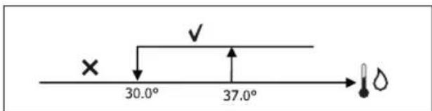
text_image
× 30.0° 37.0°text_image
On set-0,5° set Off
text_image
37.0° 39.0°text_image
On 9° 10.0° Offtext_image
Vmin Set+0.5° Set+1.5° Vmedtext_image
Inib. Set-2.0° Set-1.5°PERMISSÃO À ÁGUA
text_image
✓ 10.0° × →natural_image
Diagram of a rope knot with two connectors (no text or symbols)ALGEMENE WAARSCHUWINGEN .... 1
BELANGRIJKSTE KENMERKEN.... 2
BELANGRIJKSTE FUNCTIES 2
GEBRUIKERSTERMINAL.... 3
TOETSENBORD....3
COMBINATIES VAN ACTIEVE TOETSEN....4
DE EENHEID IN-/UITSCHAKELEN....4
TEMPERATUURSET EN VENTILATIESNELHEID WIJZIGEN ....4
ALGEMENE WAARSCHUWINGEN
activering/deactivering UURBUNDELS


| BESCHRIJVING DEFAULT | MOGELIJKE WAARDEN | |
| Unit type 3 speeds | 3 speeds4 speeds | |
| Number of pipes 2 Pipes 2 Pipes - 4 Pipes | ||
| Air probe Display Display - Board | ||
| Temperature display Celsius Celsius - Fahrenheit | ||
| Type of ventilation | Step | Step - Modulating |
| Valve configuration | Not included | Not included - On/Off - Modulating |
| Switching Summer/Winter | From keyboard/serial | From keyboard/serialFrom Digital inputAuto on water temp.Auto on air temp. |
| DOUT Configuration No use | (see dedicated paragraph) | |
| Digital output logic | N.A. | N.A. – N.C. |
| Heater included | No | No/Yes |
| Water probe installed | No | No/Yes |
| Number of water probes 4-pipe unit | 1 | 1/2 |
| Humidity probe installed | No | No/Yes |
| Turning Economy on from digital input | No | No/Yes |
| Turning ON/OFF on from digital input | No | No/Yes |
| Dehumidify from DIN | No | No/Yes |
| Ventilation in STANDBY | Standard | StandardAlways ONAlways OFF |
| Ventilation speed in standby | Low | Extra-lowLowMediumHigh |
| Natural convection | No | No/Yes |
| ON/OFF and SUM/WIN with disconnected serial | From keyboard | From keyboardFrom supervisor |
| Language | Italian | Italian/English |
| Stand-by Mode | Off | Off - Clock - Temperature |
CONFIGURATIEBEPERKINGEN
BESCHRIJVING DEFAULT
| Minimum cooling SET limit 10.0 °C | |
| Maximum cooling SET limit 35.0 °C | |
| Minimum heating SET limit 5.0 °C | |
| Maximum heating SET limit 30.0 °C | |
| Minimum humidity SET limit 35% | |
| Maximum humidity SET limit 75% | |
| Humidity hysteresis 5% | |
| Offset on humidity reading 0% | |
| Minimum value of modulating ventilation 20% | |
| Maximum value of modulating ventilation 100% | |
| Air probe offset 0.0 °C | |
| Water probe offset 0.0 °C | |
| Heating water probe offset 0.0 °C | |
| Economy Hysteresis 2.5 °C | |
| Cooling water consent SET 22.0 °C | |
| Cooling water consent hysteresis | 5.0 °C |
| Heating water consent SET 30.0 °C | |
| Heating water consent hysteresis | 7.0 °C |
| Dehumidification water consent SET | 10.0 °C |
| Dehumidification water consent hysteresis | 2.0°C |
| Valve water consent SET | 30 °C |
| Valve water consent hysteresis | 5.0 °C |
| Heater water consent SET | 39.0 °C |
| Heater water consent hysteresis | 2.0 °C |
| Temperature minimum control SET | 9.0 °C |
| Temperature minimum control hysteresis | 1.0 °C |
| Neutral zone | 5.0 °C |
| Modulating ventilation % in standby 20% 20% | |
| Default values RESET | No |
HET SET-UP MENU
text_image
17.0° 37.0°
other
| Step | Value | |---|---| | set-3°C | 3 | | set-2°C | | | set-1,5°C | 2 | | set-0.5°C | 1 | The chart displays a discrete thermal or thermal process with three distinct temperature thresholds (set-3°C, set-2°C, set-1,5°C) and an associated output symbol (*). The values for the sequence are explicitly labeled as 1, 2, and 3.AUTOMATISCHE WERKING VOOR EENHEDEN MET 4 SNELHEDEN EN MODULERENDE KLEP/KLEPPEN:
line
| Condition | Value [%] | |---|---| | set | 20 | | set+0.5°C | 20 | | set+3°C | MAX (at 20%) |VERWARMING MET CONFIGURATIES OP 3 SNELHEDEN
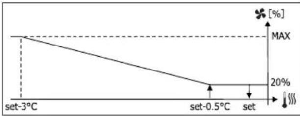
line
| Temperature | Value (%) | | :--- | :--- | | set-3°C | MAX | | set-0.5°C | 20 | | set | 20 |VERWARMING MET CONFIGURATIES OP 4 SNELHEDEN
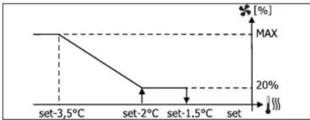
line
| Temperature | Value (%) | | :--- | :--- | | set-3.5°C | MAX | | set-2°C | 20 | | set-1.5°C | 20 | | set | 20 |
text_image
17.0° 22.0°VERWARMING
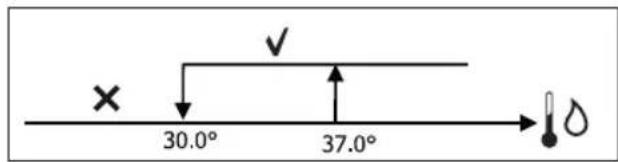
text_image
× 30.0° 37.0°line
| Condition | Value (%) | |---|---| | set-1.5°C | 100 | | set-0.5°C | 20 | | set | 20 |CONSENSUS VAN HET WATER
text_image
× 25.0° 30.0°text_image
On set-0,5° set Off
text_image
37.0° 39.0°text_image
On 9° 10.0° Offtext_image
Vmin Set+0.5° Set+1.5° Vmedtext_image
Inib. Set-2.0° Set-1.5°CONSENSUS VAN HET WATER
text_image
✓ 10.0° × →COIL STATUS (DIGITAAL LEZEN/SCHRIJVEN)
| BESCHRIJVING | |
| 1 | besturing ON/OFF |
| 2 | bediening ZOMER/WINTER |
| 3 | bediening ECONOMY |
| 4 | bediening INSCHAKELING ANTIVRIES |
| 5 | bediening INSCHAKELING ELEKTRISCHE WEERSTANDEN |
| 6 | bediening MAN/AUTO van de modulerende ventilatie |
| 7 | inschakeling ON/OFF via MASTER |
| 8 | inschakeling ECONOMY via MASTER |
| 9 | inschakeling ZOMER/WINTER via MASTER |
| 10 | inschakeling ANTIVRIES via MASTER |
| 11 | inschakeling ELEKTRISCHE WEERSTANDEN via MASTER |
| 12 | inschakeling SETPOINT via MASTER |
| 13 | inschakeling LIMIETEN VAN DE SETPOINT via MASTER |
| 14 | inschakeling VENTILATIESNELHEID via MASTER |
| 15 | bediening TOETSENBLOKKERING |
| 16 | toestemming inschakeling CONTROLE VOCHTIGHEID via MASTER |
| 17 | activering CONTROLE VOCHTIGHEID |
| 18 | bediening CONFIGUREERBARE DIGITALE UITGANG NO7 |
INPUT STATUS (DIGITAAL ALLEEN LEZEN)
natural_image
Diagram of a rope knot with two cylindrical rods (no text or symbols)| LEÍRÁS DEFAULT LEHETSÉGES ÉRTÉKEK | ||
| Unit type 3 speeds | 3 speeds4 speeds | |
| Number of pipes 2 Pipes 2 Pipes - 4 Pipes | ||
| Air probe Display Display - Board | ||
| Temperature display Celsius Celsius - Fahrenheit | ||
| Type of ventilation Step Step - Modulating | ||
| Valve configuration | Not included | Not included - On/Off - Modulating |
| Switching Summer/Winter | From keyboard/serial | From keyboard/serialFrom Digital inputAuto on water temp.Auto on air temp. |
| DOUT Configuration | No use | (see dedicated paragraph) |
| Digital output logic | N.A. | N.A. – N.C. |
| Heater included | No | No/Yes |
| Water probe installed | No | No/Yes |
| Number of water probes 4-pipe unit | 1 | 1/2 |
| Humidity probe installed | No | No/Yes |
| Turning Economy on from digital input | No | No/Yes |
| Turning ON/OFF on from digital input | No | No/Yes |
| Dehumidify from DIN | No | No/Yes |
| Ventilation in STANDBY | Standard | StandardAlways ONAlways OFF |
| Ventilation speed in standby | Low | Extra-lowLowMediumHigh |
| Natural convection No | No/Yes | |
| ON/OFF and SUM/WIN with disconnected serial | From keyboard | From keyboardFrom supervisor |
| Language | Italian | Italian/English |
| Stand-by Mode | Off | Off - Clock - Temperature |
MEGKÖTÉSEK A KONFIGURÁLÁSSAL KAPCSOLATBAN
| Minimum cooling SET limit 10.0 °C | |
| Maximum cooling SET limit 35.0 °C | |
| Minimum heating SET limit 5.0 °C | |
| Maximum heating SET limit 30.0 °C | |
| Minimum humidity SET limit 35% | |
| Maximum humidity SET limit 75% | |
| Humidity hysteresis 5% | |
| Offset on humidity reading 0% | |
| Minimum value of modulating ventilation 20% | |
| Maximum value of modulating ventilation 100% | |
| Air probe offset 0.0 °C | |
| Water probe offset 0.0 °C | |
| Heating water probe offset 0.0 °C | |
| Economy Hysteresis 2.5 °C | |
| Cooling water consent SET 22.0 °C | |
| Cooling water consent hysteresis 5.0 °C | |
| Heating water consent SET 30.0 °C | |
| Heating water consent hysteresis | 7.0 °C |
| Dehumidification water consent SET | 10.0 °C |
| Dehumidification water consent hysteresis | 2.0°C |
| Valve water consent SET | 30 °C |
| Valve water consent hysteresis | 5.0 °C |
| Heater water consent SET | 39.0 °C |
| Heater water consent hysteresis | 2.0 °C |
| Temperature minimum control SET | 9.0 °C |
| Temperature minimum control hysteresis | 1.0 °C |
| Neutral zone | 5.0 °C |
| Modulating ventilation % in standby 20% 20% | |
| Default values RESET | No |
SETUP MENÜ
text_image
17.0° 37.0°
text_image
set set+0.5°C set+1.5°C set+2°C set+3°C 1 2 3FÜTÉS
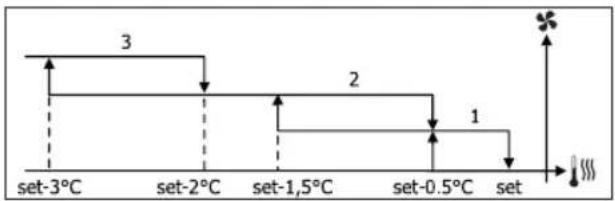
flowchart
graph TD
    A["set-3°C"] --> B["set-2°C"]
    B --> C["set-1,5°C"]
    C --> D["set-0.5°C"]
    D --> E["set"]
    style A fill:#f9f,stroke:#333
    style B fill:#f9f,stroke:#333
    style C fill:#f9f,stroke:#333
    style D fill:#f9f,stroke:#333
    style E fill:#f9f,stroke:#333
AUTOMATA MÜKÖDÉS 4 SEBESSÉGES EGYSÉGHEZ ÉS MODULÁCIÓS SZELEPHEZ/SZELEPEKHEZ:
1 Minimum SEBESSÉG
2 Közepes SEBESSÉG
3 Maximum SEBESSÉG
sm SZUPER-MINIMUM SEBESSÉG
HÜTÉS
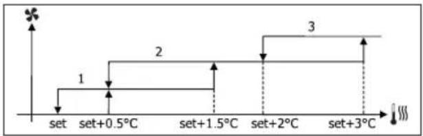
flowchart
graph TD
    A["set"] --> B["set+0.5°C"]
    B --> C["set+1.5°C"]
    C --> D["set+2°C"]
    D --> E["set+3°C"]
    style A fill:#f9f,stroke:#333
    style B fill:#ccf,stroke:#333
    style C fill:#cfc,stroke:#333
    style D fill:#fcc,stroke:#333
    style E fill:#ffc,stroke:#333
FÜTÉS
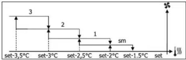
flowchart
graph TD
    A["set-3.5°C"] --> B["set-3°C"]
    B --> C["set-2.5°C"]
    C --> D["set-2°C"]
    D --> E["set-1.5°C"]
    E --> F["set"]
    style A fill:#f9f,stroke:#333
    style B fill:#f9f,stroke:#333
    style C fill:#f9f,stroke:#333
    style D fill:#f9f,stroke:#333
    style E fill:#f9f,stroke:#333
    style F fill:#f9f,stroke:#333
MODULÁCIÓS SZELLŐZÉS
line
| Condition | Value [%] | |---|---| | set | 20 | | set+0.5°C | 20 | | set+3°C | MAX (plateau) |FÜTÉS 3 SEGESSÉGES KONFIGURÁCIÓKKAL
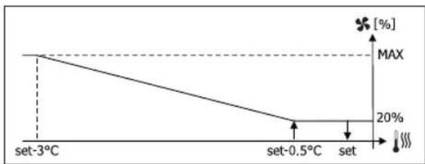
line
| Temperature | Value (%) | | :--- | :--- | | set-3°C | MAX | | set-0.5°C | 20 | | set | 20 |FÜTÉS 4 SEGESSEGES KONFIGURÁCIÓKKAL
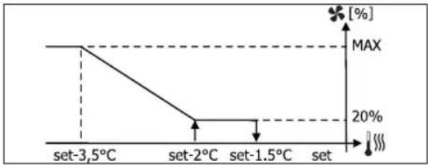
line
| Temperature | Value (%) | | :--- | :--- | | set-3,5°C | MAX | | set-2°C | 20 | | set-1.5°C | 20 | | set | MAX |
text_image
17.0° 22.0°FÜTÉS

text_image
× 30.0° 37.0°text_image
On set-0,5° Set Off setMODULÁCIÓS SZELEP
line
| Condition | Value (%) | |---|---| | set-2°C | 100 | | set-0.5°C | 20 | | set | 0 |MELEGÍTÉS 4 SEGESSÉGES KONFIGURÁCIÓKKAL

line
| Condition | Value (%) | |---|---| | set-1.5°C | 100 | | set-0.5°C | 20 | | set | 20 |ENGEDÉLY A VÍZHÓMÉRSÉKLET ALAPJÁN
text_image
× 25.0° 30.0°text_image
On set-0,5° Set Off →
text_image
37.0° 39.0° ✓ ×text_image
On 9° 10.0° Offtext_image
Vmin Set+0.5° Set+1.5° Vmedtext_image
Inib. Set-2.0° Set-1.5°ENGEDÉLY A VÍZHÖMÉRSÉKLET ALAPJÁN
text_image
✓ 10.0° × →natural_image
Simple line drawing of a rope knot with two connectors (no text or symbols)FWV, FWL, FWM, FWZ, FWR, FWS, FWD
| ОПИСАНИЕ | ПО УМОЛЧАНИЮ |
| Minimum cooling SET limit 10.0 °C | |
| Maximum cooling SET limit 35.0 °C | |
| Minimum heating SET limit 5.0 °C | |
| Maximum heating SET limit 30.0 °C | |
| Minimum humidity SET limit 35% | |
| Maximum humidity SET limit 75% | |
| Humidity hysteresis 5% | |
| Offset on humidity reading 0% | |
| Minimum value of modulating ventilation 20% | |
| Maximum value of modulating ventilation 100% | |
| Air probe offset 0.0 °C | |
| Water probe offset 0.0 °C | |
| Heating water probe offset 0.0 °C | |
| Economy Hysteresis 2.5 °C | |
| Cooling water consent SET 22.0 °C | |
| Cooling water consent hysteresis | 5.0 °C |
| Heating water consent SET 30.0 °C | |
| Heating water consent hysteresis | 7.0 °C |
| Dehumidification water consent SET | 10.0 °C |
| Dehumidification water consent hysteresis | 2.0°C |
| Valve water consent SET | 30 °C |
| Valve water consent hysteresis | 5.0 °C |
| Heater water consent SET | 39.0 °C |
| Heater water consent hysteresis | 2.0 °C |
| Temperature minimum control SET | 9.0 °C |
| Temperature minimum control hysteresis | 1.0 °C |
| Neutral zone | 5.0 °C |
| Default values RESET | No |
text_image
17.0° 37.0°
other
| Level | Value | |---|---| | set-3.5°C | 3 | | set-3°C | 2 | | set-2.5°C | 1 | | set-2°C | sm | | set-1.5°C | | | set | |line
| Condition | Value [%] | |---|---| | set | 20 | | set+0.5°C | 20 | | set+3°C | MAX (at 20%) |text_image
17.0° 22.0°ОБОГРЕВАНИЕ
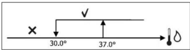
text_image
× 30.0° 37.0°text_image
On set-0,5° Off setМОДУЛИРУЮЩИЙ КЛАПАН
text_image
× 25.0° 30.0° ✓ ↑ →text_image
37.0° 39.0°text_image
On 9° 10.0° Offtext_image
Vmin Set+0.5° Set+1.5° Vmedtext_image
Inib. Set-2.0° Set-1.5°text_image
✓ 10.0° × !natural_image
Simple line drawing of a rope knot with two connectors (no text or symbols)FWV, FWL, FWM, FWZ, FWR, FWS, FWD
| ΠΕΡΙΓΡΑΦΗ DEFAULT ΠΙΘΑΝΕΣ ΤΙΜΕΣ | ||
| Unit type 3 speeds | 3 speeds4 speeds | |
| Number of pipes 2 Pipes 2 Pipes - 4 Pipes | ||
| Air probe Display Display - Board | ||
| Temperature display Celsius Celsius - Fahrenheit | ||
| Type of ventilation Step | Step - Modulating | |
| Valve configuration | Not included | Not included - On/Off - Modulating |
| Switching Summer/Winter | From keyboard/serial | From keyboard/serialFrom Digital inputAuto on water temp.Auto on air temp. |
| DOUT Configuration | No use | (see dedicated paragraph) |
| Digital output logic N.A. | N.A. - N.C. | |
| Heater included | No | No/Yes |
| Water probe installed | No | No/Yes |
| Number of water probes 4-pipe unit | 1 | 1/2 |
| Humidity probe installed | No | No/Yes |
| Turning Economy on from digital input | No | No/Yes |
| Turning ON/OFF on from digital input | No | No/Yes |
| Dehumidify from DIN | No | No/Yes |
| Ventilation in STANDBY | Standard | StandardAlways ONAlways OFF |
| Ventilation speed in standby | Low | Extra-lowLowMediumHigh |
| Natural convection No | No/Yes | |
| ON/OFF and SUM/WIN with disconnected serial | From keyboard | From keyboardFrom supervisor |
| Language | Italian | Italian/English |
| Stand-by Mode | Off | Off - Clock - Temperature |
| Minimum cooling SET limit 10.0 °C | |
| Maximum cooling SET limit 35.0 °C | |
| Minimum heating SET limit 5.0 °C | |
| Maximum heating SET limit 30.0 °C | |
| Minimum humidity SET limit 35% | |
| Maximum humidity SET limit 75% | |
| Humidity hysteresis 5% | |
| Offset on humidity reading 0% | |
| Minimum value of modulating ventilation 20% | |
| Maximum value of modulating ventilation 100% | |
| Air probe offset 0.0 °C | |
| Water probe offset 0.0 °C | |
| Heating water probe offset 0.0 °C | |
| Economy Hysteresis 2.5 °C | |
| Cooling water consent SET 22.0 °C | |
| Cooling water consent hysteresis 5.0 °C | |
| Heating water consent SET 30.0 °C | |
| Heating water consent hysteresis | 7.0 °C |
| Dehumidification water consent SET | 10.0 °C |
| Dehumidification water consent hysteresis | 2.0°C |
| Valve water consent SET | 30 °C |
| Valve water consent hysteresis | 5.0 °C |
| Heater water consent SET | 39.0 °C |
| Heater water consent hysteresis | 2.0 °C |
| Temperature minimum control SET | 9.0 °C |
| Temperature minimum control hysteresis | 1.0 °C |
| Neutral zone | 5.0 °C |
| Modulating ventilation % in standby 20% 20% | |
| Default values RESET | No |
TO MENOY SETUP
text_image
17.0° 37.0°
line
| Condition | Value [%] (%) | |---|---| | set | 20 | | set+0.5°C | 20 | | set+3°C | MAX |text_image
17.0° 22.0° ×ΘΕΡΜΑΝΣΗ
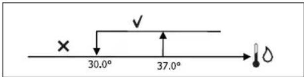
text_image
× 30.0° 37.0°text_image
On set-0,5° Set Off setΒΑΛΒΙΔΑ ΔΙΑΜΟΡΦΩΣΗΣ
text_image
× 25.0° 30.0°text_image
37.0° 39.0° ✓ ×text_image
On 9° 10.0° Offtext_image
Vmin Set+0.5° Set+1.5° Vmedtext_image
Inib. Set-2.0° Set-1.5°ΣΥΝΑΙΝΕΣΗ ΝΕΡΟΥ
text_image
✓ 10.0° × →natural_image
Simple line drawing of a rope knot with two connectors (no text or symbols)FWV, FWL, FWM, FWZ, FWR, FWS, FWD
natural_image
Technical line drawing of a mechanical device with internal components and directional arrows indicating movement (no text or symbols)12
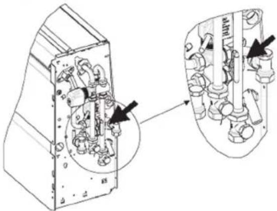
natural_image
Technical line drawing of a mechanical assembly with internal components and directional arrows (no text or symbols)13
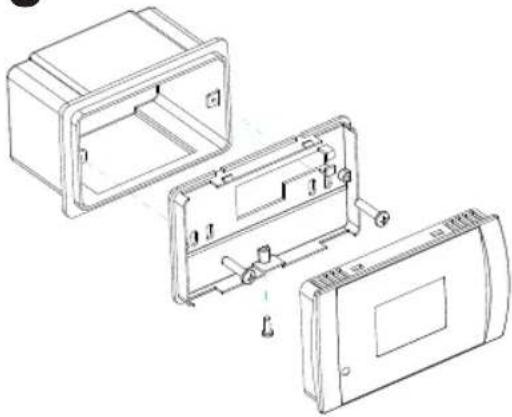
natural_image
Technical line drawing of a device housing with internal components and mounting holes (no text or symbols)14
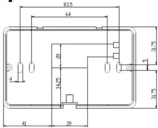
text_image
83.5 64 20 34.25 41 30 31.75 5 31.7515
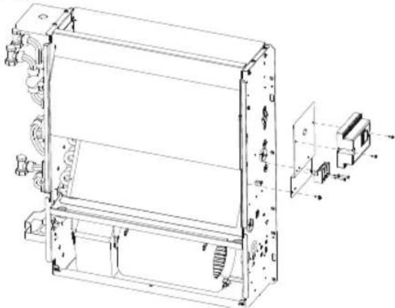
natural_image
Technical line drawing of a mechanical assembly with mounting brackets and internal components (no text or symbols)16
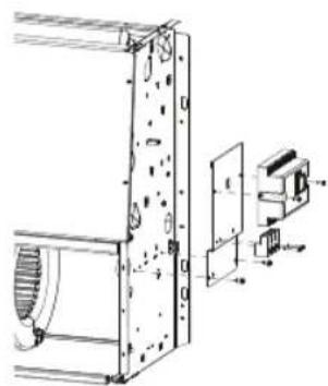
natural_image
Technical line drawing of a mechanical assembly with no visible text or symbols17 18
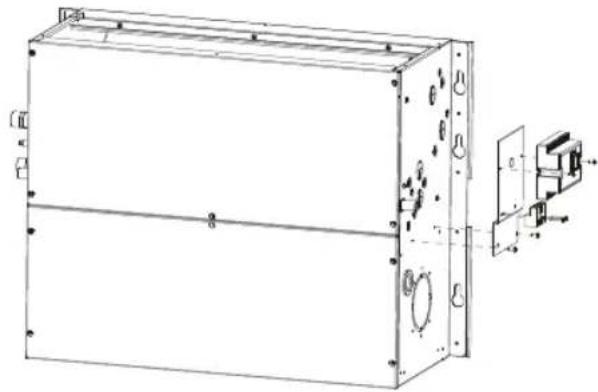
natural_image
Technical line drawing of a rectangular electronic device with mounting holes and internal components (no text or symbols)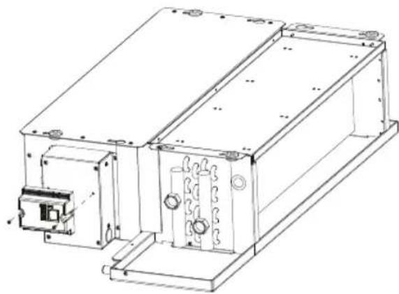
natural_image
Technical line drawing of an electronic device housing with mounting brackets and internal components (no text or symbols)19
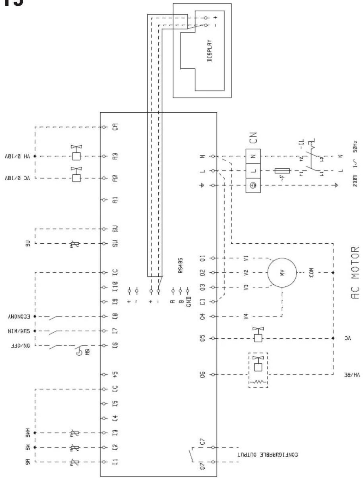
text_image
15 DISPLAY CA VA B/10V VC B/10V SU IC RS485 B GND ECONOMY SUN/MIN ON/OFF MS I9 I10 + - - - R C1 03 02 01 V3 V2 V4 COM AC MOTOR L N CN - F r1 IL v1 L2 L N 238V 1~ 50Hz VH/RE VC CONFLURABLE OUTPUT 071 C7 I1 I2 I3 I4 I5 IC +5 SNS RS19
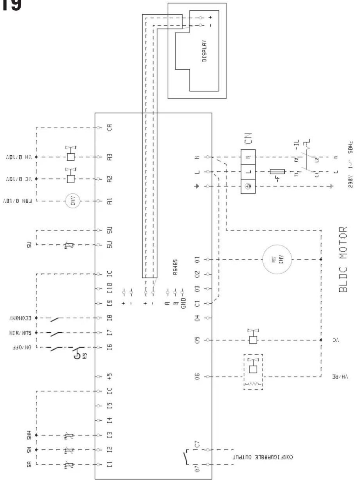
text_image
19 DISPLAY ADL/O HA AC AC/DV AB1/0BV FRH 0/1BV SU SU IC IC C9 I10 C18 C17 IC +5 I6 I7 ON/OFF ECONOMY SUN/CHN SR SH SNH I1 I2 I3 I4 I5 07 I C7 RS485 CN L N L L CN - F r2 IL L2 L L 230V 1~ 50Hz HV HV BLDC MOTOR HV/RE CA Coolflicurable outputNOTE


FWECSA

NOTE


NOTE


FWECSA

NOTE


DAIKIN

natural_image
Abstract geometric shape with diagonal division between black and gray triangular sections (no text or symbols)Stampato su carta riciclata
Printed on recycled paper