
Sani 600 Mirror WiFi - Heating Eurom - Free user manual and instructions
Find the device manual for free Sani 600 Mirror WiFi Eurom in PDF.

| Brand | Eurom |
| Model | Sani 600 Mirror WiFi |
| Product type | Electric wall heater |
| Dimensions (W x H x D) | 80 x 60 x 5 cm |
| Weight | 11.2 kg |
| Power | 600 W |
| Voltage | 220-240 V ~ 50 Hz |
| Protection rating | IP24 |
| Protection class | Class I |
| Connectivity | Wi-Fi, Eurom Smart app |
| Main functions | Heating, adjustable thermostat (0-37°C), timer (0-24h), weekly programming via app |
| Material | Metal, mirror glass |
| Installation | Wall mounting, bathroom zone 3 |
| Safety | Overheat protection, automatic shut-off, do not cover |
| Care and cleaning | Wipe with a damp cloth after cooling, do not immerse |
| Warranty | 60 months |
| Included accessories | Wall bracket, plugs, screws, manual |
Frequently Asked Questions - Sani 600 Mirror WiFi Eurom
User questions about Sani 600 Mirror WiFi Eurom
0 question about this device. Answer the ones you know or ask your own.
Ask a new question about this device
Download the instructions for your Heating in PDF format for free! Find your manual Sani 600 Mirror WiFi - Eurom and take your electronic device back in hand. On this page are published all the documents necessary for the use of your device. Sani 600 Mirror WiFi by Eurom.
USER MANUAL Sani 600 Mirror WiFi Eurom
natural_image
Blank white image with no visible content, text, or symbols| Model: | Product code: |
| Sani Mirror 400 Wi-Fi | 350418 |
| Sani Mirror 400 Wi-Fi (Swiss plug) | 350425 |
| Sani Mirror 600 Wi-Fi | 350432 |
| Sani Mirror 600 Wi-Fi (Swiss plug) | 350449 |
Afbeelding 3
Afbeelding 7

Afbeelding 8
Afbeelding 9
Installatie

WAARSCHUWING
Afbeelding 10
Werking

WAARSCHUWING
Afbeelding 11
De afteltimer instellen
Afbeelding 12
Slimme timer
Thank you for choosing this EUROM device. You have purchased a quality device that you will enjoy for many years. Using this device with respect and care will reduce the risk of personal injury or material damage.

CAUTION
It is important to read and understand this instruction manual before installing and using the device.
Introduction
This manual describes the correct and safe use of this device. Keep this manual for future reference. The manual is an essential part of the device and must be given to the new owner upon resale or exchange. This manual has been compiled with the utmost care. Nevertheless, we reserve the right to improve and adjust this manual at any time. The images used may differ.
The following symbols and terms are used in this manual to alert the reader on safety issues and important information:

WARNING
Indicates a hazardous situation which, if the safety instructions are not followed, can lead to injuries to the operator or bystanders, light and/or moderate damage to the product or to the environment.

CAUTION
Indicates a hazardous situation which, if the safety instructions are not followed, can lead to light and/or moderate damage to the product or to the environment.
Warranty
EUROM offers a 60-month warranty on this device from the date of purchase. The warranty does not cover wear and tear from normal use. The warranty expires if a defect is the result of unintentional or careless use of the device. The manufacturer, importer and supplier are not liable for incorrect connections.
Identification
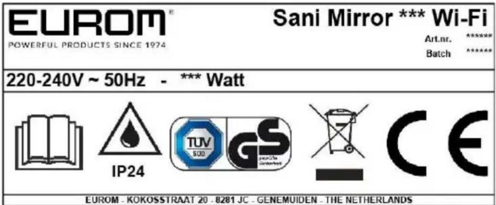
Figure 1
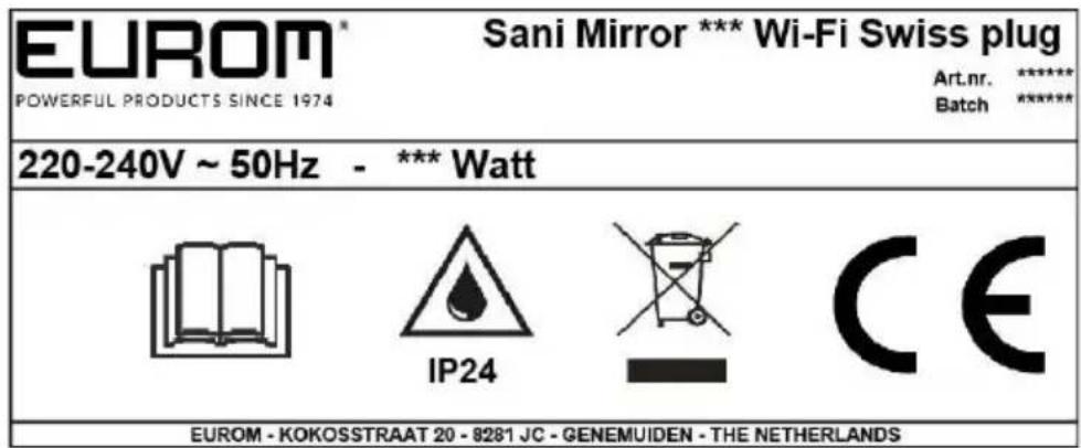
Figure 2
Specifications
| Type: | Sani Mirror 400 Wi-Fi | Sani Mirror 600 Wi-Fi |
| Product size: | 5 x 50 x 70 cm | 5 x 80 x 60 cm |
| Weight: | 8.2 kg | 11.2 kg |
| Voltage: | 220 -240 V / 50 Hz | 220 -240 V / 50 Hz |
| Power: | 400 W | 600 W |
| Protection rating: | IP24 | IP24 |
| Protective class: | Class I | Class I |
Description
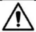
The Sani Mirror Wi-Fi (Figure 3) is an easy-to-use electric bathroom heater for use in zone 3 of the bathroom (Figure 5). The Sani Wi-Fi can be used with the Eurom Smart App.
- Main device
- ON/OFF switch
- Control panel and LED display
- Power plug
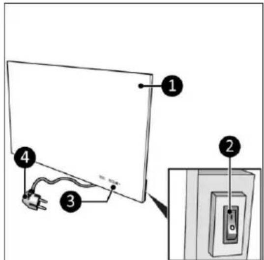
Figure 3
Control panel and display
-
Wi-Fi indication
-
Timer button
-
Minus button
-
Plus button
-
Temperature indication
The LED-screen will extinguish automatically after ± 15 seconds. Touch one of the buttons to light it up again.
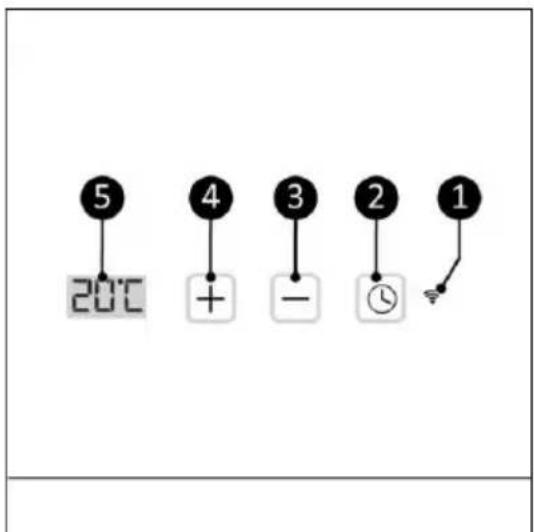
Figure 4
Safety
Please read and understand these safety instructions. Incorrect use can cause injury and will void EUROM's warranty.
This device is not suitable for use by persons with a physical, sensory or mental disability, or lack of experience and knowledge (including children). Keep the device out of reach of children, unqualified persons and pets. Never leave the device unattended while it is in operation.
The device is equipped with an overheating protection, which switches it off automatically in case of internal overheating. Switch the device off, unplug the power plug, remove the source of overheating, let it cool down and use as normal. Do not use the device if the source of overheating cannot be traced or if the problem persists, but always contact your supplier.
This device is save to use in the bathroom when the device is mounted:
- in zone 3 of a toilet room or bathroom with a bath, shower with screen and shower without screen (Figure 5);
- in a fixed position;
- out of reach for operation by a person in a bath or shower.
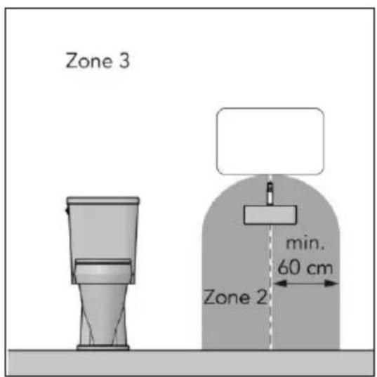
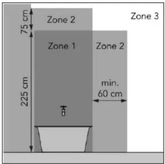
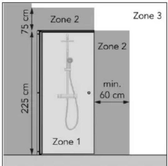
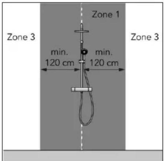
Figure 5
General safety instructions

WARNING
- Prevent splashing water on or in the device.
- Do not immerse any part of the device in water or other liquids.
• Never insert fingers or other objects into the openings of the device.
• Do not expose the device to strong vibrations or mechanical stress.
WARNING
The device becomes very hot during use. Do not touch the device during use or within five minutes after use.
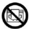
CAUTION
Do not cover the device, during usage or after use while the device is still hot. To reduce the risk of fire, keep textiles, curtains, tent canvasses and other flammable material at a minimum distance of 1 meter from the device.
Safety during operation

WARNING
Do not use the device:
• outdoors or in a small space ( < 7 m^3 );
- lying, leaning or standing;
- if any parts are dirty or wet;
- near large objects, like behind a door, under a shelf or cupboard;
• near a water source, like a bath, shower, swimming pool or open window;
• near or in a dusty and dirty environment, like a construction site;
- near flammable materials, liquids or fumes, like a shed, stable or green house;
- near other heat sources and open fire;
- near, under or facing a socket outlet;
- with an appliance that automatically switches the device on, such as a timer, dimmer or any other device.
If the device, the electric cable or plug shows damage or is malfunctioning, immediately take the appliance out of use and disconnect the power supply.
Transport and storage
- Clean the device before storing it.
- Transport the device upright.
- Store the device upright in its original packaging in a cool, dry and dust-free area.
Installation
The device is packed in one box. Remove all packaging material and check that the device is not damaged. Do not use the device if it is damaged, but always contact your supplier. Keep the packaging for safe storage and transport.
Wall mounting
WARNING
The wall used for mounting must be made from non-flammable material and should be able to withstand a minimum temperature of 125^ C.

CAUTION
Make sure to use suitable fastening materials, depending on the surface. Never block the space between the device and the wall.
- Place the device on a non-flammable and solid wall.
-
Place the device with a minimum distance (Figure 6) of:
-
50 cm from the ceiling;
• 20 cm from the side walls; - 10 cm from the floor;
-
50 cm clearance on the front side.
-
Do not mount the device:
-
immediately below a socket outlet;
-
on a ceiling or roof.
-
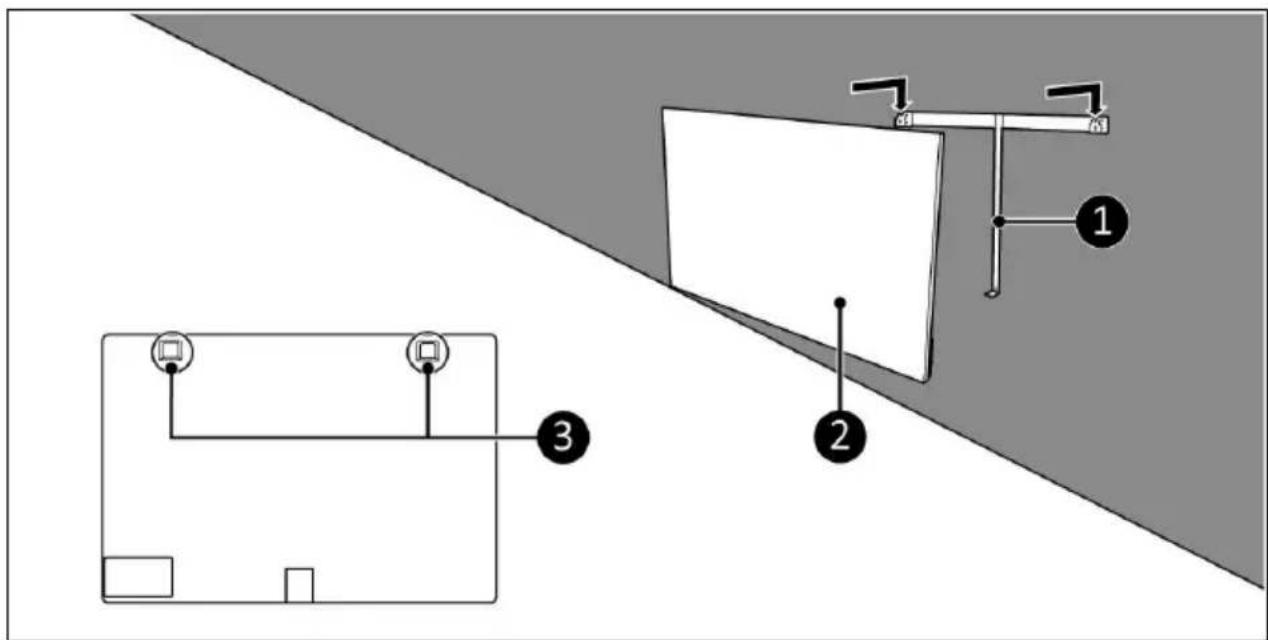
Place the wall bracket (Figure 7, pos. 1) against the wall and mark the five holes.
- Drill five holes at the marked spots.
- Place plugs (Figure 7, pos. 3).
- Screw and tighten the wall bracket to the wall with five large screws (Figure 7, pos. 2) using a Phillips screwdriver (Figure 7, pos.4).
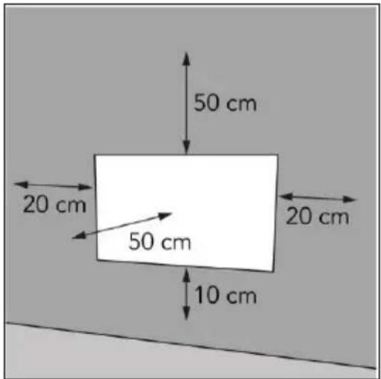
Figure 6
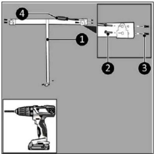
Figure 7

Figure 8
-
Place the device brackets (Figure 8, pos. 3) over the wall bracket (Figure 8, pos. 1).
-
Slide the device (Figure 8, pos. 2) into the openings of the wall bracket.
-
Screw and tighten the device (Figure 9, pos. 1) with a small screw (Figure 9, pos. 3) to the wall bracket using a Phillips screwdriver (Figure 9, pos. 2).
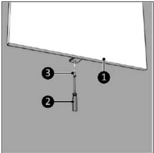
Figure 9
Installation
WARNING
Do not put the power plug into the wall socket before the device is correctly mounted.
Do not use an extension cable; this can cause overheating and fire. If using an extension cable is unavoidable, make sure it is undamaged and earthed. Use an extension cable with a minimum power of 800 Watt. Always unwind the extension cable completely to prevent overheating.

CAUTION
Make sure that the main voltage is the same as indicated on the identification label of the device. All electrical connections must stay dry under all circumstances.
- Make sure the device is correctly mounted.
- Make sure the ON/OFF switch is in the OFF position (Figure 10, pos. 2).
- Place the power plug (Figure 10, pos. 1) into an earthed wall socket that is easily accessible. Use an earthed wall socket with a minimum power of 800 Watt.
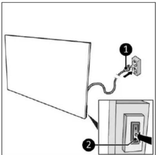
Figure 10
Operation

WARNING
Before every use, make sure that:
- you operate the device with dry hands;
• the device is clean and dry;
• the device is not damaged; - the device is not covered or blocked;
- the device is securely mounted.

CAUTION
When the device is turned on or off, it may emit a sound. This is material expanding and shrinking during heating and cool-down.
- Set the ON/OFF switch to the ON position (Figure 11, pos. 1).
- The control panel and display (Figure 11, pos. 2) will light up.
- Press the Plus or Minus button to set the desired temperature, from 0 °C to 37 °C. The device starts heating when the set temperature is higher then the ambient temperature.
- The display will first show the set temperature for 3 seconds followed by the ambient temperature.
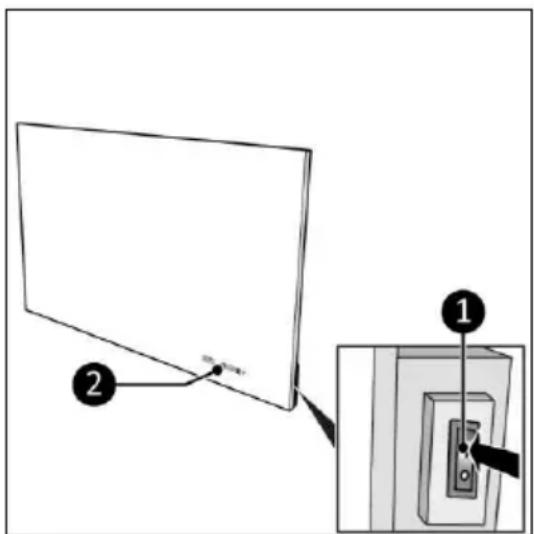
Figure 11
Set the countdown timer
- Press the Timer button once or multiple times to set the countdown timer, from 00 to 24 in whole hours.
Eurom Smart App
The device can be operated using an app on a smartphone or tablet. The Eurom Smart app can be used to:
- switch the device on and off (without anticipation);
• regulate the temperature; -
set on and off timer settings daily, on the weekly timer.
-
Open the Eurom Smart App manual with the QR code (Figure 12) or go to www.eurom.nl/nl/manuals.
- Complete the Eurom Smart App manual.
- When the device is connected with Wi-Fi, the Wi-Fi symbol appears on the screen.
- If the Wi-Fi symbol is blinking there is no connection.

Figure 12
Smart Timer
-
Create a schedule with days and times in the Eurom Smart app. Timer settings set in the app:
-
will be stored on the device;
- will not be visible on the device;
- will remain available if Wi-Fi disconnects;
- will remain available if the device is switched off or unplugged;
- can only be removed via the app.
- Check the data in the app regularly.
Reset Wi-Fi connection
- Press and hold the Timer button until the Wi-Fi symbol starts blinking alternating fast and slow. Existing connections will be deleted and a new connection can be made.
Switch off Wi-Fi connection
- Press and hold the Minus button until a short beep sounds. The Wi-Fi is switched off and the Wi-Fi symbol will disappear from the screen.
- Press and hold the Minus button until a short beep sounds. The Wi-Fi is switched on and the Wi-Fi symbol will appear on the screen.
After operation

CAUTION
Do not use the power cable to unplug or carry the device. Do not wind the power cable too tightly or in sharp corners. Do not wrap the power cable around the device.
- Make sure the ON/OFF switch is in the OFF position (Figure 10, pos. 2).
- Disconnect the power plug from the power outlet (Figure 10).
- Let the device cool down before touching it.
- Wind the power cable.
Maintenance
WARNING
Do not perform any repairs or modifications to this device.
Maintenance and repairs must be carried out by a EUROM authorized professional. If the electric cable and/or electric plug is damaged, it should be replaced by the manufacturer or its service employee or persons with similar qualifications to prevent risks.
Cleaning
WARNING
The device becomes very hot. Make sure the device is turned off, unplugged and completely cooled down.

CAUTION
Do not use:
- scouring pads;
- hard brushes;
- flammable, aggressive or chemical cleaning products.
Prevent water from entering the device. Do not immerse any part of the device in water or other liquids.
It is recommended to clean the device after each use and prior to storage.
- Wipe the device with a damp, clean, soft, lint-free cloth or a soft brush.
- Let the device dry completely prior to use and storage.
Disposal

At its end of life, discard the device according to the local laws and regulations, or deliver the device to your supplier.
| Information requirement for the electric local space heaters | |||||
| Model identifier(s): Sani Mirror 400 Wi-Fi | |||||
| Item | Symbol | Value | Unit | Item | Unit |
| Heat output | Type of heat input, for electric storage local space heaters only (select one) | ||||
| Nominal heat output | Pnom | 0,4 | kW | manual heat charge control, with integrated thermostat | No |
| Minimum heat output (indicative) | Pmin | 0 | kW | manual heat charge control with room and/or outdoor temperature feedback | No |
| Maximum continuous heat output | Pmax,c | 0,4 | kW | electronic heat charge control with room and/or outdoor temperature feedback | No |
| Auxiliary electricity consumption | fan assisted heat output | No | |||
| At nominal heat output | elmax | 0,4 | kW | Type of heat output/room temperature control (select one) | |
| At minimum heat output | elmin | 0 | kW | single stage heat output and no room temperature control | No |
| In standby mode | eISB | 0,001 | kW | Two or more manual stages, no room temperature control | No |
| with mechanic thermostat room temperature control | No | ||||
| Model identifier(s): Sani Mirror 600 Wi-Fi | with electronic room temperature control | No | |||
| Item | Symbol | Value | Unit | electronic room temperature control plus day timer | No |
| Heat output | electronic room temperature control plus week timer | Yes | |||
| Nominal heat output | Pnom | 0,6 | kW | Other control options (multiple selections possible) | |
| Minimum heat output (indicative) | Pmin | 0 | kW | room temperature control, with presence detection | No |
| Maximum continuous heat output | Pmax,c | 0,6 | kW | room temperature control, with open window detection | No |
| Auxiliary electricity consumption | with distance control option | Yes | |||
| At nominal heat output | elmax | 0,6 | kW | with adaptive start control | No |
| At minimum heat output | elmin | 0 | kW | with working time limitation | No |
| In standby mode | eISB | 0,001 | kW | with black bulb sensor | No |
| Contact details | Eurom - Kokosstraat 20 - 8281 JC - Genemuiden - The Netherlands | ||||
Abbildung 3
Abbildung 7
Abbildung 8
Abbildung 9
Installation

WARNUNG
Abbildung 10
Betrieb

WARNUNG
Abbildung 11
Abbildung 12
Intelligenter Timer
Figure 3
Figure 7

Figure 8
Figure 9
Installation
AVERTISSEMENT
Figure 10
Utilisation

AVERTISSEMENT
Figure 11
Figure 12
Minuterie intelligente
Figur 3
Figur 7
Figur 8
Figur 9
Installation
WARNING
Figur 10
Drift

WARNING
Figur 11
Figur 12
Smart timer
Figur 3
Kontrolpanel og display
- Indikator for Wi-Fi
- Timerknap
- Minusknap
- Plusknap
- Indikator for temperatur
Figur 7

Figur 8
Figur 9
Installation
ADVARSEL
Figur 10
Betjening

ADVARSEL
Figur 11
Figur 12
Smart Timer
Obrázek 3
Obrázek 7

Obrázek 8
Obrázek 9
Instalace

VAROVÁNÍ
Obrázek 10
Provoz
VAROVÁNÍ
Obrázek 11
Obrázek 12
Chytrý časovač
Obrázok 3
Obrázok 7

Obrázok 8
Obrázok 9
Inštalácia

VÝSTRAHA
Obrázok 10
Prevádzka

VÝSTRAHA
Obrázok 11
Obrázok 12
Figura 3
Figura 7

Figura 8
Figura 9
Instalare

AVERTISMENT
Figura 10
Functionare

AVERTISMENT
Figura 11
Figura 12