
Verso - Wheelchair Vermeiren - Free user manual and instructions
Find the device manual for free Verso Vermeiren in PDF.

| Product type | Class A electric wheelchair |
| Brand | Vermeiren |
| Model | Verso |
| Maximum user weight | 130 kg |
| Dimensions (L x W x H) | 1078 mm x 560-670 mm x 937-1002 mm (depending on seat width) |
| Total weight | 31.3 kg (without tilted backrest) / 35 kg (with 30° backrest) |
| Battery | 12.8 Ah or 17.5 Ah, lithium or lead-acid (depending on version) |
| Range | 15 km (12.8 Ah) / 21 km (17.5 Ah) under optimal conditions |
| Maximum speed | 6 km/h |
| Nominal slope | 10° |
| Obstacle clearance | 15 mm |
| Turning diameter | 1145 mm |
| Ground clearance | 61 mm |
| Tires | Front wheels 200x50 mm, rear wheels 12"; max. pressure 2.5 bar (pneumatic tires) |
| Motors | 2 direct drive motors of 250 W each |
| Intended use | Indoor and outdoor, for transporting a person with reduced mobility (max weight 130 kg) |
| Maintenance | Visual inspection before each use; annual maintenance by authorized dealer; cleaning with damp cloth and mild soap |
| Warranty | Warranty according to general terms of the country; subject to normal use and maintenance |
| Safety | Electromagnetic brakes, anti-tip, safety belt, optional lights, console lock |
| Spare parts | Use only original Vermeiren parts |
| Recycling | Dispose of according to local regulations; dismantle to facilitate recycling |
Frequently Asked Questions - Verso Vermeiren
User questions about Verso Vermeiren
0 question about this device. Answer the ones you know or ask your own.
Ask a new question about this device
Download the instructions for your Wheelchair in PDF format for free! Find your manual Verso - Vermeiren and take your electronic device back in hand. On this page are published all the documents necessary for the use of your device. Verso by Vermeiren.
USER MANUAL Verso Vermeiren
natural_image
Exterior view of a modern electric wheelchair with black seat, white frame, and orange feet (no signage or text visible)Contents
Preface
4
1. Your product 6
1.1. Options 7
2. Before use 7
2.1. Intended use 7
2.2. General safety instructions 8
2.3. Symbols on the wheelchair 9
2.4. Transport 10
2.5. Assembly/Disassembly 15
2.6. First use and storage 17
3. Using your wheelchair 17
3.1. First ride 18
3.2. Driving outdoors 19
3.3. Operating console 21
3.4. Operating the lights (optional) 23
3.5. Brake and free-wheel lever 24
3.6. Transfer to/from the wheelchair. 25
3.7. Comfort adjustments 26
3.8. Battery status and charging 30
4. Maintenance 34
4.1. Points of maintenance 34
4.2. Maintenance instructions 36
4.3. Expected lifespan 37
4.4. Reuse 37
4.5. End of use 37
4.6. Warranty 37
5. Troubleshooting 38
6. Technical specifications 40
Preface
Congratulations! You are now owner of a Vermeiren wheelchair!
This wheelchair is made by qualified and committed personnel. It is designed and produced according to high quality standards, guarded by Vermeiren.
Thank you for your trust in the products of Vermeiren. To support you on the use of this wheelchair and its operating functions, this manual is offered. Please read this manual carefully; it will help you to get familiar with the operation, capabilities and limitations of your wheelchair.
If you still have questions after reading this manual, do not hesitate to contact your specialist dealer. He/she will be glad to help you.
Important note
To ensure your safety, and to prolong the lifetime of your product, please take good care of it and have it checked and serviced on a regular basis.
This manual reflects the latest product developments. Vermeiren has the right to implement changes to this type of product without any obligation to adapt or replace similar products previously delivered.
Pictures of the product are used to clarify the instructions. Details of the depicted product may deviate from your product.
Information available
On our website http://www.vermeiren.com/ you will always find the most recent version of the following information. Please consult this website regularly for possible updates.
Visually impaired people can download the electronic version of this manual and have it read out by means of a text-to-speech software application.
 | User manualFor user and specialist dealer |
 | Installation instructionsFor specialist dealer |
 | Service manual for wheelchairsFor specialist dealer |
 | EC declaration of conformity |
1. Your product
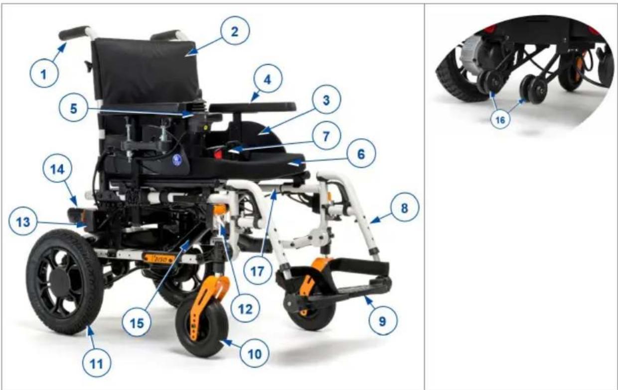
- Handgrips
- Backrest
- Armrests
- Arm pads
- Operating console
- Seat
- Safety belt
- Leg rests or footrests
- Footplates
- Steering wheels (front wheels)
- Driving wheels with motors / Rear wheels
- Front light (optional)
- Rear light (optional)
- Battery
- Cross
- Anti-tipping / Tipping aid
- Identification plate
1.1. Options
Contact your specialist dealer about options. He will gladly advise you.
2. Before use
2.1. Intended use
In this paragraph a brief description of the intended use of your product is given. Additionally, relevant warnings are added to the instructions in the other paragraphs. In this way we would like to make you aware of the possible misuse that may appear.
• This product is a medical device.
- Indications and contraindications: This wheelchair can be operated by the user sitting in the wheelchair, or it can be pushed by an attendant. The wheelchair is designed and produced to be a transport aid for users who suffer from paralysis, loss of limbs or limb deformations/defects, heart insufficiencies, ... You should NOT use this wheelchair without attendant if you suffer from physical or mental impairments that may put you, or other people, in danger when driving the wheelchair. For this reason, consult your doctor first and make sure that your specialist dealer is informed about his advice.
- This wheelchair is suitable for indoor and outdoor use.
- This wheelchair is designed and produced solely to transport/transfer one (1) person with a maximum weight of 130kg. It is not designed for transportation of goods or objects, nor for any use other than previously described.
- Only use accessories and spare parts approved by Vermeiren.
- Please read all technical details and limits of your wheelchair in chapter 6..
- The warranty on this product is based on normal use and maintenance as described in this manual. Damage to your product caused by improper use or lack of maintenance will cause the warranty to lapse.
2.2. General safety instructions
CAUTION
Risk of injuries and/or damage
- Carefully read and follow the instructions in this manual. Otherwise you may get injured or your wheelchair may get damaged.
Keep the following general warnings in mind during use:
- Do not use your wheelchair if you are under influence of alcohol, medicines or other substances that may influence your driving abilities.
- Be aware that some parts of your wheelchair may get very hot or cold due to ambient temperature, solar radiation, heating devices or due to the motor drive during the ride. Be careful when touching. Wear protective clothing if the weather is cold. After a ride, wait until the wheelchair/motor has cooled down.
- Before switching the wheelchair on, be aware of the environment/situation in which you are located. Adjust your speed to this before driving off. We advise you to use the slowest speed setting to drive indoors. For outdoor driving you can adjust the speed to a suitable speed at which you feel comfortable and safe.
- ALWAYS keep in mind that your wheelchair may stop suddenly due to a discharged battery or a protection that prevents your wheelchair from further damage. Also check the possible causes mentioned in § 5.. Use your safety belt to prevent injuries.
- Your wheelchair has been tested for electromagnetic compatibility and complies with the standard, see chapter 6.. Nevertheless, sources of electromagnetic fields may influence the driving performance of your wheelchair, such as the fields of mobile phones, power generators or high-power energy sources. On the other hand, the electronics of your wheelchair can affect other electronic appliances too, such as alarm systems of shops and automatic doors. We therefore advise you to check your wheelchair regularly for damage and wear, since these may enlarge the interference (see also chapter 4.).
- Only drive on flat surfaces where both driving wheels touch the ground and where there is sufficient contact to operate the wheelchair safely.
• Alterations or substitutions should not be made to the wheelchair securement points or to structural and frame parts or components without consulting the wheelchair manufacturer.
- Make sure that your hands, clothes, belts, buckles or jewellery don't get caught by wheels or other moving parts during use.
Be aware that your wheelchair may interfere with some types of anti-theft systems, depending on the settings used. This may cause the shop's alarm to go off.
Any serious incident [MDR (EU) 2017/745 §2 (65)] that has occurred in relation to the device should be reported to the manufacturer and the competent authority of the Member State in which the user and/or patient is established.
2.3. Symbols on the wheelchair
 | Maximum weight of the user in kg |
 | Maximum safe slope in ° (degrees). |
 | For indoor use only (battery charger) |
 | Maximum speed |
 | Type designation |
 | Catalogue number |
 | Serial number |
 | Medical device |
 | Manufacturer |
 | Date of manufacture |
 | Declaration of conformity |
 | Attention: important information |
 | It is advised to read the manual |
 | Risk of entrapment |
 | For electric devices only: Protection class II |
 | For electric devices only: Do not dispose of parts in household waste! Submit for proper recycling. |
2.4. Transport
CAUTION
Risk of damage
• Take action to protect the wheelchair from being damaged during transport.
2.4.1. Moving out of the way
Use the operating console to drive the wheelchair to its destination.
Otherwise, put the wheelchair in free-wheel mode (see §3.5.) and use the push bar to move it.
2.4.2. Transport by aircraft
EN
When transporting the wheelchair by aircraft, lock and disconnect the battery before handing the wheelchair over to airport personnel (see §3.8.2. and §3.8.3.). The battery can remain in the wheelchair. Consult your airline for the correct handling procedure.
natural_image
Close-up of a black motorcycle rear bumper with red circles highlighting mechanical components (no readable text or symbols)2.4.3. Transport by vehicle, as luggage
WARNING
Risk of injuries and damage
- Make sure that the free-wheel lever is in braking position during transport, see § 3.5..
You can drive your powered wheelchair in the car using ramps, or you can put the wheelchair in neutral mode and push it in the car using ramps. It is also possible to disassemble the wheelchair for transport (see §2.5.).
- As the wheelchair user, transfer to a car seat, see §3.6..
- Remove all moveable parts prior to transport (footrests, arm supports, etc.).
- Store moveable parts safely behind the passenger seat or in the luggage compartment.
- Drive or push the electric wheelchair in the car using ramps, or lift the parts of the disassembled wheelchair in the car.
- Attach the solid parts of the frame securely to the vehicle.
- Place the wheelchair in drive mode (engaging the parking brakes) and check that the operating console is switched off.
2.4.4. Transport by vehicle, as seat for the user
WARNING
Risk of injuries
- The wheelchair has passed the crash test of ISO 7176-19: 2022 and, as such, has been designed and tested for use only as forward-facing seat in a motor vehicle.
- The wheelchair's pelvic belt alone is not suited as an occupant restraint belt.
- Use the wheelchair's pelvic belt and the applicable three-points belt in the vehicle to prevent head and chest impacts with the vehicle.
- Do not use postural supports to restrain the user in the vehicle unless they are labelled as being in accordance with the requirements specified in ISO 7176-19:2022.
- Following involvement in any type of vehicle collision, have your wheelchair inspected by the specialist dealer or manufacturer's representative before reuse.
The wheelchair is tested using the four-point strap-tie system and a 3-point occupant-restraint system.
Whenever feasible, use the seat of the vehicle and store the wheelchair in the cargo area.
2.4.4.1. Steps to secure the wheelchair in a motor vehicle:
- Check that the vehicle is equipped with a suitable wheelchair tie down and occupant-restraint system, conform ISO 10542.
- Check that the components of the wheelchair tie down and occupant restraint system are not frayed, contaminated, damaged or broken.
- If equipped with an adjustable seat and/or back tilt, make sure that the wheelchair user is sitting as upright as possible. If the user's condition prevents this, a risk assessment should be done to evaluate the user's safety during transit.
- Remove all mounted accessories such as trays and respiratory equipment, and secure them in a safe place.
-
Position the wheelchair facing forward in the travelling direction, centrally between the tie-down rails mounted in the floor of the vehicle.
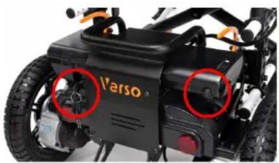
-
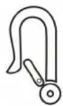
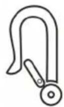
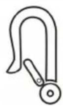
Mount the front securement straps according to the instructions of the strap-system manufacturer at the indicated place (figure 1). This place is marked on the wheelchair with a symbol (figure 2).
- Roll back the wheelchair until the front straps are tight.
- Apply the wheelchair brake.
- Mount the back securement straps according to the instructions of the strap-system manufacturer at the indicated place (figure 1). This place is marked on the wheelchair with a symbol (figure 2).
natural_image
Technical line drawing of a wheeled bicycle with articulated limbs and wheel (no text or symbols)Figure 1
Figure 2
2.4.4.2. Steps to secure the wheelchair user:
- Remove both armrests.
- If present, attach the wheelchair's pelvic belt.
- Attach the occupant restraint belts according to the instructions of the strap-system manufacturer.
i Wear the pelvic belt low across the front of the pelvis, so that the angle of the pelvic belt is within the preferred zone of 30^ to 75^ to the horizontal, similar to that shown on the image.
A steeper (greater) angle within the preferred zone is desirable.
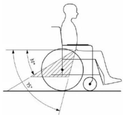
- Adjust the belt tightly according to the instructions of the strap-system manufacturer, consistent with the user's comfort.
- Ensure that the restraint belt connects in a straight line to the anchor point in the vehicle and that no bends in the belt are visible, for instance at the axle of the rear wheel.
- Install the armrests, if desired. Make sure that belts are not twisted or held away from the body by wheelchair components such as armrests or wheels.
- Position the seatbelt buckle so that the release button will not be contacted by wheelchair components during a crash.
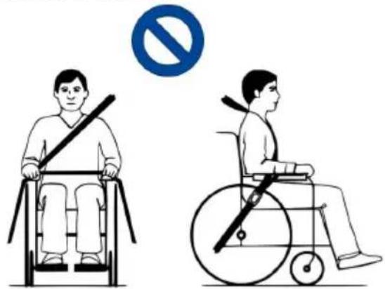
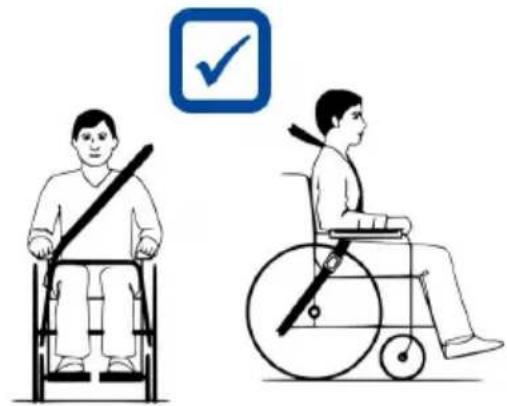
- Make sure that the shoulder-belt restraints fit over the shoulders, see figure 4.
Belt restraints must not be held away from the body by wheelchair components such as armrests or wheels.
natural_image
Illustration showing two individuals in wheelchairs, one using a horizontal barbell and the other in a wheelchair, with no visible text or symbols.Figure 3
Belt restraints make full contact with shoulder, chest and pelvis. Pelvic belt low on the pelvis near the thigh-abdominal junction
natural_image
Illustration of two individuals in wheelchairs, one using a bandage and the other seated in a wheelchair, both with a checkmark icon (no text or symbols)Figure 4
2.5. Assembly/Disassembly
EN
CAUTION
Risk of injuries
- Make sure that your fingers, clothes, buckles won't get trapped during (dis)assembly.
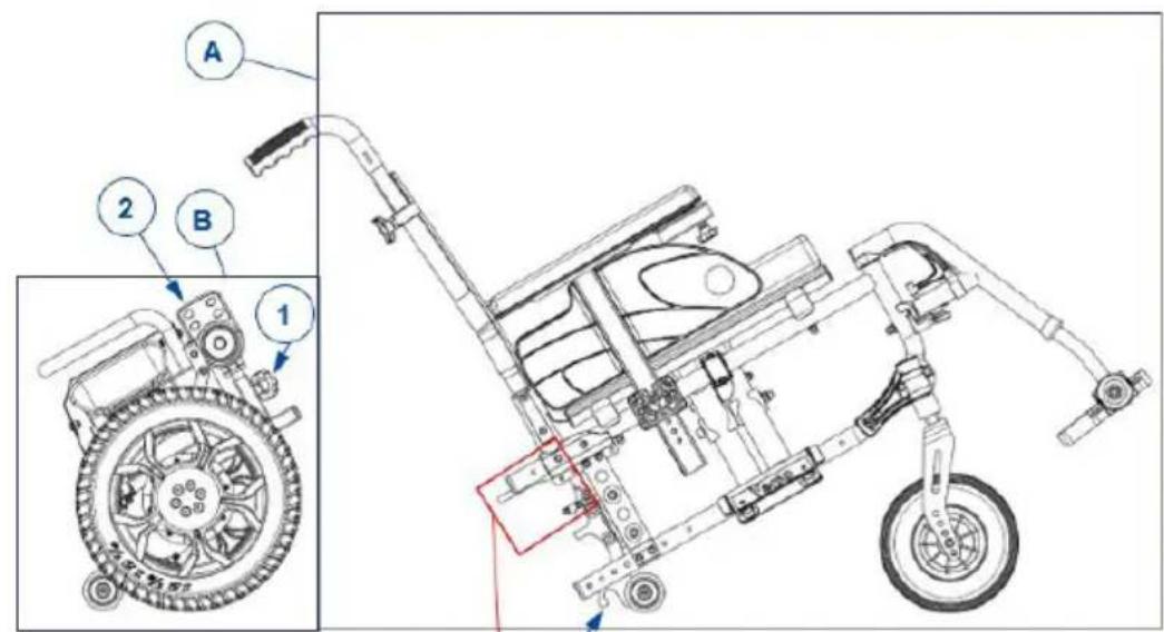
To assemble the powered wheelchair:
- Unfold the seating frame (A).
- Place the seating frame on the front wheels and the rear support wheels.
- Place the drive train (B) unit behind the seating frame.
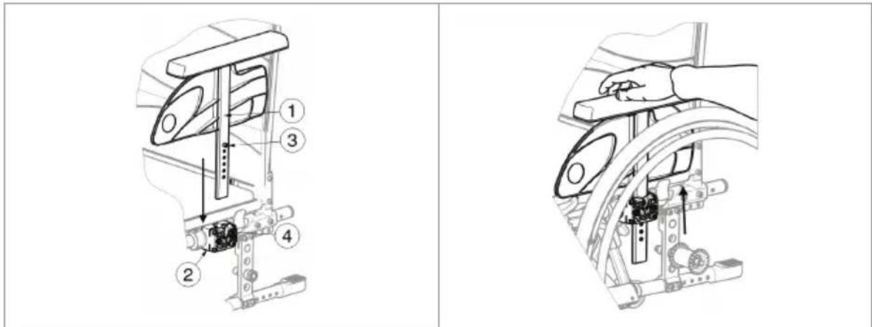
- Unscrew the star knob (1) and remove the operating console (2) from the drive train unit. Place the console in a temporary safe place, e.g. place it over the backrest.
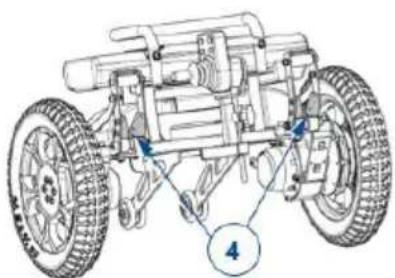
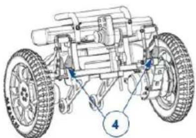
- Place the hooks of the seat frame (3) on the rods (4) of the drive train unit.
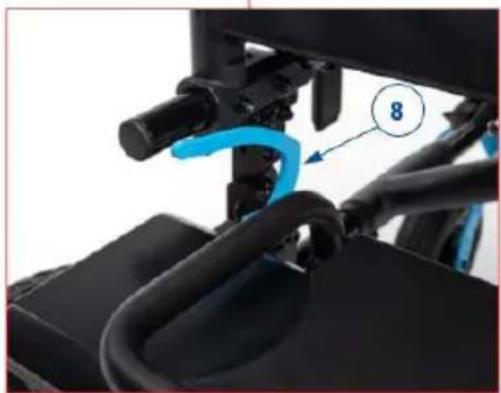
- Push the seating frame down until an audible click is heard and the frame is securely attached to the drive train unit, both left and right. Check that the hooks (8) are locked in downward position. If the seat frame does not click automatically, place the frame on the drive train unit and push the hooks (8) down manually.
- Mount the arm supports (§3.7.2.).
- Mount the footrests (§3.7.3.).
- If applicable, connect the cables of the lighting system (to be plugged together above the battery).
- Slide the operating console into the support on the armrest (5). Tighten the star knob (6) and secure the cable with the clamps (7).
To disassemble the powered wheelchair:
-
Release the cable from the clamps on the armrest. Loosen the star knob (6) on the operating console support and slide the console out. Place the console in a temporary safe place.
-
If applicable, disconnect the cables of the lighting system (to be unplugged above the battery).
-
Pull the hooks (8) on both sides of the lower frame upwards. The drive train unit is now released from the frame and will tilt backwards onto its support wheels.
- Lift the seating frame up and away from the drive train unit.
- Remove the arm supports.
- Remove the footrests.
- Fold the seating frame.
- Place the operating console (2) into the designated support on the drive train unit and tighten the star knob (1).
natural_image
Technical line drawing of a vehicle chassis with four wheels and labeled components (no text or symbols beyond labels)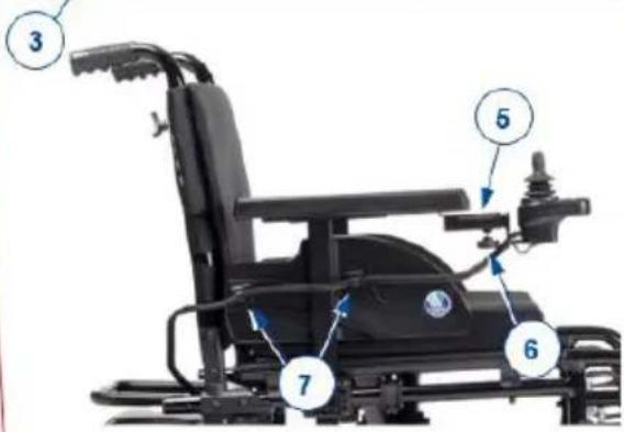

natural_image
Close-up of a mechanical device with blue tool and numbered component (no visible text or symbols)2.6. First use and storage
EN
CAUTION
Risk of battery damage
- Never completely discharge the battery.
- Do not interrupt the charging cycle; only disconnect the battery charger when the battery is fully charged.
- Make sure that your wheelchair is stored in a dry environment to prevent mould from growing and the upholstery from being damaged, see also chapter 6..
- When your product is not used on a daily basis, make sure to switch off the battery as well as the drive electronics, see §3.3. and §3.8.2..
Ensure that the battery has been fully charged before using your wheelchair, ask your dealer if this has already been done or not. To charge, follow the charging instructions in §3.8..
If the packaging of your product has been damaged, (unintentionally) opened, or affected by environmental conditions (moisture, heat,...) upon delivery, check the device integrity of your product. When in doubt, contact your specialist dealer.
3. Using your wheelchair
WARNING
Risk of injuries
- First read previous chapters and inform yourself about the intended use. Do NOT use your wheelchair unless you have read and fully understood all instructions.
- Also read the instructions in the battery charger manual!
- In case of doubts or questions, do not hesitate to contact your local specialist dealer, your care provider or technical adviser to help you with this.
3.1. First ride
CAUTION
Risk of injuries and damage
- Always keep the swing range of footrest and operating console in mind to prevent bystanders from being injured or objects from being damaged.
-
Always unplug the battery charger from the wheelchair before starting to drive.
Make sure that you are familiar with the operation of your wheelchair before using it in crowded and possibly dangerous places. First exercise at a spacious, open area with little bystanders.
i Investigate the effects of shifting the centre of gravity on the behaviour of the wheelchair, for example on up or down gradients, on laterally sloping ground, or when overcoming obstacles. Obtain support from an attendant.
The surface of the controller gets slightly warm during use.
i While driving backwards, the speed is reduced. -
Make sure that
– the wheelchair is on a flat surface;
– the battery is fully charged, see § 3.8.;
– the motor is coupled, see § 3.5.;
- the tyres have the correct tyre pressure (if applicable), see § 4.2.1.;
– the wheelchair is adapted to your needs and comfort, see §3.7.;
- you have the proper sitting position, see § 3.6.2..
- Switch on your wheelchair.
- Turn the speed control to the lowest speed setting.
- Exercise how to drive and make adjustments to the wheelchair.
- If you feel confident enough, you can try to drive at higher speed.
- Now try to turn, in forward and backward direction. Repeat this a few times.
- Make sure that your wheelchair stands stable when ending the ride.
- Switch off your wheelchair.
3.2. Driving outdoors
EN
WARNING
Risk of accident - Adjust your driving behaviour and speed.
- Take the local road traffic law into consideration; it may differ per country. This counts for driving on pavements, unpaved roads or paved roadways.
- Do not drive on roads with heavy traffic.
- Take the weather conditions into consideration. Avoid driving by moist weather, extreme heat, snow, black ice, freezing temperatures; see technical specifications in chapter 6..
- Even with your wheelchair lights on, it is not suitable to drive on public roads at poor visibility (darkness, mist, twilight). Make sure that you are well visible, also during daylight hours, by using fluorescent clothing and/or by using own lighting at the front and rear side of the wheelchair.
- Be aware of other road users to whom your wheelchair may be an obstacle. Pay special attention during turning and reversing. If you are not acquainted with how to drive backwards, first practice in an open area. Indicate the direction you are intending to go before turning.
- Try to drive straight in small passages to prevent getting trapped.
- Keep the braking distance in mind. Be aware that the braking distance depends on speed, surface, weather conditions, slope and weight of the user.
3.2.1. Cope with slopes, kerbs, obstacles or ramps
CAUTION
Risk of injuries
• Use a restraining safety belt to secure yourself sitting in the wheelchair.
- Pay attention if the road is sandy, has soft ground, holes or gaps that may cause entrapment of the wheels and/or decreasing of the traction of the driving wheels.
- Do NOT drive on slopes, obstacles, steps or kerbs larger than specified in § 6..
• Always approach a kerb from the front.
- Do not put your wheelchair in free-wheel mode on a slope. The wheelchair may start moving, causing injuries to you or bystanders.
- Do not use your wheelchair on an escalator or stairs.
- Only use ramps approved by Vermeiren and do not exceed their maximum load.
- To safely overcome obstacles or slopes, put the wheelchair in its most upright sitting position.
When you stop on a slope, the brake will work automatically to prevent the wheelchair from running forward or backward.
CAUTION
Risk of damage
- Always park your powered wheelchair on horizontal flat surfaces and on sites that are easily accessible.
- If necessary, take a short run-up to speed up the wheelchair to mount a slope, obstacle, kerb or ramp. Prevent that you or your wheelchair has to cope with a large recoil.
- Make sure that the wheelchair does not touch the ground or ramp due to the inclination of the wheelchair.
-
Be aware that the braking distance on downhill slopes can be significantly larger than on level ground.
-
Start your drive according to the instructions in § 3.1., step 1.
-
To move the wheelchair up or down stairs/steps, use lifting equipment or a ramp. If these are not available, it can be lifted manually by at least two persons, grasping the frame firmly with both hands. Do not use the backrest, footplate(s), armrests, or wheels to grasp the wheelchair.
-
To cope with obstacles or inclinations:
-
Adjust the wheelchair to its most stable position, see § 3.6.3..
- Drive as slow as possible to cope with the obstacle or inclination.
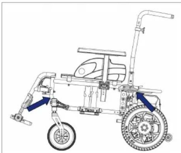
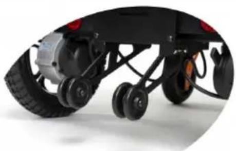
3.2.2. Anti-tipping / Tipping aid
The drive train unit is fitted with anti-tipping wheels doubling as tipping aids. They prevent the wheelchair from tipping backwards and can be used by an attendant to tip the wheelchair in case of small obstacles.
natural_image
Close-up of a black electric vehicle chassis with visible wheels and suspension components (no text or symbols)3.3. Operating console
Put the joystick in the neutral (central) position before pressing the on/off button, otherwise the electronics will be blocked. To release this block, switch the operating console off and on again.
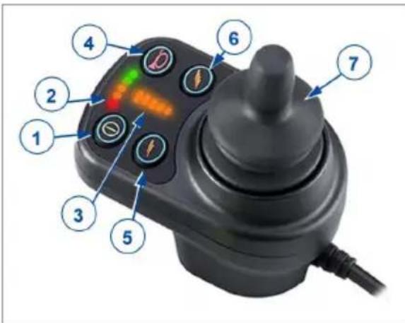
- ON/OFF button
- Battery charge indicator
- Speed indicator
- Horn button
- Speed decrease button
- Speed increase button
- Joystick
3.3.1. Technical protections
For your own safety, and to prevent that the wheelchair gets damaged, movements are monitored by the electronics. This may result in speed decrease or complete stop.
To avoid accidental battery run down, your wheelchair is equipped with an automatic power shutdown system. This system switches off the operating console automatically when it is not operated for a while. If this occurs, simply switch your console back on.
3.3.2. Driving
- Press the ON/OFF button (1) to switch on the wheelchair.
- If the lights of the battery charge indicator (2) and speed indicator (3) go on, the wheelchair is powered and ready to go.
- Check the battery status indicator. Charge the battery if necessary (see §3.8.).
- Adjust the driving speed: decrease the speed with the speed decrease button (5), or increase the speed with the speed increase button (6).
- Start moving the wheelchair by operating the joystick (7) slowly forwards/backwards.
- The speed will increase when you push the joystick further out of the centre.
- To turn left or right, push the joystick to the left or right.
- To brake, move the joystick to neutral position.
- Press the horn button (4) to alert other road users if necessary.
- After arrival, check the battery status and press the ON/OFF button to switch off the wheelchair.
- Charge the battery if necessary.
3.3.3. Operating console lock
The lock function is primarily used to prevent unauthorized use of the wheelchair, but it can also help prevent unintentional use of the controls when the system is not used for any length of time. When the system is locked, the system is powered down and the user controls are not responsive.
3.3.3.1. To lock the system
- While the system is switched on, press and hold the ON/OFF button.
- After 1 second, the system will beep. Now release the ON/OFF button.
- Push the joystick forward until the system beeps.
- Push the joystick backwards until the system beeps.
- Release the joystick. There will be a long beep.
- The system is now locked.
3.3.3.2. To unlock the system
- Use the ON/OFF button to switch the system on. The lights of the speed indicator will ripple up and down.
- Push the joystick forward until the system beeps.
- Push the joystick backwards until the system beeps.
- Release the joystick. There will be a long beep.
- The system is now unlocked.
3.4. Operating the lights (optional)
When your wheelchair is fitted with the optional lighting system, an extra console is mounted to the arm pad opposite of the operating console. Before you start your drive, make sure that the lighting system cables have been connected.

- Left indicator
- Right indicator
- Hazard lights
- Driving lights
To activate any of the lights, press the appropriate button once. To switch off the lights, press the button again.
3.5. Brake and free-wheel lever
CAUTION
Risk of injuries or damage
- Only operate the free-wheel lever when your wheelchair is turned OFF. An attendant should operate the free-wheel lever. NEVER operate it from sitting position.
- Do not use the free-wheel mode on slopes and inclinations, see symbol on motor:

Make sure that the free-wheel lever is in its braking position BEFORE switching the wheelchair ON. Electromagnetic brakes do NOT function if the wheelchair is in free-wheel mode. This is indicated on the operating console. Driving is not possible.
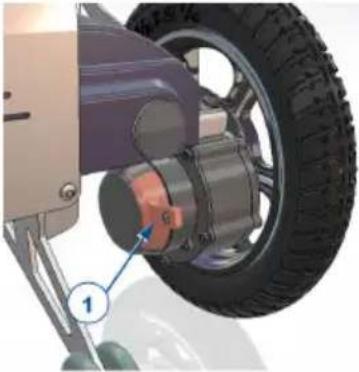
Your wheelchair is equipped with electromagnetic brakes. The working of the brakes depends on the position of the free-wheel lever (1).
The EM brakes function automatically, only if free-wheel lever (1) is in braking position. In this situation, the brakes start braking if:
- the wheelchair is OFF;
- the wheelchair is ON and the joystick is released.
Releasing the joystick makes the wheelchair stop gently and activates the brakes.
3.5.1. Operation of free-wheel lever
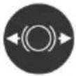 | Turn levers to the “Neutral” symbol to put the wheelchair in free-wheel mode. The motor is now disconnected. The wheelchair can be moved manually. |
 | Turn levers to the “Drive” symbol to connect the motor to the drive. This should be done before starting the wheelchair. |
 | |
3.6. Transfer to/from the wheelchair.
CAUTION
Risk of injuries or damage
- In case you cannot perform the transfer in a safe manner, ask someone to assist you.
- Do not stand on the footplates.
3.6.1. Transfer
- Position the wheelchair as close as possible to the chair, couch or bed to/from which you wish to transfer.
- Apply the brakes by turning the free-wheel lever to braking position, see § 3.5..
- Fold the footplates upwards to prevent standing on them.
- If necessary, remove one armrest to make room, see § 3.7.2..
- Transfer to/from the wheelchair using the strength of your arms or with the help of attendant(s) or lifting equipment.
3.6.2. Sitting in the wheelchair
- Sit down on the seat with your lower back against the backrest.
- Turn the footplate(s) down and put your feet on the footplates.
- Replace the armrests, if applicable.
- Make sure that your upper legs are horizontal and that your feet are in a comfortable position. Adjust if necessary.
- Make sure that your arms are bent and are resting comfortably on the arm pads. Adjust if necessary.
3.6.3. Adjusting to stable position
For transport purposes and when you need to negotiate obstacles, the wheelchair must be adjusted to maximise its stability:
- Backrest upright
- Footplate folded up or adjusted to a higher position to prevent touching the obstacle
- Operating console turned inwards
3.7. Comfort adjustments
CAUTION
Risk of injuries or damage
- The following comfort adjustments can be done by the attendant or caretaker. All other adjustments are done by your specialist dealer according to the installation instructions, see preface.
- Make sure that your fingers, clothes, buckles don't get trapped during adjustment.
3.7.1. Safety belt
Fasten the safety belt by clicking the buckle into the receiver. If necessary, adjust the length of the straps.
To open the seat belt, press the red button.
3.7.2. Mounting or removing the armrests
EN
The armrests of the wheelchair can be mounted by following instructions.
- Mount the armrest in the armrest support until the screw fits in the sleeve.
- Make sure the armrest is firmly fixated.
To remove the armrest:
- Grasp the arm pad and pull the armrest gently out of the armrest support.
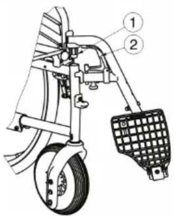
3.7.3. Mounting or removing the footrests
Mounting the footrests is done as follows:
- Hold the footrest sideways at the outside of the wheelchair's frame and mount the tube hood (1) into the frame.
- Swing the footrest inwards until it clicks in position.
- Swing the footplate downwards.
To take off the footrests:
- Pull lever.
- Swing the footrest to the outside of the wheelchair until it comes loose from the guidance.
- Pull the footrest from the tube hood (1).
3.7.4. Backrest height
The backrest height can be adjusted into 5 positions.
natural_image
Close-up of a black robotic arm with a numbered label pointing to the handle (no text or symbols on the arm itself)-
Remove the star knob (1).
-
Slide the backrest upholstery up/down to the desired height. Make sure that the hole for the star knob in the frame tube aligns with one of the holes in the upholstery.
-
Replace the star knob and retighten.
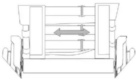
3.7.5. Backrest support
The backrest of the wheelchair has a suspension system with adjustable hook-and-loop straps, to adjust the flexibility of the backrest.
- Pull the backrest cushion from the hook-and-loop straps of the backrest.
- Loosen the hook-and-loop straps.
- Pull the respective strap to the desired position. The tension of the individual belts can be varied and the desired support of the back can be set.
-
Place the back cushion back over the backrest starting at the front and ending at the back.
-
Secure the hook-and-loop connections by pressing the cushion against the backrest with your hand.
- Make sure that all straps are secured with the hook-and-loop patches.
natural_image
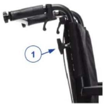
Technical line drawing of a mechanical assembly with no visible text or symbols3.7.6. Push handle height
The push handles can be adjusted over a distance of 60 mm:
| 1. Loosen the star knob (1). 2. Move the handgrip up/down to the desired height. 3. Retighten the star knob (1). 4. Repeat for the other handle. Make sure that both handles are firmly secured. |
3.7.7. Backrest inclination (Optional)
WARNING
Risk of injuries
- Be aware that the stability decreases when backrest is adjusted backwards.
- Apply the parking brakes before adjusting the backrest.
- Backrest inclination is not compatible with the optional 24" rear wheel kit.
Risk of injuries
- Do not place your fingers, clothes between the adjustment mechanism.
It is possible to set the backrest backwards with a maximum inclination of 30^ . Make sure that the patient sits in the chair when the attendant adjusts the backrest inclination and that the wheelchair does not tip over.
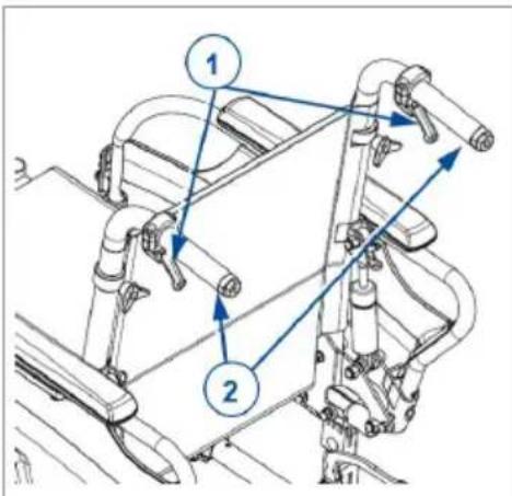
-
Pull the lever (1) on both sides towards the push handle (2) to adjust the backrest.
-
The gas spring is released.
-
Pull both back tubes backwards continuously to the desired position.
-
Release the levers.
3.8. Battery status and charging
WARNING
Risk of injuries and damage due to fire
- Only use the battery charger delivered with the wheelchair. The use of any other charger may be dangerous (fire hazard).
- The battery charger is only intended to charge the batteries delivered with the wheelchair, not to charge any other batteries.
- Do not adapt any of the delivered parts, like cables, plugs or battery charger. Never open or change the battery or the connection points.
- Protect the battery and battery charger against flames, high and low temperatures (see chapter 6.), moisture, sunshine, severe shocks (for example dropping). Do NOT use the battery if this has been the case.
• Do not charge or use a damaged battery, contact your specialist dealer. - Charge the battery with the battery charger, indoors, in a well-ventilated area, out of children's reach.
Risk of damage
- Battery self-discharge and the quiescent current of the connected users will drain the battery charge slowly. The battery may be irreversibly damaged if the battery is fully discharged. Therefore, make sure that the battery is charged on time.
- When your product is not used on a daily basis, make sure to switch off the battery as well as the drive electronics, see §3.3. and §3.8.2..
- Read the storage and maintenance instructions in §4.2. and technical details in §6..
- Do not charge batteries below 0^ C. Move the battery to a warmer place and start charging.
- Keep the connection point for the battery charger free of dust and other contamination.
- In case of any problems due to which the battery cannot be charged according to the following instructions, please contact your specialist dealer.
For all information on battery status indication, please read §3.8.1.. It is recommended to unplug the battery charger from the mains when not in use. This is to prevent unnecessary energy consumption.
Always check the battery for damage before charging. Press the charge indicator button for 2 seconds to switch on the battery. When no LED of the charge indicator lights up, the battery may be damaged. When at least one, but not all LEDs of the charge indicator, is lit, then fully charge the battery pack before using for the first time.
Instructions to charge the battery:
- Switch the battery off.
- If desired, remove the battery from the battery housing and prevent dirt or fluids from entering the charging socket.
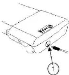
- Connect the charger plug to the battery pack (1) or the socket on the operating console.
-
Connect the charger mains plug into the wall socket.
-
The LED indicator on the battery charger will show the status of the charging process:
-
Red - Charging
-
Green - Standby / Fully Charged
-
Once the battery is fully charged, remove the battery charger from the wall socket and the battery.
3.8.1. Battery charge indicator
There are two battery charge indicators:
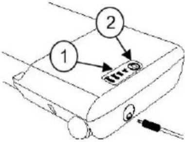 | 3.8.1.1. On the battery pack:1. Press button (2) on the battery pack.2. The LED's of the battery charge indicator (1) will indicate the battery charge level. |
 | 3.8.1.2. On the operator console:When the electric system is switched on, the battery indicator (2, §3.3.) will indicate the battery charge level.All LEDs on: battery fully charged.Only red LED on or blinking: immediately recharge battery. |
Because of the wiring, both indications can deviate a little bit. In that case, take the worst charge level indication.
EN
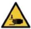
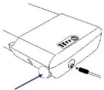
3.8.2. Switching the electric device On/Off
Press the on/off switch on the side of the battery.
natural_image
Line drawing of a device with a label 'HTR' and two cables attached (no text or symbols on the device itself)3.8.3. Mounting / removing the battery
 |  | Unlock |
 | Lock |
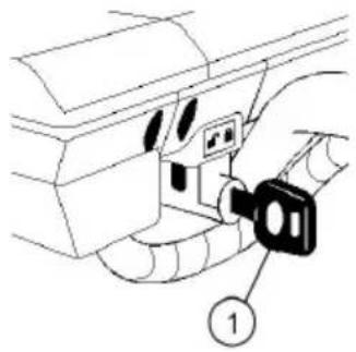
The battery can be removed for easy charging away from the wheelchair.
To mount the battery:
- Place the key (1) and turn the key towards the unlock symbol.
- Place the battery in the battery housing as far as possible. There is only 1 possible way to insert the battery.
- Turn the key (1) to the lock symbol.
- Make sure that the battery is fixed well.
- Remove the key (1). (Never remove the key while riding).
To remove the battery:
- Place the key (1).
- Turn the key (1) to the unlock symbol.
- Pull the battery gently out of the battery housing.
4. Maintenance
i Regular care ensures that your wheelchair is preserved in a perfectly functional condition. For the maintenance manual, refer to the Vermeiren website: www.vermeiren.com.
4.1. Points of maintenance
CAUTION
Risk of injuries and damage
- Repairs and replacements may only be undertaken by trained persons and only genuine replacement parts of Vermeiren should be used.
The last page of this manual contains a registration form for the specialist dealer to record each service.
The service frequency depends on the frequency and intensity of use. Contact your dealer to agree to a common timetable for inspection/maintenance/repair.
i Read the user instructions of the applied battery charger regarding maintenance.
4.1.1. Before each use
Inspect the following points:
-
All parts: Present and undamaged or unworn.
• All parts: Clean, see § 4.2.2.. -
Wheels, seat, arm rests, footrests and headrest (if applied): well secured.
- Battery status: charge the battery when necessary, see §3.8..
- Operating console, battery, power module, motors, battery charger, lights and relevant cables: no damage such as wires that have become frayed, broken or exposed.
• Condition of wheels/tyres, see § 4.2.1.. - Condition of frame parts: No deformation, instability, weakness or loose connections.
- Seat, backrest, arm pads, calf pads and head rest (if applied): No excessive wear (like dented spots, damage or tears).
Contact your specialist dealer for possible repairs or part replacements.
4.1.2. Yearly or more often
Have your wheelchair inspected and serviced by your specialist dealer, at least once a year, or more often. The minimum maintenance frequency depends on use and should therefore be commonly agreed upon with your specialist dealer.
4.1.3. If stored
Make sure that your wheelchair is stored in a dry environment to prevent mould from growing and the upholstery from being damaged, see also chapter 6..
If your wheelchair is stored for a longer period, you still need to charge the batteries every month.
When your product is not used on a daily basis, make sure to switch off the battery as well as the drive electronics, see §3.3. and §3.8.2..
4.2. Maintenance instructions
4.2.1. Wheels and tyres
Proper working of the brakes depends on the state of the tyres, and can change due to wear and contamination (water, oil, mud, ...).
Keep your wheels free of wires, hair, sand and fibres.
Check the profile of the tyres. If the tread depth is less than 1 mm, the tyres need to be replaced. Contact your specialist dealer for this matter.
Inflate each pneumatic tyre to the correct pressure (see pressure indication on the tyres).
4.2.2. Cleaning
CAUTION
Risk of damage by moisture
- Never use a hose or high-pressure cleaner to clean the wheelchair.
- Keep the operating console clean and protect it from water and rain.
Wipe all rigid parts with a damp cloth (not drenched). If necessary, use a mild soap, suitable for varnishes and synthetics.
The upholstery can be cleaned with lukewarm water and a mild soap. Do not use abrasive cleaning agents to clean.
Keep the ventilation openings of the battery charger clean and free of accumulated dust. Blow away the dust and clean the battery charger enclosure with a slightly moistened cloth, if required.
4.2.3. Disinfection
EN
CAUTION
Risk of damage
- Disinfections may only be undertaken by trained persons. Consult your specialist dealer.
4.3. Expected lifespan
The wheelchair is designed to have an average lifespan of 5 years. Depending on the frequency of use, driving circumstances and maintenance, the lifespan of your wheelchair will increase or decrease.
4.4. Reuse
Before each reuse, have the wheelchair disinfected, inspected and serviced according to the instructions in § 4.1. and § 4.2..
4.5. End of use
At end of life, you need to dispose your wheelchair according to the local environmental legislation. The best way to do so, is to disassemble the wheelchair to facilitate the transport of recyclable parts.
4.6. Warranty
The warranty on this product is subject to the general terms and conditions of each country.
5. Troubleshooting
Even if you use your wheelchair properly, a technical problem may occur. In this case, contact your local specialist dealer.
WARNING
Risk of injuries and damage
- NEVER attempt to repair your wheelchair yourself.
- For problems in the operating console you need to contact your specialist dealer. He/She will decide if the console needs to be reprogrammed.
The following symptoms may indicate a serious problem. Therefore always contact your specialist dealer if you spot any of the following deviations:
- Strange sound;
- Frayed/damaged wiring harnesses;
- Cracked or broken connectors;
- Uneven tread wear on one of the tyres;
- Jerky movements;
- Wheelchair deflects to one side;
- Damaged or broken wheel assemblies.
- Wheelchair does not switch on (blown fuse);
• Wheelchair is powered but does not move, see 3.5..
In case of a possible problem, a system code is displayed by the blinking LEDs of the battery status indicator, see §3.3. (2). The following table summarises the possible system codes (number of blinks). Some problems can be solved by yourself. For all problems marked with a star (*), consult your specialist dealer.
| Code Problem Meaning | ||
| 1 Empty battery / bad connection to battery | Check the connections to the batteries. If the connections are good, try charging the batteries. | |
| 2 * Bad connection of left motor or encoder | Check the connections to the left hand motor and encoder. | |
| 3 * Faulty wiring on left hand motor / stall condition | ||
| 4 * Bad connection of right motor or encoder | Check the connections to the right hand motor and encoder. | |
| 5 * Faulty wiring on right hand motor / stall condition | ||
| 7 Joystick fault Make sure that the joystick is in the centre position before switching on the controller. | ||
| 7 + S1 | * Communication fault Make sure that the joystick module cable is securely connected and not damaged. | |
| 8 * Possible controller fault Make sure that all connections are secure. | ||
| 9 Parking brake bad connection | Check the parking brake and motor connections. Make sure the controller connections are secure. | |
| 10 * Excessive voltage Excessive voltage is usually caused by a poor battery connection. Check the battery connections. | ||
| 1S = Flashing speed indicator LEDs | ||
EN
6. Technical specifications
The technical details below are only valid for this wheelchair, at standard settings and optimal ambient conditions. Take these details into account during use. The values are no longer applicable if your wheelchair has been modified, damaged, or is severely worn. Be aware that the driving performance is influenced by ambient temperature, humidity, slopes (driving up/down), type of surface and battery status.
| Brand Vermeiren | |
| Product group Powered wheelchair, Class A | |
| Type Verso | |
| Description Dimensions | |
| Maximum user weight 130 kg | |
| Overall length with footrest 1078 mm (in shortest seat depth)Backrest 30°: 1137 mm (in shortest seat depth) | |
| Overall width (depends on the seat width) 560 mm590 mm610 mm630 mm650 mm670 mm | |
| Overall height 937 mm - 1002 mm | |
| Total mass 31,3 kg | Backrest 30°: 35 kg |
| Mass of heaviest part Rear frame: 16,2 kg | |
| Energy consumption * | 12,8 Ah: 15 km17,5 Ah: 21 km |
| Rated slope | 10° |
| Obstacle climbing | 15 mm |
| Maximum speed forward | 6 km/h |
| Max. braking distance from max. speed | 1 m |
| Seat plane angle | 5° |
| Effective seat depth | 420 - 480 mm |
| Effective seat width | 390 mm420 mm440 mm460 mm480 mm500 mm |
| Seat surface height at front edge 521 mm | |
| Backrest angle 5° | Backrest 30°: 5° - 35° |
| Backrest height 400 - 420 - 440 - 460 - 480 mm | |
| Footplate to seat distance 370 - 500 mm | |
| Leg to seat surface angle 105° | |
| Armrest to seat distance 150 – 210 mm | |
| Front location of arm pad structure 322,5 mm – 370 mm | |
| Minimum turning diameter 1145 mm | |
| Ground clearance 61 mm | |
| Diameter of rear wheels 12" | |
| Diameter of front wheels | 200 x 50 mm |
| Tyre pressure (air tyres only) | Max. 2,5 bar |
| Battery | 12,8 Ah17,5 Ah |
| Driving motors | 250W |
| Blow fuse (only with lights) | 20 A |
| Noise level | < 65 dB(A) |
| Degree of protection | IPX4 |
| Strength tests according to | ISO 7176-8 |
| Tests of power and control system according to | ISO 7176-14 |
| Ignitability of upholstery according to | EN 1021-2:2006 |
| EMC compliance | ISO 7176-21 |
| Storage and use temperature | +5°C - +41°C |
| Operating temperature for electronics | -10°C - +40°C |
| Storage and use humidity | 30% - 70% |
| We reserve the right to introduce technical changes. Measurement tolerance +- 15 mm / 1,5 kg / 1,5°* The theoretical driving distance will be reduced if the wheelchair is used frequently on slopes, rough ground or to climb curbs. | |
EN
Table des matières
Préface
43
1. Votre produit 45
1.1. Options 46
natural_image
Close-up of a black motorcycle rear bumper with red circles highlighting the front wheel and side-mounted sensors (no visible text or symbols)natural_image
Technical line drawing of a wheeled robotic vehicle with visible wheels, suspension components, and no text or symbolsFigure 1
Figure 2
natural_image
Illustration showing two individuals: one in a wheelchair and another in a wheelchair, both without any text or symbols.Figure 3
natural_image
Illustration of two individuals in wheelchairs, one using a diagonal brace and the other seated in a wheelchair, both with a checkmark icon above (no text or symbols on figures)Figure 4
ATTENTION
natural_image
Close-up of a black electric vehicle chassis with visible wheels and suspension components (no text or symbols)natural_image
Close-up of a black mechanical device with a numbered label pointing to a component (no text or symbols on the device itself)natural_image
Technical line drawing of a mechanical assembly with two vertical supports and a central horizontal double-headed arrow (no text or symbols)natural_image
Close-up of a black robotic arm with a blue circular annotation pointing to a numbered component (no text or symbols on the arm itself)natural_image
Black handheld joystick controller with control buttons and a green indicator light (no text or symbols visible)natural_image
Line drawing of a device with a labeled component and two cables (no text or symbols)natural_image
Diagram of a car's internal component with a numbered label (1) pointing to a key inserted into the main body area.
Déverrouillage

Verrouillage
natural_image
Close-up of a black motorcycle rear bumper with red circles highlighting mechanical components (no readable text or symbols)natural_image
Technical line drawing of a wheeled wheelchair with articulated limbs and wheel (no text or symbols)Figuur 1
Figuur 2
natural_image
Illustration showing a person in a wheelchair and another in a wheelchair, both without any text or symbols.Figuur 3
natural_image
Illustration of two individuals in wheelchairs, one using a diagonal brace and the other seated in a wheelchair, both with a checkmark icon above (no text or symbols on figures)Figuur 4
2.5. Montage/Demontage
VOORZICHTIG
Gevaar voor letsel
natural_image
Technical line drawing of a vehicle chassis with four wheels and labeled components (no text or symbols present)
natural_image
Close-up of a mechanical device with blue tool and numbered component (8), no visible text or symbols3.2.2. Anti-tipping / Tiphulp
natural_image
Close-up of a black electric vehicle chassis with visible wheels and suspension components (no text or symbols)3.3. Besturing
NL
3.7.4. Rughoogte
natural_image
Close-up of a black mechanical device with a labeled component (1) pointing to a curved arm and handle (no text or symbols beyond label)natural_image
Technical line drawing of a mechanical assembly with two vertical supports and a central horizontal double-headed arrow (no text or symbols)3.7.6. Handvathoogte
NL
natural_image
Close-up of a black robotic arm with a blue circular annotation pointing to a numbered component (no text or symbols on the arm itself)natural_image
Line drawing of a device with a label and two cables (no readable text or symbols)natural_image
Close-up of a black Verso motorcycle rear bumper with red circular annotations highlighting mechanical components (no readable text beyond branding)natural_image
Illustration showing two individuals in wheelchairs, one using a horizontal barbell and the other seated in a wheelchair, with no visible text or symbols.Abb. 3
natural_image
Illustration showing a person in a wheelchair and another in a wheelchair, both with a checkmark icon (no text or symbols)Abb. 4
2.5. Montage/Demontage
⚠VORSICHT
Verletzungsgefahr
DE
natural_image
Close-up of a black electric vehicle chassis with visible wheels and suspension components (no text or symbols)3.3. Bedienkonsole
DE
natural_image
Mechanical assembly diagram showing a car wheel and suspension components (no text or symbols)DE
natural_image
Close-up of a black robotic arm with a numbered label pointing to the arm (no text or symbols on the device itself)natural_image
Technical line drawing of a mechanical assembly with two vertical supports and a central double-headed arrow indicating rotation (no text or symbols)natural_image
Close-up of a black mechanical device with a numbered label pointing to a component (no text or symbols on the device itself)natural_image
Diagram of a device with labeled ports and connectors (no readable text or symbols)natural_image
Close-up of a black motorcycle rear bumper with red circles highlighting specific parts (no readable text or symbols)natural_image
Illustration showing two individuals in wheelchairs, one using a diagonal brace and the other in a wheelchair, with no visible text or symbols.Figura 3
natural_image
Illustration of two individuals in wheelchairs, one using a diagonal brace and the other seated in a wheelchair, both with a checkmark icon above (no text or symbols on figures)Figura 4
IT
natural_image
Close-up of a black electric vehicle chassis with visible wheels and suspension components (no text or symbols)natural_image
Close-up of a black robotic arm with a labeled component (1) and handle, no visible text or symbols beyond the label.natural_image
Technical line drawing of a mechanical assembly with two vertical supports and a central horizontal arrow (no text or symbols)natural_image
Black industrial joystick controller with control buttons and a cable (no visible text or symbols)natural_image
Line drawing of a device with a label 'Irris' and connected cables (no text or symbols beyond the label)natural_image
Diagram of a car interior showing a key inserted into the seat, with no visible text or symbols
Apertura

Chiusura
natural_image
Close-up of a black motorcycle front bumper with red circular annotations highlighting mechanical components (no readable text or symbols)natural_image
Illustration showing two individuals: one in a wheelchair and another in a wheelchair, both without any text or symbols.Figura 3
natural_image
Illustration of two individuals in wheelchairs, one using a diagonal brace and the other seated in a wheelchair, both with a checkmark icon above (no text or symbols on figures)Figura 4
ES
natural_image
Close-up of a black electric vehicle chassis with visible wheels and suspension components (no text or symbols)3.3. Panel de control
ES
natural_image
Technical line drawing of a mechanical assembly with no visible text or symbolsnatural_image
Close-up of a black robotic arm with a labeled component (1) and handle, no visible text or symbols beyond the label.natural_image
Black industrial joystick controller with control buttons and a cable (no visible text or symbols)3.8.1.2. En el panel de control:
natural_image
Line drawing of a device with a label 'Irris' and connected cables (no text or symbols beyond the label)natural_image
Diagram of a car interior showing a key inserted into the seat, with no visible text or symbols

Desbloquear
Bloquear
natural_image
Close-up of a black motorcycle's rear wheel and side-mounted sensor, showing red circular annotations highlighting mechanical components (no readable text or symbols)natural_image
Illustration showing two individuals in wheelchairs, one using a horizontal barbell and the other in a wheelchair, with no visible text or symbols.Rysunek 3
natural_image
Illustration of two individuals in wheelchairs, one using a diagonal brace and the other seated in a wheelchair, with a checkmark icon above (no text or symbols on figures)Rysunek 4

natural_image
Close-up of a black electric vehicle chassis with visible wheels and suspension components (no text or symbols)PL
natural_image
Technical line drawing of a mechanical assembly with two vertical supports and a central double-headed arrow indicating direction (no text or symbols)natural_image
Close-up of a black robotic arm with a labeled component (1) pointing to the handle, no text or symbols present.natural_image
Line drawing of a device with a label and two cables (no readable text or symbols)natural_image
Close-up of a black motorcycle rear bumper with red circles highlighting mechanical components (no visible text or symbols)natural_image
Line drawing of a wheeled robotic vehicle with articulated limbs and wheels, labeled 'Obrázek 1' (no technical text or symbols on the diagram itself)Obrázek 2
natural_image
Illustration showing a person in a wheelchair and another in a wheelchair, both without any text or symbols.Obrázek 3
natural_image
Illustration of two individuals in wheelchairs, one using a diagonal brace and the other seated in a wheelchair, with a checkmark icon above (no text or symbols on figures)Obrázek 4
POZOR
Riziko zranění
natural_image
Close-up of a black vehicle chassis with visible wheels and suspension components (no text or symbols)natural_image
Mechanical assembly diagram showing a car wheel and suspension components (no text or symbols)CS
natural_image
Close-up of a black robotic arm with a numbered label pointing to the handle (no text or symbols on the arm itself)natural_image
Technical line drawing of a mechanical assembly with no visible text or symbolsnatural_image
Close-up of a black robotic arm with a labeled component (1) and no visible text or symbolsnatural_image
Line drawing of a device with a labeled component and two cables (no text or symbols)Service registration form
This product (name): ....
was inspected (I), serviced (S), repaired (R) or disinfected (D):
| By (stamp):Kind of work: I / S / R / DDate: | By (stamp):Kind of work: I / S / R / DDate: | By (stamp):Kind of work: I / S / R / DDate: |
| By (stamp):Kind of work: I / S / R / DDate: | By (stamp):Kind of work: I / S / R / DDate: | By (stamp):Kind of work: I / S / R / DDate: |
| By (stamp):Kind of work: I / S / R / DDate: | By (stamp):Kind of work: I / S / R / DDate: | By (stamp):Kind of world: I / S / R / DDate: |
| By (stamp):Kind of work: I / S / R / DDate: | By (stamp):Kind of work: I / S / R / DDate: | By (stamp):Kind of work: I / S / R / DDate: |
| By (stamp):Kind of work: I / S / R / DDate: | By (stamp):Kind of work: I / S /R / DDate: | By (stamp):Kind of work: I / S / R / DDate: |
| By (stamp):Kind of work: I / S / R / DDate: | By (stamp):Kind of work: I / S / R / DDate: | By (stamp):Kind of work: I / S / R / DDate: |
VERMEIREN GROUP
Vermeirenplein 1/15
2920 Kalmthout
Belgium
www.vermeiren.com
Version: H, 2026-02
Basic UDI-DI: 5415174VersoG7
All rights reserved, including translation.

- Contents
- Preface
- Your product 6
- Before use 7
- Using your wheelchair 17
- Maintenance 34
- Troubleshooting 38
- Technical specifications 40
- Important note
- Information available
- Your product
- Options
- Before use
- Intended use
- General safety instructions
- CAUTION
- Risk of injuries and/or damage
- Symbols on the wheelchair
- Transport
- Risk of damage
- Moving out of the way
- Transport by aircraft
- Transport by vehicle, as luggage
- WARNING
- Risk of injuries and damage
- Transport by vehicle, as seat for the user
- Risk of injuries
- Steps to secure the wheelchair in a motor vehicle:
- Steps to secure the wheelchair user:
- Assembly/Disassembly
- First use and storage
- Risk of battery damage
- Using your wheelchair
- First ride
- Driving outdoors
- Risk of accident - Adjust your driving behaviour and speed.
- Cope with slopes, kerbs, obstacles or ramps
- Anti-tipping / Tipping aid
- Operating console
- Technical protections
- Driving
- Operating console lock
- To lock the system
- To unlock the system
- Operating the lights (optional)
- Brake and free-wheel lever
- Risk of injuries or damage
- Operation of free-wheel lever
- Transfer to/from the wheelchair.
- Transfer
- Sitting in the wheelchair
- Adjusting to stable position
- Comfort adjustments
- Safety belt
- Mounting or removing the armrests
- Mounting or removing the footrests
- Backrest height
- Backrest support
- Push handle height
- Backrest inclination (Optional)
- Battery status and charging
- Risk of injuries and damage due to fire
- Battery charge indicator
- Switching the electric device On/Off
- Mounting / removing the battery
- Maintenance
- Points of maintenance
- Before each use
- Yearly or more often
- If stored
- Maintenance instructions
- Wheels and tyres
- Cleaning
- Risk of damage by moisture
- Disinfection
- Expected lifespan
- Reuse
- End of use
- Warranty
- Troubleshooting
- Technical specifications
- Table des matières
- Préface
- Votre produit 45
- ATTENTION
- Montage/Demontage
- VOORZICHTIG
- Gevaar voor letsel
- Anti-tipping / Tiphulp
- Besturing
- Rughoogte
- Handvathoogte
- ⚠VORSICHT
- Verletzungsgefahr
- Bedienkonsole
- Panel de control
- En el panel de control:
- POZOR
- Riziko zranění
- Service registration form
Brand : Vermeiren
Model : Verso
Category : Wheelchair