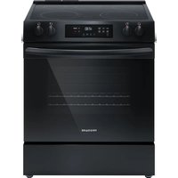
FCFE3062BK - Cooker FRIGIDAIRE - Free user manual and instructions
Find the device manual for free FCFE3062BK FRIGIDAIRE in PDF.


| Product type | Electric range |
| Brand | Frigidaire |
| Model | FCFE3062BK |
| Width | 76.2 cm (30") |
| Height | 91.4 cm (36") adjustable |
| Depth | 66 cm (26") |
| Weight | Approximately 68 kg (150 lb) |
| Power supply | 240 V, 40/50 A, single phase |
| Connection type | 3-wire or 4-wire (depending on installation) |
| Number of burners | 4 |
| Burner type | Electric radiant |
| Oven | Standard capacity, convection cooking function (not specified) |
| Safety | Anti-tip device included |
| Cleaning | Manual cleaning (no self-cleaning) |
| Surface material | Stainless steel or enamel (depending on version) |
| Color | Black (BK) |
| Spare parts | Available from manufacturer |
| Warranty | 1 year parts and labor |
| Repairability | Repairability index not provided |
Frequently Asked Questions - FCFE3062BK FRIGIDAIRE
User questions about FCFE3062BK FRIGIDAIRE
0 question about this device. Answer the ones you know or ask your own.
Ask a new question about this device
Download the instructions for your Cooker in PDF format for free! Find your manual FCFE3062BK - FRIGIDAIRE and take your electronic device back in hand. On this page are published all the documents necessary for the use of your device. FCFE3062BK by FRIGIDAIRE.
USER MANUAL FCFE3062BK FRIGIDAIRE
INSTALLATION INSTRUCTIONS
FRONT CONTROL FREESTANDING ELECTRIC RANGE
INSTALLATION AND SERVICE MUST BE PERFORMED BY A QUALIFIED INSTALLER.
IMPORTANT: SAVE FOR LOCAL ELECTRICAL INSPECTOR'S USE. READ AND SAVE THESE INSTRUCTIONS FOR FUTURE REFERENCE.
United States

WARNING FOR YOUR SAFETY: Do not store or use gasoline or other flammable vapors and liquids in the vicinity of this or any other appliance.
Canada

IMPORTANT SAFETY INSTRUCTIONS
⚠ WARNING If the information in this manual is not followed exactly, a fire or electrical shock may result causing property damage, personal injury or death.
Important Notes to the Installer:
- Read all instructions contained in these installation instructions before installing range.
- Remove all packing material from the oven compartments before connecting the gas & electrical supply to the range.
- Observe all governing codes and ordinances.
- Be sure to leave these instructions with the consumer.
Important Notes to the Consumer:
Keep these instructions with your owner's guide for future reference.
- As when using any appliance generating heat, there are certain safety precautions you should follow. These are listed in the Use & Care Guide, read it carefully.
- Be sure your range is installed and grounded properly by a qualified installer or service technician.
- Make sure the wall coverings around the range can withstand the heat generated by the range.
- To eliminate the need to reach over the surface elements, cabinet storage space above the elements should be avoided.
WARNING
Tip Over Hazard
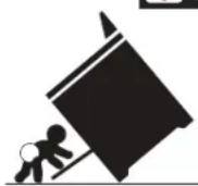
- A child or adult can tip the range and be killed.
- Verify the anti-tip device has been installed to floor or wall.
- Ensure the anti-tip device is re-engaged to floor or wall when the range is moved.
- Do not operate the range without the anti-tip device in place and engaged.
- Failure to follow these instructions can result in death or serious burns to children and adults.

Range
leveling leg
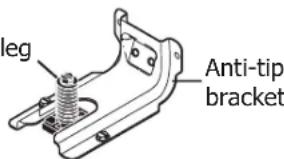
text_image
leg Anti-tip bracketTo check if the anti-tip bracket is installed properly, use both arms to grasp the rear edge of the range back. Carefully attempt to tilt range forward. When properly installed, the range should not tilt forward.
Refer to the anti-tip bracket installation instructions supplied with your range for proper installation.
30" ELECTRIC FRONT CONTROL FREESTANDING INSTALLATION INSTRUCTIONS
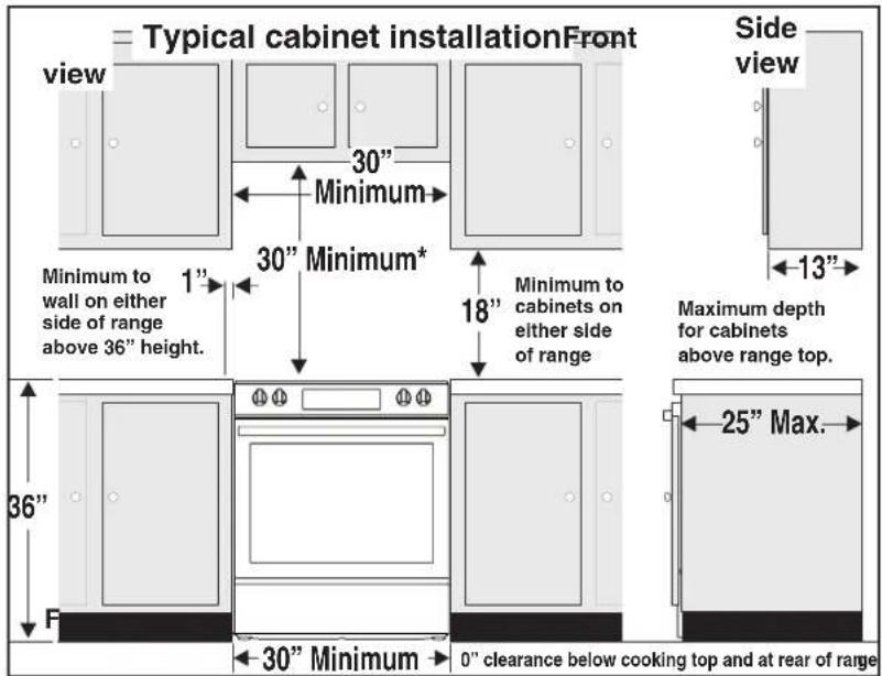
1. Clearances and Dimensions
a. Provide adequate clearances between the range and adjacent combustible surfaces.
b. Location—Check location where the range will be installed. Check for proper electrical supply and the stability of floor.
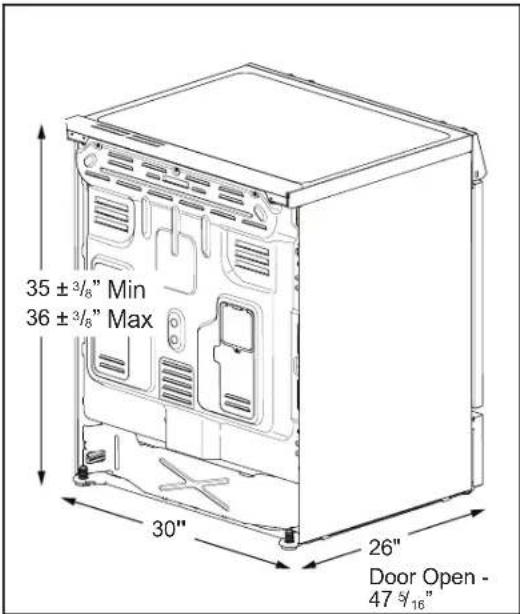
c. Dimensions that are shown must be used. Given dimensions provide minimum clearance. Contact surface must be solid and level.
text_image
Typical cabinet installationFront view 30" Minimum 30" Minimum* 1" Minimum to wall on either side of range above 36" height. 36" F 30" Minimum 0" clearance below cooking top and at rear of range Side view 18" Minimum to cabinets on either side of range 13" Maximum depth for cabinets above range top. 25" Max.Fig. 1
text_image
35 ± 3/8" Min 36 ± 3/8" Max 30" 26" Door Open - 47 3/16"Fig. 2
*30" (762 mm) MINIMUM CLEARANCE BETWEEN THE TOP OF THE COOKING SURFACE AND THE BOTTOM OF AN UNPROTECTED WOOD OR METAL CABINET; OR 24" (610 mm) MINIMUM WHEN BOTTOM OF WOOD OR METAL CABINET IS PROTECTED BY NOT LESS THAN 1/4" (6 mm) FLAME RETARDANT MILLBOARD COVERED WITH NOT LESS THAN NO. 28 MSG SHEET STEEL, 0.015" (0.4 mm) STAINLESS STEEL, 0.024" (0.6 mm) ALUMINUM OR 0.020" (0.5 mm) COPPER. 0" (0 mm) CLEARANCE IS THE MINIMUM FOR THE REAR OF THE RANGE. FOLLOW ALL DIMENSION REQUIREMENTS PROVIDED ABOVE TO PREVENT PROPERTY DAMAGE, POTENTIAL FIRE HAZARD, AND INCORRECT COUNTERTOP AND CABINET CUTS.
TO ELIMINATE THE RISK OF BURNS OR FIRE BY REACHING OVER HEATED SURFACE UNITS, CABINET STORAGE SPACE LOCATED ABOVE THE SURFACE UNITS SHOULD BE AVOIDED. IF CABINET STORAGE IS TO BE PROVIDED, THE RISK CAN BE REDUCED BY INSTALLING A RANGE HOOD THAT PROJECTS HORIZONTALLY A MINIMUM OF 5" (127 mm) BEYOND THE BOTTOM OF THE CABINETS.

text_image
Dashed cubed area shows where the electrical outlet should be installed for flush to the wall installation. Wall EdgeFig. 3
30" ELECTRIC FRONT CONTROL FREESTANDING INSTALLATION INSTRUCTIONS
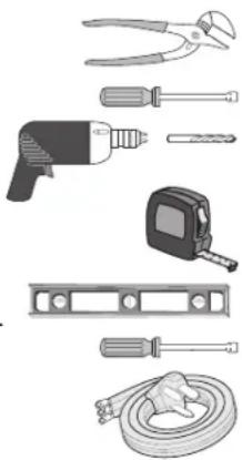
2. Tools You Will Need
For leveling legs and Anti-Tip Bracket:
- Adjustable wrench or channel lock pliers
- 5/16" Nutdriver or Flat Head Screwdriver
- Electric Drill & 1/8" Diameter Drill Bit (Masonry Drill Bit if installing in concrete)
• Level & Measuring Tape For electrical supply connection:
• 1/4" & 3/8" Socket driver or Nutdriver Additional Materials You Will Need:
• Power Supply Cord or
• Copper Electrical Wiring & Metal Conduit (for hard wiring)
natural_image
Collection of various hand tools including pliers, drill bit, tape measure, and hose (no text or symbols visible)3. Anti-Tip Bracket Installation Instructions
A WARNING To reduce the risk of tipping of the range, the range should be secured to the floor by properly installed anti-tip bracket and screws packed with the range. Failure to install the anti-tip bracket will allow the range to tip over if excessive weight is placed on an open door or if a child climbs upon it. Serious injury might result from spilled hot liquids or from the range itself.
If range is ever moved to a different location, the anti-tip brackets must also be moved and installed with the range.
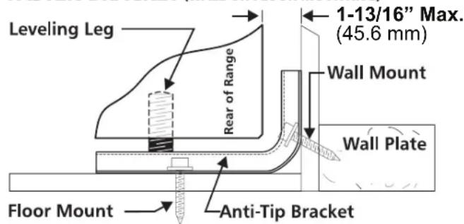
Instructions are provided for installation in wood or cement fastened to either the floor or wall. When installed to the wall, make sure that screws completely penetrate dry wall and are secured in wood or metal. When fastening to the floor or wall, be sure that screws do not penetrate electrical wiring or plumbing.
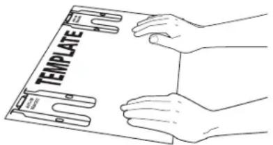
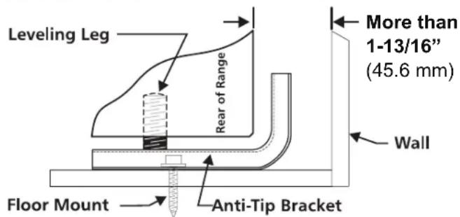
A. Locate the Bracket Using the Template - (Bracket may be located on either the left or right side of the range. Use the information below to locate the bracket if template is not available). Mark the floor or wall where left or right side of the range will be located. If rear of range is against the wall or no further than 1-13/16" (46 mm) from wall when installed, you may use the wall or floor mount method. If molding is installed and does not allow the bracket to fit flush against the wall, remove molding or mount bracket to the floor. For wall mount, locate the bracket by placing the back edge of the template against the rear wall and the side edge of template on the mark made referencing the side of the range. Place bracket on top of template and mark location of the screw holes in wall.
If rear of range is further than 1-13/16" (46 mm) from the wall when installed, attach bracket to the floor. For floor mount, locate the bracket by placing back edge of the template where the rear of the range will be located. Mark the location of the screw holes, shown in template.
text_image
TEMPLATEFig. 4
B. Drill Pilot Holes and Fasten Bracket - Drill a 1/8" (3 mm) pilot hole where screws are to be located. If bracket is to be mounted to the wall, drill pilot hole at an approximate 20° downward angle. If bracket is to be mounted to masonry or ceramic floors, drill a 5/32" (4 mm) pilot hole 1-3/4" (44 mm) deep. The screws provided may be used in wood or concrete material. Use a 5/16" (8 mm) nut-driver or flat head screwdriver to secure the bracket in place.
FASTEN BRACKET (FLOOR MOUNTING ONLY)
text_image
Leveling Leg Rear of Range More than 1-13/16" (45.6 mm) Wall Floor Mount Anti-Tip BracketFig. 5
FASTEN BRACKET (WALL OR FLOOR MOUNTING)
text_image
Leveling Leg Rear of Range 1-13/16" Max. (45.6 mm) Wall Mount Wall Plate Floor Mount Anti-Tip BracketFig. 6
30" ELECTRIC FRONT CONTROL FREESTANDING INSTALLATION INSTRUCTIONS
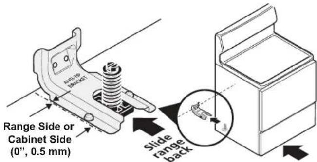
C. Level and Position Range - Level range by adjusting the (4) leveling legs with a wrench. Note: A minimum clearance of 1/8" (3 mm) is required between the bottom of the range and the leveling leg to allow room for the bracket. Use a spirit level to check your adjustments. Slide range back into position. Visually check that rear leveling leg is inserted into and fully secured by the Anti-Tip Bracket by removing lower panel or storage drawer.
text_image
SMITH 300X3T Range Side or Cabinet Side (0", 0.5 mm) Slide range backFig. 7
4. Electrical Connection Requirements
A WARNING Avoid fire hazard or electrical shock. Failure to follow this warning may casue serious injury, fire, or death.
This appliance must be properly installed and grounded by a qualified technician in accordance with the National Electrical Code ANSI/NFPA No. 70 or Canadian Electrical Code (CSA Standard (C22.1 Part 1) latest editions, and Local Electrical Code requirements.
For personal safety, this appliance must be properly grounded. For maximum safety, the power cord must be plugged into an electrical outlet that is correct voltage, is correctly polarized and properly grounded in accordance with local codes.
It is the personal responsibility of the consumer to have the appropriate outlet with the correct, properly grounded wall receptacle installed by a qualified electrician.
5. Models Including Power Cord (Canada)
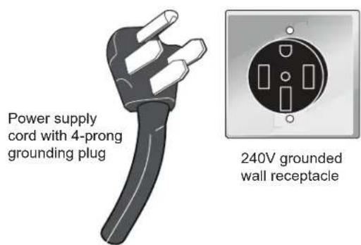
Plug the 4-prong range power cable into a properly grounded, 240V wall outlet.
text_image
Power supply cord with 4-prong grounding plug 240V grounded wall receptacleFig. 8
30" ELECTRIC FRONT CONTROL FREESTANDING INSTALLATION INSTRUCTIONS
6. Installing Power Cords (United States)
RISK OF FIRE OR ELECTRICAL SHOCK MAY OCCUR IF AN INCORRECT SIZE RANGE CORD KIT IS USED, THE INSTALLATION INSTRUCTIONS ARE NOT FOLLOWED OR STRAIN RELIEF BRACKET IS DISCARDED.
This appliance may be connected by means of a power supply cord. Use a power supply cord kit rated at 125/250 volts minimum, marked for use with ranges.
| Range Connection Opening Size Chart | |||
| Supply Cord Kit ampere rating information. See serial plate on range for kilowatt rating data. | |||
| See Serial Plate on Range for KW Rating | Cord Kit Ampere Rating | Diameter (inches) of Range connection Opening | |
| 120/240 Volts 120/208 Volts | Cord Kit | Permanent Wiring | |
| 8.8-16.5 KW 7.9-12.5 KW 16.6-22.5 KW 12.6-18.5 KW | 40/50 Amp 50 Amp | 1-3/8 in. 1-3/8 in. | 1-1/8 in. 1-3/8 in. |
Fig. 9
Cord must have either three (3) or four (4) conductors. Terminals on end of wires must be either closed loop or open-end spade lugs with upturned ends.
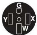
Required for new and remodeled installations
4-Wire Wall receptacle (14-50R)

Allowed for existing installations
3 Wire Wall receptacle (10-50R)
Fig. 10
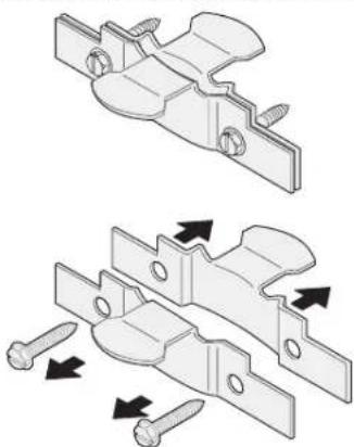
Cord must have strain relief properly installed.
natural_image
Technical illustration of two mechanical bracket assemblies with screw fasteners and directional arrows indicating assembly (no text or symbols)Fig. 11
Access the Terminal Block
- Remove the access cover and bracket from the back of the appliance. Keep all pieces and the screws.
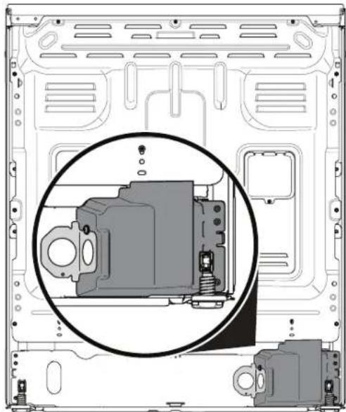
natural_image
Technical diagram of a mechanical assembly with a magnified inset showing internal components (no text or labels)Fig. 12
- Pull the cord terminals through the correct hole in the bracket included with the appliance.
- Connect the terminals to the terminal block as instructed for 3-wire, 4-wire, or permanent connections. See the next section for specific instructions for each connection.
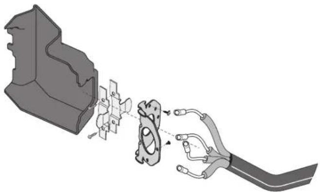
- Place the strain relief through the included bracket and tighten against the power cord.
- Replace the bracket and access cover on the appliance.
natural_image
Mechanical assembly diagram showing a clamping device interacting with a bracket (no text or symbols present)Fig. 13
30" ELECTRIC FRONT CONTROL FREESTANDING INSTALLATION INSTRUCTIONS
4-Wire Power Cord Connection (New branch-circuit or mobile home)
- Insert the end connectors for Line 1, Line 2 and Neutral and tighten securely to the terminal block. IMPORTANT NOTE: DO NOT LOOSEN the factory installed nut connections which secure the range wiring to the terminal block. Electrical failure or loss of electrical connection may occur if these nuts are loosened or removed.
- You must disconnect the ground strap. Remove the factory installed ground screw and plate to release the copper ground strap from the frame of the appliance. Cut and discard the copper ground strap and plate. Keep the ground screw.
- Connect the GREEN ground wire lead with the eyelet to the frame of the appliance with the ground screw using the same hole in the frame where the ground screw was originally installed.
- Follow the manufacturer's installation instructions supplied with the strain relief and install.
- Make sure all screws are tightened securely and replace the rear access cover.
3-Wire Power Cord Connection (Existing installations ONLY)
A ground strap is installed on this range which connects the center terminal of the terminal block (Neutral) to the range chassis. The ground strap is connected to the range by the center screw (see Fig. 15). The ground strap must not be removed unless National, State or Local Codes do not permit use of a ground strap.
NOTE: If the ground strap is removed for any reason, a separate ground wire must be connected to the separate ground screw attached to the range chassis and to an adequate ground source.
- Insert the end connectors for Line 1, Line 2 and Neutral and tighten securely to the terminal block. IMPORTANT NOTE: DO NOT LOOSEN the factory installed nut connections which secure the range wiring to the terminal block. Electrical failure or loss of electrical connection may occur if these 3 nuts are loosened or removed.
- Follow the manufacturer's installation instructions supplied with the strain relief and install.
- Make sure all connections are tightened securely and replace the rear access cover.
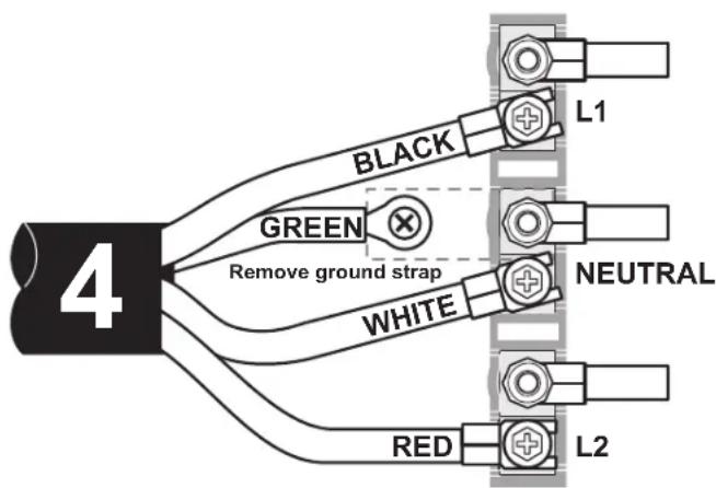
flowchart
graph TD
    A["4"] --> B["BLACK"]
    A --> C["GREEN"]
    A --> D["WHITE"]
    A --> E["RED"]
    B --> F["L1"]
    C --> G["NEUTRAL"]
    D --> H["L2"]
NOTE: Internal white wire not present on all models.
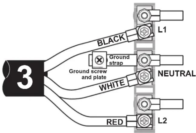
flowchart
graph TD
    A["3"] --> B["BLACK"]
    A --> C["Ground strap"]
    A --> D["Ground screw and plate"]
    A --> E["WHITE"]
    A --> F["RED"]
    B --> G["L1"]
    C --> H["NEUTRAL"]
    D --> I["L2"]
Fig. 15Fig. 14
NOTE: Internal white wire not present on all models.
30" ELECTRIC FRONT CONTROL FREESTANDING INSTALLATION INSTRUCTIONS
3-Wire and 4-Wire Permanent Connection
This appliance may be connected by means of permanent wiring.
When installing permanent wiring, do not leave excess wire in range compartment. Excess wire in the range compartment may not allow the rear access cover to be replaced properly and could create a potential electrical hazard if wires become pinched. Connect only as instructed. When using flexible conduit or range cable use flex connector or range cable strain relief.
- Strip insulation away from the ends of the permanent wiring for Line 1, Line 2, Neutral (also strip ground wire on 4-Wire Connections). Tighten all wire leads to the terminal block (Follow wire locations shown in Fig. 16). IMPORTANT NOTE: DO NOT LOOSEN the factory installed nut connections which secure the range wiring to the terminal block. Electrical failure or loss of electrical connection may occur if these nuts are loosened or removed.
- (4-Wire Permanent Connection ONLY) Disconnect the ground strap. Remove the factory installed ground screw and plate to release the factory installed copper ground strap from frame of the appliance. Cut and discard the copper strap from the terminal block. Keep the ground screw and ground plate.
- (4-Wire Permanent Connection ONLY) Connect the ground wire lead (Green) to the frame of the appliance using the ground screw & plate as shown in Fig. 17. Be sure to install using the same hole in the frame where the ground screw was originally installed.
- Follow the manufacturer's installation instructions supplied with the strain relief and install.
- Make sure all connections are tightened securely and replace the rear access cover.
NOTE: Non-terminated field wire compression connections must be set at 22 in./lbs. or greater. Always use 10 gauge wire or larger.
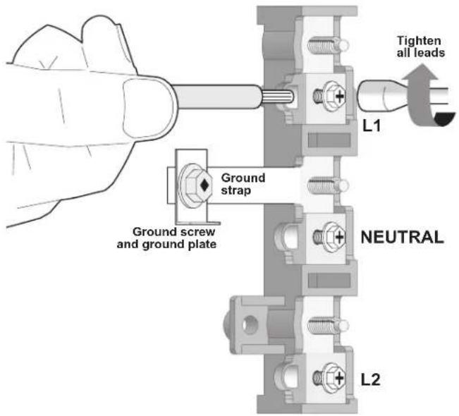
text_image
Tighten all leads L1 Ground strap Ground screw and ground plate NEUTRAL L2Fig. 16
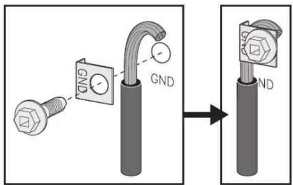
text_image
GND GND NDFig. 17
30" ELECTRIC FRONT CONTROL FREESTANDING INSTALLATION INSTRUCTIONS
7. Carefully Slide Range Into Final Location
Be sure to provide all the adequate clearances and dimensions before moving appliance into final location.
Carefully slide range into final position while inserting rear leveling leg into the anti-tip bracket. Make sure the power cord folds into the remaining open floor area behind the range. Be sure to check the level of the range.
Model and Serial Number Location
The serial plate is located on the front of the appliance, visible when the door is opened.
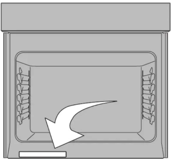
natural_image
Diagram of a storage or processing unit with internal compartments and a downward arrow indicating flow or movement (no text or symbols)Fig. 18
When ordering parts for or making inquires about your range, always be sure to include the model and serial numbers and a lot number or letter from the serial plate on your range.
Your serial plate also tells you the Kilowatt rating (power requirements) and Voltage ratings.
Care, Cleaning and Maintenance
Refer to the Use & Care Manual for cleaning instructions.
If removing the range is necessary for cleaning or maintenance, disconnect the electrical power supply. If the electrical supply is inaccessible, lift the unit slightly at the front and pull out away from the wall. Pull only as far as necessary to disconnect the electrical supply. Finish removing the unit for servicing and cleaning.
Before You Call for Service
Read the "Before You Call" and operating instruction sections in your Use & Care Manual. It may save you time and expense. The list includes common occurrences that are not the result of defective workmanship or materials in this appliance.
Refer to the warranty in your Use & Care Manual for our toll-free service number and address. Please call or write if you have inquiries about your range product and/or need to order parts.
natural_image
Collection of various hand tools including pliers, drill bit, tape measure, and hose (no text or labels visible)natural_image
Technical illustration of two mechanical bracket assemblies with screw fasteners and mounting holes (no text or symbols)Fig. 11
natural_image
Technical diagram of a mechanical assembly inside a server casing, showing internal components and mounting brackets (no text or labels)Fig. 12
natural_image
Mechanical assembly diagram showing a hand holding a bracket connected to a mechanical component with a spring-like part (no text or symbols visible)Fig. 13
natural_image
Diagram of a storage or oven with internal compartments and a downward arrow indicating flow or movement (no text or symbols)Fig. 18
natural_image
Collection of various hand tools including pliers, screwdriver, drill bit, tape measure, and hose (no text or symbols visible)natural_image
Technical illustration of two mechanical bracket assemblies with screw fasteners and directional arrows indicating assembly (no text or symbols)Fig. 11
Accéder au bornier
natural_image
Technical diagram of a computer chassis showing internal components and mounting brackets (no text or labels)Fig. 12
natural_image
Mechanical assembly diagram showing a hand holding a bracket connected to a mechanical component with a spring-like part (no text or symbols present)Fig. 13
INSTRUCTIONS D'INSTALLATION DE LA COMMANDE ÉLECTRIQUE FRONTALE DE 30 PO
natural_image
Diagram of a storage or oven with internal compartments and a downward arrow indicating flow or movement (no text or symbols)Fig. 18