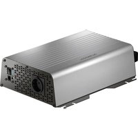
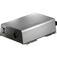
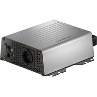
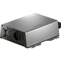
SinePower DSP 3512T - Battery charger DOMETIC - Free user manual and instructions
Find the device manual for free SinePower DSP 3512T DOMETIC in PDF.

| Product type | Pure sine wave inverter / DC-AC converter |
| Brand | Dometic |
| Model | SinePower DSP 3512T |
| Nominal input voltage | 12 V DC (range 10-16.5 V) |
| Output voltage | 230/240 V AC ± 3%, pure sine wave (THD < 3%) |
| Output frequency | 50/60 Hz ± 0.3 Hz |
| Nominal power | 3000 W |
| Peak power (2 s) | 6000 W |
| Efficiency | > 89% |
| No load consumption | 3.6 A |
| Standby consumption | < 0.2 A |
| Weight | 10.9 kg |
| Dimensions (L x H) | 326 x 490 mm |
| Protection | Over/under voltage, short circuit, overload, overheat, polarity reversal |
| Energy saving mode | Yes, adjustable via remote control or DIP switch |
| Cooling | Temperature and load controlled fan |
| Operating temperature | -20 °C to +60 °C |
| Permissible humidity | 0-95% non-condensing |
| Connections | Screw terminals (positive, negative, ground), 230 V input/output, remote control, CI/LIN-BUS |
| Maintenance | Clean with a damp cloth, do not use harsh detergents |
| Warranty | Legal manufacturer's warranty |
| Optional accessories | Remote control (ref. 9600002564), energy monitor (ref. 9600002565) |
| Certifications | EU declaration of conformity available at dometic.com |
Frequently Asked Questions - SinePower DSP 3512T DOMETIC
User questions about SinePower DSP 3512T DOMETIC
0 question about this device. Answer the ones you know or ask your own.
Ask a new question about this device
Download the instructions for your Battery charger in PDF format for free! Find your manual SinePower DSP 3512T - DOMETIC and take your electronic device back in hand. On this page are published all the documents necessary for the use of your device. SinePower DSP 3512T by DOMETIC.
USER MANUAL SinePower DSP 3512T DOMETIC
natural_image
Technical diagram showing a mechanical component with a pencil inserted, labeled 'A' and dimension '20mm' (no text or symbols beyond labels)B
natural_image
Technical line drawing of a heat exchanger or cooling unit with cooling fins and mounting points (no text or symbols)
A
C
DSP 35xxT
natural_image
Two technical illustrations of an electronic device with wiring and a van, no text or symbols present
DSP 35xxT
10
A

B
C
D
natural_image
Line drawing of an electronic device with a coiled cable and terminal connector (no text or symbols)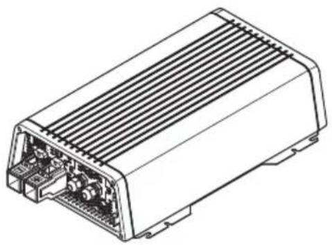
natural_image
Technical line drawing of an electronic device housing with internal components (no text or symbols)DSP1312T, DSP1324T, DSP1812T, DSP1824T, DSP2312T, DSP2324T, DSP3512T, DSP3524T
Sine wave inverter
Installation and Operating Manual.....3
Please read this instruction manual carefully before installation and first use, and store it in a safe place. If you pass on the product to another person, hand over this instruction manual along with it.
Table of contents
1 Explanation of symbols....4
2 General safety instructions ....4
3 Scope of delivery 8
4 Accessories....8
5 Target group for this manual. 8
6 Intended use 9
7 Technical description 9
8 Fitting the inverter....12
9 Connecting the inverter .....14
10 Using the inverter .....17
11 Cleaning and caring for the inverter.... 20
12 Troubleshooting....21
13 Warranty 22
14 Disposal.... 22
15 Technical data 23
1 Explanation of symbols

DANGER!
Safety instruction: Failure to observe this instruction will cause fatal or serious injury.

WARNING!
Safety instruction: Failure to observe this instruction can cause fatal or serious injury.

NOTICE!
Failure to observe this instruction can cause material damage and impair the function of the product.

NOTE
Supplementary information for operating the product.
2 General safety instructions
2.1 General safety
The manufacturer accepts no liability for damage in the following cases:
• Faulty assembly or connection
- Damage to the product resulting from mechanical influences and excess voltage
• Alterations to the product without express permission from the manufacturer
- Use for purposes other than those described in the operating manual
Note the following basic safety information when using electrical devices to protect against:
- Electric shock
- Fire hazards
•Injury
2.2 General safety

DANGER!
- In the event of fire, use a fire extinguisher which is suitable for electrical devices.

WARNING!
- Only use the device as intended.
- Ensure that the red and black terminals never come into contact.
- Disconnect the device from the mains:
– Before cleaning and maintenance
- If you disassemble the device:
- Detach all connections
- Make sure that no voltage is present at any of the inputs and outputs
- The device may not be used if the device itself or the connection cable are visibly damaged.
- If this power cable for this device is damaged, it must be replaced by the manufacturer, customer service or a similarly qualified person in order to prevent safety hazards.
- This device may only be repaired by qualified personnel. Inadequate repairs may cause serious hazards.
- This device can be used by children aged 8 years or over, as well as by persons with diminished physical, sensory or mental capacities or a lack of experience and/or knowledge, providing they are supervised or have been taught how to use the device safely and are aware of the resulting risks.
• Electrical devices are not toys.
Always keep and use the appliance out of the reach of children.
- Children must be supervised to ensure that they do not play with the device.

NOTICE!
- Before start-up, check that the voltage specification on the type plate is the same as that of the power supply.
- Ensure that other objects cannot cause a short circuit at the contacts of the device.
- Never pull the plug out of the socket by the connection cable.
- Store the device in a dry and cool place.
2.3 Safety when installing the device

DANGER!
- Never mount the device anywhere where there is a risk of gas or dust explosion.

CAUTION!
- Ensure that the device is standing firmly.
The device must be set up and fastened in such a way that it cannot tip over or fall down.

NOTICE!
- Do not expose the device to a heat source (such as direct sunlight or heating). Avoid additional heating of the device in this way.
- Set up the device in a dry location where it is protected against splashing water.
2.4 Safety when connecting the device electronically

DANGER! Danger of electrocution
- If you are working on electrical systems, ensure that there is somebody close at hand who can help you in emergencies.

WARNING!
• Make sure that the lead has a sufficient cross-section.
- Lay the cables so that they cannot be damaged by the doors or the bonnet.
Crushed cables can lead to serious injury.

CAUTION!
- Lay the cables so that they cannot be tripped over or damaged.

NOTICE!
- Use ductwork or cable ducts if it is necessary to lay cables through metal panels or other panels with sharp edges.
- Do not lay the 230 V mains cable and the 12 V DC cable in the same duct.
- Do not lay the cable so that it is loose or heavily kinked.
- Fasten the cables securely.
- Do not pull on the cables.
2.5 Operating the device safely

DANGER! Danger of electrocution
- Do not touch exposed cables with your bare hands.
WARNING!
- Only use the device in closed, well-ventilated rooms.
CAUTION!
- Do not operate the device
– In salty, wet or damp environments
– In the vicinity of corrosive fumes
– In the vicinity of combustible materials
– In areas where there is a danger of explosions.
- Before starting the device, ensure that the power supply line and the plug are dry.
- Always disconnect the power supply when working on the device.
- Please observe that parts of the device may still conduct voltage even if the fuse has blown.
- Do not disconnect any cables when the device is still in use.

NOTICE!
- Make sure the air inlets and outlets of the device are not covered.
- Ensure good ventilation.
| 3 | S | c | o | p | e | o | f | d |
No. in

Designation
1 Sine wave inverter
2 Connection cable with safety coupling (for 230 V\~ output)
3 Connection cable with safety plug (for 230 V\~ supply)
- Operating manual
| 4 | A | c | c | e | s | s | o | r | i |
Designation Ref. no.
Remote control 9600002564
Energy monitor 9600002565
5 Target group for this manual
The electrical installation (chapter "Connecting the inverter" on page 14) is intended for professionals who are familiar with the applicable regulations of the country in which the equipment is to be installed and/or used.
All other chapters are intended for the users.
6 Intended use

WARNING!
Never use the inverter on vehicles where the positive terminal of the battery is connected to the chassis.
The wave inverter converts direct current into a 230 – 240 V AC supply of 50 Hz or 60 Hz:
• 12 V=== DSP1312T, DSP1812T, DSP2312T, DSP3512T
• 24 V---: DSP1324T, DSP1824T, DSP2324T, DSP3524T
7 Technical description
The inverters can be operated wherever a DC connection is available:
• 12 V=== DSP1312T, DSP1812T, DSP2312T, DSP3512T
• 24 V---: DSP1324T, DSP1824T, DSP2324T, DSP3524T
The light-weight and compact construction of this device allows for easy installation in mobile homes, commercial vehicles or motor and sailing yachts.
The output voltage corresponds to the household voltage from the socket (pure sine wave, THD < 3 %).
Please observe the values for constant output power and peak output power as indicated in chapter "Technical data" on page 23. Never connect devices that have a higher power requirement.

NOTE
Note when connecting devices with an electrical drive (such as power drills and refrigerators), that they often require more power than is indicated on the type plate.
The inverter has various protective mechanisms.
- Overvoltage shutdown: The inverter shuts itself off when the voltage exceeds the cut-off value. It restarts when the voltage returns to the restart value.
- Undervoltage shutdown: The inverter shuts itself off when the voltage sinks below the cut-off value. It restarts when the voltage rises to the restart value.
- Excess temperature shutdown: The inverter switches off when the temperature inside the device or the temperature on the cooling element exceeds a cut-off value. It restarts when the voltage rises to the restart value.
- Overloading and short circuit shutdown: The LED on the inverter indicates an operating fault when an excess load is connected or a short circuit has occurred. The fuse in the device must be pressed in again by hand after it is triggered by excess current.

NOTE
The individual values are found in the chapter "Technical data" on page 23.
The inverter can be operated in the following network configurations:
•TN network:
The neutral conductor of the inverter is grounded. A downstream safety switch (RCD) must be installed.
- IT network:
Both phases are insulated. This is suitable for operating one load. If more than one load will be connected a protection plan has to be set up (e.g. insulation monitor).
The network configuration is set via a DIP switch at the device.
The inverters DSP13xxT, DSP18xxT, DSP23xxT have a connection cable with socket and plug. The inverter DSP35xxT is directly connected at the terminals via the PG glands.
Due to the phase synchronisation the inverter adapts to the phase of the AC input voltage. Thereby voltage peaks are prevented when switching from battery to mains.
The inverter is suitable for operating sensitive consumers because the output voltage is a pure sinus wave.
The inverter is fitted with a priority circuit. If an external 230 V\~ voltage is available, this will have priority. If no external 230 V\~ voltage is connected, then the connected battery will be used as the power supply.
The inverter can be switched to an energy-saving mode to prevent the connected battery from discharging too quickly.
The inverter can be turned on or off using the remote control (accessory).
Additionally, the inverter can be controlled using the energy monitor (accessory).
7.1 Control elements
No. in

Description Description
1 Main switch 0: Switches the device permanently off
I: Switches the device permanently on
II: The device can be switched on or off via a remote control (accessory)
2 Status LED See chapter "Status indications" on page 17
3 Fuse Protects the inverter from overload.
The fuse can be pressed in again once it has triggered.
4 Dip switch Makes settings on the inverter
See chapter "Configuring the inverter" on page 18
7.2 Connections

NOTE
The version for continental Europe is depicted.
No. in
fig. 2
Description
5 AC input (DSP35xxT: PG fitting)
6 AC output (DSP35xxT: PG fitting)
7 Ground terminal (Earthing on the vehicle bodywork)
8 Positive terminal
9 Negative terminal
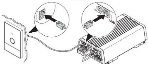
10 CI/LIN BUS connections (LINA)
11 Remote control connection (LINB)
12 Connection of remote switch
13 Fan (backside)
8 Fitting the inverter

NOTE
Before fitting the inverter, you should connect all cables because all connections are freely accessible.
8.1 Tools required
For the electrical connection you will need the following tools:
- Crimping tool
- 3 multi-coloured, flexible connection cables. Determine the necessary thickness from the table in chapter "Connecting the inverter" on page 14.
• Cable lugs and conductor sleeves
For fastening you will require the following tools:
- Machine bolts (M4) with washers and self-locking nuts or
- self-tapping screws or wood screws.
8.2 Mounting instructions
When selecting the installation location, observe the following instructions:
- The inverter can be mounted horizontally or vertically.
- The inverter must be installed in a place that is protected from moisture.
- The inverter may not be installed in the presence of flammable materials.
- The inverter may not be installed in a dusty environment.
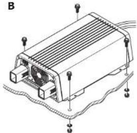
- The place of installation must be well ventilated. A ventilation system must be available for installations in small, enclosed spaces. The minimum clearance around the inverter must be at least 5 cm (fig. 3).
- The ventilation holes on the front and back of the inverter must remain clear.
- For ambient temperatures higher than 40 °C (such as in engine or heating compartments, or direct sunlight), the inverter may shut down although the connected load is below the rated load (derating).
- The device must be installed on a level and sufficiently sturdy surface.

NOTICE!
Before drilling any holes, make sure that no electrical cables or other parts of the vehicle can be damaged by drilling, sawing and filing.
8.3 Mounting the inverter
▶ Mount the inverter as shown (fig. 4).
9 Connecting the inverter
9.1 General instructions

WARNING!
- The inverter may only be connected by a qualified workshop. The following information is intended for technicians who are familiar with the guidelines and safety precautions to be applied.
- Never use the inverter on vehicles where the positive terminal of the battery is connected to the chassis.
-
If you do not fit a fuse to the positive cable, the cables can overload, which might result in a fire.
-
When installed in vehicles or boats, the inverter must be connected to the chassis or earth.
- When setting up a socket distribution circuit (mains setup), comply with the applicable regulations.
- Only use copper cables.
- Keep the cables as short as possible (< 1 m).
- For grounding use a cable with a minimum cross section of 4mm^2 .
- Keep to the specified cable cross section and fit a cable fuse (fig. 6 1) as close to the battery as possible on the positive cable (see the table).
| Device | Required cable cross section | Cable fuse |
| DSP1312T 35 mm ^2 200 A | ||
| DSP1324T 25 mm ^2 150 A | ||
| DSP1812T 50 mm ^2 250 A | ||
| DSP1824T 25 mm ^2 150 A | ||
| DSP2312T 70 mm ^2 300 A | ||
| DSP2324T 35 mm ^2 200 A | ||
| DSP3512T | 2 x 50 mm ^2 | 2 x 250 A |
| DSP3524T 50 mm ^2 250 A |
9.2 Connecting the inverter

WARNING!
Before connecting the AC output cable, make sure the inverter is switched off at the main switch.

NOTICE!
Make sure that you do not reverse the polarity. Incorrect polarity can damage the inverter.

NOTE
Tighten the nuts and bolts to a maximum torque of 15 Nm. Loose connections may cause overheating.
▶Connect the inverter as shown:
- Connecting the battery: fig. 5 and fig. 6
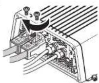
- Connecting the ground terminal fig. 7
- Connecting the 230 V power cable: fig. 8 (INPUT)
- Connecting the 230 V output cable: fig. 8 (OUTPUT)
9.3 Connecting multiple appliances
The device is equipped at delivery with galvanic isolation. For the safe operation of multiple appliances, it is essential that a circuit breaker (residual current circuit breaker) is built into the socket distribution circuit.
▶ Install a residual current circuit breaker in the socket distribution circuit.
9.4 Connecting the remote control (accessory)

NOTICE!
Only plug in the connection to the remote control in the remote port. The device can be damaged by connecting it incorrectly.
▶ Connect the remote control as shown (fig. 9).
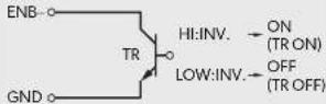
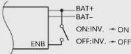
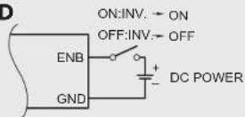
9.5 Connecting external switch to turn device on and off

NOTE
Use cables with a cable cross section of 0.25 - 0.75 mm ^2 .
You can use the following as an external switch:
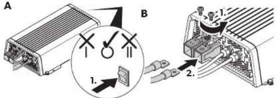
• External switch, voltage supply from the inverter: fig. 10 A
• Control unit with relay or transistor circuit (TR): fig. 10 B
- External switch with voltage supply from the battery (BAT) of the vehicle: fig. 10C
- External switch with its own voltage supply (DC POWER) e.g. from the ignition: fig. 10D
▶ Set the main switch (fig. 2 1) to "OFF".
▶ Make sure that the connection for the remote control (fig. 2 11) is not assigned.
▶ Set the main switch (fig. 2 1) to "REMO.".
▶ Connect the external on/off switch with the connection cable to the terminal (fig. 212).
9.6 Connecting the fault display relay
You can install a relay which monitors whether the 230 V input is connected. Thereby you can, for example, implement an immobiliser so that the vehicle cannot be started when the 230 V input is connected.
▶ Connect the relay as shown (fig. 11):
- NO: normally open contact
- COM: common contact
- NC: normally closed contact
Relay specification:
| Maximum voltage Load | Current consumptionNO NC | ||
| 250 V~ | Ohmic | 0.5 A | 0.5 A |
| 12 V/24 V== | Ohmic | 1 A | 1 A |
10 Using the inverter
10.1 Switching on the inverter
▶ Set the main switch (fig. 2 1) of the inverter as follows:
- “0”: to switch the inverter permanently off
- “ I”: to switch the inverter permanently on
- "Il": to switch the inverter on and off with a remote control (accessory)
▶The inverter performs a self-test when starting.
√ After the self-test is completed successfully, the LED lights up blue (fig. 2 2).
10.2 Status indications
The blue LED (fig. 2 2) shows the operating condition of the inverter.
Display Input voltage
| Constantly lit Normal mode | |
| Long flash, short interruption | Inverter overheated/Overload |
| Quick flash | Overvoltage/Undervoltage |
| Short flash, long interruption | Insulation monitor has shut down the inverter |
| Off | Other fault |
The inverter switches off if:
- The battery voltage drops below 10 V (12 V--- connection) or 20 V (24 V--- connection).
- The battery voltage exceeds 16.5 V (12 V--- connection) or 33 V (24 V--- connection).
• The inverter is overloaded.
• The inverter overheats.
▶ If this happens, shut down the inverter with the main switch (fig. 2 1).
▶ Check that the inverter is sufficiently ventilated and that the ventilation grilles are unimpeded.
▶ Wait 5 – 10 minutes and switch the inverter on again without any electric consumers.
10.3 Switching to energy-saving mode

NOTE
The energy-saving mode can be set with a remote control only.
10.4 Configuring the inverter
You can adjust the device using the DIP switch (fig. 2 4).
Defining settings
Using the S1 dip switch you can define whether the parameter of the setting should be made using the connection of a CI BUS capable control panel or the dip switches.
| Dip switch | |
| Parameter S1 | |
| Remote control connection Off | |
| Dip switch On | |
Setting the mains voltage
You can set the mains voltage using the S2 dip switch.
| DIP switch | |
| Mains voltage S2 | |
| 230V/50Hz Off | |
| 240V/60Hz On | |
Switching to energy-saving mode
You can set the energy-saving mode using the S3 and S4 dip switches. In this way, the battery you connect to the inverter is not discharged as quickly.
The inverter operates in energy-saving mode as long as the required power is below the set level. If the required power exceeds the set level, the inverter works in normal mode.
The values to be set on your inverter can be found in the following table:
| Energy-saving mode | DIP switch |
| S3 S4 | |
| Saving mode activated when load < 45 W | Off Off |
| Normal mode activated when load > 45 W | |
| Saving mode activated when load < 1 W | On Off |
| Inverter shuts automatically down after operation20 min in saving mode | |
| Normal mode activated when load > 1 W | |
| Saving mode activated when load < 1 W | Off On |
| Normal mode activated when load > 1 W | |
| Saving mode activated when load < 45 W | On On |
| Inverter shuts automatically down after operation20 min in saving mode | |
| Normal mode activated when load > 45 W |
Setting net configuration
Using the S5 dip switch you can define in which net configuration the inverter shall operate.
| Parameter S5 | Dip switch |
| TN grid | Off |
| An external downstream circuit breaker (RCD) is necessary. | |
| IT grid | On |
| Operation with one load only or installation of an external insulation monitor. | |
| National standards shall apply! |
11 Cleaning and caring for the inverter

NOTICE!
Do not use sharp or hard objects or cleaning agents for cleaning as these may damage the product.
▶Occasionally clean the product with a damp cloth.
12 Troubleshooting

WARNING!
Do not open the device. You risk sustaining an electric shock by doing this.

NOTE
If you have detailed questions on the specifications of the inverter please contact the manufacturer (addresses on the back of the instruction manual).
The LED (fig. 2 2) indicates the fault:
LED display Cause Remedy
| Quick flash Input voltage is too high Check the input voltage and reduce it. | |
| Input voltage too low The battery needs recharging.Check the cables and connections. | |
| 2 s lit, short interruption | Overheating Switch off the inverter and the consumer.Wait 5 to 10 minutes and switch the inverter on again without any electric consumers.Reduce the load and make sure the inverter has better ventilation. Then switch the con-sumer back on. |
| Excessive load Switch off the inverter and remove the consumer.Then switch the inverter back on without the consumer. If no excessive load is now shown, then there is a short circuit in the consumer or the total load was higher than the power specified on the data sheet.Check the cables and connections.Press in the fuse in the device again by hand. | |
Off Other fault Contact the service.
13 Warranty
The statutory warranty period applies. If the product is defective, please contact the manufacturer's branch in your country (see the back of the instruction manual for the addresses) or your retailer.
For repair and guarantee processing, please include the following documents when you send in the device:
• A copy of the receipt with purchasing date
- A reason for the claim or description of the fault
14 Disposal
▶ Place the packaging material in the appropriate recycling waste bins wherever possible.
If you wish to finally dispose of the product, ask your local recycling centre or specialist dealer for details about how to do this in accordance with the applicable disposal regulations.
15 Technical data
The following technical data applies to all inverters:
| Output voltage: | 230/240 V~ ± 3 %, pure sine wave (THD < 3 %) |
| Output frequency: 50/60 Hz ± 0,3 Hz | |
| Heat dissipation: temperature and load controlled fan | |
| Ambient temperature at operation: -20 °C to | +60 °C |
| Ambient temperature for storage: -30 °C to | +70 °C |
| Power control: ≥40 °C | |
| Bypass relay: 16 A/250 V~ | |
| Bypass switching with voltage synchronisation: | <20 ms |
| Air humidity: 0 – 95 %, non-condensing | |
| Testing/certification: |  |
| DSP1312T | DSP1812T D | SP1324T DS | P1824T | |
| Ref. no.: 9600002551 9600 | 002553 96000 | 02552 960000 | 2554 | |
| Rated input voltage: 12 V---24 V--- | ||||
| Input voltage range: | 10-16.5 V--- | 20-33 V--- | ||
| Rated load: | 1200 W | 1800 W | 1200 W | 1800 W |
| Maximum power for 10 min: | 1300 W | 1800 W | 1300 W | 1800 W |
| Maximum power for 3 min: | 1380 W | 2070 W | 1380 W | 2070 W |
| Surge power for 2 s: | 2400 W | 3600 W | 2400 W | 3600 W |
| Idle current consumption: | 2.5 A | 2.5 A | 1.3 A | 1.3 A |
| Standby current consumption at rated voltage: | <0.2 A | <0.2 A | <0.1 A | <0.1 A |
| Efficiency: | >89 % | >90 % | ||
| Power adjustment at input voltages between 10.0 V and 10.5 V: | 1020 W | 1530 W | 1020 W | 1530 W |
| Power adjustment at temperatures above 40 °C: | 1.75 % of rated load per degree above 40 °C | |||
| Dimensions W x L x H: | fig. 15 | |||
| Weight: | 4.8 kg | 6.1 kg | 4.8 kg | 6.1 kg |
| DSP2312T D | SP3512T DSP | 2324T DSP35 | 24T | |
| Ref. no.: 9600002555 9600 | 002557 96000 | 02556 960000 | 2558 | |
| Rated input voltage: 12 V---24 V--- | ||||
| Input voltage range: | 10-16.5 V--- | 20-33 V--- | ||
| Rated load: | 2000 W | 3000 W | 2000 W | 3000 W |
| Maximum power for 10 min (UIN>12,5 V): | 2300 W | 3500 W | 2300 W | 3500 W |
| Maximum power for 3 min (UIN>10,5 V): | 2300 W | 3500 W | 2300 W | 3500 W |
| Surge power for 2 s: | 4000 W | 6000 W | 4000 W | 6000 W |
| Idle current consumption: | 2.8 A | 3.6 A | 1.4 A | 1.8 A |
| Standby current consumption at rated voltage: | <0.2 A | <0.2 A | <0.15 A | <0.15 A |
| Efficiency: | >89 % | >90 % | ||
| Power adjustment at input voltages between 10.0 V and 10.5 V: | 1700 W | 2600 W | 1700 W | 2600 W |
| Power adjustment at temperatures above 40 °C: | 1.75 % of rated load per degree above 40 °C | |||
| Dimensions W x L x H: | fig. 15 | |||
| Weight: | 6.6 kg | 10.9 kg | 6.6 kg | 10.9 kg |
Protective devices
| 12 V 24 V | ||
| Input: Undervoltage, reverse polarity (internal fuse) | ||
| AC output: Overvoltage, short circuit, overload | ||
| AC input: 16 A circuit breaker | ||
| Temperature: Shutdown | ||
| Short circuit protection: Yes, lpk | ||
Overvoltage shutdown
| Device | Overvoltage | |
| Shutdown Restart | ||
| DSP1312T, DSP1812T, DSP2312T, DSP3512T | 16.5 V 15.5 V | |
| DSP1324T, DSP1824T, DSP2324T, DSP3524T | 33 V 31 V | |
Undervoltage shutdown
| Device | Undervoltage | |
| Shutdown Restart | ||
| DSP1312T, DSP1812T, DSP2312T, DSP3512T | 10 V | 12 V |
| DSP1324T, DSP1824T, DSP2324T, DSP3524T | 20 V | 24 V |
For the current EU declaration of conformity for your device please refer to the respective product page on dometic.com or contact the manufacturer directly (see back page).
7 Description technique
- NC (Normally Closed): contacto de reposo