USER MANUAL MED7020RW MAYTAG
ELECTRIC DRYER PRODUCT GUIDE GUIDE D'UTILISATION DE LA SÉCHEUSE ÉLECTRIQUE GUÍA DE PRODUCTO DE LA SECADORA ELÉCTRICA
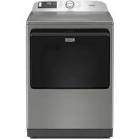
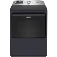
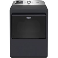
natural_image
White Maytag washing machine with control panel and digital display (no visible text or symbols on main body)
Table of Contents
OWNER'S MANUAL....3
DRYER SAFETY 3
Dryer Safety 3
Internet Connectivity Guide for Connected
Appliances Only 5
DRYER MAINTENANCE AND CARE 7
Cleaning the Dryer Location 7
Cleaning the Dryer Interior 7
Removing Accumulated Lint....7
Cleaning the Lint Screen 7
Changing the Drum Light (on some models) 8
Check Your Vent System for Good Airflow 8
Maintain Good Airflow....8
Nonuse, Storage, and Moving Care 8
INSTALLATION REQUIREMENTS....9
Tools and Parts 9
Location Requirements 10
Electrical Requirements – U.S.A. 11
Electric Requirements – Canada 12
INSTALLATION 13
Install Leveling Legs 13
Electrical Installation – U.S.A. 13
Venting Requirements.... 18
Plan Vent System 19
Install Vent System.... 20
Connect Inlet Hoses 20
Connect Vent 21
Level Dryer....21
Complete Installation Checklist 22
QUICK START GUIDE.... 23
Quick Start Guide....23
CYCLE GUIDE....26
Dryer Cycle Guide.... 26
TROUBLESHOOTING....28
Trouble shooting....28
Índice
MANUAL DEL PROPIETARIO....65
Your safety and the safety of others are very important.
We have provided many important safety messages in this manual and on your appliance. Always read and obey all safety messages.
This is the safety alert symbol.
This symbol alerts you to potential hazards that can kill or hurt you and others.
All safety messages will follow the safety alert symbol and either the word "DANGER" or "WARNING." These words mean:
You can be killed or seriously injured if you don't immediately follow instructions.
You can be killed or seriously injured if you don't follow instructions.
All safety messages will tell you what the potential hazard is, tell you how to reduce the chance of injury, and tell you what can happen if the instructions are not followed.
WARNING — “Risk of Fire”
- Clothes dryer installation must be performed by a qualified installer.
- Install the clothes dryer according to the manufacturer's instructions and local codes.
- Do not install a clothes dryer with flexible plastic venting materials or flexible metal (foil type) duct. If flexible metal duct is installed, it must be of a specific type identified by the appliance manufacturer as suitable for use with clothes dryers. Flexible venting materials are known to collapse, be easily crushed, and trap lint. These conditions will obstruct clothes dryer airflow and increase the risk of fire.
- To reduce the risk of severe injury or death, follow all installation instructions.
- Save these instructions.
IMPORTANT SAFETY INSTRUCTIONS
WARNING: To reduce the risk of fire, electric shock, or injury to persons when using your appliance, follow basic precautions, including the following:
- Read all instructions before using the appliance.
■ Do not dry articles that have been previously cleaned in, washed in, soaked in, or spotted with gasoline, dry-cleaning solvents, or other flammable or explosive substances, as they give off vapors that could ignite or explode.
■ Risk of Suffocation and Injury from Entrapment: Do not allow children to play on or in the appliance. Close supervision of children is necessary when the appliance is used near children.
■ Before the appliance is removed from service or discarded, remove the door to the drying compartment.
■ Do not reach into the appliance if the drum is moving.
■ Do not install or store this appliance where it will be exposed to the weather.
■ Do not tamper with controls.
- Do not repair or replace any part of the appliance or attempt any servicing unless specifically recommended in the user-maintenance instructions or in published user-repair instructions that you understand and have the skills to carry out.
■ Do not use fabric softeners or products to eliminate static unless recommended by the manufacturer of the fabric softener or product.
■ Do not use heat to dry articles containing foam rubber or similarly textured rubber-like materials.
■ Clean lint screen before or after each load.
- Keep area around the exhaust opening and adjacent surrounding areas free from the accumulation of lint, dust, and dirt.
■ The interior of the appliance and exhaust duct should be cleaned periodically by qualified service personnel.
■ Do not place items exposed to cooking oils in your dryer. Items contaminated with cooking oils may contribute to a chemical reaction that could cause a load to catch fire. To reduce the risk of fire due to contaminated loads, the final part of a tumble dryer cycle occurs without heat (cool down period). Avoid stopping a tumble dryer before the end of the drying cycle unless all items are quickly removed and spread out so that the heat is dissipated.
Do not use replacement parts that have not been recommended by the manufacturer (e.g. parts made at home using a 3D printer).
■ See the Installation Instructions for grounding requirements and installation.
■ Do not install a booster fan in the exhaust duct.
NOTE: The booster fan warning does not apply to clothes dryers intended to be installed in a multiple clothes dryer system, with an engineered exhaust duct system that is installed per the clothes dryer manufacturer's guidelines.
SAVE THESE INSTRUCTIONS
IMPORTANT SAFETY INSTRUCTIONS
WHEN DISCARDING OR STORING YOUR OLD CLOTHES DRYER, REMOVE THE DOOR.
SAVE THESE INSTRUCTIONS
Internet Connectivity Guide for Connected Appliances Only
IMPORTANT: Proper installation of your appliance prior to use is your responsibility. Be sure to read and follow the installation instructions that came with your appliance.
Connectivity requires Wi-Fi and account creation. App features and functionality are subject to change. Data rates may apply. Once installed, launch the app. You will be guided through the steps to set up a user account and to connect your appliance.
You Will Need:
A home wireless router supporting Wi-Fi, 2.4 Ghz with WPA2 security. If you are unsure of your router's capabilities, refer to the router manufacturer's instructions.
■ The router to be on and have a live internet connection.
■ The 10-character SAID code for your appliance. The SAID code is either printed on a label on the appliance or found on the LCD screen.
Federal Communications Commission (FCC) Compliance Notice
This device complies with Part 15 of the FCC Rules. Operation is subject to the following two conditions:
-
This device may not cause harmful interference, and
-
This device must accept any interference received, including interference that may cause undesired operation.
Changes or modifications not expressly approved by the party responsible for compliance could void the user's authority to operate the equipment.
Industry Canada (IC) Compliance Notice
This Device complies with Industry Canada License-exempt RSS standard(s). Operation is subject to the following two conditions:
- This device may not cause interference.
- This device must accept any interference, including interference that may cause undesired operation of the device.
Under Industry Canada regulations, this radio transmitter may only operate using an antenna of a type and maximum (or lesser) gain approved for the transmitter by Industry Canada. To reduce potential radio interference to other users, the antenna type and its gain should be so chosen that the equivalent isotropically radiated power (e.i.r.p.) is not more than that necessary for successful communication.
To comply with FCC and Industry Canada RF radiation exposure limits for general population, antenna(s) used for this transmitter must be installed such that a minimum separation distance of 20 cm is maintained between the radiator (antenna) and all persons at all times and must not be co-located or operating in conjunction with any other antenna or transmitter.
If this equipment does cause harmful interference to radio or television reception, which can be determined by turning the equipment off and on, the user is encouraged to try to correct the interference by one of the following measures:
■ Reorient or relocate the receiving antenna.
■ Increase the separation between the equipment and receiver.
■ Connect the equipment into an outlet on a circuit different from that to which the receiver is connected.
■ Consult the dealer or an experienced radio/TV technician for help.
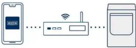
Connecting your front load smart appliance
NOTE: You may also go to www.maytag.com/connect for further instructions.
- In the app, select your network and enter your password.
TIP: If your home router has a choice of frequency bands, be sure to use the 2.4 GHz band router name.
- Download the Maytag™ app and create an account.

- Select ADD APPLIANCE.
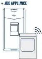
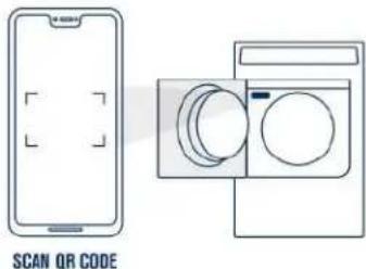
- Scan the QR code.
TIP: Find the QR code on the appliance label or manually enter the SAID and MAC.
- Select your product type and model number.
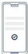
CONFIRM APPLIANCE INFORMATION
- Press and quickly release the WiFi Connect button on the appliance.
TIP: Do NOT hold the button, this will put the appliance in wrong mode. If your appliance says to "Hold 3 sec.", please ignore.

natural_image
Pure electrical circuit lines without any symbols
flowchart
graph LR
    A["手机"] --> B["路由器"]
    B --> C["电脑"]
    style A fill:#f9f,stroke:#333
    style B fill:#ccf,stroke:#333
    style C fill:#cfc,stroke:#333
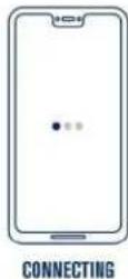
- A screen will appear that says "CONNECTING". These 4 steps can take up to 2 minutes to complete.
TIP: During this process, lights on the appliance will blink. This is normal. Once the appliance is connected, it will end on a solid white light.
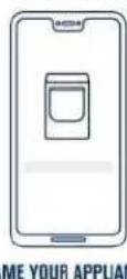
- Name your appliance and start using the remote features.
TIP: Remember to press the "Remote Enable" button when using these features.
DRYER MAINTENANCE AND CARE
Cleaning the Dryer Location
WARNING
Explosion Hazard
Keep flammable materials and vapors, such as gasoline, away from dryer.
Do not dry anything that has ever had anything flammable on it (even after washing).
Place dryer at least 18 inches (460 mm) above the floor for a garage installation.
Failure to do so can result in death, explosion, or fire.
Keep dryer area clear and free from items that would block the airflow for proper dryer operation. This includes clearing piles of laundry in front of the dryer.
Cleaning the Dryer Interior
To clean dryer drum:
- Use nonflammable cleaner or a mild hand dish detergent mixed at a low concentration with very warm water, and rub with a soft cloth.
■ Rinse well with a wet sponge or towel.
■ Tumble a load of clean clothes or towels to dry drum. OR
- Use a microfiber cloth and very warm water in a spray bottle clean the drum and a second microfiber towel to dry.
NOTE: Garments that contain unstable dyes, such as denim blue residue buildup.
jeans or brightly colored cotton items, may discolor the rear of the dryer interior. These stains are not harmful to your dryer and will not stain future loads of clothes. Dry unstable dye items inside 10 to avoid transfer of dye.
Removing Accumulated Lint
From inside the dryer cabinet:
Lint should be removed every 2 years, or more often, depending on dryer usage. Cleaning should be done by a qualified appliance service or ventilation system cleaner.
From the exhaust vent:
Lint should be removed every 2 years, or more often, depending on dryer usage.
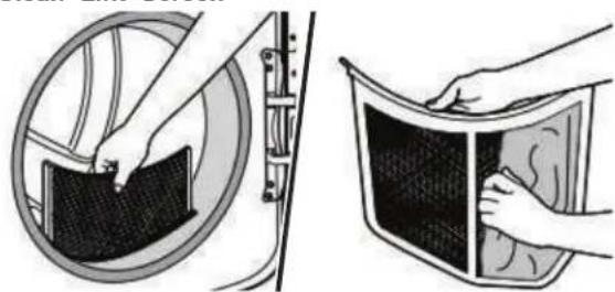
Cleaning the Lint Screen
Every load cleaning:
The lint screen may be located either in the door opening or the top of the dryer depending on model. A screen blocked by lint can increase drying time.
To clean:
- Remove the lint screen. If necessary, press the tab to release and open the lint screen. Roll lint off the screen with your fingers. Do not rinse or wash screen to remove lint. Wet lint is hard to remove.
- Push the lint screen firmly back into place.
IMPORTANT:
■ Do not run the dryer with the lint screen loose, damaged, blocked, or missing. Doing so can cause overheating and damage to both the dryer and fabrics.
If lint falls off the screen into the dryer during removal, check the exhaust hood and remove the lint. See "Venting Requirements" in the Installation Instructions.
■ Clean space where lint screen is located, as needed. Using a vacuum, gently remove any lint that has accumulated outside of the lint screen.
As-needed cleaning:
Laundry detergent and fabric softener residue can build up on the lint screen. This buildup can cause longer drying times for your clothes, or cause the dryer to stop before your load is completely dry. The screen is probably clogged if lint falls off while the screen is in the dryer. Clean the lint screen with a nylon brush every 6 months, or more frequently, if it becomes clogged due to a
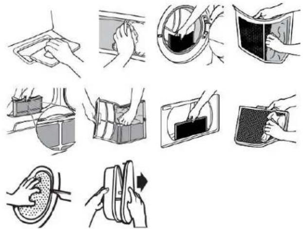
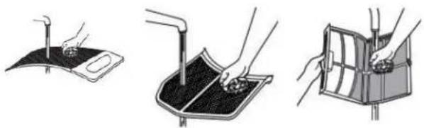
the TO wash:
outRoll lint off the screen with your fingers.
2. Wet both sides of lint screen with hot water.
3. Wet a nylon brush with hot water and liquid detergent. Scrub lint screen with the brush to remove residue buildup.
natural_image
Three-step illustration showing a hand holding a small object, a tool on a surface, and a device with a handle (no text or symbols)
natural_image
Illustration of two hand-drawn photos showing hands cleaning a surface and a meshed plate (no text or symbols)
- Rinse screen with hot water.
- Thoroughly dry lint screen with a clean towel. Reinstall screen in dryer.
Changing the Drum Light (on some models)
■ Use no more than four 90° elbows in a vent system; each bend and curve reduces airflow.
-
Unplug dryer or disconnect power.
-
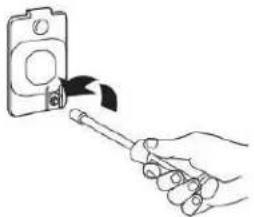
Open the dryer door. Locate the light bulb cover on the back wall of the dryer. Using a 1/4" (6.5 mm) nut driver or socket wrench, remove the screw located in the lower right-hand corner of the cover. Remove the cover.
natural_image
Hand holding a screwdriver to switch a device (no text or symbols visible)
- Turn bulb counterclockwise. Replace the bulb with a 10 W appliance bulb only. Replace the cover and secure with the screw.
- Plug in dryer or reconnect power.
Check Your Vent System for Good Airflow
WARNING

Fire Hazard
Use a heavy metal vent.
Do not use a plastic vent.
Do not use a metal foil vent.
Failure to follow these instructions can result in death or fire.
Good Airflow
Along with heat, dryers require good airflow to efficiently dry laundry. Proper venting will reduce your drying times and improve your energy savings. See Installation Instructions.
The venting system attached to the dryer plays a big role in go airflow. Blocked or crushed vents as well as improper venting installation will reduce air flow and dryer performance.
Service calls caused by improper venting are not covered by the warranty and will be paid by the customer, regardless of who installed the dryer. To clean or repair venting, contact a venting specialist.
Maintain Good Airflow
■ Cleaning your lint screen before each load.
■ Replace plastic or foil vent material with 4" (102 mm) diameter heavy, rigid vent material.
■ Use the shortest length of vent possible.
■ Remove lint and debris from the exhaust hood.
■ Remove lint from the entire length of the vent system at least every 2 years. When cleaning is complete, be sure to follow the Installation Instructions for final product check.
■ Clear away items from the front of the dryer.
Nonuse, Storage, and Moving Care Nonuse or Storage Care
If you will be on vacation or not using your dryer for an extended period of time, you should:
- Unplug dryer or disconnect power.
- Clean lint screen. See "Cleaning the Lint Screen."
- Steam Models Only: Turn off the water supply to the dryer. This helps to avoid flooding (due to a water pressure surge) while you are away.
Moving Care
For power supply cord-connected dryers:
- Unplug the power supply cord.
- Steam models only: Shut off water faucet. Disconnect the water inlet hose from faucet; then drain the hose. Transport hose separately.
- Make sure leveling legs are secure in dryer base.
- Use tape to secure dryer door.
For direct-wired dryers:
WARNING
Electrical Shock Hazard
Disconnect power before servicing.
Replace all parts and panels before operating.
Failure to do so can result in death or electrical shock.
- Turn off power at fuse or breaker box.
- Disconnect wiring.
- Steam models only: Shut off water faucet. Disconnect the water inlet hose from faucet; then drain the hose. Transport hose separately.
- Make sure leveling legs are secure in dryer base.
- Use tape to secure dryer door.
To winterize the dryer:
- Unplug dryer or disconnect power.
- Shut off water faucet.
- Disconnect water inlet hose from faucet and drain.
To use the dryer again:
- Flush water pipes. Reconnect water inlet hose to faucet. Turn on water faucet.
- Plug in dryer or reconnect power as described in the Installation Instructions.
Reinstalling the Dryer
Follow the Installation Instructions to locate, level, and connect the utility knife dryer.
Special Instructions for Steam Models
Install and store your dryer where it will not freeze. Because some water may stay in the hose, freezing can damage your dryer. If storing or moving your dryer during freezing weather, winterize it.
Water inlet hose
Replace inlet hose and hose screen after 5 years of use to reduce the risk of hose failure. Periodically inspect and replace inlet hose if bulges, kinks, cuts, wear, or leaks are found.
When replacing your inlet hose, record the date of replacement.
natural_image
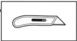
Simple line drawing of a flat tool with a handle and central slot (no text or symbols)
Utility knife
natural_image
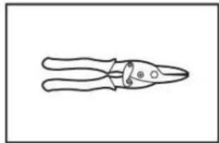
Line drawing of a pair of pliers (no text or symbols)
Tin snips
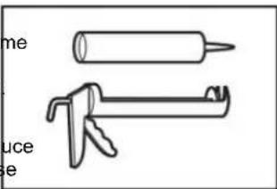
Caulking gun and compound
natural_image
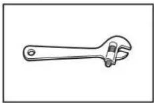
Line drawing of an adjustable wrench (no text or symbols)
Adjustable wrench that opens to 1" (25 mm) or hex-head socket wrench
INSTALLATION REQUIREMENTS
NOTE: Install the clothes dryer according to the manufacturer's instructions and local codes.
Gather required tools and parts before starting installation. Read and follow the instructions provided with any tools listed here.
natural_image
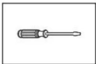
Simple line drawing of a screwdriver (no text or symbols)
Flat-blade screwdriver
natural_image
Line drawing of a pair of wire crimping tools (no text or symbols)
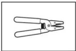
Wire stripper
natural_image
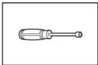
Simple line drawing of a screwdriver with a handle and shaft (no text or symbols)
1/4" Nut driver
natural_image
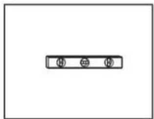
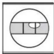
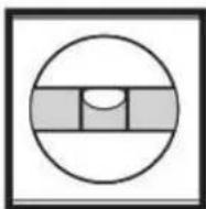
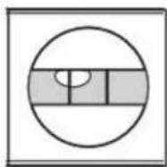
Simple diagram with three circular symbols inside a rectangular box (no text or labels)
Level
natural_image
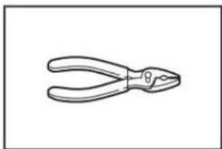
Line drawing of a pair of pliers (no text or symbols)
Pliers
natural_image
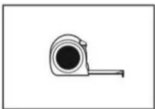
Simple line drawing of a measuring tape (no text or symbols)
Tape measure
natural_image
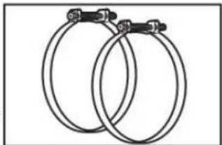
Two interlocked circular hoses with metal clips attached (no text or symbols)
Vent Clamps
Parts Supplied:
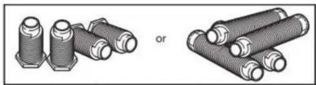
natural_image
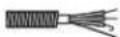
Illustration of two types of threaded fasteners or bushers, one with hexagonal end caps and the other with coiled spring-like structures (no text or symbols)
Leveling legs (4) (Length and appearance of legs may vary according to model)
Parts package is located in dryer drum. Check that all parts are included.
NOTE: Do not use leveling legs supplied with dryer if installing with a pedestal or stack kit.
Parts Needed (steam models):
natural_image
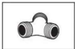
Simple line drawing of a T-shaped pipe fitting with two flanged ends (no text or symbols)
"Y" connector

natural_image
Simple line drawing of a ring-shaped object (no text or symbols)
Rubber washer
natural_image
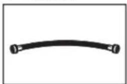
Simple black curved line with endpoints marked by small circles (no text or symbols)
2' (0.6 m) inlet hose
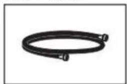
natural_image
Coiled black cable or hose with two connectors at ends (no text or symbols visible)
5' (1.52 m) inlet hose
Parts Needed (not supplied with dryer):
Additional parts may be required, depending on your installation. (7°C). Lower temperatures may cause dryer not to shut off at end Check local codes. Check existing electrical supply and venting of automatic sensor cycles, resulting in longer drying times.
See "Electrical Requirements" and "Venting Requirements" before purchasing parts.
Installation clearances:
For each arrangement, consider allowing more space for ease of mobile home installations require metal exhaust system hardware. Installation and servicing, spacing for companion appliances, and available for purchase from the dealer from whom you purchased clearances for walls, doors, and floor moldings. Space must be your dryer. For further information, please refer to the Quick State. Charge enough to allow the dryer door to fully open. Add spacing on Guide for service contact information. All sides of the dryer to reduce noise transfer. If a closet door is
Available Accessories:
Accessories and replacement parts are available for your model. For ordering and contact information, please reference your Quick Start Guide.
IMPORTANT: Do not operate dryer at temperatures below 45^ F ( 7^ C). Lower temperatures may cause dryer not to shut off at end of automatic sensor cycles, resulting in longer drying times.
Installation clearances:
For each arrangement, consider allowing more space for ease of installation and servicing, spacing for companion appliances, and clearances for walls, doors, and floor moldings. Space must be large enough to allow the dryer door to fully open. Add spacing on all sides of the dryer to reduce noise transfer. If a closet door is used, top and bottom air openings are required. Louvered doors with equivalent ventilation openings can be used.
Location Requirements
WARNING
Explosion Hazard
Keep flammable materials and vapors, such as gasoline, away from dryer.
Do not dry anything that has ever had anything flammable on it (even after washing).
Place dryer at least 18 inches (460 mm) above the floor for a garage installation.
Failure to do so can result in death, explosion, or fire.
Check code requirements. Some codes limit, or do not permit, installing dryer in garages, closets, mobile homes, or sleeping quarters. Contact your local building inspector.
You will need:
■ A location allowing for proper exhaust installation. See "Venting Requirements."
■ A separate 30 A circuit for electric dryers.
If you are using power supply cord, a grounded electrical outlet located within 2 ft (610 mm) of either side of dryer. See "Electrical Requirements."
■ A sturdy floor to support dryer weight of 200 lbs (90.7 kg). Also, consider the combined weight of the companion appliance.
For steam models only: Cold water faucets located within 4 ft (1.2 m) of the water fill valves, and water pressure of 20-120 psi (138-827 kPa). You may use the water supply for your washer using the necessary parts as noted in "Parts needed" which you may need to purchase (those parts are not included with the your appliance and are optional).
■ Level floor with a maximum slope of 1" (25 mm) under the entire dryer. If the slope is greater than 1" (25 mm), install Extended Dryer Feet Kit. If not level, clothes may not tumble properly and automatic sensor cycles may not operate correctly.
For garage installation, place dryer at least 18" (460 mm) above the floor. If using a pedestal, you will need 18" (460 mm) to bottom of the dryer.
■ The dryer must not be installed or stored in an area where it will be exposed to water and/or weather.
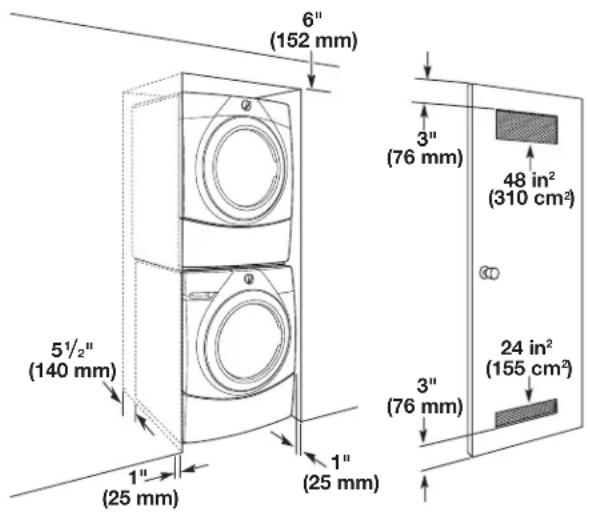
Installation spacing for a recessed area or closet
All dimensions show recommended and minimum spacing allowed.
■ Additional spacing should be considered for ease of installation and servicing.
■ Additional clearances might be required for wall, door, floor, moldings, dryer venting, and drain system.
■ Additional spacing should be considered on all sides of the dryer to reduce noise transfer.
■ For closet installation with a door, minimum ventilation openings in the top and bottom of the door are required for vented models. Louvered doors with equivalent ventilation openings are acceptable.
■ Companion appliance spacing should also be considered.
Recommended installation clearances:
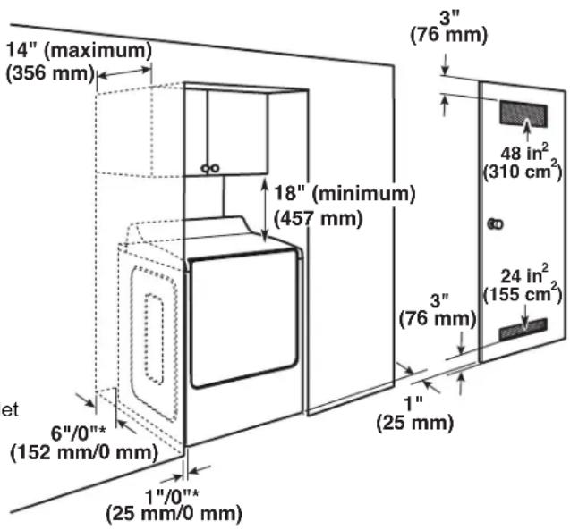
*Recommended/Minimum spacing
Closet Installation (stacked washer and dryer):
Minimum installation clearances (dryer only):
| Front Sides | Rear Top | | |
| Recessed | NA 0" (0 mm) | 0" (0 mm) NA | | |
| Closet | 1" (25 mm) 0" | (0 mm) 0" (0 mm) NA | | |
0" (0 mm) rear spacing is allowed for straight-back venting only. For steam models only, inlet hose must not be kinked.
IMPORTANT: Keep a minimum of 5 12 " (139.7 mm) clearance between the wall and the dryer to avoid crushing the vent.
Mobile Home – Additional installation requirements
This dryer is suitable for mobile home installations. The installation must conform to the Manufactured Home Construction and Safety Standard, Title 24 CFR, Part 3280 (formerly the Federal Standard for Mobile Home Construction and Safety, Title 24, HUD Part 280) or the Standard for Mobile Homes, CAN/CSA-Z240 MH.
Mobile home installations require:
■ Metal exhaust system hardware, which is available for purchase from your dealer.
■ Special provisions must be made in mobile homes to introduce outside air into the dryer. The opening (such as a nearby window) should be at least twice as large as the dryer exhaust opening.
Electrical Requirements - U.S.A.
WARNING
Electrical Shock Hazard
Plug into a grounded 3 or 4 prong outlet.
Do not remove ground prong.
Do not use an adapter.
Do not use an extension cord.
Failure to follow these instructions can result in death, fire, or electrical shock.
It is your responsibility:
■ To contact a qualified electrical installer.
To be sure that the electrical connection is adequate and in conformance with the National Electrical Code, ANSI/NFPA 70 – latest edition and all local codes and ordinances. The National Electrical Code requires a 4-wire power supply connection for homes built after 1996, dryer circuits involved in remodeling after 1996, and all mobile home installations. A copy of the above code standards can be obtained from: National Fire Protection Association, One Batterymarch Park, Quincy, MA 02169–7471.
■ To supply the required 3- or 4-wire, single-phase, 120/240 V, 60 Hz AC only electrical supply (or 3- or 4-wire, 120/208 V electrical supply, if specified on the serial/rating plate) on a separate 30 A circuit, fused on both sides of the line. Connect to an individual branch circuit. Do not have a fuse in the neutral or grounding circuit.
■ Do not use an extension cord.
If codes permit and a separate ground wire is used, it is recommended that a qualified electrician determine that the ground path is adequate.
Electrical Connection
To properly install your dryer, you must determine the type of electrical connection you will be using and follow the instructions provided for it here.
This dryer is manufactured ready to install with a 3-wire electrical supply connection. The neutral bond conductor is permanently connected to the neutral conductor (white wire) within the dryer. If the local electrical codes require the use of a ground-fault circuit interrupter, then a 4 wire electrical supply connection is required. The neutral bond conductor must be removed from the external ground connector (green screw), and secured under the neutral terminal (center or white wire) of the terminal block. When the neutral bond conductor is secured under the neutral terminal (center or white wire) of the terminal block, the dryer cabinet is isolated from the neutral conductor. The green ground wire of the 4-wire power cord must be secured to the dryer cabinet with the green ground screw.
If local codes do not permit the connection of a neutral bond wire to the neutral wire, see "Optional 3-Wire Connection."
A 4-wire power supply connection must be used when the appliance is installed in a location where grounding through the neutral conductor is prohibited. Grounding through the neutral conductor is prohibited for (1) new branch-circuit installations after 1996, (2) mobile homes, (3) recreational vehicles, and (4) areas where local codes prohibit grounding through the neutral conductors.
If using a power supply cord:
Use a UL listed power supply cord kit marked for use with clothes dryers. The kit should contain:
■ A UL listed 30 A power supply cord, rated 120/240 V minimum. The cord should be type SRD or SRDT and be at least 4 ft (1.22 m) long. The wires that connect to the dryer must end in ring terminals or spade terminals with upturned ends.
■ A UL listed strain relief.
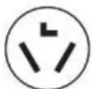
If your outlet looks like this:

4-wire receptacle (14-30R)
Then choose a 4-wire power supply cord with ring or spade terminals and UL listed strain relief. The 4-wire power supply cord, at least 4 ft (1.22 m) long, must have four 10-gauge copper wires and match a 4-wire receptacle of NEMA Type 14-30 R. The ground wire (ground conductor) may be either green or bare. The neutral conductor must be identified by a white cover.
If your outlet looks like this:
3-wire receptacle (10-30R)
Then choose a 3-wire power supply cord with ring or spade terminals and UL listed strain relief. The 3-wire power supply cord, at least 4 ft (1.22 m) long, must have three 10-gauge copper wires and match a 3-wire receptacle of NEMA Type 10-30R.
If connecting by direct wire:
Power supply cable must match power supply (4-wire or 3-wire) and be:
■ Flexible armored cable or nonmetallic sheathed copper cable (with ground wire), covered with flexible metallic conduit. All current-carrying wires must be insulated.
■ 10-gauge solid copper wire (do not use aluminum) at least 5 ft (1.52 m) long.
GROUNDING INSTRUCTIONS
For a grounded, cord-connected appliance:
This appliance must be grounded. In the event of a malfunction or breakdown, grounding will reduce the risk of electric shock by providing a path of least resistance for electric current. This appliance is equipped with a cord having an equipment-grounding conductor and a grounding plug. The plug must be plugged into an appropriate outlet that is properly installed and grounded in accordance with all local codes and ordinances.
WARNING: Improper connection of the equipment-grounding conductor can result in a risk of electric shock. Check with a qualified electrician or serviceman if you are in doubt as to whether the appliance is properly grounded. Do not modify the plug provided with the appliance: If it will not fit the outlet, have a proper outlet installed by a qualified electrician.
For a permanently connected appliance:
This appliance must be connected to a grounded metal, permanent wiring system, or an equipment-grounding conductor must be run with the circuit conductors and connected to the equipment-grounding terminal or lead on the appliance.
SAVE THESE INSTRUCTIONS
Electric Requirements – Canada
WARNING
Electrical Shock Hazard
Plug into a grounded 4 prong outlet.
Failure to do so can result in death or electrical shock.
It is your responsibility:
■ To contact a qualified electrical installer.
To be sure that the electrical connection is adequate and in conformance with Canadian Electrical Code, C22.1 – latest edition and all local codes. A copy of above codes standard may be obtained from: Canadian Standards Association, 178 Rexdale Blvd., Toronto, ON M9W 1R3 CANADA.
■ To supply the required 4-wire, single-phase, 120/240 V, 60 Hz AC only electrical supply on a separate 30 A circuit, fused on both sides of the line. A time-delay fuse or circuit breaker is recommended. Connect to an individual branch circuit.
This dryer is equipped with a UL-listed and/or CSA International Certified Power Cord intended to be plugged into a standard 14-30R wall receptacle. The cord is 5 ft (1.52 m) long. Be sure wall receptacle is within reach of dryer's final location.

4-wire receptacle (14-30R)
■ If codes permit and a separate ground wire is used, it is recommended that a qualified electrician determine that the ground path is adequate.
■ Do not use an extension cord.
For further information, or to obtain a Power Supply Cord Replacement, please reference the contact information listed on your Quick Start Guide.
GROUNDING INSTRUCTIONS
For a grounded, cord-connected appliance:
This appliance must be grounded. In the event of a malfunction or breakdown, grounding will reduce the risk of electric shock by providing a path of least resistance for electric current. This appliance is equipped with a cord having an equipment-grounding conductor and a grounding plug. The plug must be plugged into an appropriate outlet that is properly installed and grounded in accordance with all local codes and ordinances.
WARNING: Improper connection of the equipment-grounding conductor can result in a risk of electric shock. Check with a qualified electrician or serviceman if you are in doubt as to whether the appliance is properly grounded. Do not modify the plug provided with the appliance: if it will not the outlet, have a proper outlet installed by a qualified electrician.
SAVE THESE INSTRUCTIONS
INSTALLATION
Install Leveling Legs
WARNING
Excessive Weight Hazard
Use two or more people to move and install or uninstall appliance.
Failure to do so can result in back or other injury.
1. Prepare dryer for leveling legs
natural_image
Technical line drawing of a mechanical housing with mounting holes and internal components (no text or symbols)
2. Screw in leveling legs
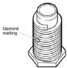
Leveling leg with diamond marking.
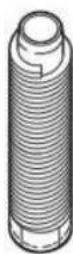
Leveling leg without diamond marking
Using a wrench and tape measure, screw leveling legs into leg holes until bottom of foot is approximately 1/2" (13 mm) to 1 ^1/2 " (38 mm) from bottom of the dryer.
For leveling legs with the diamond marking:
Screw legs into leg holes by hand. Use a wrench to finish turning legs until diamond marking is no longer visible.
Place a carton corner post from dryer packaging under each of the two dryer back corners. Stand the dryer up. Slide the dryer on the corner posts until it is close to its final location. Leave enough room to connect the exhaust vent.
Electrical Installation - U.S.A.
WARNING
Fire Hazard
For power supply cord, use a new UL listed 30 A power supply cord.
For direct wire, use 10 gauge copper wire.
Use a UL listed strain relief.
Disconnect power before making electrical connections.
Connect neutral wire (white or center wire) to center terminal (silver).
Connect ground wire (green or bare wire) to green ground connector.
Connect remaining 2 supply wires to remaining 2 terminals (gold).
Securely tighten all electrical connections.
Failure to do so can result in death, fire, or electric shock.
To avoid damaging floor, use a large flat piece of cardboard from dryer carton; place under entire back edge of dryer. Firmly grasp dryer body (not console panel) and gently lay dryer down on cardboard.
NOTE: Residual water from factory testing may drain when dryer is laying on its side.
Disconnect power
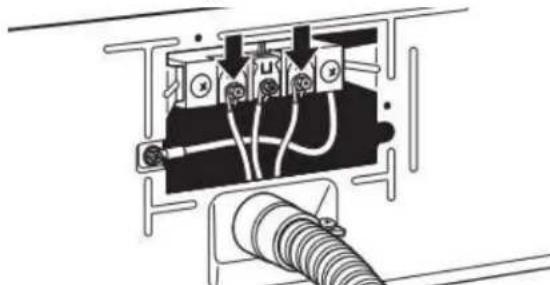
2. Remove terminal block cover
NOTE: Your terminal block cover may be in a different location.
natural_image
Line drawing of a microwave oven with ventilation slots and control panel (no text or symbols)
Remove hold-down screw and terminal block cover.
3. Choose electrical connection type

Power supply cord 4-wire receptacle (NEMA Type 14-30R): Refer to "4-Wire Power Supply Connection". Then, go to "Venting Requirements."

Power supply cord 3-wire receptacle (NEMA Type 10-30R): Refer to "3-Wire Power Supply Connection". Then, go to "Venting Requirements."
4-wire direct connection: Go to "Direct Wire Strain Relief," then "4-Wire Direct Wire Connection," then, go to "Venting Requirements."
3-wire direct connection: Go to "Direct Wire Strain Relief", then "3-Wire Direct Wire Connection," then, go to "Venting Requirements."
NOTE: If local codes do not permit connection of a cabinet-ground conductor to neutral wire, go to "Optional 3-wire Connection." This connection may be used with either a power supply cord or a direct wire connection.
Power Supply Cord Connection
Power Supply Cord Strain Relief
1. Attach power supply cord strain relief
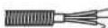
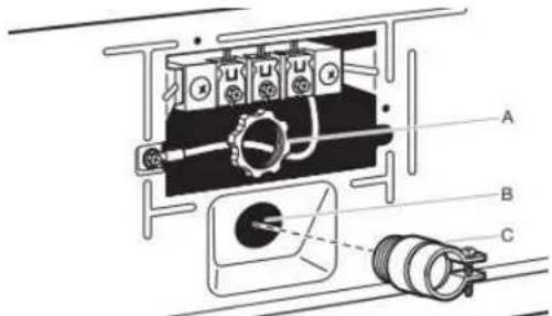
Remove the screws from a 3/4" (19 mm) UL-listed strain relief (UL marking on strain relief). Put the tabs of the two clamp sections (C) into the hole below the terminal block opening (B) so that one tab is pointing up (A) and the other is pointing down (D), and hold in place. Tighten strain relief screws just enough to hold the two clamp sections (C) together.
2. Attach power supply cord to strain relief
natural_image
Pure electrical circuit lines without any symbols
Put power supply cord through the strain relief. Be sure that the wire insulation on the power supply cord is inside the strain relief. The strain relief should have a tight fit with the dryer cabinet and be in a horizontal position. Tighten the strain relief against the power supply cord. Do not overtighten the strain relief screws.
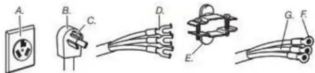
4-Wire Power Supply Connection
IMPORTANT: A 4-wire connection is required for mobile homes and where local codes do not permit the use of 3-wire connections.
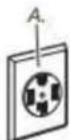
A. 4-wire receptacle (NEMA type 14-30R)
B. 4-prong plug
C. Ground prong
D. Neutral prong
E. Spade terminals with upturned ends
F. 3/4" (19 mm) UL-listed strain relief
G. Ring terminals
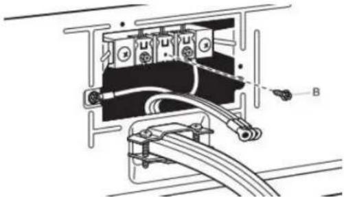
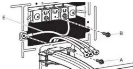
3. Prepare ground wire appliance installation
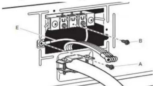
Remove center terminal block screw (B). Remove neutral bond wire (E) from green external ground conductor screw (A).
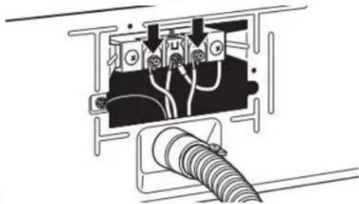
4. Connect neutral bond wire and neutral wire
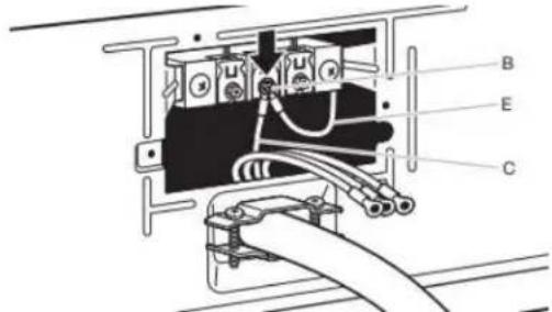
Connect neutral bond wire (E) and neutral wire (white or center) (C) of power supply cord under center terminal block screw (B). Tighten screw.
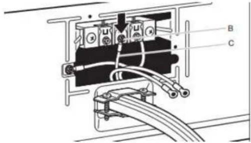
5. Connect ground wire
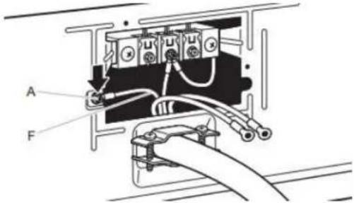
Connect ground wire (F) (green or bare) of power supply cord under green external ground conductor screw (A). Tighten screw.
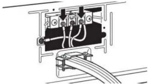
6. Connect remaining wires
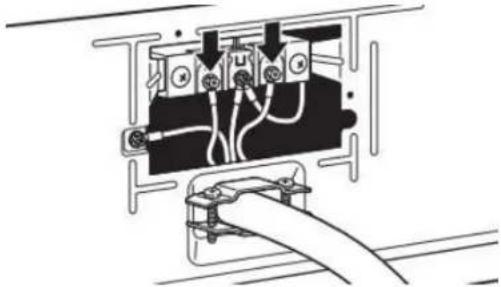
natural_image
Pure electrical circuit lines without any symbols
Connect remaining wires under outer terminal block screws. Tighten screws. Insert tab of terminal block cover into slot of dryer rear panel. Secure cover with hold-down screw. Now, go to "Venting Requirements."
3-Wire Power Supply Connection
IMPORTANT: Use where local codes permit connecting cabinet-ground conductor to neutral wire.
A. 3-wire receptacle (NEMA type 10-30R)
B. 3-wire plug
C. Neutral prong
D. Spade terminals with upturned ends
E. 3/4" (19 mm) UL-listed strain relief
F. Ring terminals
G. Neutral (white or center wire)
3. Remove center screw
natural_image
Technical diagram of an electrical component with labeled parts (no readable text or symbols)
Remove center terminal block screw (B).
4. Connect neutral wire
Connect neutral wire (white or center) (C) of power supply cord under center terminal block screw (B). Tighten screw.
5. Connect remaining wires
natural_image
Pure electrical circuit lines without any symbols
Connect remaining wires under outer terminal block screws. Tighten screws. Insert tab of terminal block cover into slot of dryer rear panel. Secure cover with hold-down screw. Now, go to "Venting Requirements."
Direct Wire Connection
Direct wire strain relief
1. Attach direct wire strain relief
Unscrew the removable conduit connector (A) and any screws from a 3/4" (19 mm) UL-listed strain relief (UL marking on strain relief). Put the threaded section of the strain relief through the hole below the terminal block opening (B). Reaching inside the terminal block opening, screw the removable conduit connector (A) onto the strain relief threads (C) and tighten securely.
2. Attach direct wire cable to strain relief
natural_image
Pure electrical circuit lines without any symbols
Put direct wire cable through the strain relief. The strain relief should have a tight fit with the dryer cabinet and be in a horizontal position. Tighten strain relief screw against the direct wire cable.
For 4-wire Direct Wire Connection, continue to step 3.
4-wire direct wire connection: Go to "4-Wire Direct Wire Connection."
For 3-wire Direct Wire Connection, continue to step 3.
3-wire direct wire connection: Go to "3-Wire Direct Wire Connection."
4-Wire Direct Wire Connection
IMPORTANT: A 4-wire connection is required for mobile homes and where local codes do not permit 3-wire connections.
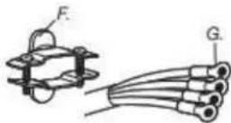
3. Prepare your 4-wire cable for direct connection
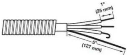
Direct wire cable must have 5 ft (1.52 m) of extra length so dryer may be moved if needed.
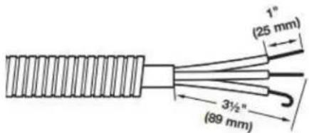
Strip 5" (127 mm) of outer covering from end of cable, leaving bare ground wire at 5" (127 mm). Q2ft (88 mm) from remaining 3 wires. Strip insulation back 1" (25 mm). Shape ends of wires into hooks.
4. Prepare to connect neutral bond wire and neutral wire
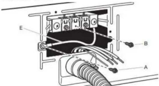
Remove center terminal block screw (B). Remove neutral bond wire (E) from green external bond conductor screw (A).
5. Connect neutral bond wire and neutral wire
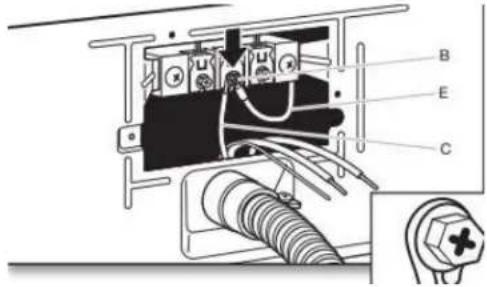
Connect neutral bond wire (E) and place hooked end (hook facing right) of neutral wire (white or center wire) (C) of direct wire cable under center screw of terminal block (B). Squeeze hooked ends together and tighten screw.
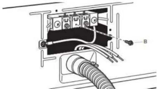
6. Connect ground wire
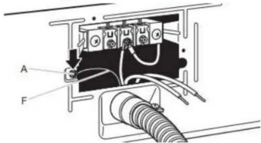
Connect ground wire (green or bare) (F) of direct wire cable under green external ground conductor screw (A). Tighten screw.
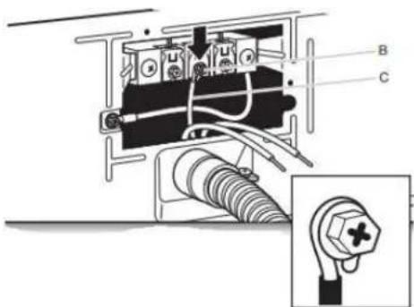
7. Connect remaining wires
natural_image
Pure electrical circuit lines without any symbols
Place hooked ends of remaining direct wire cable wires under outer terminal block screws (hooks facing right). Squeeze hooked ends together and tighten screws. Insert tab of terminal block cover into slot of dryer rear panel. Secure cover with hold-down screw. Now, go to "Venting Requirements."
3-Wire Direct Wire Connection
IMPORTANT: Use where local codes permit connecting cabinet-ground conductor to neutral wire.
3. Prepare your 3-wire cable for direct connection
Direct wire cable must have 5 ft (1.52 m) of extra length so dryer may be moved if needed.
Strip 3/2" (89 mm) of outer covering from end of cable. Strip insulation back 1" (25 mm). If using 3-wire cable with ground wire, cut bare wire even with outer covering. Shape wire end into hooks.
4. Remove center screw
natural_image
Pure electrical circuit lines without any symbols
Remove center terminal block screw (B).
5. Connect neutral wire
Place hooked end of neutral wire (white or center) (C) of direct wire cable under center terminal block screw (B). Squeeze hooked end together. Tighten screw.
6. Connect remaining wires
natural_image
Pure electrical circuit lines without any symbols
Place hooked ends of remaining direct wire cable wires under outer terminal block screws (hooks facing right). Squeeze hooked ends together and tighten screws. Insert tab of terminal block cover into slot of dryer rear panel. Secure cover with hold-down screw. Now, go to "Venting Requirements."
Optional 3-Wire Connection (Power Supply Cord Shown)
IMPORTANT: You must verify with a qualified electrician that this grounding method is acceptable before connecting.
1. Prepare to connect neutral bond wire and neutral wire
Install the correct strain relief for your electrical connection method. Remove center terminal block screw (B). Remove neutral bond wire (E) from green external ground conductor screw (A).
2. Connect neutral bond wire and neutral wire

Connect neutral bond wire (E) and neutral wire (white or center wire) (C) of power supply cord or cable under center terminal block screw (B). Tighten screw.
3. Connect remaining wires
Place remaining wires under outer terminal block screws. Tighten screws.
4. Connect external ground wire
Connect a separate copper ground wire (G) from the green external ground conductor screw (A) to an adequate ground. Insert tab of terminal block cover into slot of dryer rear pan Secure cover with hold-down screw. Now, go to "Venting Requirements."
Venting Requirements
■ Only a 4" (102 mm) heavy metal exhaust vent and clamps may be used.
■ Do not use plastic or metal foil vent.
■ Recommended for best drying performance and to avoid crushing and kinking.
■ Must be fully extended and supported in final dryer location.
■ Remove excess to avoid sagging and kinking that may result in reduced airflow and poor performance.
■ Do not install in enclosed walls, ceilings, or floors.
■ The total length should not exceed 14 ft (2.4 m).
■ The length of flexible metal vent used must be included in the overall vent system design as shown in the "Vent System Chart."
Home Venting System:
■ If using an existing home vent system, clean lint from the entire length of the system before installing the dryer.
■ Make sure external exhaust hoods outside of the home is not plugged with lint or other outside debris.
- Replace plastic or metal foil vents with rigid metal or flexible metal vents. Review "Vent System Chart" and, if necessary, modify existing home vent system to achieve best drying performance.
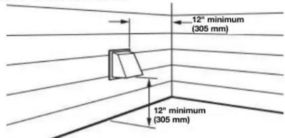
Exhaust hoods:
■ An exhaust hood should cap the vent to keep rodents and insects from entering the home.
■Must be at least 12" (305 mm) from ground or any object that may obstruct exhaust (such as flowers, rocks, bushes, or snow).
■ Do not use an exhaust hood with a magnetic latch.
Recommended Styles: Acceptable Style:
Louvered Hood Box Hood Angled Hood
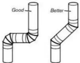
Elbows:
■ 45° elbows provide better airflow than 90° elbows.
Fire Hazard
Use a heavy metal vent.
Do not use a plastic vent.
Do not use a metal foil vent.
Failure to follow these instructions can result in death or fire.
WARNING: To reduce the risk of fire, this dryer MUST BE EXHAUSTED OUTDOORS.
IMPORTANT: Observe all governing codes and ordinances. Dryer exhaust must not be connected into any gas vent, chimney, wall, ceiling, attic, crawlspace, or a concealed space of a building. Only rigid or flexible metal vent shall be used for exhausting. Do not use plastic or metal foil vent.
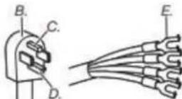
Clamps:
■ Use clamps to seal all joints.
Exhaust vent must not be connected or secured with screws or other fastening devices that extend into interior of duct and only catch lint. Do not use duct tape.
Vent products can be purchased from your dealer. For contact and ordering information, refer to your Quick Start Guide.
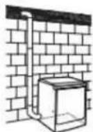
Plan Vent System
Recommended exhaust installations:
Typical installations vent the dryer from the rear of the dryer. installations are possible.
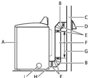
A. Dryer
B. Elbow
C. Wall
D. Exhaust hood
E. Clamps
F. Rigid metal or flexible metal vent
G. Vent length necessary to connect elbows
H. Exhaust outlet
1. Optional side exhaust outlet
Optional exhaust installations:
WARNING

Fire Hazard
Cover unused exhaust holes with a manufacturer's exhaust cover kit.
Contact your local dealer.
Failure to follow these instructions can result in death, fire, electrical shock, or serious injury.
Some models can be converted to exhaust out the right side, left side, or through the bottom. If you prefer, you may contact your local dealer to have the dryer converted.
A
B
C
A. Standard rear offset exhaust installation
B. Left or right side exhaust installation (available only on select 27" wide models).
C. Bottom exhaust installation (available only on select 27 wide models).
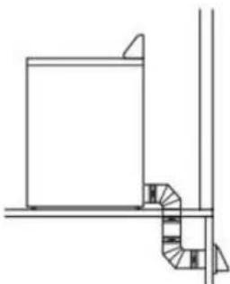
Alternate installations for close clearances
Venting systems come in many varieties. Select the type best for your installation. Two close-clearance installations are shown.
NOTE: The following kits for close-clearance alternate installations are available for purchase. Refer to Quick Start Guide for contact information.
natural_image
Line drawing of a portable electronic device with a coiled cable or hose, showing internal components and a magnified inset (no text or symbols)
Over-The-Top installation (also available with one offset elbow)
natural_image
Line drawing of a mechanical device with internal components and a handle (no text or symbols)
Periscope installation
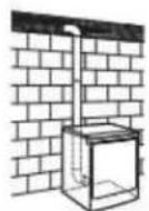
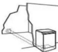
Special provisions for mobile home installations:
Exhaust vent must be securely fastened to a noncombustible portion of the mobile home and must not terminate beneath the mobile home. Terminate exhaust vent outside.
natural_image
Pure architectural line drawing of a staircase and window frame structure without any text or symbols
Determine vent path:
■ Select route that will provide straightest and most direct path outdoors.
■ Plan installation to use fewest number of elbows and turns.
■ When using elbows or making turns, allow as much room as possible.
■ Bend vent gradually to avoid kinking.
■ Use as few 90° turns as possible.
■ Use following "Vent System Chart" to determine type of vent material and hood combinations acceptable to use.
NOTE: Do not use vent runs longer than those specified in "Vent System Chart." Exhaust systems longer than those specified will:
■ Shorten life of dryer.
■ Reduce performance, resulting in longer drying times and increased energy usage.
The "Vent System Chart" provides venting requirements that will help achieve best drying performance.
| Vent System Chart |
| Number of 90° turns or elbows | Type of vent | Box/louvered or Angled hoods |
| 0 | Rigid metal 64 ft (20 m) |
| 1 | Rigid metal 54 ft (16.5 m) |
| 2 | Rigid metal 44 ft (13.4 m) |
| 3 | Rigid metal 35 ft (10.7 m) |
| 4 | Rigid metal 27 ft (8.2 m) |
NOTE: Side and bottom exhaust installations have a 90° turn inside the dryer. To determine maximum exhaust length, add one 90° turn to the chart.
Additional Elbows
In cases in which the Installation Instructions do not address vent length for the specific number of elbows required for a particular application, the following calculations may be used. (The total vent system length includes all straight and curved portions of the vent system):
For 90° elbows, reduce the allowable vent system length by 10 ft (3.05 m).
For 45° elbows, reduce the allowable vent system length by 6 ft (1.83 m).
For example, if the Installation Instructions state that a dryer is allowed 40 ft (12.2 m) of total vent length with two 90° bends, the total allowable vent length would be reduced by 20 ft (6.0 m) (from 40 ft [12.2 m] to 20 ft [6.0m]).
Install Vent System
1. Install exhaust hood
Install exhaust hood and use caulking compound to seal exterior wall opening around exhaust hood.
2. Connect vent to exhaust hood

natural_image
Pure technical line drawing of a curved pipe or duct with a vertical support (no text or symbols)
Vent must fit over the exhaust hood. Secure vent to exhaust hood with 4" (102 mm) clamp. Run vent to dryer location using straightest path possible. Avoid 90° turns. Use clamps to seal all joints. Do not use duct tape, screws, or other fastening devices that extend into interior of vent to secure vent, because they can catch lint.
Connect Inlet Hoses
For vented, non-steam models, skip to "Connect Vent." The dryer must be connected to the cold water faucet using the new inlet hoses. Do not use old hoses.
NOTE: Replace inlet hoses after 5 years of use to reduce the risk of hose failure. Record hose installation or replacement dates on the hoses for future reference.
Periodically inspect and replace hoses if bulges, kinks, cuts, wear, or leaks are found.
1. Turn cold water off, remove and replace rubber washer
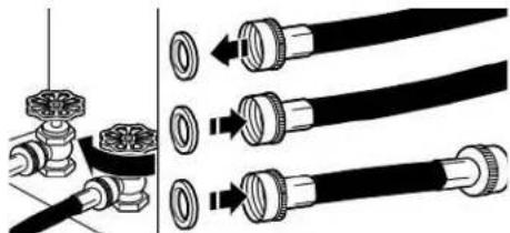
natural_image
Diagram showing pipe fittings and valve connections (no text or symbols)
Turn cold water faucet off and remove washer inlet hose. Remove old rubber washer from inlet hose and replace with new rubber washer.
2. Attach short hose and "Y" connector
natural_image
Diagram of a pipe connection with valves and fittings (no text or labels)
Attach 2 ft (0.6 m) inlet hose to cold water faucet. Screw on coupling by hand until it is seated on faucet. Then attach "Y" connector to male end of the 2 ft (0.6 m) inlet hose. Screw on coupling by hand until it is seated on connector.
3. Tighten couplings
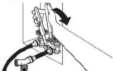
natural_image
Diagram of a hand using a valve to interact with a mechanical component (no text or symbols visible)
Using pliers, tighten the couplings with additional two-thirds turn.
NOTE: Do not overtighten. Damage to the coupling can result.
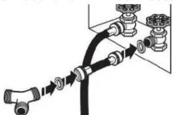
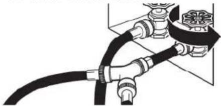
Attach long hose to "Y" connector and tighten couplings
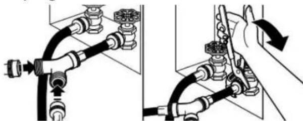
natural_image
Diagram showing two hands operating a pipe fitting with valve fittings (no text or symbols present)
Attach one of the 5 ft (1.5 m) inlet hose ends to the "Y" connector. Attach washer cold inlet hose to other side of "Y" connector. Screw on coupling by hand until it is seated on connector. Using pliers, tighten the couplings an additional two-thirds turn.
NOTE: Do not overtighten. Damage to the coupling can result.
- Attach long hose to dryer fill valve and tighter2. Move dryer to final location coupling
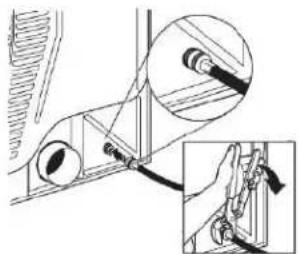
natural_image
Mechanical assembly diagram showing a linkage mechanism with an inset close-up of the detail (no text or symbols)
If applicable, remove protective cap from water inlet valve. Attach other end of long hose to fill valve on dryer back Screw on coupling by hand until it is seated on fill valve connector. Using pliers, tighten the couplings an additional two-thirds turn.
NOTE: Do not overtighten. Damage to the coupling can result.
NOTE: The Steam Dryer water connection may be in a different location.
- Turn on cold water faucet
natural_image
Pure diagram of a pipe fitting with no text, numbers, or symbols
Check that the water faucet is turned on.
- Check for leaks
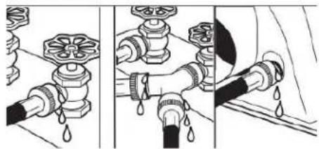
natural_image
Three-panel illustration showing pipe fittings and water droplets during a procedure (no text or symbols)
Check for leaks around "Y" connector, faucets, and hoses.
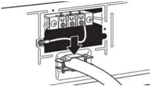
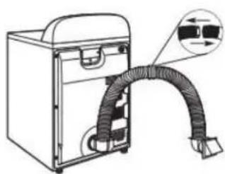
Connect Vent
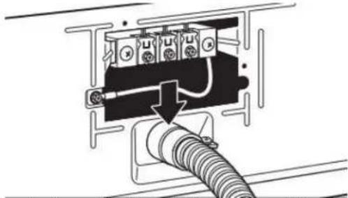
- Connect vent to exhaust outlet
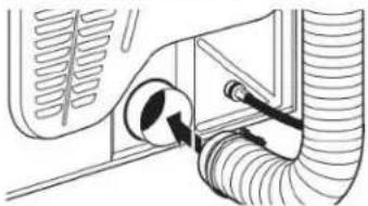
natural_image
Diagram of a vehicle's exhaust pipe system with valve and hose (no text or labels)
Using a 4" (102 mm) clamp, connect vent to exhaust outlet in dryer. If connecting to existing vent, make sure vent is clean. Dryer vent must fit over dryer exhaust outlet and inside exhaust hood. Check that vent is secured to exhaust hood with a 4" (102 mm) clamp.
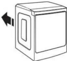
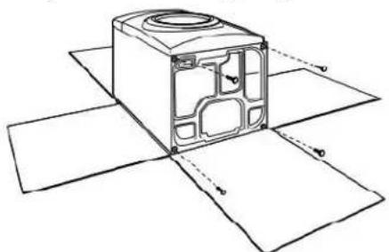
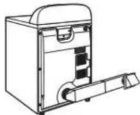
natural_image
Simple line drawing of a box with a door and arrow indicating left motion (no text or symbols)
Move dryer to final location. Avoid crushing or kinking the vent. After dryer is in place, remove corner posts and panel cardboard from under dryer.
IMPORTANT: Keep a minimum of 5 ^1/2 " (139.7 mm) clearance between the wall and the dryer to avoid crushing the vent.
Level Dryer
- Level Dryer
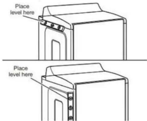
Check levelness of dryer from side to side. Repeat from front to back.
NOTE: The dryer must be level for the moisture-sensing system to operate correctly.
Not Level
LEVEL
Not Level
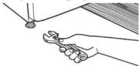
- Tighten and adjust leveling legs
natural_image
Line drawing of a hand using a wrench to lift a pipe (no text or symbols)
If dryer is not level, prop up using a wood block. Use wrench to adjust legs up or down, and check again for levelness.
Once dryer is level, make sure all four legs are snug against the floor and the dryer does not rock.
Complete Installation Checklist
- Check that all parts are now installed. If there is an extra part, go back through steps to see what was skipped.
■ Check that you have all of your tools.
■ Dispose of/recycle all packaging materials.
■ Be sure the water faucets are on.
- Check for leaks around "Y" connector, faucet, and hoses.
- Check dryer's final location. Be sure vent is not crushed or kinked.
- Check that dryer is level. See "Level Dryer."
■ Remove film on console and any tape remaining on dryer.
■ Wipe dryer drum interior thoroughly with a damp cloth to remove any dust.
WARNING
Electrical Shock Hazard
Plug into a grounded 3 or 4 prong outlet.
Do not remove ground prong.
Do not use an adapter.
Do not use an extension cord.
Failure to follow these instructions can result in death, fire, or electrical shock.
■ To change the door swing from a right-side opening to a left-side opening, see online "Dryer Door Reversal Instructions" for details.
■ Set the heat cycle for 20 minutes, and start dryer. Do not select Air Only temperature setting.
If the dryer will not start, check the following:
■ Controls are set in a running or "On" position.
■ Start button has been pushed firmly.
■ Dryer is plugged into an outlet and/or electrical supply.
■ Household fuse is intact and tight, or circuit breaker has not tripped.
■ Dryer door is closed.
■ When the dryer has been running for 5 minutes, open the dryer door and feel for heat. If you feel heat, cancel cycle and close the door.
If you do not feel heat, turn off dryer, and check the following:
■ There may be 2 household fuses or circuit breakers for the dryer. Check that both fuses are intact and tight, or that both circuit breakers have not tripped. If there is still no heat, contact a qualified technician.
NOTE: You may notice an odor when dryer is first heated. This odor is common when heating element is first used. The odor will go away.
If your Airflow screen reads "Check Vent," your dryer vent may be crushed or blocked.
■ For power supply cord installation, plug into a grounded outlet. For direct wire installation, turn on power.
If you live in a hard water area, use of a water softener is recommended to control the buildup of scale through the water system in the dryer. Over time, the buildup of lime scale may clog different parts of the water system, which will reduce product performance. Excessive scale buildup may lead to the need for certain part replacement or repair.
QUICK START GUIDE
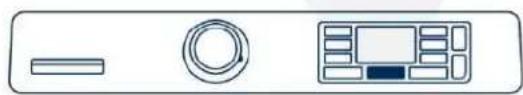
CONTROL PANEL AND FEATURES
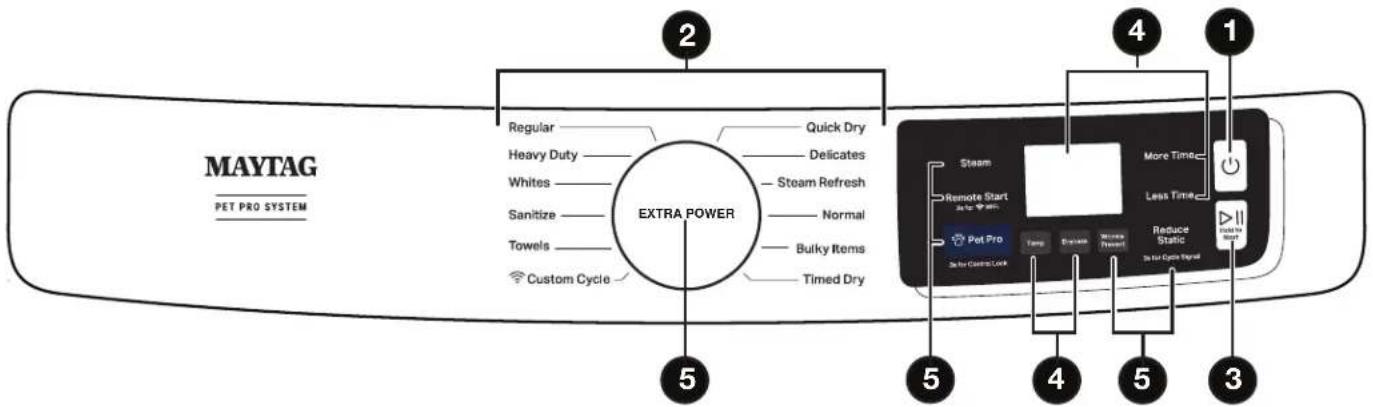
Not all features, cycles, and options are available on all models. Appearance may vary.
NOTE: The control panel features a sensitive surface that responds to a light touch of your finger. To ensure your selections are registered, touch the control panel with your finger tip, not your fingernail. When selecting a setting or option, simply touch its name.
1. POWER/CANCEL
Touch to turn the dryer on/off or to stop/cancel a cycle.
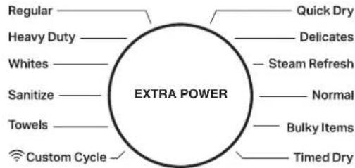
2. CYCLE CONTROL KNOB
Turn the knob to select a cycle for your laundry load. See the "Cycle Guide" section for details.
Activate the Extra Power option for harder-to-dry loads. See the "Options" section for more information.
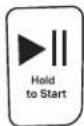
3. START/PAUSE
Touch and hold until LED counts down and the dryer starts; or touch once while a cycle is in process to pause it, touch again to resume.
4. LED DISPLAY AND SETTINGS
Display LCD will show the cycle settings and estimated time remaining. Adding or changing default options will also affect time shown in the display.
See the "Cycle Guide" section for details.
Not all settings are available with all cycles.
More Time/Less Time
Touch to increase or decrease the length of a Timed Dry or Quick Dry cycle.
Temp
When using any cycle except Sanitize, you may select a dry temperature based on the type of load you are drying. Use the warmest setting acceptable for the garments in the load. Follow garment label instructions.
Dryness
When using Sensor Cycles, you may select a Dryness level based on the type of load you are drying (except for the Sanitize cycle).
Cycle Status
The Cycle Status indicators show the progress of a cycle. Touch a button for the desired drying cycle. Not all indicators are available on all models. See the "Cycle Guide" section for cycle details.
Sensing
The Sensing indicator will light during Sensor Cycles to indicate that the moisture sensor on the dryer is operating. This indicator will not light during Timed Cycles or options such as Wrinkle Prevent.
Wet
The load is still wet and/or the cycle just started.
Damp
The load still has moisture remaining, a good point in the cycle to remove a garment to air dry or iron.
Cool Down
The dryer has finished drying with heat and is now tumbling without heat to cool it down and reduce wrinkling.
End
This indicates that the selected cycle has ended and the load may be removed from the dryer. If Wrinkle Prevent has been selected, the dryer may continue to tumble the load, even if "End" is displayed.
Check Vent
The Check Vent indicator is a feature available for Sensor Cycles only. This alert will show the status of airflow through the dryer and the dryer vent system for the dryer's life. During the sensing phase at the beginning of the cycle if it detects a blocked vent or low pressure it will display "Check Vent". Clean lint screen or vent for better performance. This light will stay on for the entire cycle. Refer to the "Troubleshooting" section for potential solutions to the issue. The light will be cleared upon completion of the cycle, touching Power, or opening the door. It will continue to illuminate during the cycle until the vent is cleared.
NOTE: The dryer will continue to operate even while the indicator is lit, but poor airflow can impact dry times and overall performance.
5. OPTIONS
Use to select available options for your dryer. Not all cycles and options are available on all models.
NOTE: For better performance when using Wrinkle Prevent, Reduce Static, Steam and Pet Pro, use with mid to larger load sizes.
Wrinkle Prevent
Touch to turn on/off and on with steam (select models). Wrinkle Prevent adds up to 150 minutes of periodic tumbling and heat to help reduce wrinkling. Wrinkle Prevent with Steam will add a short steam cycle after 60 minutes to help smooth wrinkles.
Reduce Static (on some models)
Touch to add this option to selected Sensor Cycles. The dryer will automatically tumble, pause, and introduce a small amount of moisture into the load to help reduce static. This option adds approximately 3 minutes to the total cycle time.
Steam (steam models only)
Touch to add steam to the end of certain Sensor Cycles to help smooth wrinkles. It is not available on Sanitize, Delicates, Steam Refresh, or Timed Cycles (Timed Dry, Quick Dry). Steam can be used with High or Medium heat settings. This option adds approximately 15 minutes to the total cycle time.
Pet Pro
The Pet Pro option uses a low heat, water and extended dry time to lift pet hair from clothes and capture it in the lint trap.
Remote Start
Touch each time you want to remotely control via the Maytag™app. Follow the instructions in the "GET THE MAYTAG™APP AND GET CONNECTED" section for more details
Note: Once Remote Enable has been selected, certain interactions will cause it to cancel "Remote Enable. Example: Opening the door.
GET THE MAYTAG™ APP AND GET CONNECTED
With your mobile device download the Maytag™ app. You can get subscription and connectivity instructions, terms of use, and privacy policy at www.maytag.com/connect or in Canada www.maytag.ca/connect.
Once installed, launch the app and you will be guided through the steps to subscribe and create your user account to connect to your appliance. If you have any problems or questions, call Maytag® Connected Appliances at 1-866-333-4591. (Only available for models with Wi-Fi capability). When unit is first powered on, it will prompt to select language before you see message to Download APP or press any other key to setup Wi-Fi later.
The Extra Power option can be used with both Sensor and Timed Dry Cycles. Press the knob to activate the Extra Power option, for an additional 10 minutes of cycle time (including additional heat and tumbling, where applicable). When activated, the Cycle Control knob will illuminate and the estimated time remaining on the display will show an additional 10 minutes.
OPERATING INSTRUCTIONS
WARNING
Fire Hazard
No washer can completely remove oil.
Do not dry anything that has ever had any type of oil it (including cooking oils).
Items containing foam, rubber, or plastic must be dried on a clothesline or by using an Air Cycle.
Failure to follow these instructions can result in death fire.
WARNING
Explosion Hazard
Keep flammable materials and vapors, such as gasoline, onaway from dryer.
Do not dry anything that has ever had anything flammable on it (even after washing).
Failure to follow these instructions can result in death, or explosion, or fire.
WARNING: To reduce the risk of fire, electric shock, or injury to persons, read the IMPORTANT SAFETY INSTRUCTIONS, located in your appliance's Owner's Manual, before operating this appliance.
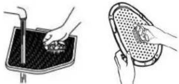
- Clean Lint Screen
natural_image
Illustration showing two steps of cleaning a car wheel rim and its interior panel (no text or symbols)
- Load Clothes
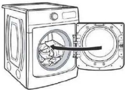
natural_image
Line drawing of a washing machine with an open door showing internal components (no text or symbols)
- Turn Power On

- Close Door; then Select Cycle and Settings
- Press START/PAUSE
| Fire Hazard | Explosion Hazard |
| No washer can completely remove oil. | Keep flammable materials and vapors, such as gasoline, away from dryer. |
| Do not dry anything that has ever had any type of oil on it (including cooking oils). | Do not dry anything that has ever had anything flammable on it (even after washing). |
| Items containing foam, rubber, or plastic must be dried on a clothesline or by using an Air Cycle. | Failure to follow these instructions can result in death, explosion, or fire. |
| Failure to follow these instructions can result in death or fire. | |
WARNING: To reduce the risk of fire, electric shock, or injury to persons, read the IMPORTANT SAFETY INSTRUCTIONS, located in your appliance's Owner's Manual, before operating this appliance.
Sensor Cycles
If settings are changed, the new settings will be remembered. If there is a power failure, settings will return to the default. Not all features and cycles are available on all models. Not all settings and options are available on each cycle.
Use Sensor Cycles for better fabric care and energy savings. The dryer senses moisture in the load or air temperature and shuts off when the load reaches the selected dryness level.
NOTE: All temperatures listed in the first row are available for all cycles unless otherwise stated. Temperatures shown in bold are the default settings for that cycle.
Items to Dry: Cycle: Temperature: Description:
| Heavyweight items such as towels or heavy work clothes | Heavy Duty High Medium Low | Uses stepped drying, starting with High heat, followed by Medium heat for enhanced fabric care and energy savings. |
| Work clothes, casual wear, mixed cottons, sheets, corduroys | Normal Medium Uses Medium heat to dry large loads of mixed fabrics and items.Normal is the most efficient cycle. |
| Undergarments, blouses, lingerie, performance wear | Delicates Low Uses Low heat to gently dry delicate items. |
| Large loads of heavyweight items | Sanitize High | This is a long cycle with High heat, which has been proven to reduce household bacteria. This cycle is not recommended for all fabrics. Use for large loads or heavyweight fabrics. For best results, run cycle to completion. Do not interrupt. |
| Jackets, comforters, pillows, jeans | Bulky Items Medium Use for drying large, bulky items; do not overfill dryer drum.Partway through the cycle, the signal will sound to indicate when it is time to rearrange items for optimal drying. |
| Shirts, blouses, permanent press, synthetics, lightweight items | Regular Medium | Uses Medium heat to dry large loads of mixed fabrics and items. |
| White, sturdy items | Whites High | Uses High heat to dry large loads of white, sturdy fabrics and items. |
| Large loads of towels and heavyweight items | Towels High | This is a long cycle with High heat. This cycle is not recommended for all fabrics. Use for large loads of heavyweight fabrics. |
NOTE: To create a Custom Cycle, download the MayApp and follow the instructions in the app. All cycles that can be saved as a favorite can be customized.
On steam models, you may select the “+Steam” setting to add a short steam cycle after 60 minutes. This is available only with High and Medium drying temperature settings.
Timed Dry Cycles
If settings are changed, the new settings will be remembered (except on Quick Dry). If there is a power failure, settings will return to the default. Not all features and cycles are available on all models. Not all settings and options are available on each cycle.
Adjusting drying time on Timed Cycles
When you select a Timed Dry Cycle, the time appears in the display. Use More Time and Less Time to increase or decrease the time in 5 minute increments. The maximum dry time is 150 minutes.
NOTE: All temperatures listed in the first row are available for all cycles unless otherwise stated. Temperatures shown in bold are the default settings for that cycle.
| Items to Dry: Cycle: | Temperature: | Description: | |
| Any loadNOTE: Select Air Dry to dry foam, rubber, plastic, or heat-sensitive fabrics | Timed Dry High | MediumLowAir Dry | Use to dry items to a damp level for items that do not require entire drying cycle. Select a drying temperature based on the type of fabrics in your load. If you are unsure of the temper to select for a load, select the lower setting rather than the setting. |
| Small loads and sportswear | Quick Dry High | For small loads of 3-4 items. |
On steam models, you may select the “+Steam” setting to add a short steam cycle after 60 minutes. This is available only with High and Medium drying temperature settings.
Steam Cycle (on some models)
Steam cycles are designed for use with dry loads to loosen wrinkles, reduce odors, and refresh fabrics. For better performance, use this cycle when using mid to larger load sizes.
Not all cycles and settings are available on all models. Settings and options shown in bold are default settings for that cycle.
| Items to Refresh: Cycle: Temperature: Description: |
| Shirts, blouses and slacks | Steam Refresh | High Use to smooth | out wrinkles and reduce odors from loads left in the dryer too long. Do not add dryer sheets. |
Selecting the Drying Temperature
| Items to Dry: | Temperature: Description: |
| Towels and work clothes. | High | Heavyweight items |
| Sheets, blouses, dresses, underwear, permanent press fabrics, and some knits. | Low to Medium Medium-weight items |
| Foam, rubber, plastic, other heat-sensitive fabrics. | Air (no heat) | Uses unheated air to dry heat-sensitive items |
| Bonded or laminated fabrics. | N/A | Some items should only be line-dried |
NOTE: If you have questions about drying temperatures for various loads, refer to the care label directions.
Gas Dryer Models
NOTE: These clothes dryer's Government energy certifications were based on the Normal Cycle, Highest Temperature setting and More Dryness Level. The as-shipped defaults of Normal, Medium Temperature and Wrinkle Prevent Off were used except the Temperature Setting was changed from Medium to High and the Dryness level was changed from Normal to More. Cycles that are available for post-sale download may use more energy than the Normal cycle, upon which the energy use rating of this dryer is based upon.
Electric Dryer Models
NOTE: These clothes dryer's Government energy certifications were based on the Normal Cycle, Highest Temperature setting and Normal Dryness Level. The as-shipped defaults of Normal, Medium Temperature and Wrinkle Prevent Off were used except the Temperature Setting was changed from Medium to High. Cycles that are available for post-sale download may use more energy than the Normal cycle, upon which the energy use rating of this dryer is based upon.
TROUBLESHOOTING
| First try the solutions suggested here or visit our website at www.maytag.com/owners (in Canada, www.maytag.ca/owners) for assistance and to possibly avoid a service call. |
| If you experience | Possible Causes Solution | |
| Dryer Operation |
| Dryer will not run Door | or not closed completely. Make sure the | dryer door is closed completely. |
| Start/Pause not touched firmly or held long enough. | Touch and hold START/PAUSE until the display counts down "3-2-1" and the dryer starts. |
| Household fuse is blown or circuit breaker has tripped. | There may be two household fuses or circuit breakers for the dryer. Check that both fuses are intact and tight, or that both circuit breakers have not tripped. Replace the fuses or reset the circuit breaker. If the problem continues, call an electrician. |
| Incorrect power supply. Electric dryers | require 240 V power supply. Check with a qualified electrician. |
| Wrong type of fuse. Use a time-delay fuse. |
| Dryer will not heat | Household fuse is blown or circuit breaker has tripped. | The drum may be turning, but you may not have heat. Electric dryers use two household fuses or circuit breakers. Replace the fuses or reset the circuit breaker. If the problem continues, call an electrician. |
| Incorrect power supply. Electric dryers | require 240 V power supply. Check with a qualified electrician. |
| Supply line valve not open. For gas | dryers, make sure that the valve on the gas supply line is open. |
| Unusual Noise |
| Humming or whining noise with Steam cycle selected (on some models) | Water pump or water inlet valve (depending on model) on dryer is running. | The water pump or water inlet valve on the dryer is used during the Steam function. If the dryer has just been installed or unused for an extended period, the pump or valve may be louder and run longer. This is normal.NOTE: The valve may make this noise even with no water line connected. |
| Thumping noise Dryer | hasn't been used in a while. This is | due to temporary flat spots on the drum rollers. The thumping sound will diminish after a few minutes. |
| Rattling or vibrating noise | A small object caught between the edges of dryer drum. | Check the front and rear edges of the drum for small objects. Clean out pockets before laundering. |
| Dryer isn't properly leveled. The dryer | may vibrate if not properly installed. See the Installation Instructions. All four dryer feet should be in firm contact with the floor. |
| Clothing is balled up in dryer. | When balled up, the load will bounce, causing the dryer to vibrate. Separate the load items and restart the dryer. |
| Clicking noise | Gas valve operating. | On gas dryers, you may hear the gas valve clicking as it opens and closes. This is normal. |
| Loud humming or increased noise during cycle | Load is packed tightly or exhaust vent blocked. | Reduce load size to recommended load size in "Cycle Guide" section. Run the dryer for 5-10 minutes. Hold your hand under the outside exhaust hood to check air movement. If you do not feel air movement or air movement is minimal, clean exhaust system of lint or replace exhaust vent with heavy metal or flexible metal vent. See the Installation Instructions. |
First try the solutions suggested here or visit our website at www.maytag.com/owners (in Canada, www.maytag.ca/owners) for assistance and to possibly avoid a service call.
If you experience Possible Causes Solution
Dryer Results
| Clothes are not drying satisfactorily or drying times are too long | Using Normal cycle. For optimal drying times, use Regular cycle. For optimal energy savings, use Normal cycle. |
| Lint screen is clogged with lint. Clean lint screen before each load. |
| The exhaust vent or outside exhaust hood is clogged with lint, restricting air movement. | Run the dryer for 5–10 minutes. Hold your hand under the outside exhaust hood to check air movement. If you do not feel air movement or air movement is minimal, clean exhaust system of lint or replace exhaust vent with heavy metal or flexible metal vent. See the Installation Instructions. |
| The exhaust vent is not the correct length. | Check that the exhaust vent is not too long or has too many turns. Long venting will increase drying times. See the Installation Instructions. |
| The exhaust vent diameter is not the correct size. | Use 4" (102 mm) diameter vent material. |
| The dryer is not level. Clothes not contacting the moisture sensors during Sensor Cycles. See "Level Dryer" in the Installation Instructions. |
| The AirDry temperature setting has been selected. | Select the correct temperature for the types of garments being dried. See "Cycle Guide" section. |
| The load is too large and heavy to dryseparate the load to tumble freely. quickly. |
| Fabric softener sheets are blocking the The air outlet grille is just inside the door, behind the lint screen. grille. Check that it is not blocked by a fabric softener sheet. Use only one fabric softener sheet, and use it only once. |
| The dryer is located in a room with temperature below 45°F (7°C). | Proper operation of dryer cycles requires temperatures above 45°F (7°C). |
| The dryer is located in a closet. Closet doors must have ventilation openings at the top and bottom of the door. The front of the dryer requires a minimum of 1" (25 mm) of airspace and, for most installations, the rear of the dryer requires 5" (127 mm). See the Installation Instructions. |
| Cycle time is too short | The load may not be contacting the sensor strips on Sensor Cycles. | Level the dryer. See the Installation Instructions. All four dryer feet should be in firm contact with the floor. |
| Steam models only: Clothes are coming out of the Steam Refresh cycle with damp or wet spots. | Under certain environmental installation conditions, you may experience under drying. Select the Timed Dry cycle, medium drying temperature, for 5 to 10 minutes. |
| The Sensor Cycle is ending early. Change the dryness level setting on Sensor Cycles. Increasing or decreasing the dryness level will change the amount of drying time in a cycle. |
Lint on load Lint screen is clogged with lint. Clean lint screen before each load.
Stains on load Improper use of fabric softener. Add dryer fabric softener sheets at the beginning of the cycle. Fabric softener sheets added to a partially dried load can stain your garments. Do not use fabric softener sheets with steam cycles.
Stains on drum Loose dyes in clothes. Drum stains are caused by dyes in clothing (usually blue jeans). These will not transfer to other clothing.
First try the solutions suggested here or visit our website at www.maytag.com/owners (in Canada, www.maytag.ca/owners) for assistance and to possibly avoid a service call.
If you experience Possible Causes Solution
Dryer Results (cont.)
| Loads are wrinkled The load was not removed from dryer at the end of the cycle. | Steam models only: Select Steam Refreshcycle to tumble the load with water and heat. This cycle is best for reducing wrinkles from loads left in the dryer too long.NOTE: Refer to garment care label instructions. Dry-clean-only garments are not recommended. |
| The dryer was tightly packed. Dry smaller loads that can tumble freely. |
| Steam models only: For steam cyclesMake sure water is connected to the dryer. Check that water inlet the water is not properly connected with those is connected to both the faucet and dryer's water inlet valve. The dryer.Check that the water supply is turned on. |
| Odors | Recent painting, staining, or varnishing Ventilate the area. When the odors or fumes are gone from the area, in the area where your dryer is located dewash and dry the clothing. |
| Steam models only: For steam cycles, the water is not properly connected with those is connected to both the faucet and dryer's water inlet valve. The dryer.Check that the water supply is turned on. |
| Odors are left in garments after wearing. | Steam models only: To remove dors left in garments after wearing, select Steam Refresh. The Steam Refresh cycle is best for reducing wrinkles from loads left in the dryer too long. |
| Pet Hair Model with no Pet Pro Feature. N/A |
| Steam models only: Water inlet connected. Make sure water is connected to both the faucet and dryer's water inlet valve. Check that the water supply is turned on. |
| Lint screen is clogged with lint. Clean lint screen before each load. |
| Load too hot Load removed before cool down portion of cycle complete. | Allow the dryer to complete the cool down portion of the cycle before removing the load. |
| Using Timed Dry cycle with a high temperature setting. Select a Sensor cycle with a lower heat setting to avoid over drying the load. |
| Dryer Displaying Code Message or Cycle Status Indicator Lights Up |
| “PF” (power failure) The drying cycle has been interrupted by a power failure. | Touch and hold START/PAUSE to restart the dryer.NOTE: The Control Lock function may be enabled when recovering from a power failure. To unlock the control, touch and hold Control Lock for at least 3 seconds. |
| “L” or “L2” Diagnostic There may be a problem with your Code (low or no line home power supply, keeping the dryer voltage condition) heater from turning on. | The dryer will continue to run when this diagnostic code is present. Touch any setting or option name to clear the code from the display and return to the estimated time remaining.Try the following:Check to see if a household fuse has blown or circuit breaker has tripped. Electric dryers use two household fuses or breakers. Replace the fuse or reset the circuit breaker.Confirm that the power cord is properly installed. Refer to the Installation Instructions for details.Select a Timed Dry heated cycle, and restart the dryer. If the message persists, consult a qualified electrician. |
First try the solutions suggested here or visit our website at www.maytag.com/owners (in Canada, www.maytag.ca/owners) for assistance and to possibly avoid a service call.
If you experience Possible Causes Solution
Dryer Displaying CodeMessage or Cycle Status Indicator Lights Up (cont.)
Check Vent indicator The lint screen or vent is clogged; theThe dryer will continue to run when this diagnostic code is present. is lit. vent is crushed or kinked or has too Touch any setting or option name to clear the code from the display many turns. and return to the estimated time remaining.
Try the following:
■ Clean lint screen.
- Check to see if the vent run from the dryer to the wall is crushed or kinked.
■ Confirm that the vent run from the dryer to the wall is free of lint and debris.
■ Confirm that the exterior vent exhaust hood is free of lint and debris.
■ Confirm that your vent system falls within the recommended run length and number of elbows for the type of vent you are using. Refer to "Plan Vent System" in the Installation Instructions for details.
■ Select a Timed Dry heated cycle, and restart the dryer.
■ If the message persists, have your entire home venting run cleaned.
"F# E#" (F1 E1, F3 The dryer is in need of service. If a code beginning with an "F" appears in the display, alternating E1, etc.) variable between F# and E#, the dryer control has detected a problem that service codes requires service. Call for service.
"Loc" The Control Lock is enabled. Touch and hold Control Lock for 3 seconds to unlock the controls of the dryer. During this time, the LED Display will count down "3-2-1." When the Control Lock is disabled, the LED Display will clear.
SÉCURITÉ DE LA SÉCHEUSE
- Balayer le code QR.
natural_image
Illustration of five different cleaning or cleaning techniques (no text or symbols present)
natural_image
Hand holding a screwdriver to switch a small electronic device (no text or symbols visible)
natural_image
Simple line drawing of a screwdriver (no text or symbols)
natural_image
Line drawing of a pair of wire crimping tools (no text or symbols)
Pince à dénuder
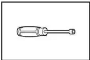
natural_image
Simple line drawing of a screwdriver with a handle and shaft (no text or symbols)
natural_image
Simple diagram with three circular symbols inside a rectangular box (no text or labels)
Niveau
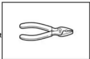
natural_image
Line drawing of a pair of pliers (no text or symbols)
Pince
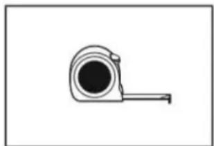
natural_image
Simple line drawing of a measuring tape (no text or symbols)
Ruban à mesurer
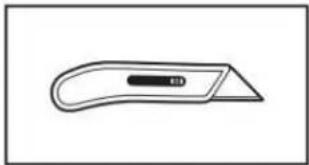
natural_image
Simple line drawing of a flat tool with a handle and central slot (no text or symbols)
Couteau utilitaire
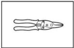
natural_image
Line drawing of a pair of pliers with a handle and base (no text or symbols)
natural_image
Two line drawings of laboratory pipettes: a cylindrical tube and a hand tool (no text or symbols)
natural_image
Line drawing of an adjustable wrench (no text or symbols)
natural_image
Two interlocked metal rings with clamps (no text or symbols)
Brides de conduit
Pièces fournies :
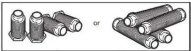
natural_image
Illustration of two types of threaded fasteners, one with hexagonal bolts and the other with coiled tubes (no text or symbols)
natural_image
Simple line drawing of a T-shaped pipe fitting with two side flanges (no text or symbols)
Raccord en « Y »
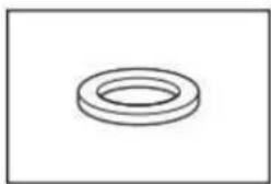
natural_image
Simple line drawing of a ring-shaped object (no text or symbols)
natural_image
Simple black curved line with two endpoints, no text or symbols present
natural_image
Coiled black cable or hose with two connectors at ends (no text or symbols visible)
natural_image
Technical line drawing of a mechanical housing with mounting holes and internal components (no text or symbols)
natural_image
Line drawing of a front-loading washing machine with ventilation slots and control panel (no text or symbols)
natural_image
Pure electrical circuit lines without any symbols
natural_image
Pure electrical circuit lines without any symbols
natural_image
Pure electrical circuit lines without any symbols
natural_image
Technical diagram of an electrical component with labeled parts (no readable text or symbols)
Retirer la vis de la borne centrale (B).
Méthode de raccordement direct
natural_image
Diagram of an electrical outlet with a coiled cable and a downward arrow indicating a connection (no text or symbols present)
natural_image
Pure electrical circuit lines without any symbols
natural_image
Pure electrical circuit lines without any symbols
Retirer la vis de la borne centrale (B).
natural_image
Pure electrical circuit lines without any symbols
natural_image
Pure electrical circuit lines without any symbols
natural_image
Diagram of a portable electronic device with coiled cable and ventilation duct (no text or symbols)
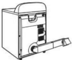
natural_image
Line drawing of a mechanical device with handle and internal components (no text or symbols)
natural_image
Pure architectural line drawing of a staircase and window frame structure without any text or symbols
natural_image
Line drawing of a hand using a wrench to lift a pipe (no text or symbols)
natural_image
Illustration showing two steps of car wheel rim cleaning: one with a black cover, the other with hands holding a mesh cover (no text or symbols)
natural_image
Line drawing of a washing machine with a door open showing internal components (no text or symbols)
- Seleccione ADD APPLIANCE (AÑADIR ELECTRODOMÉSTICO).
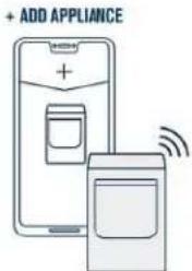
natural_image
Simple line drawing of a screwdriver with no text or symbols
natural_image
Line drawing of a wire crimping tool (no text or symbols)
Pelacables
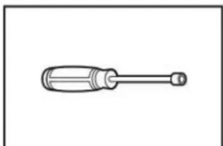
natural_image
Simple line drawing of a screwdriver with a handle and shaft (no text or symbols)
Sacatuercas de 1/4"
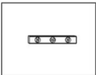
natural_image
Simple diagram with three circular symbols inside a rectangular box (no text or labels)
Nivel
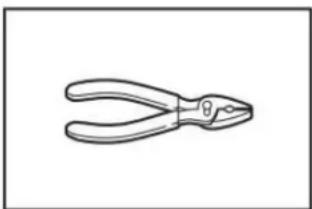
natural_image
Line drawing of a pair of pliers (no text or symbols)
Pinzas

natural_image
Simple line drawing of a tape measure (no text or symbols)
Cinta métrica
natural_image
Simple line drawing of a flat tool with a handle and central slot (no text or symbols)
natural_image
Line drawing of a pair of pliers (no text or symbols)
Tijeras cortachapa
natural_image
Two line drawings of a hand tool: a cylindrical object and a manual tool (no text or symbols)
natural_image
Line drawing of an adjustable wrench (no text or symbols)
natural_image
Two interlocked circular hoses with black connectors (no text or symbols)
natural_image
Illustration of two types of threaded fasteners or bolts, one with hexagonal end caps and the other with coiled bolts (no text or symbols)
natural_image
Simple line drawing of a T-shaped pipe fitting with two side flanges (no text or symbols)
Conector en "Y"
natural_image
Simple line drawing of a ring-shaped object (no text or symbols)
Arandela de goma
natural_image
Simple black curved line with two endpoints, no text or symbols present
natural_image
Coiled black cable or hose with two connectors (no text or symbols visible)
Manguera de entrada de 5' (1,52 m)
natural_image
Technical line drawing of a mechanical housing with mounting holes and internal components (no text or symbols)
natural_image
Line drawing of a front-loading washing machine with ventilation slots and control panel (no text or symbols)
natural_image
Pure electrical circuit lines without any symbols
natural_image
Pure electrical circuit lines without any symbols
natural_image
Technical diagram of an electrical component with labeled parts (no readable text or symbols)
natural_image
Pure electrical circuit lines without any symbols
natural_image
Diagram of an electrical outlet with a coiled cable and a downward arrow indicating a connection (no text or symbols present)
natural_image
Technical line drawing of an electrical socket with coiled tubing and wiring (no text or symbols)
natural_image
Pure electrical circuit lines without any symbols
natural_image
Diagram of a portable electronic device with a coiled cable or hose, showing internal components and a magnified inset (no text or symbols)

natural_image
Line drawing of a mechanical device with a handle and internal components (no text or symbols)
natural_image
Pure technical line drawing of a mechanical assembly without any text, numbers, or symbols
natural_image
Pure technical line drawing of a curved pipe or duct with a vertical support (no text or symbols)
natural_image
Diagram showing pipe fittings and connectors with arrows indicating direction (no text or symbols)
natural_image
Pure diagram of pipe connections without any text, numbers, or symbols
natural_image
Diagram of a hand using a mechanical device to interact with a cable (no text or symbols present)
natural_image
Diagram showing two mechanical assembly steps: one with pipe fittings and valve, the other with a hand adjusting a component (no text or symbols present)
natural_image
Technical line drawing of a mechanical assembly with an inset showing a close-up of a component (no text or symbols present)
natural_image
Pure electrical circuit lines without any symbols
natural_image
Illustration of three different pipe fittings with drops, showing different installation states (no text or symbols present)
natural_image
Diagram of a vehicle exhaust pipe system with valve and valve components (no text or labels)
natural_image
Simple line drawing of a box with a door and arrow indicating left motion (no text or symbols)
natural_image
Line drawing of a hand using a wrench to adjust or install a pipe (no text or symbols present)
natural_image
Illustration showing two steps of car wheel rim installation: one with a circular component, the other with hands holding a closed panel (no text or symbols)
- Cargue la ropa
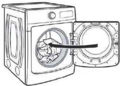
natural_image
Line drawing of a washing machine with an open door showing internal components (no text or symbols)
- Presione START/PAUSE (INICIO/PAUSA)