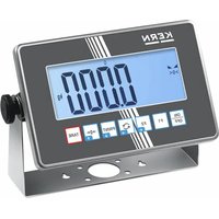
TKXC-TM-A - Electronic scale Kern - Free user manual and instructions
Find the device manual for free TKXC-TM-A Kern in PDF.


| Product type | Indicator for electronic balance |
| Brand | Kern |
| Model | TKXC-TM-A |
| Category | Electronic balance |
| Dimensions (L x D x H) | 232 x 80 x 150 mm |
| Net weight | 1.6 kg |
| Power supply | 100-240 V, 50/60 Hz, 0.4 A, Schuko plug |
| Optional battery | YKR-01, 3.7 V, 3700 mAh, 48 h runtime (backlight off) |
| Display | 6-digit LCD, 48 mm height, backlit |
| Resolution (calibratable) | Single max. 3000 e, Multi Range/Interval 2x3000 e |
| Resolution (non-calibratable) | 999 999 d |
| Calibration classes | III or IIII |
| Weighing ranges | 1 or 2 |
| Weighing units | g, kg, lb, pcs, %, FFA |
| Applications | Weighing, counting, checkweighing |
| IP protection | IP68 |
| Permissible ambient temperature | -10 °C to +40 °C |
| Max. relative humidity | 80 % (non-condensing) |
| Optional interfaces | RS-232, USB, WLAN, Ethernet, Bluetooth, analog (0-10V, 4-20mA) |
| Maintenance and cleaning | Clean with a soft cloth. Do not use high-pressure cleaner. Observe ambient conditions. |
| Safety | Do not use in explosive areas. Disconnect before opening. Use only original KERN parts. |
| Spare parts and repairability | Battery and interface modules available as options. Repair by qualified personnel. |
Frequently Asked Questions - TKXC-TM-A Kern
User questions about TKXC-TM-A Kern
0 question about this device. Answer the ones you know or ask your own.
Ask a new question about this device
Download the instructions for your Electronic scale in PDF format for free! Find your manual TKXC-TM-A - Kern and take your electronic device back in hand. On this page are published all the documents necessary for the use of your device. TKXC-TM-A by Kern.
USER MANUAL TKXC-TM-A Kern
Installationsanleitung Assembly instructions Instructions d'installation
KERN
Typ / Type
Version 1.0
2024-07
KXC
TKXC-TM-A
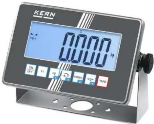
GB Further language versions you will find online under www.kern-sohn.com/manuals
natural_image
Pure diagram of rectangular shapes with dashed outlines and a diagonal line, no text or symbols presentnatural_image
Pure geometric diagram of a rectangular frame with four corner dots, no text or symbols present.3.

HINWEIS
natural_image
Technical line drawing of a device enclosure with mounting flanges and internal wiring (no text or symbols)natural_image
Technical line drawing of a rectangular electronic component with four mounting holes and internal connectors (no text or symbols)natural_image
Technical line drawing of a rectangular electronic component with mounting flanges and internal connectors (no text or symbols)natural_image
Diagram of a cable connector with wires and a directional arrow (no text or symbols)natural_image
Technical line drawing of a rectangular electronic device with mounting holes and a cable (no text or symbols)natural_image
Close-up of a green electronic component with multiple terminal blocks and red indicator lights (no visible text or symbols)natural_image
Pure electrical circuit lines without any symbolsnatural_image
Technical line drawing of a rectangular electronic device with four connectors and a cable inserted (no text or symbols)natural_image
Technical line drawing of an electrical enclosure with wiring and components, no visible text or symbolsnatural_image
Empty rectangular frame with rounded corners (no text or symbols)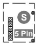
natural_image
Technical line drawing of a rectangular electronic component with mounting flanges and connectors (no text or symbols)natural_image
Technical line drawing of a mechanical or electronic component with mounting flanges and internal components (no text or symbols)natural_image
Diagram of a device panel with cable connectors and a connector, showing no text or symbols.natural_image
Pure electrical circuit lines without any symbolsBeispiel RS-232


flowchart
graph TD
    A["rAnGEs"] --> B["Process Box with Return Icon"]
    B --> C["Output"]
⇒ Mit [↑] oder [↓] zu
→ [→] drücken
flowchart
graph TD
    A["unit"] --> B((Circular icon with refresh arrow))
    B --> C[" "]
    C --> D[" "]
⇒ Mit [↑] oder [↓] zu
→ [→] drücken
flowchart
graph TD
    A[" "] --> B[" "]
    style A fill:#fff,stroke:#000
    style B fill:#fff,stroke:#000
    note right of A: kg
Installation instructions
Display unit
Contents
1 Introduction....4
1.1 General notes on these instructions....4
1.2 Presentation conventions 4
1.2.1 Representations of the text 4
1.2.2 Representations of the device operation.... 5
1.2.3 Binding information 5
1.2.4 Additional information, tips and recommendations.... 5
2 Description of the device 6
2.1 Description of the device 6
2.2 Technical data....6
3 Overview of the device 7
3.1 Keyboard....7
3.2 Adjustment switch 7
4 General safety information....8
4.1 Control on takeover 8
4.2 Observe accompanying documentation 8
4.3 General information on warning notices 8
4.4 Intended use 10
4.5 Improper use 10
4.6 User qualification.... 10
4.7 Ambient conditions.... 10
4.8 Mains connection 10
4.9 Rechargeable batteries and batteries.... 11
4.10 Electrostatic sensitive components 12
5 Assembly, installation and commissioning....13
5.1 Unpacking and checking 13
5.2 Scope of delivery.... 13
5.3 Prepare weighing platform or weighing platform 14
5.4 Open display unit.... 14
5.5 Connect the indicator to a weighing platform or weighing bridge 15
5.6 Install optional battery 19
5.7 Install optional interface modules 21
5.7.1 Circuit board.... 21
5.7.2 Install interface modules 22
5.8 Optional installation of the alibi memory and the real-time clock.... 25
5.9 Close display unit 25
5.10 Mains operation.... 26
5.11 Initial commissioning.... 26
6 Configuration 27
6.1 Switch on.... 27
6.2 Switch off.... 28
6.3 Open service menu 29
6.3.1 Open service menu in non-calibratable mode 29
6.3.2 Open the service menu in calibratable mode 30
6.3.3 Exit service menu.... 30
6.4 Configure weighing parameters 31
6.4.1 Activate calibration capability 31
6.4.2 Activate increased resolution for calibratable devices.... 32
6.4.3 Setting weighing ranges.... 33
6.4.4 Set basic unit.... 33
6.4.5 Set decimal places 34
6.4.6 Set maximum weighing range(s).... 35
6.4.7 Set readability 36
6.5 Carry out linearisation and adjustment.... 37
6.5.1 Linearisation with a weighing range 38
6.5.2 Linearisation with two weighing ranges.... 42
6.5.3 Carry out adjustment.... 46
6.5.4 Perform adjustment with user-defined adjustment weight...... 48
6.5.5 Setting gravitational constants 50
6.6 Initialise alibi memory....52
6.7 Display number of overloads.... 52
6.8 Display device information 53
6.8.1 Display serial number.... 53
6.8.2 Display software version 53
6.8.3 Display software version for calibratable devices.... 54
6.8.4 Display the value of the A/D converter 54
6.9 Restore factory settings.... 56
7 Menu 57
8 Waste disposal....60
9 Errors and faults 62
9.1 Error messages....62
9.2 Malfunctions 63
A1 Declaration of Conformity 64
1 Introduction
1.1 General notes on these instructions
INFORMATION
Read this document completely before installing and configuring the device. Only use the device in accordance with the specifications described in this document. This serves to protect against personal injury and damage to property.
- In this document you will find the necessary information for the correct installation and adaptation of the indicator to the weighing platform or weighing bridge used.
- The operation of the display unit and the adaptation to the working and ambient conditions are described in the operating instructions for the display unit.
- The steps required to install the weighing platform or weighing bridge are described in the relevant installation instructions.
- The necessary steps for the complete installation of interface modules are described in the respective installation instructions. This document only describes the steps for opening the display unit and the intended connection points.
1.2 Presentation conventions
1.2.1 Representations of the text
| Text | Designation |
| • | Enumeration |
| Instruction for action | |
| 1. | Steps in assembly / installation instructions, the sequence of which must be followed |
| 2. | |
| ... | |
| [ ] | Square brackets are used to display buttonsExample: [X] button |
| < > | Angle brackets are used to display content that is shown on the device display (e.g. menu items, parameters, notifications, ...)Example: |
1.2.2 Representations of the device operation
| Symbol | Meaning |
 | Short keystroke |
 | Long button press / press and hold button |
| Display on the scales (example illustration) |
1.2.3 Binding information
Important and binding information describes facts that must be emphasised, which you must take note of and which are always valid (e.g. legal provisions or terms and conditions).
INFORMATION
!
Here you will find important binding information
1.2.4 Additional information, tips and recommendations
i
Additional information, tips and recommendations can be found here
2 Description of the device
2.1 Description of the device
This device is an indicator for connection to a weighing platform or weighing bridge.

Optimum interaction between the components of the weighing system is achieved with a weighing platform or weighing bridge from KERN.
Information on weighing platforms and weighing platforms as well as already configured weighing systems from KERN can be found online at
www.kern-sohn.com
2.2 Technical data
| KERN | KXC |
| Item number / type | TKXC-TM-A |
| Display | 6 LCD digits, digit height 48 mm, backlit |
| Resolution (calibratable) | Single (Max.) 3000 e |
| Multi Range/Multi Interval (Max.) 2x3000 e | |
| Resolution (not calibrated) | 999.999 d |
| Calibration class | III or IIII |
| Weighing ranges | 1 or 2 |
| Numerical steps | 1,2,5,10, n |
| Strain gauge load cells | 87-1227Ω . (minimum/maximum resistance) |
| Applications | Weighing, counting, checkweighing |
| Weighing units | g, kg, lb, pcs, %, FFA |
| Permissible ambient temperature | -10 °C ... + 40 °C |
| Operating temperature range with bat-tery | 0 °C ... + 40 °C |
| Air humidity | max. 80% rel. (non-condensing) |
| Power supply | Input voltage 100 ~ 240 V; 50 / 60 Hz; 0.4 AOvervoltage category IIMains voltage fluctuations ±10 %Schuko plug |
| Battery operation (option)*Values may vary depending on the con- nected measuring cells or interfaces. | Operating time 48 h (backlight off) |
| Operating time 20 h (backlight on) | |
| Charging time approx. 8 h | |
| Optional rechargeable battery YKR-01 3.7 V; 3700 mAh | |
| Display unit dimensions (without holder) | 232 x 80 x 150 (W x D x H) [mm] |
| Net weight (kg) | 1,6 |
| Interfaces (optional) | RS-232, USB device, WLAN, analogue (0-10V, 4-20mA), Ether-net, Bluetooth |
| Altitude metres | Up to 2000 m |
| IP protection | IP 68 |
| Degree of soiling | 2 |
3 Overview of the device
3.1 Keyboard

This document only describes the button functions relevant for configuration. Further functions can be found in the operating instructions for the display unit.
| Button | Designation | Function | Numerical input | |
 | ON/OFF | Switch onSwitch off (long keystroke) | ||
 | F2 | ← | Navigation button ←Menu level backExit menu | Select previous digit |
 | CHANGE | → | Navigation button →Activate menu itemConfirm selection | Select next digit |
 | ↓ | Navigation button ↓Scroll forwards menu item | Decrease flashing digit (0 - 9) | |
 | ZERO | ↑ | Navigation button ↑Scroll backwards menu item | Increase flashing digit (0 - 9) |
3.2 Adjustment switch
Board of the display unit:
Adjustment switch (under the cover)
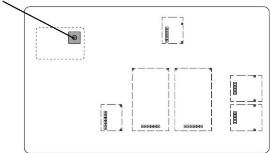
natural_image
Pure architectural floor plan lines without any text, numbers, or symbols4 General safety information
INFORMATION

Read this document completely before installing the device. Only use the device in accordance with the specifications described in this document. This serves to protect against personal injury and damage to property.
4.1 Control on takeover
Please check the packaging immediately upon receipt and the appliance for any visible external damage when unpacking.
4.2 Observe accompanying documentation
Read all the documents supplied with the device completely before using it. Observe all notes and instructions contained therein.
4.3 General information on warning notices
Warnings are used in this document to warn you of possible personal injury or property damage in certain situations.
| Signal word | Description of the |
| DANGER | Failure to observe the instructions will lead directly to serious injury, permanent impairment (e.g. loss of a limb) or death of the user or third parties |
| WARNING | Failure to observe the instructions may result in serious injury, permanent impairment (e.g. loss of a limb) or death of the user or third parties |
| CAUTION | Failure to observe the instructions may result in minor injuries or temporary damage to the user or third parties (e.g. minor cuts) |
| NOTE | Failure to observe the instructions may result in damage to property |
Warning of personal injury:
⚠ SIGNAL WORD

Symbol
Type and source(s) of the hazard
Possible consequence(s) of the hazard
→ Measures to avoid the hazard
Warning of material damage:
NOTE

Measures to prevent damage to property
Symbols in warning notices:
| Symbol | Meaning | |
| Warning signs | Warning signs warn you of dangers that may lead to personal injury. The symbol indicates the type of hazard. | |
 | Indicates general hazards or a danger point | |
 | Warning of electrical voltage | |
 | Warning of flammable substances | |
 | Warning of explosive substances | |
| Command sign | Mandatory signs prescribe measures that you must take to avoid personal injury or damage to property. The symbol indicates the necessary actions or objects to prevent damage. | |
 | Indicates a prescribed action | |
4.4 Intended use
- The indicator is a class III verifiable device and is designed for non-automatic scales and weighing systems with commercially available strain gauge load cells in industrial environments.
- The evaluation unit is designed for displaying, recording, storing, forwarding and analysing measurement data within the approved environmental conditions.
- The analyser may only be operated with original spare parts.
4.5 Improper use
- Never operate the evaluation unit in potentially explosive atmospheres.
- The evaluation unit must not be cleaned with high-pressure cleaners.
- The evaluation unit must not be operated with incompletely connected or damaged weighing platforms.
- This analyser does not comply with the Medical Devices Act (MPG) and is not intended for medical purposes.
4.6 User qualification
Scales or weighing systems using this indicator may only be installed by qualified personnel. The relevant guidelines and regulations for each area of application must be observed.
4.7 Ambient conditions
- The ambient conditions described in the operating instructions must be observed. Please refer to the technical data in the device overview.
- Do not operate the appliance in areas at risk of explosion or in areas at risk of explosion due to gases, vapours, mists or dusts.
4.8 Mains connection
General:
Improper use of electrical appliances can result in them catching fire or the user suffering an electric shock. The following therefore applies to mains-powered devices and their connection:
- Only connect the scales to the mains if the information on the scales (sticker) matches the mains voltage.
- Ensure that the mains plug is accessible at all times.
- Protect the mains plug and the mains cable from contact with liquids.
- Ensure that the mains cable is never pinched or kinked.
- Ensure that the mains cable does not pose a tripping hazard.
- Check the mains cable and mains plug for damage before each use.
4.9 Rechargeable batteries and batteries
General:
Improper use of rechargeable or non-rechargeable batteries can cause them to catch fire, explode, emit toxic vapours or release corrosive liquids. The following therefore applies to rechargeable and non-rechargeable batteries:
- Protect from cold, fire and heat. Observe the technical data regarding the authorised operating temperature ranges.
- Never expose to high pressure or microwaves.
- Do not bring into contact with liquids or chemicals.
- Never bring the electrical contacts of rechargeable batteries and batteries into contact with metal objects or short-circuit them.
- Never modify rechargeable batteries, batteries and chargers.
- Batteries must never be charged.
- Never use or charge a defective, damaged or deformed battery.
Insertion, replacement and storage:
Replace rechargeable batteries and batteries only with types recommended by the manufacturer.
If possible, remove the rechargeable batteries and batteries and store them separately (protected against short circuits) if the scale is not to be used for a longer period of time. Leaking battery fluid could damage the scale.
Charging:
Disconnect the appliance from the power supply immediately if it develops odours, becomes hot, discoloured or deformed. The appliance must then be taken out of service.
If battery fluid escapes:
Liquid can escape from damaged rechargeable batteries and batteries. Please note the following:
- Avoid contact between leaking liquid and your skin, eyes or clothing.
- Wear protective clothing/equipment if you want to touch and remove a defective battery.
- Thoroughly clean any areas of skin or clothing that have come into contact with battery fluid with soapy water and then rinse the affected areas thoroughly with clean water.
- If you get battery fluid in your eyes, rinse your eyes immediately with clean water. Then consult a doctor immediately.
4.10 Electrostatic sensitive components
Electrostatic discharge (ESD) can cause damage to electronic components. Damaged components do not always lead to malfunctions immediately, but sometimes only after some time.
Therefore, take precautions for ESD protection before removing hazardous components from the packaging and carrying out work in the electronics area:
- Ground yourself before touching electronic components (ESD clothing, wristband, shoes, etc.).
- Only carry out work on electronic components at suitable ESD workstations (EPA) with suitable ESD tools (antistatic mat, conductive screwdrivers, etc.).
- Only transport electronic components outside the EPA in suitable ESD packaging.
- Never remove electronic components from their packaging if they are outside the EPA.
5 Assembly, installation and commissioning
INFORMATION

- Always follow the instructions in this manual before starting work.
- The illustrations are examples that may differ from the actual product (e.g. positions of the components).
⚠️ DANGER

Electric shock due to contact with live components
Electric shock leads to serious injury or death
Disconnect the appliance from the mains voltage before opening it.
⇒ Only carry out installation work on devices that are disconnected from the mains voltage.
5.1 Unpacking and checking
Remove all parts of the scope of delivery from the packaging and remove the packaging materials. Then check that all parts of the scope of delivery are present and undamaged.
5.2 Scope of delivery
- Display unit
- Mounting bracket
- Ferrite core
- Operating instructions Display unit
• Installation instructions for display unit
5.3 Prepare weighing platform or weighing platform
The preparation of the weighing platform or weighing bridge, such as unpacking, removing transport locks and levelling, is described in the respective installation instructions. Carry out the steps described there.
5.4 Open display unit
- Disconnect the appliance from the mains voltage.
- Loosen the screws on the back of the display unit.
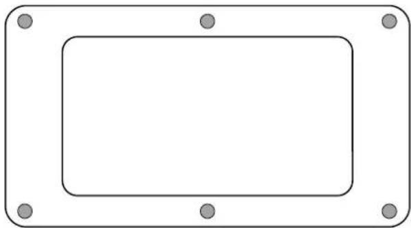
natural_image
Simple line drawing of a rectangular frame with four corner dots (no text or symbols)3.

NOTE
⇒ Make sure that you do not damage any cables (e.g. by tearing them off or pinching them).
Carefully open both halves of the display unit.
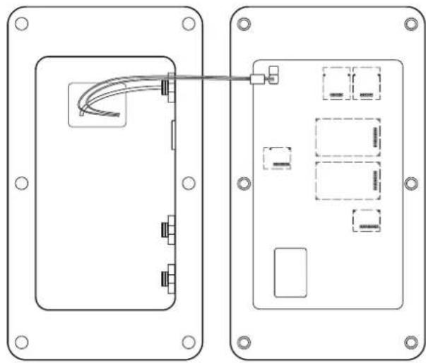
natural_image
Technical line drawing of a device enclosure with mounting flanges and internal wiring (no text or symbols)5.5 Connect the indicator to a weighing platform or weighing bridge
Strip the cable:
- Strip the cable according to the following illustration with the following dimensions.
A = approx. 30 mm
B = approx. 5 mm
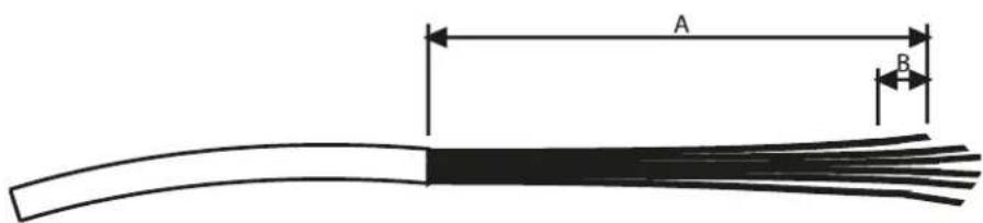
Insert the cable into the display unit:
2.

NOTE
Do not open the pressure equalisation screw on the display unit. This can be recognised by the condensation holes in the screw head. Removing it can lead to moisture in the device and thus to damage.
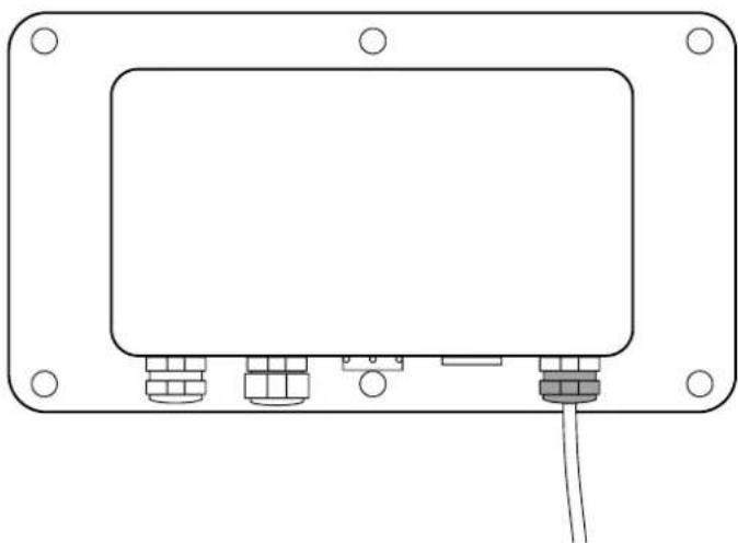
Open the right outer PG screw on the back of the display unit.
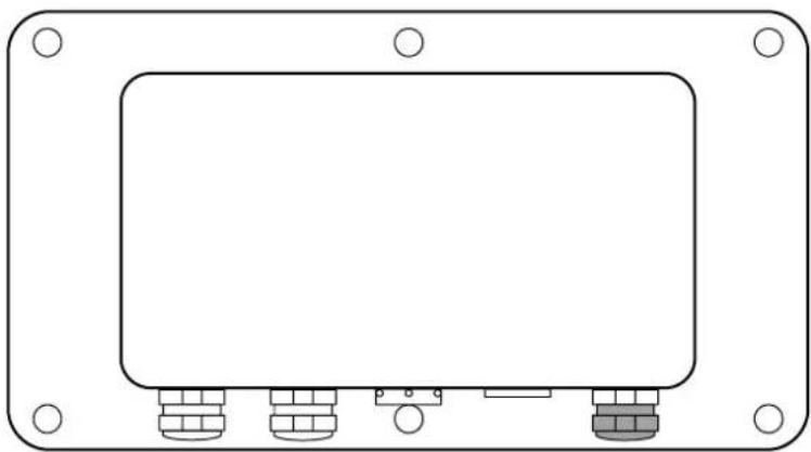
natural_image
Technical line drawing of a rectangular electronic component with mounting holes and three terminal connectors (no text or symbols)-
Remove the sealing pin from the cable gland.
-
Guide the cable with the cable cores through the PG screw.
- Feed the cable through the previously opened cable gland.
Connect the cable to the circuit board:
- Remove the cover over the load cell connection.
flowchart
graph TD
    A["Gray rectangle"] --> B["Box 1"]
    A --> C["Box 2"]
    A --> D["Box 3"]
    A --> E["Box 4"]
    A --> F["Box 5"]
- Connect the wires of the cable to the display unit according to the labelling on the load cell and the circuit board.
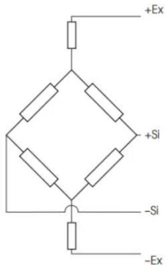
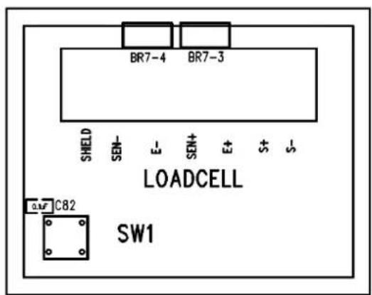
Note:
The evaluation unit is preconfigured for 4-wire. When connecting a 6-wire load cell, the bridges must be cut.
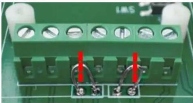
natural_image
Close-up of a green electronic terminal block with multiple terminal holes and red indicator lights (no visible text or symbols)- Attach the ferrite core to the cable.
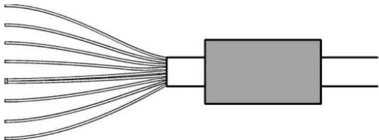
natural_image
Pure electrical circuit lines without any symbols-
Secure the cable to the circuit board with cable ties so that it and the ferrite core cannot slip when closing the display unit.
-
Replace the cover over the load cell connection.
Note: If you want to configure a calibrated device, do not replace the cover until the configuration is complete.
The adjustment switch must be pressed frequently to configure a calibrated device. The adjustment switch is located inside the housing.
Close the screw connection:
11.

NOTE
⇒ Ensure that the load cell cable inside the housing is of a suitable length and cannot be pinched or crushed when closing the housing.
⇒ Tighten the PG screw firmly so that it cannot unscrew again due to vibrations and moisture can penetrate the appliance. Otherwise the appliance could be damaged.
Close the PG screw connection and tighten it firmly from both sides using appropriate open-end spanner (tightening torque = 4 to 5 Nm).
natural_image
Technical line drawing of a rectangular electronic device with four ports and a cable inserted (no text or symbols)5.6 Install optional battery
Risk of fire and explosion due to incorrect handling of rechargeable batteries and batteries
Fire or explosion can lead to serious injuries
Please be sure to observe the notes on rechargeable batteries and batteries in the chapter "Rechargeable batteries and batteries"
⇒ Never recharge batteries. Only rechargeable batteries are suitable for recharging.
- The battery for this device is optional
-
Information on charging the battery (charging time, charging indicator) can be found in the relevant operating instructions for the display device.
-
Open the display unit (see Chap. 5.4).
-
Open the cover in the rear housing section (remove 2x Phillips screw)
-
Insert battery
-
Reattach the cover
- Connect the battery to the plug on the cable
5.7 Install optional interface modules

- This chapter describes how to open and close the display unit to install the optional KUM interfaces.
- The assembly of the KUM interfaces themselves is described in the respective installation instructions.
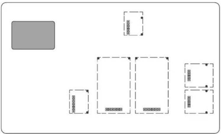
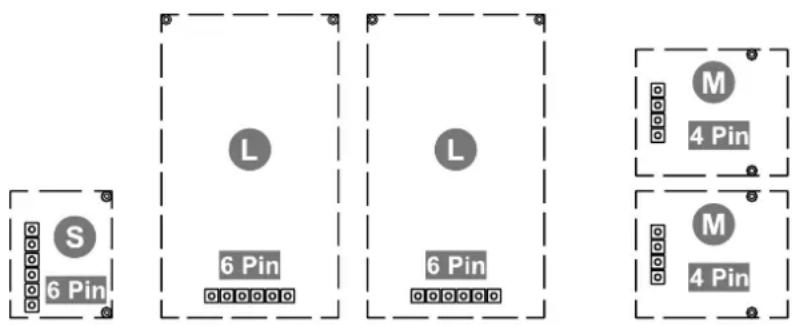
5.7.1 Circuit board
The circuit board of certain display units offers several slots for KERN accessories, with which you can expand the range of functions of your device if required. You can find information on this on our homepage: www.kern-sohn.com
natural_image
Empty rectangular frame with rounded corners (no text or symbols)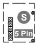
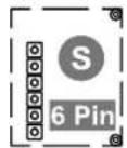
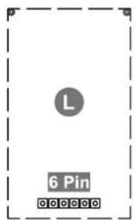
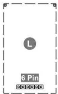
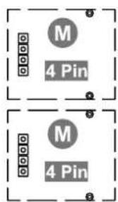
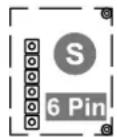
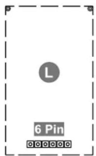
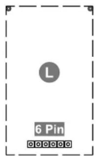
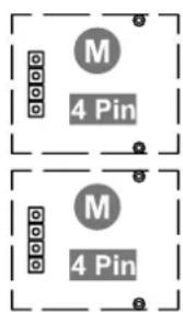
The various slots are shown in the illustration above. There are three slot sizes for optional modules: S, M, L. These have a specific number of pins.
The correct position for your module is determined by the size and number of pins (e.g. size L, 6 pins).
If there are several identical slots on the board, it does not matter which slot you select. The device automatically recognises which module it is.
5.7.2 Install interface modules

For wireless interface modules, the display device only needs to be opened and the respective module attached to the circuit board. These steps are described in the respective installation instructions for the module.
Install the wired interface module on the circuit board:
- Open the display unit (see Chap. 5.4).
- Install the module on the circuit board according to its installation instructions.
Do not open the pressure equalisation screw on the display unit. This can be recognised by the condensation holes in the screw head. Removing it can lead to moisture in the device and thus to damage.
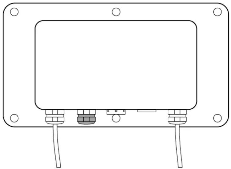
Open the marked PG screw on the back of the display unit.
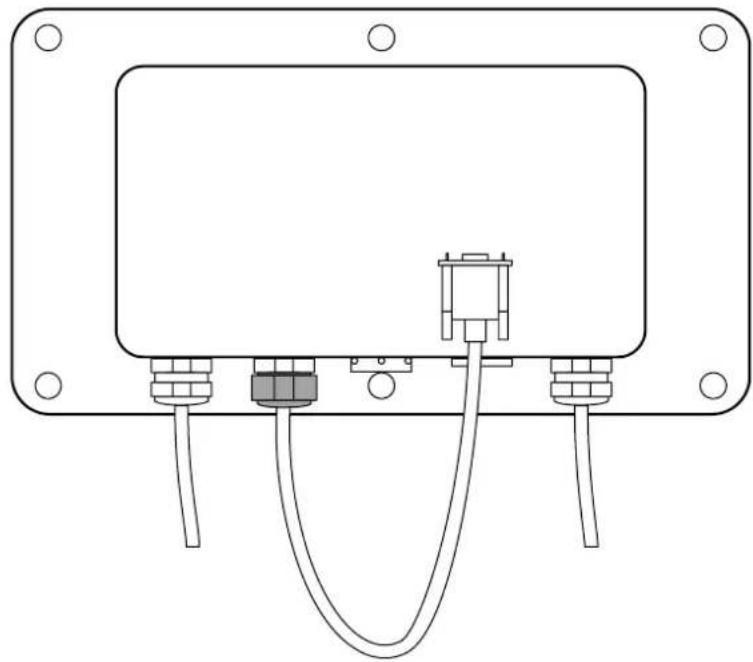
Note: If two wired interfaces are to be installed, the dummy plug (2nd cable gland from the right) can be replaced by a commercially available stainless steel cable gland of size M12. The cable gland must fulfil protection class IP68.
natural_image
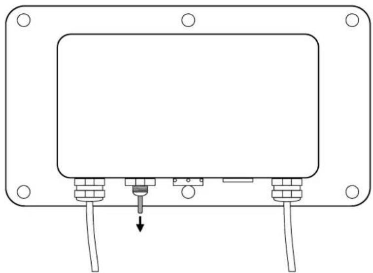
Technical line drawing of a rectangular electronic component with mounting flanges and connectors (no text or symbols)- Remove the sealing pin from the cable gland.
natural_image
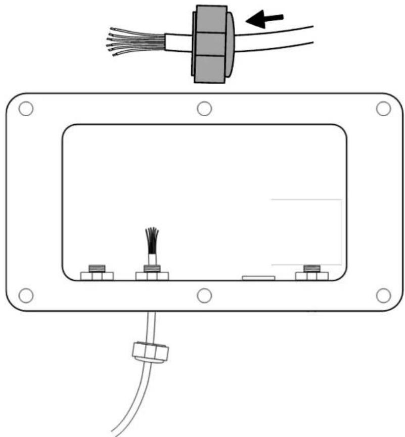
Technical line drawing of a mechanical or electronic component with mounting flanges and internal components (no text or symbols)- Guide the cable through the PG screw in accordance with the module's installation instructions
natural_image
Diagram of a device panel with cable connectors and a connector, showing no text or symbols.Close the screw connection:
6.

NOTE
Ensure that the cable inside the housing is of a suitable length and cannot be pinched or crushed when closing the housing.
Tighten the PG screw to the tightening torque specified below so that it does not unscrew again due to vibrations and moisture cannot penetrate the appliance. Otherwise the appliance could be damaged.
Close the PG screw connection and tighten it firmly from both sides using an appropriate open-end spanner (tightening torque = 4 to 5 Nm).
natural_image
Pure electrical circuit lines without any symbolsExample RS-232
5.8 Optional installation of the alibi memory and the real-time clock

Further information on the alibi memory and real-time clock can be found in the respective installation instructions.
- Open the display unit (see Chap. 5.4).
- Install the alibi memory and real-time clock according to their installation instructions.
-
After installation, it is necessary to initialise the alibi memory and set the date and time.
-
The initialisation of the alibi memory is described in Chap. 6.5.5 is described.
- The date and time settings can be found in the operating instructions for the display unit.
5.9 Close display unit
NOTE

⇒ Make sure that you do not damage any cables (e.g. by tearing then off or pinching them).
→ Make sure that any existing seals are in their intended place.
- Carefully fold both halves of the display unit together.
- Screw the display unit together (tightening torque = 5 Nm ± 5%).

If you want to configure a calibrated device, do not close the display device until the configuration is complete.
The adjustment switch must be pressed frequently to configure a cal brated device. The adjustment switch is located inside the housing.
5.10 Mains operation
INFORMATION
Only use original KERN power supply units
⚠ WARNING

Risk of electric shock and fire due to defective power supply units or short circuit

Electric shock and fire can lead to serious injuries
⇒ Be sure to observe the notes on the power supply unit and mains connection in the "Mains connection" chapter.
Connect the scales to the power supply:
→ Insert the mains plug into the socket
5.11 Initial commissioning
In order to obtain accurate weighing results with electronic scales, the scales must have reached their operating temperature. The scale must be connected to the power supply (mains connection, rechargeable battery or battery) for this warm-up time. Information on the warm-up time can be found in the technical data of the load cell.
6 Configuration
INFORMATION

- Always follow the instructions in this manual before starting work.
- The illustrations are examples that may differ from the actual product (e.g. positions of the components).
To configure the indicator in the service menu, the following configuration data of the weighing system must be known:
- Calibratable or non-calibratable device
- Basic unit
• Number of decimal places displayed
• Maximum loads - Readability
- Number of weighing ranges and scale type (multi-range scale or multi-interval scale)

Further menus and settings (e.g. application menu, setup menu) are described in the operating instructions for the display unit.
6.1 Switch on

Press [ON/OFF].

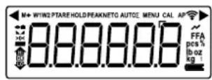
The scales carry out a self-test
Then configure the device uncalibrated or calibrated (see the following chapter)
6.2 Switch off
Switch off the scale in weighing mode:
![ON OFF ⇒ Keep [ON/OFF] pressed ↓ ⇒ The scales switch off](/content/2026/04/714658/images/6d691852840da5e6019123df0db62bea156cda21045087804d6c42d17a52a9de.jpg)
Switch off the scale in the service menu (example starting from menu level 3):
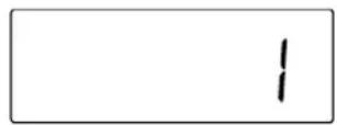
Example: Current parameter setting in third menu level
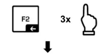
⇒ The scale is located at menu level 3
⇒ Press [←] several times (3 times in this example)
⇒ The scales switch off when the first menu level is exceeded

The scale switches off automatically when you change parameters in the menu and leave the second menu level (when navigating back to level 1).
6.3 Open service menu
6.3.1 Open service menu in non-calibratable mode

The menu can no longer be opened in this way once the calibration capability has been activated.

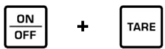

→ Switch on the device
⇒ Press and hold [ON/OFF] and [TARE] at the same time while the self-test is being carried out
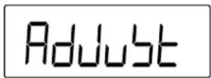
→ Wait until
→ Release buttons
⇒ The device can now be configured in uncalibrated mode
6.3.2 Open the service menu in calibratable mode
INFORMATION

Please note that to configure a calibrated device, the calibration seal must be destroyed and the scale must be recalibrated and sealed by an authorised body (e.g. when converting to another platform). On initial delivery, the evaluation device is not calibrated and not sealed.
DANGER

Electric shock due to contact with live components
Electric shock leads to serious injury or death
Do not touch any live components, only the adjustment switch
NOTE

Please be sure to observe the notes on electrostatically sensitive components in the chapter "Electrostatic sensitive components".
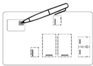


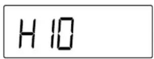
→ Remove the cover of the adjustment switch on the circuit board (for the position of the adjustment switch, see Chap. 3.2)
→ Switch on the appliance and press the adjustment switch
→ Wait until
→ Release buttons
⇒ The device can now be configured in calibrated mode
6.3.3 Exit service menu
The service menu can be exited by pressing the [←] button. To do this, press it repeatedly until the top menu level is reached. After pressing it again, the device switches off.
6.4 Configure weighing parameters

All weighing parameters can be configured in the
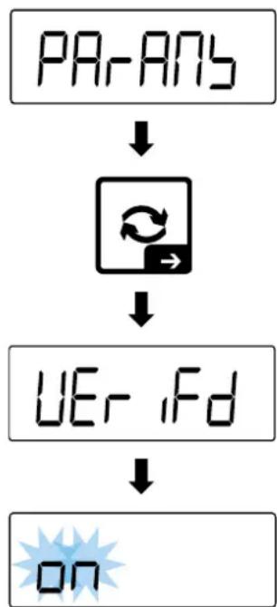
6.4.1 Activate calibration capability

The menu item for activating the calibration capability is only visible in the calibratable mode of the service menu (press the adjustment switch, see Chap. 6.3.2).
flowchart
graph TD
    A["PR-ANS"] --> B["Reset"]
    B --> C["UEr ifd"]
    C --> D["ON"]
Navigate to <Params> with [] or []
⇒ Press [→]
⇒ Select
⇒ Select <□n>
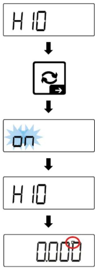
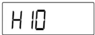
6.4.2 Activate increased resolution for calibratable devices

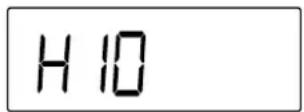
- The increased resolution makes it easier to carry out the conformity assessment by displaying an additional decimal place.
- The query for increased resolution only appears if the device has been set to calibratable and the adjustment switch is pressed again after a restart (press the adjustment switch, see Chap. 6.3.2).
- The increased resolution is displayed after it is activated and the menu is exited. In weighing mode, the 10-fold resolution (additional decimal place in brackets) is then displayed until the next restart.
- As soon as you switch to another menu item and change a parameter, the query disappears from the menu. A new enquiry is then only possible after restarting in calibratable mode and pressing the adjustment switch again.
flowchart
graph TD
    A["H 10"] --> B["返回按钮"]
    B --> C["ON"]
    C --> D["H 10"]
    D --> E["0.000"]
→ Scale displays
→ Press [→]
→ Select
⇒ You can then navigate to another menu item using [↑] or [↓]
⇒ After exiting the menu, the additional decimal place is displayed
6.4.3 Setting weighing ranges
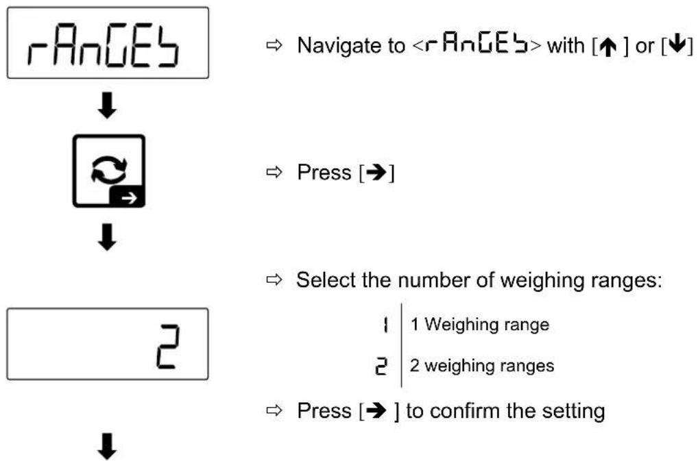
flowchart
graph TD
    A["rAnGE5"] --> B["↓"]
    B --> C["2"]
    D["→"] --> E["→ Press [→"]]
    E --> F["→ Select the number of weighing ranges: 1 Weighing range 2 weighing ranges"]
    F --> G["→ Press [→"] to confirm the setting]
When selecting 2 weighing ranges:
![NuLrnG NuL int | Multi-interval scale NuLrnG | Multi-range scales ⇒ Press [→] to confirm the setting](/content/2026/04/714658/images/1223e60672485617cfca9fd14d3decf6f2b66e791714c1a31c6150849bd5c00b.jpg)
6.4.4 Set basic unit
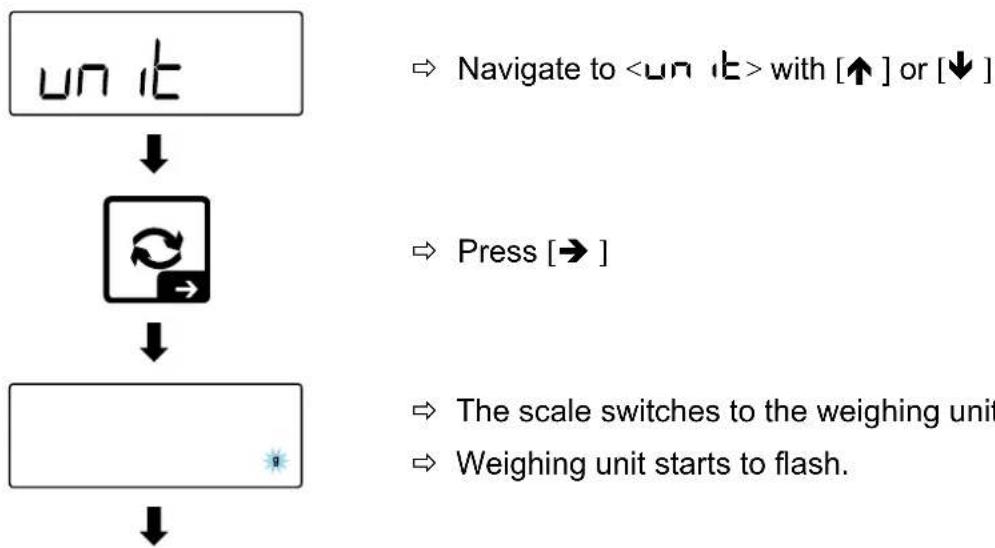
flowchart
graph TD
    A["un it"] --> B["Process Step"]
    B --> C["Scale Switching Unit"]
    C --> D["Weighting Unit Starts to Flash"]
    E["Navigate to <un it> with [↑"] or["↓"]] --> F["Press [→"]]
    G["The scale switches to the weighing unit"] --> H["Weighting Unit starts to flash."]
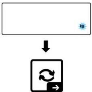
flowchart
graph TD
    A["kg"] --> B((Circular Recycle))
    B --> C["Return Arrow"]
⇒ Use [↑] or [↓] to select the desired weighing unit
⇒ Press [→] to confirm the setting
6.4.5 Set decimal places
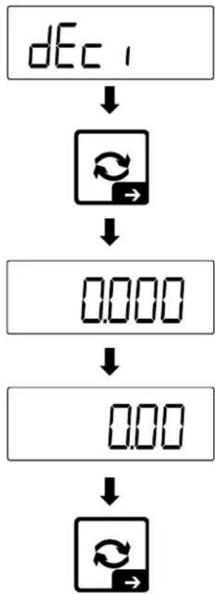
flowchart
graph TD
    A["dEc1"] --> B["Image"]
    B --> C["0.000"]
    C --> D["0.00"]
    D --> E["Image"]
⇒ Navigate to <dEc ↗ with [↑] or [↓]
⇒ Press [→]
Use [] or [] to select the number of decimal places
⇒ Press [→] to confirm the setting
6.4.6 Set maximum weighing range(s)
NOTE

Do not enter a value that exceeds the authorised maximum load of the load cell and the dead load on it. Otherwise, there is a risk that the end user may damage the load cell by applying excessive weights.
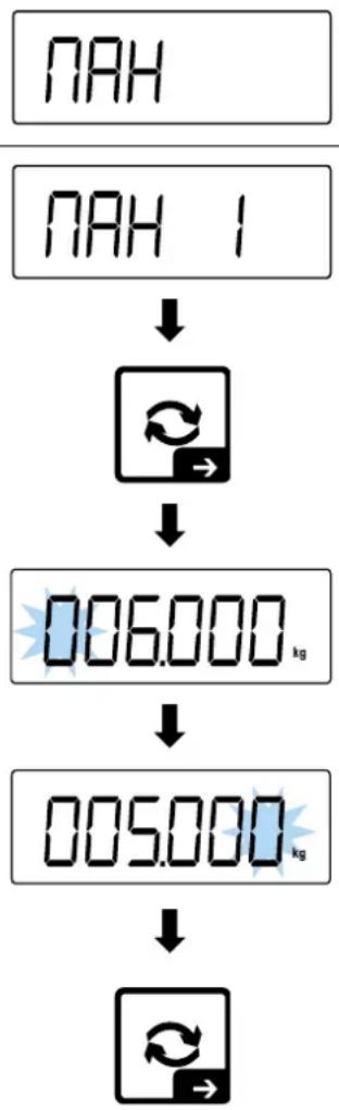
flowchart
graph TD
    A["ПАН"] --> B["ПАН 1"]
    B --> C["返回"]
    C --> D["006.000 kg"]
    D --> E["005.000 kg"]
    E --> F["返回"]
Navigate to < > with [] or [] (For multiple weighing ranges < RAH I> (first weighing range), < RAH2> (second weighing range))
⇒ Press [→]
→ Scale switches to numerical input
Set maximum load (for numerical input, see chapter 3.1)
⇒ Press [→] to confirm the setting
(For other weighing ranges, proceed as described above to set the next maximum load)
6.4.7 Set readability

If you configure a calibratable device, the readability d corresponds to the calibration value e.
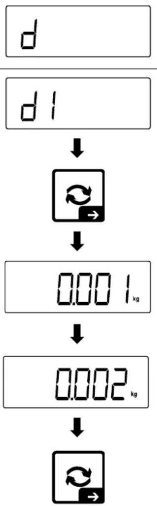
flowchart
graph TD
    A["d"] --> B["d1"]
    B --> C["返回"]
    C --> D["0.001_kg"]
    D --> E["0.002_kg"]
    E --> F["返回"]
⇒ Navigate to
(For multiple weighing ranges
→ Press [→]
⇒ Set the readability with [↑] or [↓]
⇒ Press [→] to confirm the setting
(For other weighing ranges, proceed as described above to set the next readability)
6.5 Carry out linearisation and adjustment
INFORMATION

- During initial commissioning, linearisation must be carried out after setting the weighing parameters.
- The accuracy of the calibration weight must be at least equal to or better than the readability d of the scale.
- The maximum load of the scale must not be exceeded during linearisation and adjustment.
- You can find information on test weights on the Internet at: http://www.kern-sohn.com
NOTE

⇒ For linearisation and adjustment, ensure that the ambient conditions are stable (e.g. avoid vibrations or air currents).
Please note that a warm-up time is required for linearisation and adjustment so that the scale itself is stabilised. The warm-up time can be found in the technical data of the load cell.
→ Make sure that only the calibration weight is on the weighing plate / load receptor during linearisation and adjustment and that no other load is present.
6.5.1 Linearisation with a weighing range
INFORMATION
Carry out user-defined 2-point linearisation and adjustment as close as possible to the maximum load of the scale.

These descriptions apply to the following weighing range settings:
$$ < P A r A N S > \rightarrow < r A n G E S > \rightarrow < 1 > $$
Example of 2-point linearisation:
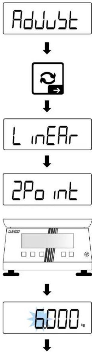
flowchart
graph TD
    A["Adjust"] --> B["Reactor"]
    B --> C["L inEAR"]
    C --> D["2Point"]
    D --> E["KERN Display"]
    E --> F["6000 kg"]
⇒ Navigate to
⇒ Press [→]
Select < L inEAR>
Select the number of linearisation points:
$$ 2 P o i n t $$
2-points (0, user-defined value)
$$ 3 P o i n t $$
3 points (0, centre, max.)
$$ 5 P _ {0} \text { int } $$
5 points (0, 14 max., 12 max., 34 max., max.)
→ Unload the scales / load receptor
⇒ Press [→] to confirm the setting
⇒ Enter user-defined load (for numerical input, see chapter 3.1)

flowchart
graph TD
    A["2Ero"] --> B["..."]
    B --> C["6000 kg"]
    C --> D[" machine "]
    D --> E[" success "]
    E --> F[" "]
→ Press [→]
⇒ The zero point is determined first
⇒ Scale displays
⇒ Scale changes to display the load (in this example load = 6 kg)
⇒ Place the calibration weight in the centre of the weighing plate
⇒ Press [→]
→ Scale performs linearisation
⇒ Scale displays
→ Scale display switches off
Example of 3-point linearisation (similar to 5-point linearisation):
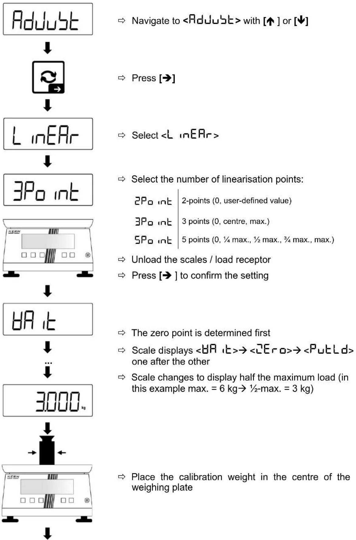
flowchart
graph TD
    A["Adjust"] --> B["Reactor"]
    B --> C["L inEAR"]
    C --> D["3Point"]
    D --> E["8A it"]
    E --> F["..."]
    F --> G["3000 kg"]
    G --> H["Place the calibration weight in the centre of the weighing plate"]

    I["Navigate to <Adjust> with [↑"] or["↓"]] --> J["Press [→"]]
    J --> K["Select <L inEAR>"]
    K --> L["Select the number of linearisation points: 2Point int 2-points (0, user-defined value) 3Point int 3 points (0, centre, max.) 5Point int 5 points (0, ¼ max., ½ max., ¾ max., max.)"]
    L --> M["Unload the scales / load receptor"]
    M --> N["Press [→"] to confirm the setting]

    O["The zero point is determined first"] --> P["Scale displays <8A it> → <Zero> → <PutLd> one after the other"]
    P --> Q["Scale changes to display half the maximum load (in this example max. = 6 kg → ½-max. = 3 kg)"]
    Q --> R["Place the calibration weight in the centre of the weighing plate"]

flowchart
graph TD
    A["Recycle"] --> B["Battery"]
    B --> C["..."]
    C --> D["6000 kg"]
    D --> E["Reactor"]
    E --> F["KERN Display"]
    F --> G["Recycle"]
    G --> H["Battery"]
    H --> I["SuccES"]
    I --> J["End"]
⇒ Press [→]
⇒ Scale performs 12 -max linearisation
⇒ Scale displays
→ Scale switches to displaying the maximum load
⇒ Place the calibration weight in the centre of the weighing plate
⇒ Press [→]
→ Scale performs max linearisation
⇒ Scale displays
→ Scale display switches off
6.5.2 Linearisation with two weighing ranges
INFORMATION
Carry out user-defined 2-point linearisation and adjustment as close as possible to the maximum load of the scale.

These descriptions apply to the following weighing range settings:
$$ < P A r A N S > \rightarrow < r A n G E S > \rightarrow < 2 > $$
Example of 2-point linearisation:

flowchart
graph TD
    A["Adjust"] --> B["Recover"]
    B --> C["L inEAR"]
    C --> D["2Point"]
    D --> E["KERN 15,000 kg"]
⇒ Navigate to
→ Press [→]
Select < L inEAR>
→ Select the number of linearisation points:
$$ 2 P o i n t $$
2-points (0, user-defined value)
$$ 3 P o i n t $$
3 points (0, max. 1, max. 2)
$$ 5 P _ {0} \text { int } $$
5 points (0, 14 Max 2nd, 12 Max 2nd, 34 Max 2nd, Max 2nd)
→ Unload the scales / load receptor
⇒ Press [→] to confirm the setting
Enter user-defined load (for numerical input, see chapter 3.1)

flowchart
graph TD
    A["Raw Material Input"] --> B["Zero"]
    B --> C["..."]
    C --> D["15,000 kg"]
    D --> E["Recycle/Extraction"]
    E --> F["Kern"]
    F --> G["8A t"]
    G --> H["SuccES"]
    H --> I["End"]
→ Press [→]
⇒ The zero point is determined first
⇒ Scale displays
→ Scale switches to the display of the user-defined load
→ Place the calibration weight in the centre of the weighing plate
⇒ Press [→]
→ Scale performs linearisation
⇒ Scale displays
→ Scale display switches off
Example of 3-point linearisation:

flowchart
graph TD
    A["Adjust"] --> B["Linear Array"]
    B --> C["3Point"]
    C --> D["8A bit"]
    D --> E["..."]
    E --> F["6000 kg"]
    F --> G["Output"]
Navigate to
Press [→]
Select
Select the number of linearisation points:
| 2Point | 2-points (0, user-defined value) |
| 3Point | 3 points (0, max. 1, max. 2) |
| 5Point | 5 points (0, 14 Max. 2, 12 Max. 2, 34 Max. 2, Max. 2) |
Unload the scales / load receptor
Press [→]
The zero point is determined first
Scale displays
Scale switches to display of maximum load 1 (in this example max. 1 = 6 kg)
Place the calibration weight in the centre of the weighing plate

flowchart
graph TD
    A["BCS"] --> B["BA LT"]
    B --> C["..."]
    C --> D["15,000 kg"]
    D --> E["Recycle with Bottle"]
    E --> F["KERN"]
    F --> G["Recycle with Bottle"]
    G --> H["BA LT"]
    H --> I["SuccES"]
    I --> J["End"]
→ Press [→]
⇒ Scale performs 12 -max linearisation
⇒ Scale displays
⇒ Scale switches to display of maximum load 2 (in this example max. 2 = 15 kg)
→ Place the calibration weight in the centre of the weighing plate
⇒ Press [→]
→ Scale performs max linearisation
⇒ Scale displays
→ Scale display switches off
6.5.3 Carry out adjustment
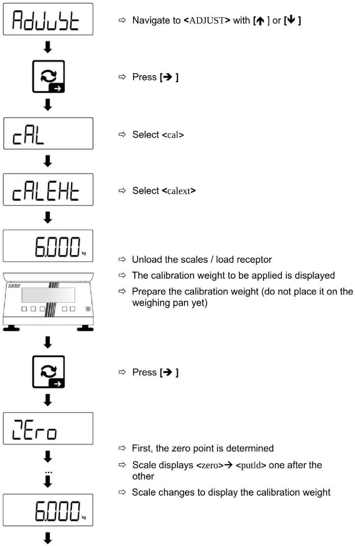
flowchart
graph TD
    A["Adjust"] --> B["Reactor"]
    B --> C["CAL"]
    C --> D["CALEHT"]
    D --> E["6000 kg"]
    E --> F["Zero"]
    F --> G["..."]
    G --> H["6000 kg"]

    I["Navigate to <ADJUST> with [↑"] or["↓"]] --> J["Press [→"]]
    J --> K["Select <cal>"]
    K --> L["Select <calext>"]

    M["Unload the scales / load receptor"] --> N["The calibration weight to be applied is displayed"]
    N --> O["Prepare the calibration weight (do not place it on the weighing pan yet)"]

    P["Press [→"]]
    Q["First, the zero point is determined"] --> R["Scale displays <zero>→ <putld> one after the other"]
    R --> S["Scale changes to display the calibration weight"]
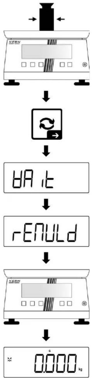
flowchart
graph TD
    A["Device with battery"] --> B["Device with refresh arrow"]
    B --> C["Device with voltage adjustment: BA, t"]
    C --> D["Device with r-ENULD"]
    D --> E["Device with battery and display: KERN"]
    E --> F["Device with 0.000 kg weight"]
Place the calibration weight in the centre of the weighing plate
⇒ Press [→]
→ Wait until
→ Unload the scales / load receptor
→ Scale switches to weighing mode
6.5.4 Perform adjustment with user-defined adjustment weight
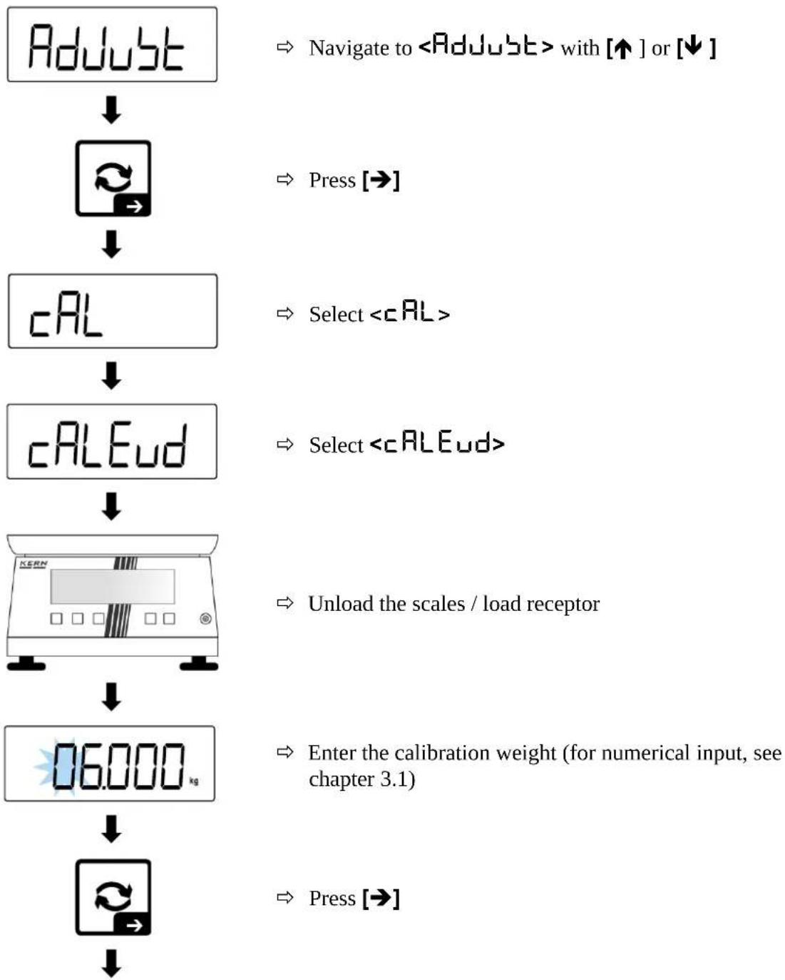
flowchart
graph TD
    A["Adjust"] --> B["Reassembly"]
    B --> C["cAL"]
    C --> D["cALEud"]
    D --> E["KERN"]
    E --> F["06.000 kg"]
    F --> G["Reassembly"]

    style A fill:#f9f,stroke:#333
    style G fill:#f9f,stroke:#333

    note1["Navigate to <Adjust> with [↑"] or["↓"]]
    note2["Press [→"]]
    note3["Select <cAL>"]
    note4["Select <cALEud>"]
    note5["Unload the scales / load receptor"]
    note6["Enter the calibration weight (for numerical input, see chapter 3.1)"]
    note7["Press [→"]]

flowchart
graph TD
    A["Zero"] --> B["..."]
    B --> C["6.000 kg"]
    C --> D["←"]
    D --> E["KERN"]
    E --> F["Recycle icon"]
    F --> G["BA it"]
    G --> H["rENuld"]
    H --> I["..."]
    I --> J["0.000 kg"]
⇒ The zero point is determined first
⇒ Scale displays
→ Scale changes to display the calibration weight
→ Place the calibration weight in the centre of the weighing plate
⇒ Press [→]
→ Wait until
→ Unload the scales / load receptor
→ Scale switches to weighing mode
6.5.5 Setting gravitational constants
INFORMATION

- Only enter the gravitational constants after adjustment and linearisation. The two constants must be known for this.
- The two gravitational constants <GrAAdu> and <GrAu5E> are reset to the default value after readjustment.

After setting the gravitational constants, the weight value is converted and displayed in weighing mode according to the set values.
Set the gravitational constant at the adjustment point:
The calibration location is the location where the scale is calibrated and linearised during configuration. Before setting, find out which value of the constant is valid for you at the place of adjustment and linearisation.

flowchart
graph TD
    A["Adjust"] --> B["Process"]
    B --> C["cAL"]
    C --> D["GrARdu"]
    D --> E["980665"]
    E --> F["Enter the gravitational constant of the adjustment location (for numerical input, see chapter 3.1)"]
    G["Navigate to <Adjust> with [↑"] or["↓"]] --> H["Press [→"]]
    I["Select <cAL>"] --> J["Select <cAL>"]
    K["Select <GrARdu>"] --> L["Select <GrARdu>"]
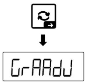
⇒ Press [→]
→ Scale switches back to the menu
Set the gravitational constant at the installation site:
The installation location is the place where the scales will be used. This enables accurate measurements. Find out which value of the constant is valid for the user before setting the scale.
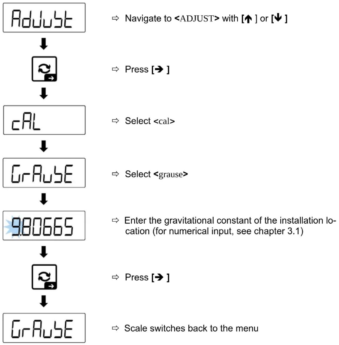
flowchart
graph TD
    A["Adjust"] --> B["Return"]
    B --> C["CAL"]
    C --> D["GrAuse"]
    D --> E["980665"]
    E --> F["GrAuse"]
    A --> G["Navigate to <ADJUST> with [↑"] or["↓"]]
    B --> H["Press [→"]]
    C --> I["Select <cal>"]
    D --> J["Select <grause>"]
    E --> K["Enter the gravitational constant of the installation location (for numerical input, see chapter 3.1)"]
    F --> L["Press [→"]]
    G --> M["Scale switches back to the menu"]
6.6 Initialise alibi memory
⇒ Navigate to <ΠΕΠογ> with [↑] or [↓]
⇒ Press [→]
⇒
⇒ Press [→]
→ Alibi memory is initialised
→ Scale switches back to the menu
6.7 Display number of overloads
In the
6.8 Display device information
6.8.1 Display serial number

The serial number can only be set via KCP. Information on KCP can be found on the KERN homepage: www.kern-sohn.com
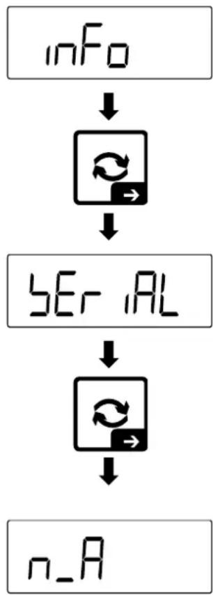
flowchart
graph TD
    A["inF₀"] --> B["返回"]
    B --> C["5Er iAL"]
    C --> D["返回"]
    D --> E["n_A"]
Navigate to < F_0> with [] or []
⇒ Press [→]
⇒ Select
→ Press [→]
⇒ The scale switches to displaying the serial number (no serial number is set on delivery)
⇒ After 3 seconds, the display switches back to
6.8.2 Display software version
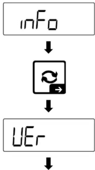
flowchart
graph TD
    A["inF₀"] --> B((Recycle))
    B --> C["UER"]
6.8.3 Display software version for calibratable devices
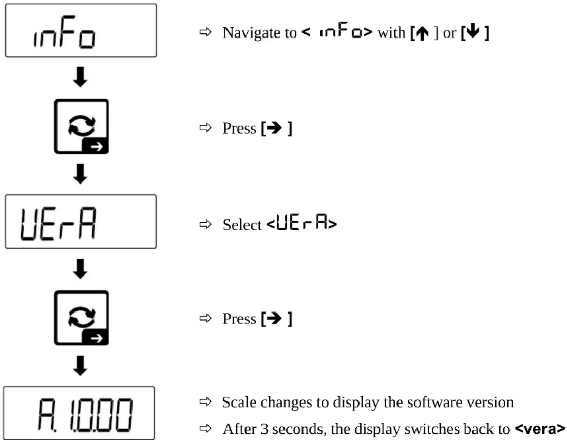
flowchart
graph TD
    A["info"] --> B["返回"]
    B --> C["UER-A"]
    C --> D["返回"]
    D --> E["A.10.00"]
    F["Navigate to <info> with [↑"] or["↓"]] --> G["Press [→"]]
    H["Select <UE-RA>"] --> I["Press [→"]]
    J["Scale changes to display the software version"] --> K["After 3 seconds, the display switches back to <vera>"]
6.8.4 Display the value of the A/D converter
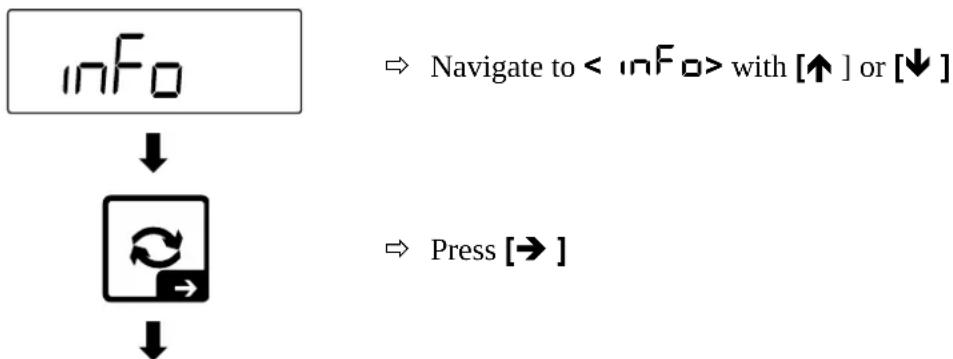
flowchart
graph TD
    A["info"] --> B(( rotating arrow))
    B --> C["Press [→"]]
    D["Navigate to <info> with [↑"] or["↓"]] --> E["-->"]
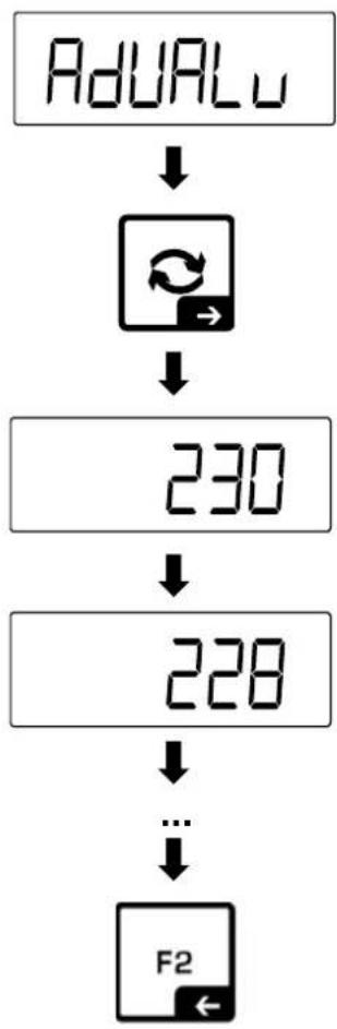
flowchart
graph TD
    A["AduALu"] --> B["Return Loop"]
    B --> C["230"]
    C --> D["228"]
    D --> E["..."]
    E --> F["F2"]
→ Select
→ Press [→]
⇒ Scale changes to display the current value of the A/D converter (dynamic display)
⇒ Press [←] to return to the menu
6.9 Restore factory settings

Restoring the factory settings resets the entire scale. All settings in the service menu and in the operating menus are reset.
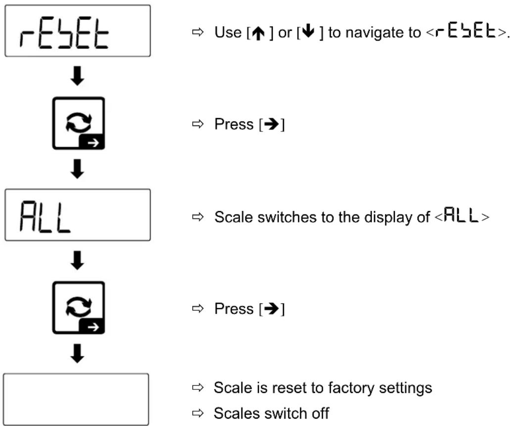
flowchart
graph TD
    A["RESET"] --> B["Process Step"]
    B --> C["ALL"]
    C --> D["Process Step"]
    D --> E["Scale is reset to factory settings\nScales switch off"]
    A --> F["Use [↑"] or["↓"] to navigate to <RESET>.]
    B --> G["Press [→"]]
    C --> H["Scale switches to the display of <ALL>"]
    D --> I["Press [→"]]
7 Menu

- Further menus and settings (e.g. application menu, setup menu) are described in the operating instructions for the display unit.
- Only the first 3 menu levels are listed in the menu overview. Further levels are described in the respective operating steps.
| Level 1 | Level 2 | Level 3 | Description of the |
| H 10 | Setting the increased resolution (only displayed if PA-RA UE-IFd on and then the adjustment switch is pressed again) | ||
| on | Increased resolution activated | ||
| oFF | Increased resolution deactivated | ||
| Adjust | Linearisation and adjustment | ||
| cAL | Adjustment settings | ||
| cALEHT | External adjustment | ||
| cALEud | Adjustment with user-defined weight | ||
| GrARdu | Gravitational constant at the adjustment point (standard: 9.90665) | ||
| GrAuSE | Gravitational constant at the installation site (standard: 9.90665) | ||
| LinEAr | Linearisation settings | ||
| 2Point | 2-point linearisation | ||
| 3Point | 3-point linearisation | ||
| 5Point | 5-point linearisation | ||
| Ero | Not documented | ||
| crEEP | Without function | ||
| params | Weighing parameters | ||
| Verifd | Settings for calibration capa-bility | ||
| On | Activate calibration capabi-lity | ||
| off | Deactivate calibration capa-bility | ||
| ranges | Weighing range setting | ||
| 1 | 1 Weighing range | ||
| 2 | 2 weighing ranges | ||
| unit | Basic unit | ||
| deci | Number of decimal places | ||
| max | Maximum load | ||
| Max1 | Maximum load of the 1st weighing range (with 2 weighing ranges) | ||
| Max2 | Maximum load of the 2nd weighing range (with 2 weighing ranges) | ||
| d | Readability (corresponds to calibration value for calibrat-able devices) | ||
| D1 | Readability 1st weighing range (with 2 weighing ranges) | ||
| D2 | Readability 2nd weighing range (with 2 weighing ranges) | ||
| overl | Information on the number of overloads | ||
| Men | Display of the number of overloads | ||
| Over | Without function | ||
| RENOy | Alibi memory setting | ||
| YES | Initialise memory | ||
| no | Do not initialise memory | ||
| inFo | Device information | ||
| SEr iAL | Display serial number | ||
| UEr | Show software version | ||
| UErA | Display software version for calibratable devices | ||
| AdUALu | Display the value of the A/D converter | ||
| rE5Et | Reset user entries | ||
| ALL | Confirm reset |
8 Waste disposal
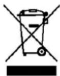
Old appliances and accessories should not be disposed of with household waste.
The operator must dispose of the packaging and appliance in accordance with the applicable national or regional legislation at the place of use.
The device consists of various components and materials, such as
• Electronic components (circuit boards, electrical cables)
- Plastic (e.g. housing parts, covers, ...)
• Metal (e.g. housing parts, screws, ...)
Improper disposal of the appliance can have harmful effects on people and the environment.
Proper and environmentally friendly disposal can prevent harmful effects and recover raw materials.
Disposal of rechargeable batteries and batteries:
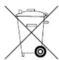
Rechargeable batteries and batteries do not belong in household waste.
The disposal of rechargeable batteries and batteries must be carried out by the operator in accordance with the applicable national or regional law of the place of use.
INFORMATION

The following information is valid for Germany.
In connection with the sale of batteries and rechargeable batteries, we are obliged as a dealer under the Battery Act to inform end users of the following:
- End users are legally obliged to return used batteries and rechargeable batteries.
- After use, batteries and rechargeable batteries can be returned free of charge to municipal collection centres or retailers. The batteries/rechargeable batteries must have reached the end of their normal service life, otherwise precautions must be taken against short circuits.
- The return option is limited to batteries and rechargeable batteries of the type that we carry or have carried in our range and to the quantity that end consumers usually dispose of.
- A crossed-out wheelie bin means that you must not dispose of batteries or rechargeable batteries in household waste. Old batteries or rechargeable batteries may contain harmful substances that can damage people and the environment if not disposed of correctly.
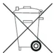
- Batteries containing harmful substances are labelled with a symbol consisting of a crossed-out dustbin and the chemical symbol (Cd = cadmium, Hg = mercury, or Pb = lead) of the heavy metal that is decisive for the classification as containing harmful substances.
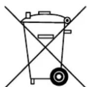
Cd
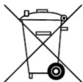
Hg
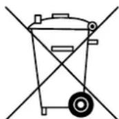
Pb
9 Errors and faults
9.1 Error messages
| Error message | Explanation |
| Eroh i | Zero setting range exceeded at start |
| EroLo | Zero setting range undershot at start |
| L iN it | Zero setting range exceeded during operation |
| undEr2 | Zero setting range undershot during operation |
| unstable | Load unstable |
| ---J | Overload |
| ---- | Underload |
| BronG | Error during linearisation or adjustment |
| LobAt | Battery / rechargeable battery almost empty |
| 5Etrtc | Real-time clock faulty or not setButton cell missing or discharged |
| RunAU | Memory faulty or not recognised |
| no232 | No interface for data output available / selected |
9.2 Malfunctions
| Malfunction | Possible cause |
| Display does not light up / does not switch on | Scale is not switched onMains plug is not plugged in or is defectiveMains voltage has failedBattery is emptyConnection between battery / SMPS board and circuit board faulty |
| Display is incomplete / segments are partially missing | LCD connection is faultyLCD is defective |
| Zero setting ranges exceeded or undershot at start (/) | Load cell cable is not connected correctly |
| Values on the display change constantly or | Weighing plate has contact with foreign objectsLoad cells or display unit connection faultyVibrations of the table / floorDraught / air movementElectromagnetic fields/static charging (choose a different installation location/switch off the interfering device if possible) |
| Display values are not correct | Adjustment or linearisation is not correctorin useScales are not set to zeroScales are not levelStrong temperature fluctuations in the environmentWarm-up time not observed (see weighing platform / weighing bridge documentation)Electromagnetic fields/static charging (choose a different installation location/switch off the interfering device if possible) |
| Display is permanently set to zero | Analogue-digital converter faulty or defectiveLinearisation is not correct |
| The entire weighing range cannot be utilised / display shows overload too early | Apply standard weighing plateProblem with load cell or overload protection |
| Buttons do not work | Keyboard not correctly connected to the circuit boardKeyboard defective. |
| Interface does not work | Internal interface module not installed correctly or defectiveConnection cable not connected correctly or defective |
| Alibi memory does not work | Alibi memory not initialisedAlibi memory module defective |
A1 Declaration of Conformity
INFORMATION
- Other languages of the current EC/EU Declaration of Conformity can be found online at: www.kern-sohn.com/ce
- For verified scales (= conformity-assessed scales), the conformity assessment is included in the scope of delivery.

KERN KXC
Version 1.0 2024-07
1 Introduction......4
natural_image
Pure geometric diagram of a rectangular frame with rounded corners and corner dots (no text or symbols)3.

REMARQUE
natural_image
Technical line drawing of a device enclosure with mounting flanges and internal wiring (no text or symbols)natural_image
Technical line drawing of a rectangular electronic component with four mounting holes and internal connectors (no text or symbols)natural_image
Technical line drawing of a rectangular electronic component with mounting holes and a screw inserted (no text or symbols)natural_image
Diagram of a cable connector with wires and an arrow indicating direction (no text or symbols)natural_image
Technical line drawing of a rectangular electronic device with four connectors and a cable (no text or symbols)natural_image
Close-up of a green electrical terminal block with multiple terminal blocks and red indicator lights (no visible text or symbols)natural_image
Technical line drawing of an electrical enclosure with wiring and components (no text or symbols)natural_image
Technical diagram of an electrical enclosure with wiring and components, no visible text or symbolsnatural_image
Empty rectangular frame with rounded corners (no text or symbols)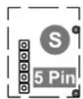
natural_image
Technical line drawing of a rectangular electronic component with mounting flanges and three terminal connectors (no text or symbols)natural_image
Technical line drawing of a mechanical or electronic component with mounting flanges and internal components (no text or symbols)natural_image
Diagram of a cable connector with an arrow indicating direction, showing internal components and wiring (no text or symbols)natural_image
Pure electrical circuit lines without any symbolsExemple RS-232
+

↓
flowchart
graph TD
    A["rAnGEs"] --> B["Process Box"]
    B --> C["Return Arrow"]
flowchart
graph TD
    A[" "] --> B[" "]
    style A fill:#fff,stroke:#000
    style B fill:#fff,stroke:#000
    note right of A: kg
flowchart
graph TD
    A["Recycle"] --> B["Battery"]
    B --> C["..."]
    C --> D["15,000 kg"]
    D --> E["Recycle with battery icon"]
    E --> F["Battery with 'Recycle' icon"]
    F --> G["SuccES"]
    G --> H["End"]
⇒ Appuyer sur [→].
- Installationsanleitung Assembly instructions Instructions d'installation
- KERN
- KXC
- HINWEIS
- Installation instructions
- Display unit
- Contents
- Introduction....4
- Description of the device 6
- Overview of the device 7
- General safety information....8
- Assembly, installation and commissioning....13
- Configuration 27
- Introduction
- General notes on these instructions
- INFORMATION
- Presentation conventions
- Representations of the text
- Representations of the device operation
- Binding information
- Additional information, tips and recommendations
- Description of the device
- Description of the device
- Technical data
- Overview of the device
- Keyboard
- Adjustment switch
- General safety information
- Control on takeover
- Observe accompanying documentation
- General information on warning notices
- Warning of personal injury:
- ⚠ SIGNAL WORD
- NOTE
- Intended use
- Improper use
- User qualification
- Ambient conditions
- Mains connection
- General:
- Rechargeable batteries and batteries
- Charging:
- If battery fluid escapes:
- Electrostatic sensitive components
- Assembly, installation and commissioning
- ⚠️ DANGER
- Electric shock due to contact with live components
- Electric shock leads to serious injury or death
- Unpacking and checking
- Scope of delivery
- Prepare weighing platform or weighing platform
- Open display unit
- Connect the indicator to a weighing platform or weighing bridge
- Strip the cable:
- Insert the cable into the display unit:
- Connect the cable to the circuit board:
- Note:
- Close the screw connection:
- Install optional battery
- Risk of fire and explosion due to incorrect handling of rechargeable batteries and batteries
- Fire or explosion can lead to serious injuries
- Install optional interface modules
- Circuit board
- Install interface modules
- Install the wired interface module on the circuit board:
- Optional installation of the alibi memory and the real-time clock
- Close display unit
- Mains operation
- ⚠ WARNING
- Initial commissioning
- Configuration
- Switch on
- Switch off
- Open service menu
- Open service menu in non-calibratable mode
- Open the service menu in calibratable mode
- DANGER
- Exit service menu
- Configure weighing parameters
- Activate calibration capability
- Activate increased resolution for calibratable devices
- Setting weighing ranges
- Set basic unit
- Set maximum weighing range(s)
- Set readability
- Carry out linearisation and adjustment
- Linearisation with a weighing range
- Example of 2-point linearisation:
- Example of 3-point linearisation (similar to 5-point linearisation):
- Linearisation with two weighing ranges
- Example of 3-point linearisation:
- Carry out adjustment
- Perform adjustment with user-defined adjustment weight
- Setting gravitational constants
- Set the gravitational constant at the adjustment point:
- Set the gravitational constant at the installation site:
- Initialise alibi memory
- Display number of overloads
- Display device information
- Display serial number
- Display software version
- Display software version for calibratable devices
- Display the value of the A/D converter
- Restore factory settings
- Menu
- Waste disposal
- Disposal of rechargeable batteries and batteries:
- Errors and faults
- Error messages
- Malfunctions
- A1 Declaration of Conformity
- KERN KXC
- Introduction......4
- REMARQUE
Brand : Kern
Model : TKXC-TM-A
Category : Electronic scale