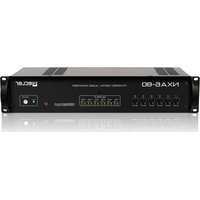
NXA6-80 - Receiver Ecler - Free user manual and instructions
Find the device manual for free NXA6-80 Ecler in PDF.


| Product Type | Amplified receiver with digital processor (DSP) and network management |
| Brand | Ecler |
| Model | NXA6-80 |
| Category | Power amplifier / Digital audio manager |
| Number of channels | 6 amplified channels |
| Output power | 6 × 80 W RMS at 4 Ω (all channels); 65 W RMS at 4 Ω (all channels continuous); 158 W RMS bridged at 8 Ω |
| Amplification | Class D, high efficiency |
| Cooling | Natural convection, fanless (silent operation) |
| Audio inputs | 6 balanced analog inputs on screw terminal blocks (line level) |
| Audio outputs | 6 amplified outputs on screw terminal blocks |
| Operating modes | Independent (SINGLE), parallel (PARALLEL) and bridged (BRIDGE) |
| Network connectivity | Ethernet RJ-45 + RS-232 (3-pin Euroblock); TP-NET protocol |
| Control software | EclerNet Manager (Windows) and UCP (web control panels) |
| GPI remote control | 6 GPI ports 0-10 V DC (terminal blocks), compatible with WpaVOL potentiometers or dry contacts |
| Built-in DSP processor | Per-channel mixer, 8-band parametric equalizer, compressor, crossover (low/high pass filters up to 4th order), delay up to 1000 ms, DUCKER, memories (5 presets) |
| Protection functions | Anti-clipping (anticlip), thermal protection, short-circuit, self-diagnosis with FAULT relay (dry contact NO/NC) |
| Power supply | 115/230 V AC, 47-63 Hz (internal switching, no switch) |
| Power consumption | 144 VA (1/8 power at 4 Ω); 290 VA (1/3 power); < 3 W standby |
| Dimensions (W x H x D) | 482.6 × 88 mm (2U rack); depth 373 mm (handles and knobs excluded) |
| Weight | 10.2 kg |
| Rack mounting | 19 inches, 2 rack units; protective washers included |
| Maintenance and cleaning | Clean with a damp cloth only; do not use solvents or abrasives; do not allow liquid to enter |
| Safety | Grounding mandatory; use by qualified personnel for wiring; do not expose to rain or moisture |
| Repairability | Spare parts available from the manufacturer; maintenance by authorized services; warranty according to Ecler conditions |
| Included accessories | User manual; power cord; rack mounting brackets with screws |
Frequently Asked Questions - NXA6-80 Ecler
User questions about NXA6-80 Ecler
0 question about this device. Answer the ones you know or ask your own.
Ask a new question about this device
Download the instructions for your Receiver in PDF format for free! Find your manual NXA6-80 - Ecler and take your electronic device back in hand. On this page are published all the documents necessary for the use of your device. NXA6-80 by Ecler.
USER MANUAL NXA6-80 Ecler
| Processing: | |
| A/D & D/A DSP Latency | 24 bit, 48kHz. 115dB AKM Codec 32/64 bits 2ms |
| Analog Input headroom: Digital Input attenuator: Input Impedance: Maximum Delay: Delay resolution: | +18 dBV = +21dBu Stepless from -∞ to +0dB Balanced, 22kΩ 1s (343.4m) for each channel 20.8μs (6mm) |
| Compressor / Limiter: Threshold Ratio Attack time Release time | from -36dBV to +18dBV 1:1 to ∞:1 (limiter) Auto or from 0.1ms to 500ms. Auto or from 1ms to 5s. |
| Output peak voltage limiter: Peak voltage upon model (auto settings) | From 10Vpk to 70Vpk |
| High & Low pass Crossover filters | Butterworth in 6/12/18/24dB/oct. Bessel in 12/18/24dB/oct Linkwitz-Riley in 12/24dB/oct. |
| Parametric Eq. types (8 max. per output) | - Bypass / On-Off all channels - Param. Eq. 20Hz-20kHz; -60/+12dB; Q from =.3 to 200 - Low & High Shelf 6/12 dB/oct - Low & High Pass 6/12 dB/oct. - All-Pass 1/2 order |
| Built In signal generator | - Sine (20Hz to 20kHz) - Polarity(10/20Hz to 10/20kHz) - White - Pink |
| Signal Mute Signal Polarity Invert | Yes Yes |
| Connectivity: | - Ethernet Base-Tx 10/100Mb, Auto X-Over, Cat5 - RS232 57600(fixed)-8-N-1-N |
SOFTWARE
| EclerNet Software | Realtime full GUI of all functions and controls thru Ethernet with interactive graphical display Grouping mode channels or devices Automated report generation Remote power on with programmable delay. Up to 256 devices on same net. Autodiscovery devices feature Routing capability through NAT gateways. Real time metering at input/output (DSP) Device “Finder” feature Save & Recall setup and preset functions Firmware update capability thru Ethernet Password protection Default Network configuration: IP: 192.168.0.100 Mask: 255.255.255.0 Gate: 192.168.0.1 UDP Port: 2210 |
| Operating System: | Windows®: XP Prof. (SP3); Vista (SP1); W7(SP1), W8, W10 and W11. |
| Minimum EclerNet System Requirements: | Pentium IV® 2GHz 500MB RAM 100MB HDD free space 1024x768 pixels & 16bits colour display 10/100/1000 Ethernet Network card |
TP-NET PROTOCOL
SOFTWARE
Third-Party NET
USER MANUAL
11 TP-NET PROTOCOL INTRODUCTION
The TP-NET protocol lets a client device (control device) get and/or set the values of several parameters of the EclerNet compatible devices (MIMO and MIMO SG series digital matrices, DUO-NET PLAYER, NXA digital audio manager series, NZA amplifier series, NPA amplifier series, etc.), like volumes, mutes, alarms, etc. It's as well available for eMIMO1616 digital matrix, HUB series digital zoner, MIMO7272DN and MIMO4040CDN digital matrix.
The communication with these digital audio devices can be established using Ethernet and the UDP/IP transport protocol, always by means of the 5800 UDP port.
A second option for this communication is using the RS-232 interface that some of these compatible devices do also have (MIMO series, DUO-NET PLAYER, NXA series, etc.). In this case, the serial connection must fulfil the following specifications:
- Baud rate: 57600 (fixed, no autonegotiation) for all the devices, except for DUO-NET PLAYER, eMIMO1616, HUB series and MIMO4040CDN, which use 115200 baud rate)
Data bits: 8 - Parity: None
- Stop bits: 1
- Flow control: None
In case the Ecler device has an Euroblock connector for the RS-232 interface, the serial cable wiring, from the device's connector to a standard DB9 serial interface connector, must be the following:
| WIRING RS232 - DB9 | |
| RS232 | DB9 |
| Tx | Pin 2 (RxD) |
| Rx | Pin 3 (TxD) |
| Gnd | Pin 5 (Signal Gnd) |
The protocol is simple and direct, making it easy to read, write and modify the generated code. It is based on messages with no begin and end delimiter: each message is self-delimited by the UDP packet size, which is defined with a maximum of 80 characters. All the messages must be written in capital letters.
To let some control systems (like CRESTRON®, EXTRON®, AMX®, RTI®, VITY®, MEDIALON®, etc.) process the messages more easily, the EclerNet device adds the character LF (0x0A) to the end of each message. This way the client can buffer the messages to process them, if it's required. The EclerNet device can also handle several messages received in a single message packet by using the LF delimiter.
The available messages are built with one or more fields separated with blank spaces ( = blank space):
<TYPE> [PARAM1] [PARAM2] [PARAM3] [PARAM4][LF]
The first field (TYPE) defines the message type and then, the required parameters for it (each kind of message requires a given number of parameters). The field TYPE can have these values:
SYSTEM
GET
- SET
INC
DEC
- SUBSCRIBE
- UNSUBSCRIBE
DATA
- ERROR
At the end of this document you'll find all the available messages and their parameters for each model of the EclerNet compatible devices.
The SYSTEM, GET, SET, INC, DEC, SUBSCRIBE & UNSUBSCRIBE messages can be sent from the client to the EclerNet device. The DATA & ERROR messages can be sent from the device to the client. The only exception is the SYSTEM PING message, that is a SYSTEM type message that is sent from the EclerNet device when the initial message from the client to the device was SYSTEM CONNECT PINGPONG.
The communication (using UDP or RS-232) starts when a client sends the message SYSTEM CONNECT to the EclerNet device. As far as the UDP communication requires no connection (unlike the TCP), the EclerNet device stores this client's IP address, and then uses it as the destination IP address for the messages that it generates (DATA & ERROR). After receiving the SYSTEM CONNECT message, the device dumps its entire configuration using several consecutive DATA messages.
Note: if the configuration data dump process (usually a huge list of parameters & values) wants to be avoided after a SYSTEM CONNECT message, a SYSTEM CONNECT ONCE message can be used instead.
The communication can be terminated by two methods:
-
Manually: when the client sends the SYSTEM DISCONNECT message, cancelling all the subscriptions and stopping the DATA & ERROR messages
-
Automatically: in case the initial message was SYSTEM CONNECT PINGPONG and the client didn't get any SYSTEM PONG message in a period longer than 10 seconds (presuming a communication breakdown)
The SET messages don't have an automatic acknowledgement with a DATA message sent from the EclerNet device after it has processed the SET command. The client must update the values itself and must send the needed GET message if it requires confirmation from the device.
NOTES:
- The numerical values are always integer numbers without +, -, comma or dot symbols.
- [PINGPONG] is an optional parameter used to configure the device-client communication with a periodical check, to see whether the client or the device have terminated it. When configured this way, the device sends a SYSTEM PING once per second, and the client must answer with a SYSTEM PONG message. If anyone doesn't get these messages along a 10 seconds period, the communication will be considered terminated.
- [ONCE] is an optional parameter used to start the device-client communication without a full data dump process (usually a huge list of parameters & values).
- &
is a numerical value that identifies one available Preset stored in the EclerNet device's memory. For the NXA and NZA series it can be within the [1..5] range. , y
are numerical values in the [0..100] range that define values in a scale equivalent to [-inf..0] dB. - <GPI> & <GPO> are numerical values. For the NXA series GPI values can be within the [1..4] or [1..6] range, depending on model.
is a numerical value within the [0..100] range that indicates the value of an analogue GPI input. For a digital input only 0 or 100 are the possible values. is a numerical value within the [0..1] range: it can only be 0 or 1 (opened or closed GPO). is a numerical value within the [1..10] range that sets the VU-meter refresh rate, or the number of times the vumeters' values are sent per second (by default = 3). - "Device Name" is the device name inside double quotation marks, to allow for names with blank spaces.
-
is a numerical value for an error code. -
“
” is a text chain inside double quotation marks, containing an error description. is a numerical value that identifies a Virtual Control. - It can be within a [1A..4A] or [1B..4B] range for NXA 4 ch. Mode
irc It can be within a [1A..6A] or [1B..6B] range for NXA 6 ch. Models.
12 NXA DIGITAL AUDIO MANAGER SERIES
IMPORTANT NOTE: The communication must be started with the client sending the first message SYSTEM CONNECT or SYSTEM CONNECT ONCE to the EclerNet device. Otherwise, the commands from the client to the EclerNet device will be ignored. See TP-NET PROTOCOL INTRODUCTION chapter for additional information.
| TYPE | PARAM1 | PARAM2 | PARAM3 | PARAM4 | DESCRIPTION |
| SYSTEM | CONNECT | [MASTER] | [PINGPONG] | [ONCE] | • MASTER: this parameter, applied in SYSTEM CONNECT, is used to disconnect all clients currently connected to the device, releasing all open and not correctly closed connections, opening a new connection. In this way we guarantee that the client that has set the MASTER option is the only one connected by TP-NET to the device. • PINGPONG: this parameter can be used with the MASTER parameter, the difference is that this parameter performs a periodic check to see if the communication is still open (PING PONG) or if after 10 seconds with no response, the communication has ended (PING). • ONCE: this parameter is used to prevent the device status dump. |
| DISCONNECT | Cancel subscriptions and terminates communication | ||||
| SUBSCRIPTION_RATE | Alive message from device | ||||
| PING | Alive message from device | ||||
| PONG | Alive ACK message from client | ||||
| GET | ALL | Dumps current device status (with DATA messages) | |||
| POWER | Gets the Device Power status | ||||
| PRESET | Gets the current PRESET | ||||
| OLEVEL | Gets the current LEVEL of an Output Channel | ||||
| XLEVEL | Gets the current LEVEL of a Matrix point | ||||
| OMUTE | Gets the current MUTE status of an Output Channel |

ecler
| XMUTE | <Input Channel> | <Output Channel> | Gets the current MUTE status of a Matrix Point | ||
| OVU | <Output Channel> | Gets the VU-meter value of an Output Channel | |||
| ALARM_PROTECT | <Output Channel> | Gets the Protect alarm status of an Output Channel | |||
| ALARM_FAULT | <Output Channel> | Gets the self-diagnosis system alarm status of an Output Channel | |||
| INFO_NAME | Gets the Device Name | ||||
| INFO_MODEL | Gets the Device Model | ||||
| INFO_VERSION | Gets the Firmware Version | ||||
| INFO_MAC | Gets the Device MAC address | ||||
| VIRTUAL_CONTROL | <Virtual Control> | Gets the Virtual Control value | |||
| TYPE | PARAM1 | PARAM2 | PARAM3 | PARAM4 | DESCRIPTION |
| SET | POWER | ON/OFF | Sets the Device Power status | ||
| PRESENT | <Preset Number> | Sets the current PRESET | |||
| OLEVEL | <Output Channel> | <Level> | Sets the current LEVEL of an Output Channel | ||
| XLEVEL | <Input Channel> | <Output Channel> | <Level> | Sets the current LEVEL of a Matrix point | |
| OMUTE | <Output Channel> | YES/NO | Sets the current MUTE status of an Output Channel | ||
| XMUTE | <Input Channel> | <Output Channel> | Sets the current MUTE status of a Matrix Point | ||
| VIRTUAL_CONTROL | <Virtual Control> | <Value> | Sets the Virtual Control value (Value can range from 1 to 100) | ||
| INC | OLEVEL | <Output Channel> | <Value> | Increases the current LEVEL of an Output Channel by Value (Value can range from ±1 to ±100) | |
| XLEVEL | <Input Channel> | <Output Channel> | <Value> | Increases the current LEVEL of a Matrix point by Value (Value can range from ±1 to ±100) | |
| DEC | OLEVEL | <Output Channel> | <Value> | Decreases the current LEVEL of an Output Channel by Value (Value can range from ±1 to ±100) | |
| XLEVEL | <Input Channel> | <Output Channel> | <Value> | Decreases the current LEVEL of a Matrix point by Value (Value can range from ±1 to ±100) | |
| SUBSCRIBE | ALL | Subscribes to all VU-meters | |||
| OVU | <Output Channel> | Subscribes to an Output Channel VU-meter | |||
| UNSUBSCRIBE | ALL | Unsubscribe to all VU-meters | |||
| OVU | <Output Channel> | Unsubscribe to an Output Channel VU-meter | |||
| DATA | POWER | ON/OFF | Shows the Device Power status | ||
| PRESENT | <Preset Number> | Shows the current PRESET | |||
| OLEVEL | <Output Channel> | <Level> | Shows the current LEVEL of an Output Channel | ||
| XLEVEL | <Input Channel> | <Output Channel> | <Level> | Shows the current LEVEL of a Matrix point | |
| OMUTE | <Output Channel> | YES/NO | Shows the current MUTE status of an Output Channel | ||
| XMUTE | <Input Channel> | <Output Channel> | YES/NO | Shows the current MUTE status of a Matrix point | |
| VIRTUAL_CONTROL | <Virtual Control> | <Value> | Shows the Virtual Control value | ||
| OVU | <Output Channel> | <Pre Vumeter Level> | <Post Vumeter Level> | Shows the VU-meter value of an Output Channel | |
| ALARM_PROTECT | <Output Channel> | ON/OFF | Shows the Protect alarm status of an Output Channel | ||
| ALARM_FAULT | <Output Channel> | ON/OFF | Shows the self-diagnosis system alarm status of an Output Channel | ||
| INFO_NAME | " <Device Name>" | Shows the Device Name | |||
| INFO_MODEL | <Device Model> | Shows the Device Model | |||
| INFO_VERSION | <Firmware Version> | Shows the Firmware Version | |||
| INFO_MAC | <Device MAC address> | Shows the Device MAC address | |||
| ERROR | <Error ID> | " <Error Description>" | Informs about an error |
Note: INC and DEC commands are replied with a DATA command from the device with the resulting LEVEL value, after it has been increased or decreased. When the INC or DEC command tries to adjust a LEVEL value beyond its minimum or maximum limits, no reply (DATA command) will be produced.
13 ERROR CODES FOR ECLERNET DEVICES
13.1 COMMON ERROR CODES (to all EclerNet - TP-NET compatible devices)
| ERROR ID | DESCRIPTION |
| 0 | TPNET_ERROR_NONE = 0, |
| 1 | TPNET_ERROR_INVALID_FIELD_TYPE, |
| 2 | TPNET_ERROR_INVALID_FIELD_PARAM1, |
| 3 | TPNET_ERROR_INVALID_FIELD_PARAM2, |
| 4 | TPNET_ERROR_INVALID_FIELD_PARAM3, |
| 5 | TPNET_ERROR_INVALID_FIELD_PARAM4, |
13.2 NXA SERIES SPECIFIC ERROR CODES
| ERROR ID | DESCRIPTION |
| 6 | UDP_ERROR_TIMEOUT_PONG, |
| 7 | UDP_ERROR_connect_while_CONNECTED, |
| 8 | UDP_ERROR_DISCONNECT WHILE_UNCONNECTED, |
| 9 | UDP_ERROR_INVALID_CLIENT_IP, |
| 10 | UDP_ERRORMESSAGE_TOO_long, |
| 11 | UDP_ERROR_UN SUPPORTED_MESSAGE, |
| 12 | UDP_ERROR_UN SUPPORTED_PRESET_NUMBER, |
| 13 | UDP_ERROR_UN SUPPORTED_INPUT_CHANNEL_NUMBER, |
| 14 | UDP_ERROR_UN SUPPORTED_OUTPUT_CHANNEL_NUMBER, |
| 15 | UDP_ERROR_UN SUPPORTED_GPI_NUMBER, |
| 16 | UDP_ERROR_UN SUPPORTED_GPO_NUMBER, |
| 17 | UDP_ERROR_INVALID_LEVEL_VALUE, |
| 18 | UDP_ERROR_INVALID_RATE_VALUE, |
| 19 | UDP_ERROR_GPO_VALUE, |
| 20 | UDP_ERROR_MAX_clients_REACHED, |
| 21 | UDP_ERRORMASTER_MODE, |

ecler




Brand : Ecler
Model : NXA6-80
Category : Receiver