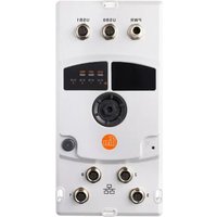
AE2400 - Network gateway IFM - Free user manual and instructions
Find the device manual for free AE2400 IFM in PDF.


User questions about AE2400 IFM
0 question about this device. Answer the ones you know or ask your own.
Ask a new question about this device
Download the instructions for your Network gateway in PDF format for free! Find your manual AE2400 - IFM and take your electronic device back in hand. On this page are published all the documents necessary for the use of your device. AE2400 by IFM.
USER MANUAL AE2400 IFM
Operating instructions
moneo|edge
Gateway
AE2400
Contents
1 Preliminary note 3
1.1 Legal and copyright information 3
1.2 Symbols used 3
1.3 Warnings.... 3
1.4 Applicable documents.... 3
1.5 Change history 4
2 Safety instructions.... 5
2.1 Safety symbol on the device 5
2.2 Cybersecurity 5
3 Intended use.... 7
4 System description 8
4.1 Ethernet ports 8
4.2 USB ports 8
4.3 Status LEDs 8
4.4 Voltage supply 8
4.5 Operating software 9
5 Installation.... 10
5.1 Overview.... 10
5.2 General installation instructions 10
5.2.1 Mounting surface 10
5.2.2 Pressure compensation element.... 11
5.2.3 UV protection 11
5.2.4 Heat dissipation 11
5.2.5 Installation position 11
5.3 Installing the device.... 12
6 Electrical connection.... 13
6.1 Overview.... 13
6.2 General wiring information 13
6.2.1 General notes on wiring 13
6.3 Ethernet ports 14
6.4 USB ports 14
6.5 Functional earth 16
6.6 Voltage supply 16
7 Operating and display elements 18
7.1 LEDs.... 18
7.1.1 Status 18
7.1.2 Ethernet 18
8 Set-up.... 19
8.1 Getting started 19
9 Troubleshooting 21
9.1 Status LEDs 21
10 Maintenance, repair and disposal 22
10.1 Battery change 22
10.2 Cleaning the housing surface 23
10.3 Repair 23
10.4 Disposal 23
10.5 Updating the system software.... 23
1 Preliminary note
You will find instructions, technical data, approvals and further information using the QR code on the unit / packaging or at documentation.ifm.com.
1.1 Legal and copyright information
© All rights reserved by ifm electronic gmbh. No part of these instructions may be reproduced and used without the consent of ifm electronic gmbh.
All product names, pictures, companies or other brands used are the property of the respective rights owners.
1.2 Symbols used
√ Requirement
Instructions
Reaction, result
[...] Designation of keys, buttons or indications
→ Cross-reference

Important note
Non-compliance may result in malfunction or interference.

Information
Supplementary note
1.3 Warnings
Warnings indicate the possibility of personal injury and damage to property. This enables safe product handling. Warnings are graded as follows:

WARNING
Warning of serious personal injury
▷ If the warning is not observed, fatal and serious injuries are possible.

CAUTION
Warning of minor to moderate personal injury
▷ If the warning is not observed, minor to moderate injuries are possible.
ATTENTION
Warning of damage to property
▷ If the warning is not observed, damage to property is possible.
1.4 Applicable documents
- Data sheet
- Quick reference guide
-
Operating instructions (supplement) - Cybersecurity
-
moneo|Appliance Management System (AMS) software manual
- ifm moneo online help
1.5 Change history
| Issue | Subject | Date |
| 00 | New creation of the document | 07 / 2024 |
| 01 | Added: Notes on external wiring, General wiring information (→ □ 13)Corrections: Use in mobile machines, Intended use (→ □ 7) | 01 / 2025 |
| 02 | Added: Notes on the cULus scope of validity | 03 / 2025 |
2 Safety instructions
- The unit described is a subcomponent for integration into a system.
- The system architect is responsible for the safety of the system.
-
The system architect undertakes to perform a risk assessment and to create documentation in accordance with legal and normative requirements to be provided to the operator and user of the system. This documentation must contain all necessary information and safety instructions for the operator, the user and, if applicable, for any service personnel authorised by the architect of the system.
-
Read this document before setting up the product and keep it during the entire service life.
- The product must be suitable for the corresponding applications and environmental conditions without any restrictions.
- Only use the product for its intended purpose (→ Intended use).
- If the operating instructions or the technical data are not adhered to, personal injury and/or damage to property may occur.
- The manufacturer assumes no liability or warranty for any consequences caused by tampering with the product or incorrect use by the operator.
- Installation, electrical connection, set-up, operation and maintenance of the product must be carried out by qualified personnel authorised by the machine operator.
- Protect units and cables against damage.
- Replace damaged units, otherwise the technical data and safety will be impaired.
- Observe applicable documents.
2.1 Safety symbol on the device

Safety symbol on the device:
▶ Adhere to the operating instructions for the safe operation of the device.
2.2 Cybersecurity
Installation
The device is suitable for operation in a secure environment according to IEC 62443-1-1.
The device was designed for operation behind a firewall.
▶ Carry out a risk assessment of the system according to IEC 62443-1-1.
▶ Take measures to ensure physical security.
User and rights management
▶ Only assign the user rights required according to the risk assessment.
▶ When setting up user accounts, observe the specifications of your company's security policy.
▶ Change default passwords immediately during installation / initial set-up.
Operation
▶ Only use communication protocols with sufficiently secure encryption technologies.
▶ Observe the security functions described in the product documentation and the recommendations for their use.
Maintenance
▶ Regularly check whether software updates are available for the device.
- ▶ Back up system configuration and system data in accordance with your company's change management processes.
▶ Always reset the system settings to the factory settings before decommissioning the device.
▶ Ensure that no sensitive information can fall into unauthorised hands.
Decommissioning
3 Intended use
The device serves as a gateway for transferring process data, status information and diagnostic information between the Operational Technology (OT) and Information Technology (IT) levels.
The system software moneo|Appliance Management System and ifm moneo|Cloud are pre-installed on the device.
Permitted use:
• in mobile machines (cabin)
• in industrial environments as a fixed device
• in wet environments
For the cULus scope of validity:
Prohibited use:
• in mobile applications
4 System description
4.1 Ethernet ports
The device has 4 Ethernet ports.
Ethernet port ETH0 is used only as a service interface for setting up the device. For configuration, port ETH0 must be connected directly to a PC / laptop.
- When an Ethernet cable is connected, the interface acts as a DHCP client and attempts to obtain a valid configuration from a DHCP server on the network.
- If a valid configuration cannot be obtained within 5 seconds, a DHCP server is activated on the interface (IP address: 10.0.0.1, network mask: 255.255.255.0). The server assigns a valid configuration to exactly one DHCP client accessible in the network (IP address: 10.0.0.10, network mask: 255.255.255.0).
- The DHCP server is deactivated after 50 seconds; the IP configuration is static (IP address: 10.0.0.10, network mask: 255.255.255.0).
The device is connected to the OT network structure via Ethernet port ETH1. The connection is used for communication with devices with ifm IoT Core (e.g. IO-Link master) and the connected sensors.
The device is connected to the IT network structure via Ethernet port ETH2. The connection is used for communication with cloud systems.
Ethernet port ETH3 is deactivated and has no function.
Factory settings:
| Property | Ethernet port | |||
| ETH0 | ETH1 | ETH2 | ETH3 | |
| Addressing | mode-dependent | static | DHCP | deactivated |
| IP address | (10.0.0.1) | 192.168.0.100 | automatic | |
| Subnet mask | (255.255.255.0) | 255.255.255.0 | automatic | |
| Network gateway | -- | automatic | ||
4.2 USB ports
The device has 2 USB ports (M12, USB 2.0). Additional devices can be connected via the USB ports.
Supported device types:
- USB storage media
4.3 Status LEDs
The device has 3 LEDs.
The LEDs show the current system status and indicate error states.
4.4 Voltage supply
Depending on the operating conditions, the device can be connected to the voltage supply using the following methods:
• Supply via on-board systems (via a battery) with 12 V DC / 24 V DC nominal voltage
• Supply via PELV according to the technical data

▶ Do not use both methods simultaneously to supply the device.
4.5 Operating software
The device provides the following software components:
- Setup wizard (part of AMS) for initial setup of the device and integration into the moneo|cloud
- moneo|Appliance Management System (AMS) for basic configuration and maintenance of the device hardware
- ifm moneo|Cloud for the local configuration of data sources and the connection of further cloud target systems via moneo|edge
Connect
5 Installation
5.1 Overview

1: Upper oblong hole (horizontal)
2: Pressure compensation element
3: Right oblong hole (vertical)
4: Lower oblong hole (horizontal)
5: Left oblong hole (vertical)
5.2 General installation instructions
The following applies to all types of mounting:
The responsibility for the compliance with the requirements concerning mounting of the device in the application with regard to shock, vibration, acceleration and weight lies with the system architect.
5.2.1 Mounting surface
The housing must not be exposed to any torsional forces or mechanical stress.
▶ Use suitable compensating elements if there is no flat mounting surface available.

5.2.2 Pressure compensation element
The device is equipped with a pressure compensation element.
ATTENTION
Sealing of the ventilation ducts of the pressure compensation element with elastic materials
▷ Damage to the device
▶ Do not use any sealing materials in the area around the pressure compensation element.
5.2.3 UV protection
The device meets the requirements for methods of exposure to laboratory light sources and weathering according to DIN EN ISO 4892-2. Test criteria: procedure A, cycle 1: test duration 1000 h, without affecting the functioning.
Additional measures to protect the device from UV radiation (e.g. shading, UV filter) are required to ensure the expected service life when used permanently outdoors.
▶ If necessary, protect the device from UV radiation.
▶ Check the suitability of the selected UV protection and adapt it to the system's area of application if necessary.
5.2.4 Heat dissipation
The device can become very hot during operation. Heat is dissipated via the back of the device. The distance between the back of the device and the mounting surface allows sufficient air flow to dissipate the heat.
ATTENTION
Blockage of the air flow
▷ Damage to the device
▶ During installation, ensure sufficient distance between the back of the device and the mounting surface.
▶ Observe the notes on the mounting surface!
5.2.5 Installation position
▶ In wet environments, install the device in such a way that no liquids can collect in the area of the connectors.
5.3 Installing the device
ATTENTION
Contact corrosion between the mounting screws and the housing
▷ Damage to the device
▶ Do not use stainless steel screws or nickel-plated screws.
▶ Use zinc-plated screws.
▶ In very corrosive environments (e.g. extremely salty air), use screws with surface finishing on a zinc/nickel basis with thick-film passivation and sealing.
▶ Install device.
▶ For mounting on a flat surface, use the upper horizontal oblong hole and the two vertical oblong holes.
▶ For mounting on an industrial aluminium profile, use the two horizontal oblong holes at the top and bottom.
▶ Use galvanised M5 screws with washers or M5 screws with pressed-on washer for fastening. Tightening torque: 3 ± 0.5 Nm
6 Electrical connection
6.1 Overview

1: Voltage supply
2: USB port USB0
3: USB port USB1
4: Ethernet port ETH0
5: Ethernet port ETH1
6: Ethernet port ETH3 – without function
7: Ethernet port ETH2
8: FE connection
6.2 General wiring information
The unit must be connected by a qualified electrician.
▶ Observe the national and international regulations for the installation of electrical equipment.
By means of basic insulation according to EN61010-1, the circuits are isolated from each other and from device surfaces that could be touched (secondary circuit with max. 32 V DC, supplied from mains circuit up to 300 V overvoltage category II).
The external wiring has to be carried out in a way that ensures the required separation from other circuits.
The supply is connected to the FE connection of the device via EMC interference suppression capacitors and in parallel with high impedance.
The Ethernet circuits are connected to the FE connection of the device via EMC interference suppression capacitors.
6.2.1 General notes on wiring
The threaded connections in the device correspond to the M12 standard. To ensure compliance with the specified protection rating, only cables that comply with this standard may be used. In the case of self-assembled cables, the system manufacturer is responsible for the protection rating.
▶ Use connectors with gold-plated contacts.
▶ During installation, place the connectors vertically so that the coupling nut will not damage the thread.
▶ Observe the coding of the connectors during installation.
▶ Provide all outgoing cables with suitable strain relief after a maximum of 400 mm. Observe the minimum bending radius of the cables ( → information from the cable manufacturer).
ATTENTION
No protection rating / no protection of the contacts without mounted connectors / protective caps.
▷ Inadmissible soiling / moisture possible.
▷ Separation of circuits / safety might be impaired.
▶ Before installation / when replacing the device, observe pollution degree 2.
▶ Ensure separation / safety.
▶ Cover unused connections with protective covers. Tightening torque: 1.3 ± 0.1 Nm
For the cULus scope of validity:
▶ To connect the device, only use UL-certified cables belonging to category CYJV or PVVA with a minimum temperature of 75 °C and AWG 24 - AWG 16.
6.3 Ethernet ports
The Ethernet ports are used to connect the device to the peripherals, e.g. IoT Core-enabled devices and IT network structure, Ethernet ports ( → ☐ 8).
Wiring:

1: DATA TX+
2: DATA RX+
3: DATA TX-
4: DATA RX-
▶ Connect the device to the PC / laptop via Ethernet port ETH0.
▶ Connect the device to the OT network via Ethernet port ETH1.
▶ Connect the device to the IT network via Ethernet port ETH2.
▶ For connection, use M12 connectors (minimum protection rating: IP 65 / IP 67).
▶ Tighten the cable plug using 1.3 ± 0.1 Nm.
6.4 USB ports
Additional USB devices can be connected to the device via ports USB0 and USB1.
Note the supported device types ( → USB ports ☐ 8)!
In environments with strong electromagnetic interference, the availability of the USB interfaces may be impaired.
▶ If there are problems with the availability of the USB interface, restart the device.
The USB ports have overload protection.
The USB ports have short circuit protection.
Available sum currents on both USB ports for the supply of the connected devices: max. 1.5 A
The Data - and Data + pins of the USB port are not protected against a short circuit with cables that carry a voltage outside the valid range of 0.3...3.6 V DC.
ATTENTION
Short circuit of the Data - or Data + pins of the USB port with a live conductor outside the voltage range.
▷ Destruction of the USB interface
▶ Take the necessary protective measures.
Wiring:

1: +5 V DC
2: Data -
3: Data +
4: n.c.
5: GND
Connection options:

1: Device
2: USB connector
3: USB device
A: Permanent connection: device – USB connector
B: Temporary connection: USB connector – USB device
A: For a permanent connection between the device and the USB connector:
ATTENTION
"Hot plugging" at the USB port of the device is not permitted.
▷ Destruction of the USB interface or the externally connected USB device possible.
▶ Only connect the USB connection cable to a USB port when the device is switched off.
▶ Use a prewired cable (art. no. EC2099 or EC9125, M12 connector, B-coded on USB socket, type A, waterproof, cable length 1.5 m, wires twisted and screened).
▶ Insert the connector of the USB connection cable into a free USB port of the device.
▶ Tighten the cable plug using 1.3 ± 0.1 Nm.
B: For temporary connection between USB connector and USB device:
“Hot plugging” is permitted at the USB port (type A) of the USB connector of the connected M12 adapter.
▶ Connect the USB memory device to the connector of the connection cable.
▶ Use a connection cable labelled "Full Speed/High Speed".
▶ Do not use more than one USB cable for the connection.
After use:
▶ Remove USB memory device and connection cable for temporary connection.
6.5 Functional earth
The FE potential is connected to the following points of the device:
- FE connection
▶ To avoid contact corrosion on the FE connection of the housing, do not use any copper or nickel-plated materials for the bolting elements!
▶ To ensure the protection of the device against electrical interference as well as its intended function and safe operation, connect the housing using the shortest possible route.
Mobile applications / on-board system:
▶ Connect the FE connection of the device to the body or GND of the supply.
Industrial applications:
▶ Connect the FE connection of the device to the earth of the system or GND of the supply.
▶ Use an M4 screw to make the connection.
• Max. tightening torque: 2.5 ±0.5 Nm
• Usable thread depth in the device: 7 mm
6.6 Voltage supply
The device is connected to the supply voltage via the PWR port.
The port has reverse polarity protection.
Wiring:

1: +24 V (industrial applications)
2: +12 V / +24 V (mobile applications)
3:0 V
4: n.c.
5: n.c.
The voltage inputs on pin 1 and pin 2 are internally connected. The unused voltage input also carries the potential of the supply voltage.
▶ Do not use the voltage inputs on pin 1 and pin 2 simultaneously to supply the device.
▶ Select the voltage input according to the application.
For use in industrial applications:
ATTENTION
Connection of a supply voltage <18 V DC to pin 1 of the PWR port
▷ Destruction of the internal fuse
▶ Use a voltage supply with a valid voltage range!
The voltage input (pin 1) is internally protected by a 2.5 A fuse.
▶ Disconnect power.
▶ Connect the device to 24 V DC via pins 1 and 3 of the PWR port.
▶ For connection, use an M12 connector (minimum protection rating: IP 65 / IP 67).
▶ Tighten the cable sockets according to the torque specifications indicated by the cable vendor. Maximum permissible tightening torque: 1.8 Nm
For use in mobile applications:

CAUTION
The input current of the operating voltage is not limited.
▷ No fire protection
▶ Protect the circuit.
▶ To protect the device, protect the circuit, e.g. with automotive blade-type fuses.
| Designation | Operating voltage | Nominal value fuse | Tripping characteristics |
| +24 V (pin 2) | 8...16 V DC | 4 A | Tfuse ≤ 120 s @ max. 10 A |
| 16...32 V DC | 3 A | Tfuse ≤ 120 s @ max. 6.25 A |
▶ Connect the device to the on-board system (+12 / +24 V DC) via pins 2 and 3 of the PWR port.
▶ For connection, use an M12 connector (minimum protection rating: IP 65 / IP 67).
▶ Tighten the cable sockets according to the torque specifications indicated by the cable vendor. Maximum permissible tightening torque: 1.8 Nm
7 Operating and display elements
7.1 LEDs

1: Status: SYS
2: Status: APP
3: Status: PRG – without function
4: Ethernet: ACT / LNK (port ETH3) – without function
5: Ethernet: ACT / LNK (port ETH2)
6: Ethernet: ACT / LNK (port ETH1)
7: Ethernet: ACT / LNK (port ETH0)

The ACT (left) and LNK (right) status LEDs are located behind the elongated light domes of the Ethernet ports.
7.1.1 Status
| SYS | APP | Description | ||
| Colour | State | Colour | State | |
| - | Off | - | Off | Supply voltage not applied or supply voltage too low |
| Yellow | Flashes (2 Hz) | - | Off | Device starts in Recovery System |
| Yellow | On | - | Off | Device in Recovery System |
| Green | On | - | Off | Operating system started |
| Green | On | Green | Flashes (0.5 Hz) | Application starts |
| Green | On | Green | On | All services started |
| Green | On | Yellow | Flashes (0.5 Hz) | Remote access activated |
| Green | On | Red | Flashes (0.5 Hz) | Cloud System cannot be reached |
7.1.2 Ethernet
| LED | Description | Colour | State | Description |
| LNK | Status of the connection | - | Off | No Ethernet connection |
| Green | On | Ethernet connection established | ||
| ACT | Status of the data transmission | - | Off | No data transmission |
| Yellow | Flashes | Data transmission |
8 Set-up
Requirements:
√ Device is properly mounted.
√ Device is properly connected electrically.
▶ Switch on the operating voltage of the device.
▷ The device starts.
▷ The status LEDs show the status of the device.
8.1 Getting started
The device has a Setup Wizard for initial setup. The Setup Wizard is part of the moneo|Appliance Management Systems (AMS). The Setup Wizard supports the user in the following steps:
- Configuring the basic settings of the device
- Adding the device to a moneo|Cloud instance

▶ Observe the notes on the behaviour of the Ethernet port ETH0 of the device: Ethernet ports ( → ☐ 8)
▶ Follow the instructions for licensing, activation and establishing a connection between the edge
Gateway and moneo|Cloud: → Quick reference guide
▶ Observe the notes on how to configure the device: → Software manual moneo|Appliance Management System (AMS)
To start the Setup Wizard for the initial setup of the device:
Requirements:
√ Instance of an ifm moneo|Cloud has been registered and is active.
▶ Connect PC / laptop to Ethernet port ETH0.
▷ PC / laptop and Ethernet port ETH0 negotiate a valid IP configuration in the same network segment.
▷ The user can access the Ethernet port ETH0 of the device via a PC / laptop.
▶ Start web browser.
▶ Go to the following URL: https://IP_ETH0/setup (e.g. https://10.0.0.1/setup)
▷ A message appears that certificates cannot be checked.
▶ Confirm the message and allow an insecure connection to the device.
▷ The start page of the operating software appears moneo|Appliance Management System (AMS).
▷ The Setup Wizard is started.
▶ Follow the instructions of the Setup Wizard.
▶ Configure the device.
▷ The device is integrated in a moneo|Cloud instance.
To access the operating software ifm moneo installed on the device:
Requirements:
√ The PC / laptop is connected to the Ethernet port ETH0 of the device.
√ The PC / laptop and Ethernet port ETH0 of the device have a valid IP configuration in the same network segment.
▶ Start web browser.
▶ Go to the following URL: https://IP_ETH0 (e.g. https://10.0.0.1)
▷ The user interface of ifm moneo appears.
ifm moneo has an integrated help function.
To access the help function:
▶ Navigate to the required menu page.
▶ Click on the Ⓩ icon in the header.
▷ The context-sensitive help appears.
9 Troubleshooting
9.1 Status LEDs
The status LEDs signal the occurrence of errors and provide information about the cause of the error.
10 Maintenance, repair and disposal
The device is maintenance-free with the exception of battery replacement.
10.1 Battery change
If the system time is permanently incorrect after the device is turned on, the battery must be changed. The battery is located behind the service cover, in the left-hand area.

1: Service cover
2: Battery
ATTENTION
The protection rating does not apply if the service cover is open and there is no ESD protection of the accessible contacts inside.
▷ Damage to the device possible
▶ Clean the area around the service cover before opening it.
▶ Protect the inside of the device, sealing areas and sealing of the service cover from soiling and humidity.
▶ When changing the battery, take ESD precautions.
▶ Check sealing areas and sealing for soiling. Clean them, if necessary.
To change the battery of the device:
▶ Disconnect the unit from the voltage supply.
▶ Remove the service cover on the front of the device (width across flats 13 mm or 1/4 ).
▷ Battery holder is visible.
▶ Remove battery and replace with new battery (battery type: CR1225). Observe the polarity when inserting the new battery: positive side up
▶ Screw on the service cover (width across flats 13 mm or 1/4 ", tightening torque: 3 Nm).
▷ The new battery is active.
▷ Protection rating is restored.
▶ After changing the battery, reset the system time.
Disposal of used batteries: Disposal ( → ☐ 23)
For the cULus scope of validity:

CAUTION
Use of unspecified battery models
▷ Risk of fire, explosion risk
▶ The battery may only be replaced by model Renata CR1225.
▶ Observe the safety instructions in the manufacturer's user documentation.
10.2 Cleaning the housing surface
▶ Disconnect the device from the voltage supply.
▶ Clean the device from dirt using a soft, chemically untreated and dry micro-fibre cloth.
▶ In case of severe soiling, use a damp cloth (water).

ifm recommends using microfibre cloths without chemical additives.
10.3 Repair
The device must only be repaired by the manufacturer.
▶ Observe the safety instructions.
10.4 Disposal
▶ After use, dispose of the unit in an environmentally friendly way in accordance with the applicable national regulations.
▶ Dispose of used batteries in accordance with national environmental regulations. Do not dispose of used batteries as household waste.
For the cULus scope of validity:

WARNING
Improper handling of the battery
▷ Explosion risk
▶ Do not recharge or disassemble the battery, nor dispose of it in fire.
10.5 Updating the system software
The user can update the system software via the following options:
- Operating software moneo|Appliance Management System (AMS)
- Operating software ifm moneo|Cloud
- 1 PRELIMINARY NOTE
- 1.1 LEGAL AND COPYRIGHT INFORMATION
- 1.2 SYMBOLS USED
- 1.3 WARNINGS
- 1.4 APPLICABLE DOCUMENTS
- 1.5 CHANGE HISTORY
- 2 SAFETY INSTRUCTIONS
- 2.1 SAFETY SYMBOL ON THE DEVICE
- 2.2 CYBERSECURITY
- 3 INTENDED USE
- 4 SYSTEM DESCRIPTION
- 4.1 ETHERNET PORTS
- 4.2 USB PORTS
- 4.3 STATUS LEDS
- 4.4 VOLTAGE SUPPLY
- 4.5 OPERATING SOFTWARE
- 5 INSTALLATION
- 5.1 OVERVIEW
- 5.2 GENERAL INSTALLATION INSTRUCTIONS
- 5.2.1 MOUNTING SURFACE
- 5.2.2 PRESSURE COMPENSATION ELEMENT
- 5.2.3 UV PROTECTION
- 5.2.4 HEAT DISSIPATION
- 5.2.5 INSTALLATION POSITION
- 5.3 INSTALLING THE DEVICE
- 6 ELECTRICAL CONNECTION
- 6.1 OVERVIEW
- 6.2 GENERAL WIRING INFORMATION
- 6.2.1 GENERAL NOTES ON WIRING
- 6.3 ETHERNET PORTS
- 6.4 USB PORTS
- 6.5 FUNCTIONAL EARTH
- 6.6 VOLTAGE SUPPLY
- 7 OPERATING AND DISPLAY ELEMENTS
- 7.1 LEDS
- 7.1.1 STATUS
- 7.1.2 ETHERNET
- 8 SET-UP
- 8.1 GETTING STARTED
- 9 TROUBLESHOOTING
- 9.1 STATUS LEDS
- 10 MAINTENANCE, REPAIR AND DISPOSAL
- 10.1 BATTERY CHANGE
- 10.2 CLEANING THE HOUSING SURFACE
- 10.3 REPAIR
- 10.4 DISPOSAL
- 10.5 UPDATING THE SYSTEM SOFTWARE
Brand : IFM
Model : AE2400
Category : Network gateway