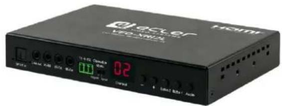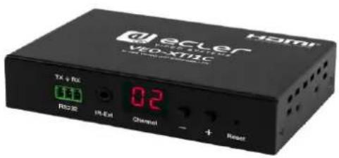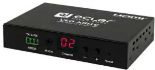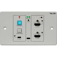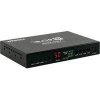
VEO-XTI2L - Audio/video converter Ecler - Free user manual and instructions
Find the device manual for free VEO-XTI2L Ecler in PDF.
| Product Type | IP audio/video extender, transmitter (VEO-XTI2L) and receiver (VEO-XRI2L) |
| Max Resolution | 3840x2160 at 30 Hz (input up to 3840x2160 at 60 Hz YUV 4:2:0) |
| HDCP Compatibility | HDCP 2.2 and HDCP 1.4 |
| Video Inputs | 1 x HDMI (transmitter) |
| Video Outputs | 1 x HDMI (receiver) |
| Audio Inputs | 1 x Line In (RCA) and 1 x S/PDIF (transmitter) |
| Audio Outputs | 1 x Line Out (RCA) and 1 x S/PDIF (receiver) |
| Network Connectivity | 1 x RJ45 (Cat.5e/6) Gigabit Ethernet with PoE, 1 x SFP for fiber optic |
| USB | 1 x USB Type B (transmitter), 1 x USB Type A (receiver), USB 2.0 over IP |
| IR | 2 x IR-RX (sensor), 1 x IR-TX (emitter), bidirectional wideband (38-56 kHz) |
| RS-232 | 1 x full-duplex port (Phoenix/Euroblock) |
| Power Supply | PoE (Power over Ethernet) or external 5V DC power adapter (included) |
| Transmission Distance | Up to 120 m over Cat.5e/6, up to 60 km over single-mode fiber optic |
| Main Features | 4K extension over IP, KVM (keyboard, mouse, video), video wall up to 8x8, unicast/multicast modes, control via EclerNet Manager, Web interface or TCP/IP commands |
| Maintenance and Cleaning | Clean with a dry cloth. Do not use water or liquid products. |
| Safety | Do not expose to rain or moisture. Unplug during storms. Use only specified accessories. |
| Spare Parts and Repairability | Have any repairs done by a qualified technician. Contact Ecler support for parts. |
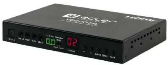
| General Information | Brand: Ecler, model: VEO-XTI2L (transmitter). Weight and dimensions not specified in the manual. |
Frequently Asked Questions - VEO-XTI2L Ecler
User questions about VEO-XTI2L Ecler
0 question about this device. Answer the ones you know or ask your own.
Ask a new question about this device
Download the instructions for your Audio/video converter in PDF format for free! Find your manual VEO-XTI2L - Ecler and take your electronic device back in hand. On this page are published all the documents necessary for the use of your device. VEO-XTI2L by Ecler.
USER MANUAL VEO-XTI2L Ecler
9 CONFIGURATION AVEC ECLERNET MANAGER....22
* How to configure a Cisco SG300 Ethernet Switch....68-80
20 HOW TO CONFIGURE A CISCO SG300 ETHERNET SWITCH INTRODUCTION 69
21 ESTABLISHING COMMUNICATION WITH THE CISCO ETHERNET SWITCH.....69
22 ENABLING IGMP PROTOCOL....70
23 ENABLING JUMBO FRAME....74
24 CONFIGURING THE DHCP SERVER 75
* How to configure D-Link DGS-1210 Ethernet Switch....79-85
25 HOW TO CONFIGURE D-LINK DGS-1210 ETHERNET SWITCH INTRODUCTION 80
26 ESTABLISHING COMMUNICATION WITH D-LINK ETHERNET SWITCH......80
27 ENABLING IGMP PROTOCOL....80
28 ENABLING Jumbo Frame....81
29 Disabling POWER Saving and EEE (Energy Efficient Ethernet) 82
30 CREATING VLANS FOR DANETM, VIDEO OVER IP AND CONTROL COEXISTENCE....83
1 REMARQUE IMPORTANTE

WARNING: SHOCK HAZARD - DO NOT OPEN
AVIS: RISQUE DE CHOC ÉLECTRIQUE - NE PAS OUVRIR

text_image
BML 6-1K BML Remote of the source Remote of the HDMI extendertext_image
Q/H Factory Reset Group Switchtext_image
d ecler VIDEO SYSTEMS Transmitter found. Connecting... Local IP: 192.168.1.16 Remote IP: 192.168.1.14 ID: VEO-ARIZLtext_image
Project Explorer (192.168.1.13 - Local) Devices (1 groups) All (0) Channels (1 groups) User Control Panels (0 Panels) Groups from All Members from Online and Unused Device List Add to Project Activate Device Finder Network Configuration... VEO-XRI2L 192.168.1.16 : 2210 VEO-XTI2L 192.168.1.14 : 2210 Network Configuration Device "VEO-XRI2L" Ethernet MAC 00-1A-96-FE-02-6A IP Address 192.168.1.16 UDP Port 2210 IP Subnet Mask 255.255.255.0 IP Gateway 192.168.1.1 OK Canceltext_image
Project Explorer (132.160.1.03 - Local) Groups from Device Container Devices All Channels All User Control Panels All Powered Device: VEO-84025 Members From Device Group : All Online and Unused Devices VEO-18025 VEO-800.54 / 2/19 VEO-XT25 (92.100.1.04 / 2/19) VEO-6705text_image
File Edit UCP Server View Help Explorer Design Deploy Project Explorer (192.168.1.13 - Local) Devices (1 groups) All (2) VEO-XTI2L VEO-XTI2L VEO-XRI2L VEO-XRI2L Channels (1 groups) User Control Panels (0 Panels) Online and Unused Device List D C U Ptext_image
File Edit UCP Server View Help Explorer Design Deploy Project Explorer (192.168.1.13 - Local) Devices (1 groups) All (2) VEO-XT12L VEO-XT12L VEO-XR12L VEO-XR12L Channels (1 groups) User Control Panels (0 Panels) Channel Listtext_image
Network Scan Upgrade Factors: Default Reduce Auto Device Info Version Hostname ID: Link Status MAC Address TC IP Hostname ID Testing Mode ● Multicast ○ Unicast Multicast IP: IP Mode ○ Auto IP ○ DHCP ○ Static IF Address: Subnet Mask: Default Gateways: FX IP Multicast IP OSI Video Wall Reset and Back Compensation(Unit: 0.1ms) OM: 0 OH: 0 VM: 0 VH: 0 Wall Size and Position Layout Vertical Monitor Count: 5 Horizontal Monitor Count: 5 0.0 0.1 0.2 0.3 0.4 1.0 1.1 1.2 1.3 1.4 2.0 2.1 2.2 2.3 2.4 3.0 3.1 3.2 3.3 3.4 4.0 4.1 4.2 4.3 4.4 Preference Stretch Type: FileIn Codebase Rotate: 9 Show OSOtext_image
Network Scan Upgrade Factory Default Reboot Apply Device Info Versions: Hostname ID: Lan Status: MAC Address TX IP Hostname ID Carting Node Multicast Unicast Multicast IP: IP Mode Auto IP DHCP Static IP Address: Subset Mask: Default Gateway: RV IP Multicast IP OSI Video Wall Beecl and Gap Compensation(Unit: 0.1mm) OW: 0 Opt: 0 WW: 0 VIT: 0 Wall Size and Position Layout Vertical Monitor Count: 2 Horizontal Monitor Count: 2 0_0 0_1 1_0 1_1 Preference Stretch Type: FitIn Clockwise Rate: 0 ✓ Shan OSDtext_image
System Video Wall Network Functions ► Version Information: ► Update Firmware: ► Utilities: ► Statistics: State Machine State: s_search Network ID (Host Name): 82CA8D853D73 IP Address: 169.254.6.167 Subnet Mask: 255.255.0.0 Default Gateway: 169.254.0.254 MAC Address: 82CA8D853D73 Casting Mode: Unicast Mode Link Status: on Link Mode: 1G Video Local Video Output: attached-n Video Timing Information: timing-[34] 640x480p@60Hz H- V- type=RGB HDCP=n (disable) color depth=0text_image
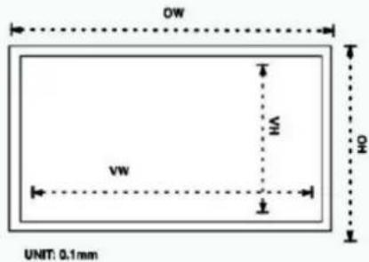
System Video Wall Network Functions Basic Setup: Bezel and Gap Compensation OW: 1 OH: 1 VW: 1 VH: 1 UNIT: 0.1mm Wall Size and Position Layout Vertical Monitor Count: 1 Horizontal Monitor Count: 1 Row Position: 0 Column Position: 0 Horizontal Monitor Count Vertical Monitor Count Horizontal Monitor Count Row Position: 0 UNID Panel Preferences Stretch Type: Fit In Clockwise Rotate: 0 Apply To: "This" device connected by your browser This Apply Show OSD Advanced Setup:Bezel and Gap Compensation
OW:

OH:

VW:

VH:


text_image
OW VW H UNIT: 0.1mmWall Size and Position Layout

text_image
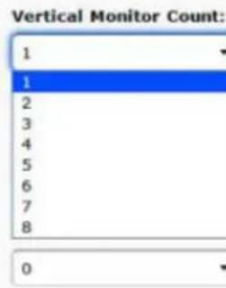
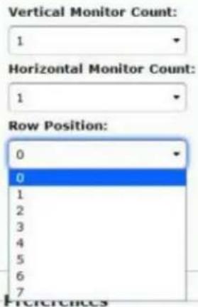
Vertical Monitor Count: 1 1 2 3 4 5 6 7 8 0
flowchart
graph TD
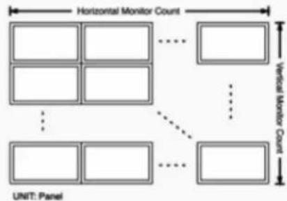
A["UNIT: Panel"] --> B["Unit"]
B --> C["Vertical Monitor Count"]
C --> D["Horizontal Monitor Count"]
D --> E["Grid Layout"]
style A fill:#f9f,stroke:#333
style B fill:#ccf,stroke:#333
style C fill:#cfc,stroke:#333
style D fill:#fcc,stroke:#333
style E fill:#ffc,stroke:#333
Wall Size and Position Layout
text_image
Vertical Monitor Count: 1 Horizontal Monitor Count: 1 Row Position: 0 0 1 2 3 4 5 6 7 References
flowchart
graph TD
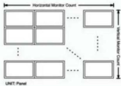
A["UNIT: Panel"] --> B["Horizontal Monitor Count"]
B --> C["Vertical Monitor Count"]
C --> D["Blank Box"]
C --> E["Blank Box"]
C --> F["Blank Box"]
C --> G["Blank Box"]
C --> H["Blank Box"]
style A fill:#f9f,stroke:#333
style B fill:#ccf,stroke:#333
style C fill:#cfc,stroke:#333
style D fill:#ffc,stroke:#333
style E fill:#ffc,stroke:#333
style F fill:#ffc,stroke:#333
style G fill:#ffc,stroke:#333
style H fill:#ffc,stroke:#333
text_image
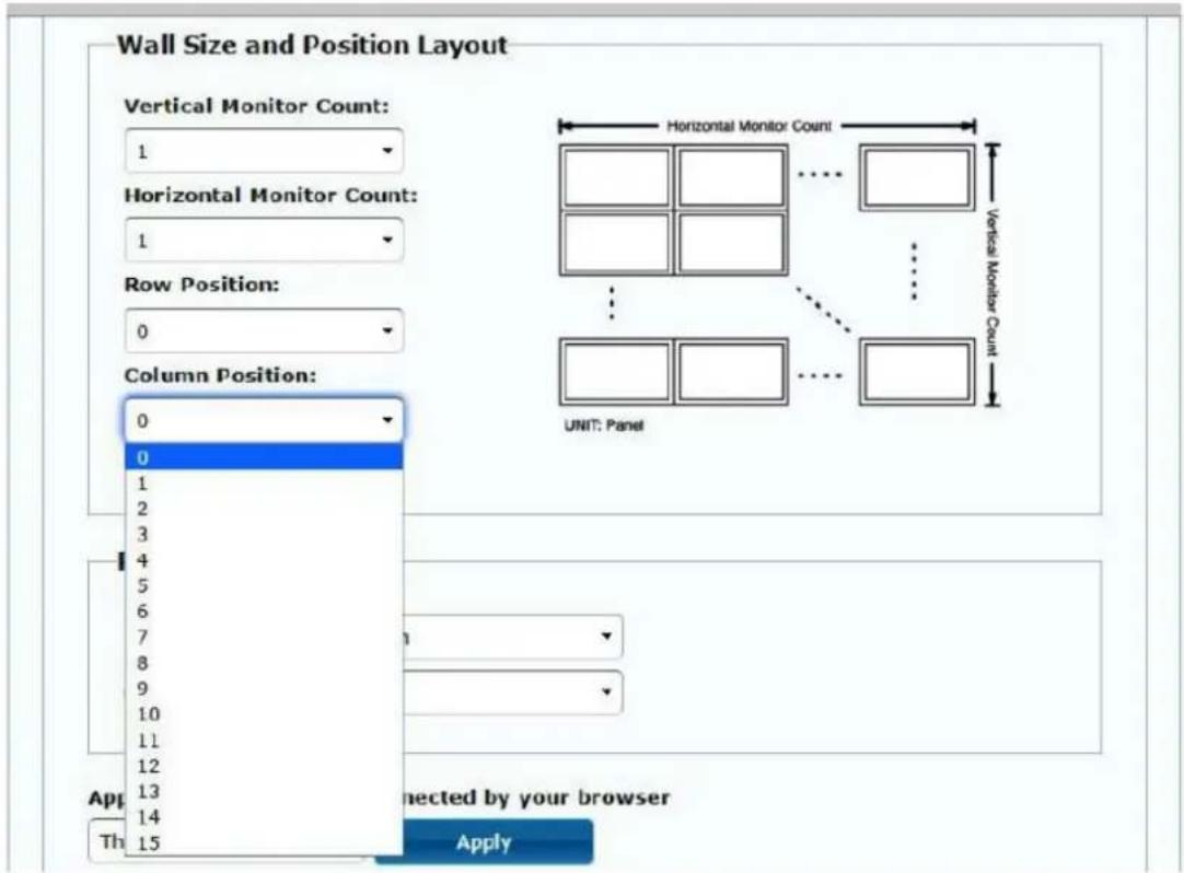
Wall Size and Position Layout Vertical Monitor Count: 1 Horizontal Monitor Count: 1 Row Position: 0 Column Position: 0 0 1 2 3 4 5 6 7 8 9 10 11 12 13 14 Th 15 UNIT: Panel Connected by your browser Applytext_image

Preferences Stretch Type: Fit In Clockwise Rotate: Stretch Out Preferences Stretch Type: Fit In Clockwise Rotate: 0 0 180 270 Apply To: "This" device connected by your browser This Apply11.2.5 Apply To (appliquer à)
text_image
Preferences Stretch Type: Fit In Clockwise Rotate: 0Apply To: "All" device(s) in the list

text_image
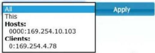
All This Hosts: 0000:169.254.10.103 Clients: 0:169.254.4.78 Applytext_image
Preferences Stretch Type: Fit In Clockwise Rotate: 0 Apply To: "This" device connected by your browser This Apply Show OSD Advanced Setup:11.2.6 Configuration avancée
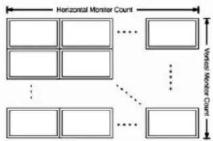
Wall Size and Position Layout
Vertical Monitor Count:

Horizontal Monitor Count:

Row Position:

Column Position:

flowchart
graph TD
A[" "] --> B[" "]
C[" "] --> D[" "]
E[" "] --> F[" "]
G[" "] --> H[" "]
I[" "] --> J[" "]
K[" "] --> L[" "]
M[" "] --> N[" "]
O[" "] --> P[" "]
Q[" "] --> R[" "]
S[" "] --> T[" "]
U[" "] --> V[" "]
W[" "] --> X[" "]
Y[" "] --> Z[" "]
AA[" "] --> AB[" "]
AC[" "] --> AD[" "]
AE[" "] --> AF[" "]
AG[" "] --> AH[" "]
AI[" "] --> AJ[" "]
AK[" "] --> AL[" "]
AM[" "] --> AN[" "]
AO[" "] --> AP[" "]
AQ[" "] --> AR[" "]
AS[" "] --> AT[" "]
AU[" "] --> AV[" "]
AW[" "] --> AX[" "]
AY[" "] --> AZ[" "]
BA[" "] --> BB[" "]
BC[" "] --> BD[" "]
BE[" "] --> BF[" "]
BG[" "] --> BH[" "]
BI[" "] --> BJ[" "]
BK[" "] --> BL[" "]
BM[" "] --> BN[" "]
BO[" "] --> BP[" "]
BQ[" "] --> BR[" "]
BS[" "] --> BT[" "]
BU[" "] --> BV[" "]
BW[" "] --> BX[" "]
BY[" "] --> BZ[" "]
CA[" "] --> CB[" "]
CC[" "] --> CD[" "]
CE[" "] --> CF[" "]
CG[" "] --> DH[" "]
DI[" "] --> DJ[" "]
DK[" "] --> DL[" "]
DM[" "] --> DJ
DB[" "] --> DC[" "]
DD[" "] --> DV[" "]
DX[" "] --> DW[" "]
DXB[" "] --> DXD[" "]
DXC[" "] --> DXC
DXD[" "] --> DXD
DXC --> DXC
DXD --> DXC
DXC --> DXC
DXC --> DXC
DXC --> DXC
DXC --> DXC
DXC --> DXC
DXC --> DXC
DXC --> DXC
DXC --> DXC
DXC --> DXC
DXC --> DXC
DXC --> DXC
DXC --> DXC
DXC --> DXC
DXC --> DXC
DXC --> DW
DXC --> BX
DXC --> BY
DXC --> Z
DXC --> DA
DXC --> DB
DXC --> DC
DXC --> DW
DXC --> BX
DXC --> BY
DXC --> Z
DXC --> DA
DXC --> DB
DXC --> Z
DXC --> DA
DXC --> DB
DXC --> Z
DXC --> DA
DXC --> DB
DXC --> Z
DXC --> DA
DXC --> DB
DXC --> Z
DXC --> DA
DXC --> DB
DXC --> Z
DXC --> DA
DXC --> DB
DXC --> Z
DXA[" "] <--> B
DXB[" "] <--> C
DXC[" "] <--> D
DXD[" "] <--> E
DXE[" "] <--> F
DXF[" "] <--> G
DXG[" "] <--> H
DXH[" "] <--> I
DXI[" "] <--> J
DXJ[" "] <--> K
DXK[" "] <--> L
DXL[" "] <--> M
DXM[" "] <--> N
DXN[" "] <--> O
DXO[" "] <--> P
DXP[" "] <--> Q
DXQ[" "] <--> R
DXR[" "] <--> S
DXS[" "] <--> T
DXT[" "] <--> U
DXU[" "] <--> V
DXV[" "] <--> W
DXW[" "] <--> X
DXX[" "] <--> Y
DXY[" "] <--> Z
UNIT: Panel
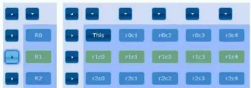
Step 1: Choose Control Target
text_image
R0 R1 R2 This r0c1 r0c2 r0c3 r0c4 r1c0 r1c1 r1c2 r1c3 r1c4 r2c0 r2c1 r2c2 r2c3 r2c4Show OSD
Reset to Basic Setup:

natural_image
Two side-by-side images showing a purple and green spherical object with white curved base, no text or symbols present.natural_image
3D rendered molecular model with purple and green spheres, shown in two different angles (no text or symbols)natural_image
Close-up of a purple, glossy sphere with green and white accents (no text or symbols visible)natural_image
Close-up of a purple and green spherical object with a white curved handle, no text or symbols visibletext_image
System Video Wall Network Functions IP Setup IP Mode: Auto IP DHCP Static IP Address: 169.254.6.167 Subnet Mask: 255.255.0.0 Default Gateway: 169.254.0.254 Apply Casting Mode Multicast Unicast Auto select USB operation mode per casting mode (recommended) Apply11.3.1 Auto IP
text_image
IP Setup IP Mode: Auto IP DHCP Static IP Address: 169.254.6.167 Subnet Mask: 255.255.0.0 Default Gateway: 169.254.0.254 Applytext_image
IP Setup IP Mode: Auto IP DHCP Static IP Address: (From DHCP Server) Subnet Mask: (From DHCP Server) Default Gateway: (From DHCP Server) Applytext_image
IP Setup IP Mode: Auto IP DHCP Static IP Address: 192.168.0.50 Subnet Mask: 255.255.255.0 Default Gateway: 192.168.0.1 Apply11.3.4 Casting Mode (mode de diffusion)
text_image
Casting Mode Multicast Unicast Auto select USB operation mode per casting mode (recommended) Applytext_image
Video over IP Enable Video over IP Enable Video Null Copy EBIT from this Video Output (Default disabled under modification mode) Order Output Mode: False Through Timeout for Detecting Video Lost: 10 seconds Turn off screen on video lost Apply USB over IP Enable USB over IP Operation Mode: Auto-select mode (Recommended, choose per network carding mode) Active on Link (access network's default mode) Active per request (Efficient network's default mode) Compatibility Mode: SVM over IP (Network other means [keyphone]/week parent not working on expected) Applytext_image
Timeout for Detecting Video Lost: 10 seconds Turn off screen on video lost Applytext_image
Timeout for Detecting Video Lost: 10 seconds Turn off screen on video lost 3 seconds 5 seconds ✓ 10 seconds 20 seconds 30 seconds 60 seconds Never Timeouttext_image
ecler VIDEO SYSTEMS Trying to find the transmitter... P#: v2.00r1 Local IP: 192.168.3.16 Remote IP: Unknown ID: BLUAYtext_image
3 seconds 5 seconds ✓ 10 seconds 20 seconds 30 seconds 60 seconds Never Timeout Timeout for Detecting Video Lost Turn off screen on video lost Applytext_image
USB over IP ✓ Enable USB over IP Operation Mode: ● Auto select mode (Recommended, choose per network casting mode) ○ Active on link (Unicast network's default mode) ○ Active per request (Multicast network's default mode) Compatibility Mode: ✓ K/M over IP (Uncheck when mouse/keyboard/touch panel not working as expected) ApplyEnable Serial over IP
Operation Mode:
◎ Type 1 (Need extra control instruction. For advanced usage.)
Type 2 (Recommended, Dumb redirection.)
Type 1 guest mode
Type 2 guest mode
Baudrate Setting for Type 2:
Baudrate: 115200
Data bits: 8
Parity: None
Stop bits: 1
Apply
12 CONNEXION PAR FIBRE OPTIQUE
converted to 3840X2160@30Hz,
1080P/1080i/720P/576P/576i/480P/480i
Video connectors HDMI 1.4 with thread lock
HDCP 2.2 Compliant
Network requirements Accordance with IGMP and Jumbo Frames
Network transmission bit rate Up to 300Mbps
Video latency 1 to 3 frames depending on network conditions
Network connectors RJ45 with LED indication and SFP receptacle
Default IP Auto IP (239.254.x.y)
PoE power operation 802.3af
Transmission distance Up to 120m. (via CATx) in point-to-point topology;
Up to 100m when connected to standard Ethernet
devices; Up to 60Km via single mode fiber; Up to
2Km via multimode fiber;
Audio formats LPCM 2.0, Dolby True HD, DTS-HD Master audio
Sampling rate 192 kHz
Bit depth 24-bit
Analog audio connectors 3.5mm stereo minijack
Digital audio connectors S/PDIF Toslink
IR bandwidth supported 38 -56 KHz
USB ports TX: USB 2.0 Keyboard / Mouse 1 x USB type B
RX: USB 2.0 Keyboard / Mouse 2 x USB type A
RS-232 Connector 3 pins Phoenix
Operating temperature 0^ C - 50^ C / 32^ F - 122^ F
Humidity 5 - 90% RH (non-condensing)
Energy consumption 3 W MAX (TX y RX)
Input supply AC100\~240V 50/60Hz Output: DC 5V/1A
Dimensions A x A x P 26mm x 170mm x 109mm (1.02" x 6.69" x 4.29")
(TX y RX)
Weight 470g (1,036 lbs.)
VEO-XTI2L / VEO-XRI2L
CONTRÔLE PAR TCP / IP
text_image
Dell XR VSSX-X728 0.2 Channel Signal Set1 Act1 Display A Control Display B Display C Display D Display E Display F Display G Display H Display I Display J Display K Display L Display M Display N Display O Display P Display Q Display R Display S Display T Display U Display V Display W Display X Display Y Display Z Display A Display B Display C Display D Display E Display F Display G Display H Display I Display J Display K Display L Display M Display N Display O Display P Display Q Display R Display S Display T Display U Display V Display W Display X Display Y Display Z
text_image
WECER VCC-XH2L T4+92 Generation 0.2 Signal Channel 8bit/2 MHz AudioMANUEL DE CONTRÔLE PAR TCP / IP
15 PROTOCOLE DE CONTRÔLE PAR UNE TIERCE PARTIE : CONNEXION ET IDENTIFICATION
UDP Setup | Serial | TCP Client | TCP Server | UDP | Test Mode | About |
Received/Sent data
Connecting to 169.254.8.137 ...
Connected to 169.254.8.137
NVT: FF FD 01
NVT: FF FD 1F
NVT: FF FD 21
NVT: FF FB 01
NVT: FF FD 01
NVT: FF FB 03
{OD}{OD}{OA}ast3-client82AC6B76B590 login: root
- echo 0 > /sys/devices/platform/display/screen_off
- echo 1 > /sys/devices/platform/display/screen_off
- e e_vw_enable_1_1_0_0
| e e_reconnect::0002 e e_vw_enable_0_0_0_0 0_1 | |
- e e_vw_enable_0_0_0_0
text_image
Serial over IP Enable Serial over IP Operation Mode: Type 1 (Need extra control instruction. For advanced usage.) Type 2 (Recommended, Dumb redirection.) Type 1 guest mode Type 2 guest mode Baudrate Setting for Type 2: Baudrate: 115200 Data bits: 8 Parity: None Stop bits: 1 ApplyHow to configure a Cisco SG300 Ethernet Switch for Ecler VEO over IP products
text_image
eSCEC VCC-STYLE HDMI I/O port I/O port I/O port I/O port I/O port I/O port I/O port I/O port I/O port I/O port I/O port I/O port I/O port I/O port I/O port I/O port I/O port I/O port I/O port I/O port I/O port I/O port I/O port I/O port I/O port I/O ports I/O ports I/O ports I/O ports I/O ports I/O ports I/O ports I/O ports I/O ports I/O ports I/O ports I/O ports I/O ports I/O ports I/O ports I/O ports I/O ports I/O ports I/O ports I/O ports I/O ports I/O ports I/O ports I/O ports I/O ports I/O port I/O port I/O port I/O port I/O port I/O port I/O port I/O port I/O port I/O port I/O port I/O port I/O port I/O port I/O port I/O port I/O port I/O port I/O port I/O port I/O port I/O port I/O port I/O port I/O Portugal
text_image
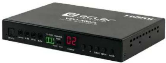
d'ecler V80-XR1X HDMI 12.4-65 Options 0.2 Control LED/USB Audio
text_image
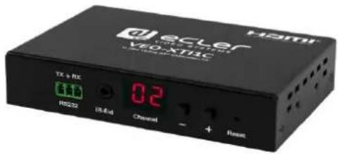
d i e c t e r VEO-XTRC TX + NE HS232 IS/IE4 0.2 Channel + Reset
text_image
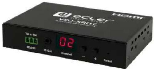
d'echer VEO2-RHC TX + RX RS233 02 IR-Ext Channel + ResetQUICK START GUIDE
20 HOW TO CONFIGURE A CISCO SG300 ETHERNET SWITCH INTRODUCTION
Due to the network requirements established by Audinate® for Dante™ Networks and taking in consideration the network requirements for our VEO over IP devices, this quick guide aims to explain how to configure the Cisco SG300 family of switches in order to make them compliant to these requirements. All the requirements are mandatory for every switch used in a Dante or VEO over IP system, independently by the brands.
21 ESTABLISHING COMMUNICATION WITH THE CISCO ETHERNET SWITCH
- Connect your computer to the Cisco Ethernet Switch using an Ethernet cable. The Cisco SG300 Ethernet Switch comes with a default Static IP address of 192.168.1.254; you must configure your PC with a Static IP address in the same subnet.
- Set a Static IP address on your computer network interface card, such as 192.168.1.66 along with the following mask 255.255.255.0.
- Open your Internet browser and digit the default IP address of the switch: http://192.168.1.254. The Default User ID and Password for the unit is "Cisco".
22 ENABLING IGMP PROTOCOL
The IGMP Protocol is mandatory for the correct operation of the VEO over IP products in multicast configurations. Without IGMP the audio/video can't work properly or may freeze.
- Select Multicast → Properties. Enable the Bridge Multicast Filtering Status by activating the related selection box and clicking on Apply.
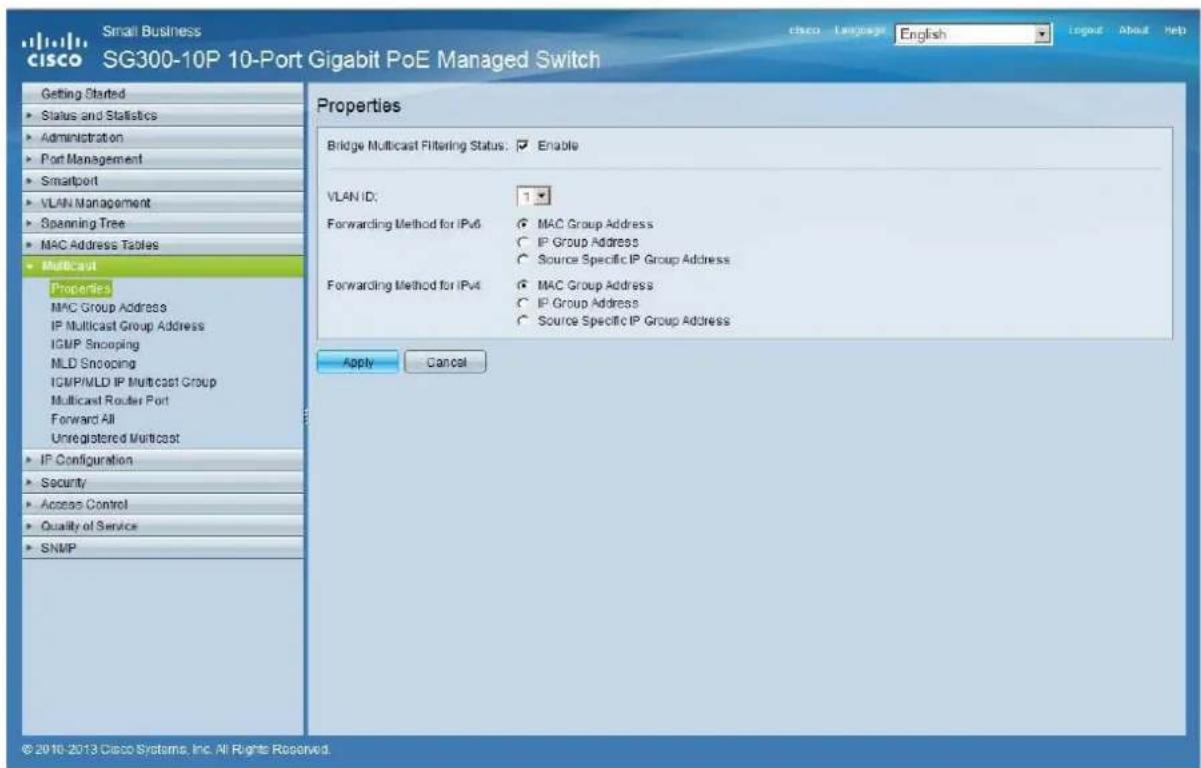
text_image
Small Business cisco SG300-10P 10-Port Gigabit PoE Managed Switch Getting Started Status and Statistics Administration Port Management Smartport VLAN Management Spanning Tree MAC Address Tables Multicast Properties MAC Group Address IP Multicast Group Address IGMP Snooping MLD Snooping IGMP/MLD IP Multicast Group Multicast Router Port Forward All Unregistered Multicast IP Configuration Security Access Control Quality of Service SNMP Properties Bridge Multicast Filtering Status: Enable VLAN ID: 1 Forwarding Method for IPv6 MAC Group Address IP Group Address Source Specific IP Group Address Forwarding Method for IPv4 MAC Group Address IP Group Address Source Specific IP Group Address Apply Cancel © 2010-2013 Cisco Systems, Inc. All Rights Reserved.- Select Multicast → IGMP Snooping. Enable the IGMP Snooping Status by activating the related selection box and clicking on Apply.
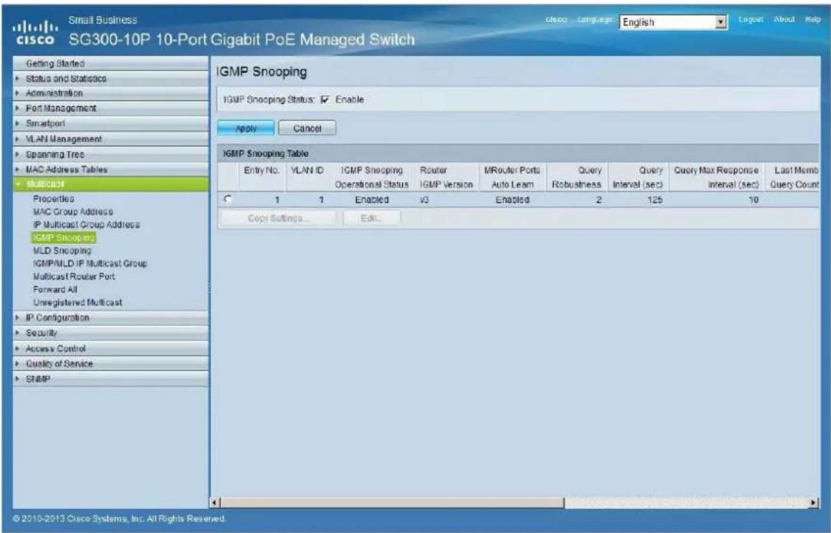
text_image
Small Business cisco SG300-10P 10-Port Gigabit PoE Managed Switch Getting Started Status and Statistics Administration Port Management Smartport VLAN Management Spanning Tree MAC Address Tables Multicast Properties MAC Group Address IP Multicast Group Address GMP Snooping MLD Snooping IGMP/MLD IP Multicast Group Multicast Router Port Forward All Unregistered Multicast IP Configuration Security Access Control Quality of Service SNMP IGMP Snooping Status: ✓ Enable. Apply Cancel IGMP Snooping Table Entry No.VLAN ID IGMP Snooping Operational Status Router IGMP Version MRouter Port Auto Learn Query Robustness Query Interval (sec) Query Max Response Interval (sec) Last Month Query Count 1 1 Enabled v3 Enabled 2 125 10 Copy Settings... Edit... © 2010-2013 Cisco Systems, Inc. All Rights Reserved.- In the IGMP Snooping Table, select the default VLAN ID 1 and click on Edit.
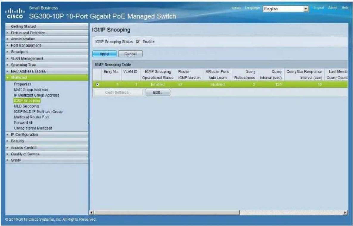
text_image
Small Business cisco SG300-10P 10-Port Gigabit PoE Managed Switch Getting Started Status and Statistics Administration Port Management Smartport VLAN Management Spanning Tree MAC Address Tables Multicast Properties MAC Group Address IP Multicast Group Address IGMP Snooping MLD Snooping IGMP/MLD IP Multicast Group Multicast Router Port Forward All Unregistered Multicast IP Configuration Security Access Control Quality of Service SNMP IGMP Snooping Status Enable Apply Cancel IGMP Snooping Table Entry No. VLAN ID IGMP Snooping Router MRouter Ports Query Robustness Query Interval (sec) Query Max Response Interval (sec) Last Memb Query Count 1 1 Enabled √3 Enabled 2 125 10 Copy Settings Edit... © 2010-2013 Cisco Systems, Inc. All Rights Reserved.- In the resulting window, activate the related selection box for IGMP Snooping Status and verify that the Immediate Leave selection box is enabled and then click on Apply.
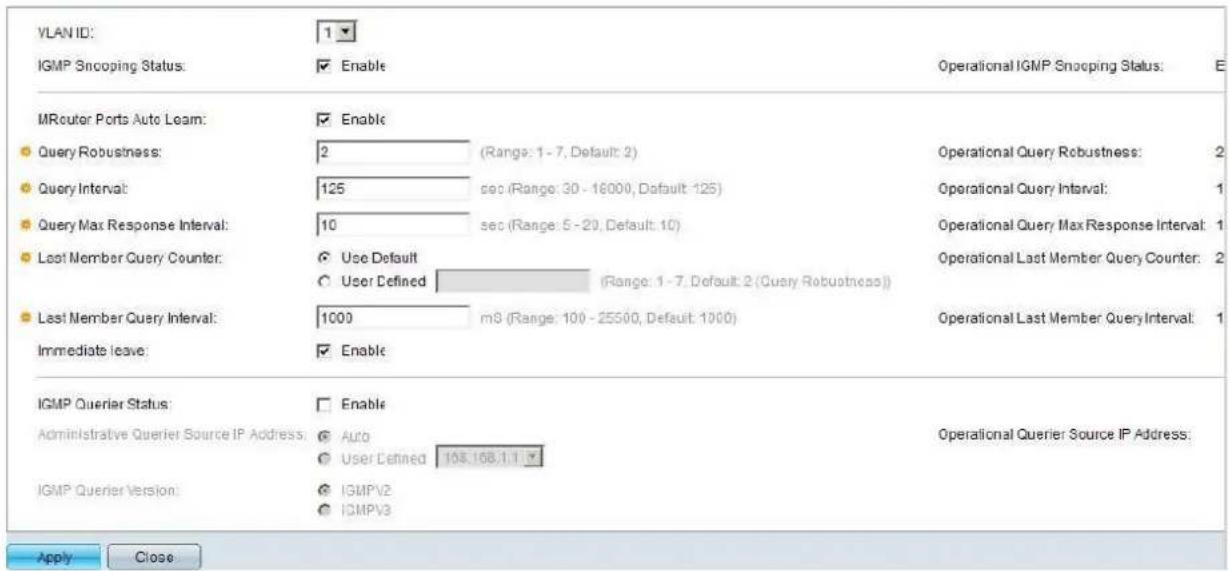
text_image
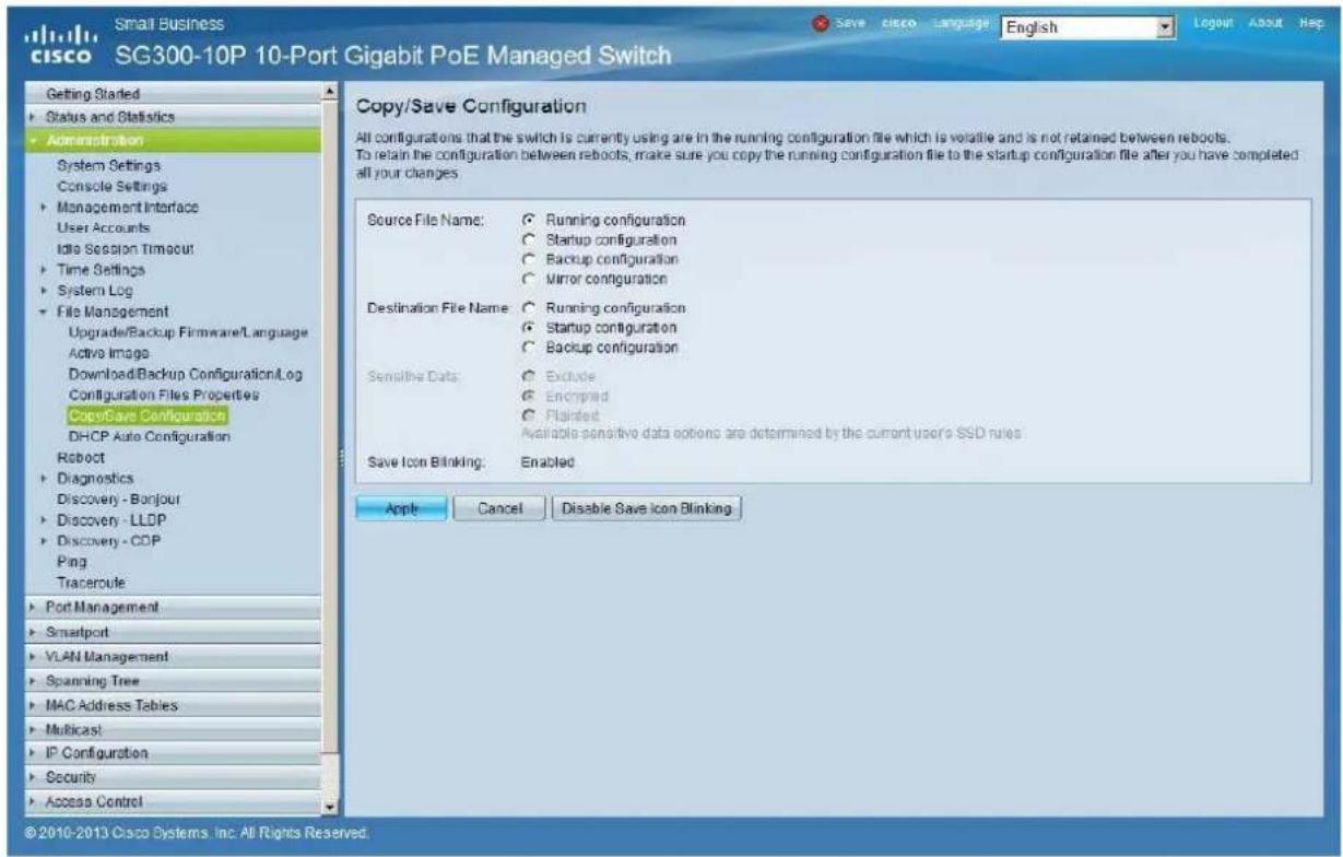
VLAN ID: 1 IGMP Snooping Status: Enable Operational IGMP Snooping Status: E MRouter Ports Auto Learn: Enable Query Robustness: 2 (Range: 1 - 7, Default: 2) Operational Query Robustness: 2 Query Interval: 125 sec (Range: 30 - 18000, Default: 125) Operational Query Interval: 1 Query Max Response Interval: 10 sec (Range: 5 - 20, Default: 10) Operational Query Max Response Interval: 1 Last Member Query Counter: Use Default (Range: 1 - 7, Default: 2 (Query Robustness)) User Defined (Range: 1 - 7, Default: 2 (Query Robustness)) Last Member Query Interval: 1000 m3 (Range: 100 - 25500, Default: 1000) Operational Last Member Query Interval: 1 Immediate leave: Enable IGMP Querier Status: Enable Administrative Querier Source IP Address: Auto Operational Querier Source IP Address: User Defined 103.168.1.1 IGMP Querier Version: IGMPV2 IGMPV3 Apply Close- Select Administration → File Management → Copy/Save Configuration. Enable Running Configuration and Startup Configuration as shown below and save all changes by clicking Apply.
text_image
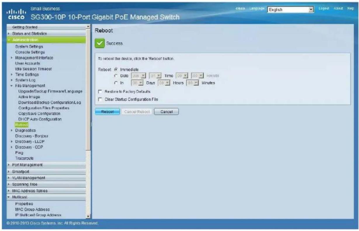
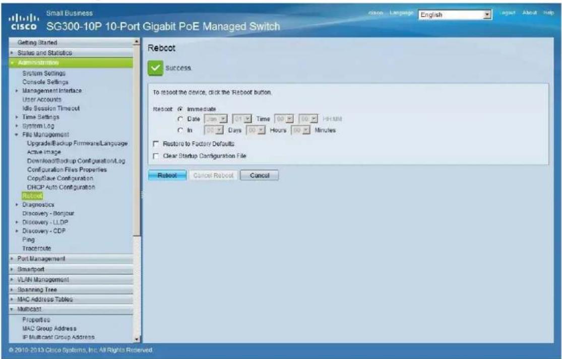
Small Business cisco SG300-10P 10-Port Gigabit PoE Managed Switch Getting Started Status and Statistics Administration System Settings Console Settings Management Interface User Accounts Idle Session Timeout Time Settings System Log File Management Upgrade/Backup Firmware/Language Active Image Download/Backup Configuration.Log Configuration Files Properties Copy/Save Configuration DHCP Auto Configuration Roboct Diagnostics Discovery - Bonjour Discovery - LLDP Discovery - CDP Ping Tracercute Port Management Smartport VLAN Management Spanning Tree MAC Address Tables Multicast IP Configuration Security Access Control Copy/Save Configuration All configurations that the switch is currently using are in the running configuration file which is volatile and is not retained between reboots. To retain the configuration between reboots, make sure you copy the running configuration file to the startup configuration file after you have completed all your changes. Source File Name: Running configuration Startup configuration Backup configuration Mirror configuration Destination File Name: Running configuration Startup configuration Backup configuration Sensitive Data: Exclude Encrypted Plaintest Available sensitive data options are determined by the current user's SSD rules. Save Icon Blinking: Enabled Apple Cancel Disable Save Icon Blinking © 2010-2013 Cisco Systems, Inc. All Rights Reserved.- Select Administration → File Management → Reboot, and click on the Reboot button to reboot the Ethernet switch and make all the changes running.
text_image
Small Business SG300-10P 10-Port Gigabit PoE Managed Switch Getting Started Status and Statistics Administration System Settings Console Settings Management Interface User Accounts Idle Session Timeout Time Settings System Log File Management Upgrade/Backup Firmware/Language Active Image Download/Backup Configuration/Log Configuration Files Properties Copy/Save Configuration DHCP Auto Configuration Reboot Diagnostics Discovery - Bonjour Discovery - LLDP Discovery - CDP Ping Tracercute Port Management Smartport VLAN Management Scanning Tree MAC Address Tables Multicast Properties MAC Group Address IP Multicast Group Address Reboot Language English Logout About Help Success To reboot the device, click the 'Reboot button. Reboot: Immediate Date 00 Time 00 HHMM In 00 Days 00 Hours 00 Minutes Restore to Factory Defaults Clear Startup Configuration File Reboot Cancel Reboot Cancel © 2010-2013 Cisco Systems, Inc. All Rights Reserved.23 ENABLING JUMBO FRAME
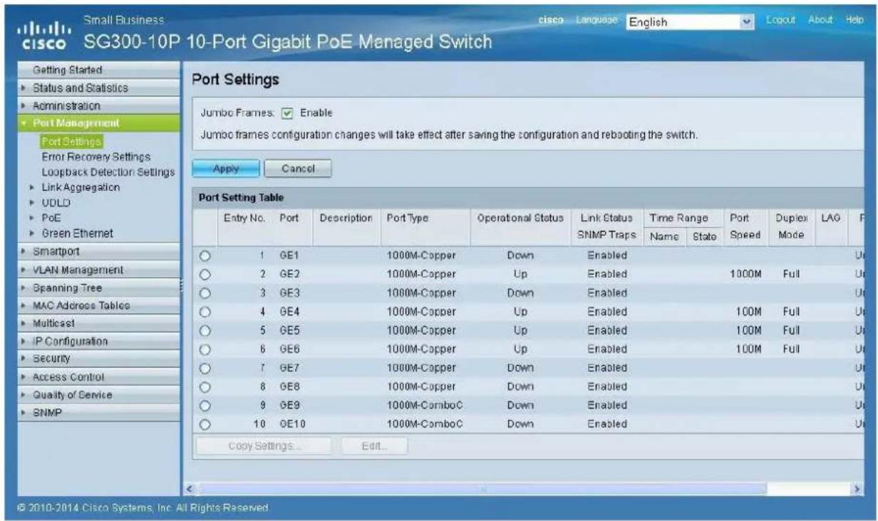
- Select Port Management → Port Settings. Enable Jumbo Frames by activating the related selection box and click on Apply.
text_image
Small Business cisco SG300-10P 10-Port Gigabit PoE Managed Switch Getting Started Status and Statistics Administration Port Management Port Settings Error Recovery Settings Loopback Detection Settings Link Aggregation UDLD PoE Green Ethernet Smartport VLAN Management Spanning Tree MAC Address Tables Multicost IP Configuration Security Access Control Quality of Service SNMP Port Settings Jumbo Frames. Enable Jumbo frames configuration changes will take effect after saving the configuration and rebooting the switch. Apply Cancel Port Setting Table Entry No. Port Description Port Type Operational Status Link Status Time Range Port Speed Duplex LAG F SNMP Traps Name State Mode 1 GE1 1000M-Copper Down Enabled 2 GE2 1000M-Copper Up Enabled 1000M Full 3 GE3 1000M-Copper Down Enabled 4 GE4 1000M-Copper Up Enabled 100M Full 5 GE5 1000M-Copper Up Enabled 100M Full 6 GE6 1000M-Copper Up Enabled 100M Full 7 GE7 1000M-Copper Down Enabled 8 GE8 1000M-Copper Down Enabled 9 GE9 1000M-ComboC Down Enabled 10 GE10 1000M-ComboC Down Enabled Copy Settings... Edit... © 2010-2014 Cisco Systems Inc. All Rights Reserved24 CONFIGURING THE DHCP SERVER
The DHCP Server will automatically configure the IP addresses of each device connected to the switch. All the devices need to be set as DHCP client in their own Network Configuration page. This allows avoiding any conflict between devices.
Note: Please check VEO user manual for IP configurations of each product, accordingly to your installation needs.
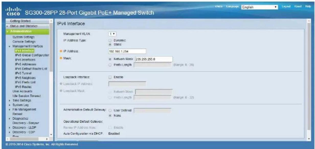
- To change the Ethernet Switch Static IP address to the same subnet as the AV over IP Devices, select Administration → Management Interface → IPv4 Interface. Set IP Address Type to Static, and enter the IP Address (accordingly to your network requirements), and set the Network Mask to 255.255.255.0. In this case we e default IP address. After applying these settings you need to change the IP address on your computer network interface card to the same subnet just set above.
text_image
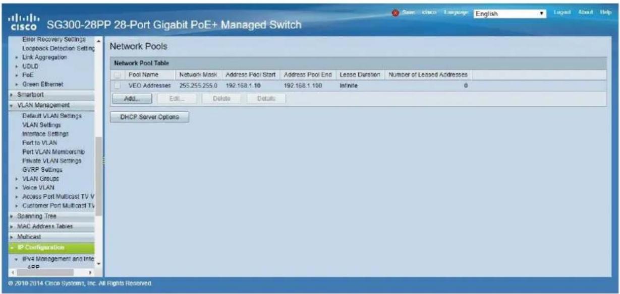
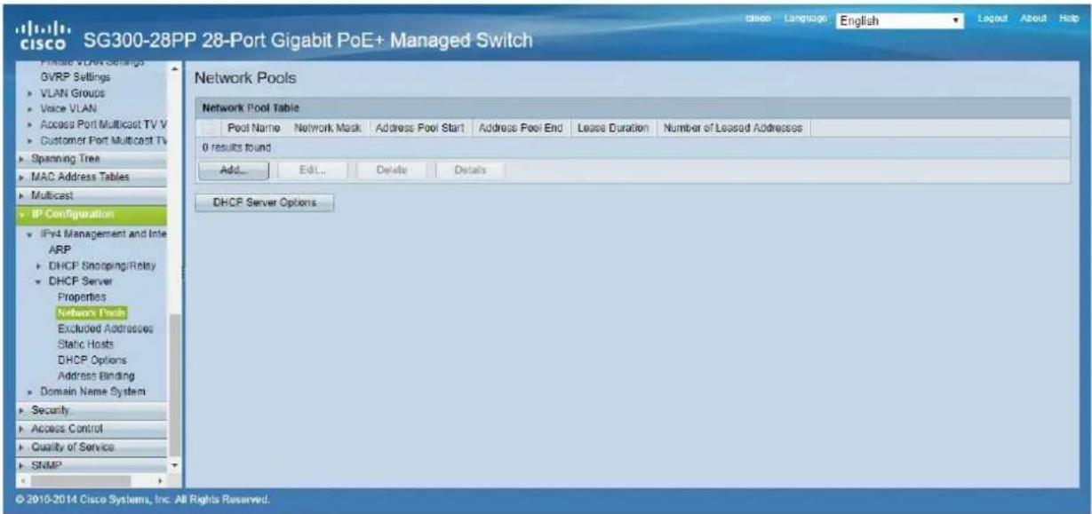
cisco SG300-28PP 28-Port Gigabit PoE+ Managed Switch Getting Started Status and Statistics Administration System Settings Console Settings Management Interface IPv4 Interface IPv6 Global Configuration IPv6 Interfaces IPv6 Addresses IPv6 Default Router List IPv6 Tunnel IPv6 Neighbors IPv6 Prefix List IPv6 Routes User Accounts Idle Session Timeout Time Settings System Log File Management Reboot Diagnostics Discovery - Bonjour Discovery - LLDP Discovery - CDP Pina IPv4 Interface Management VLAN: 1 IP Address Type: Dynamic Static IP Address: 192.166.1.254 Mask: Network Mask: 255.255.255.0 Prefix Length (Range 8 - 30) Loopback Interface: Enable Loopback IP Address: Loopback Mask: Network Mask: Prefix Length (Range 8 - 32) Administrative Default Gateway: User Defined None Operational Default Gateway: Remove IP Address Now: Enable Auto Configuration via DHCP: Enabled © 2010-2014 Cisco Systems, Inc. All Rights Reserved.- Select IP Configuration → DHCP Server → Network Pools and click on the Add... button
text_image
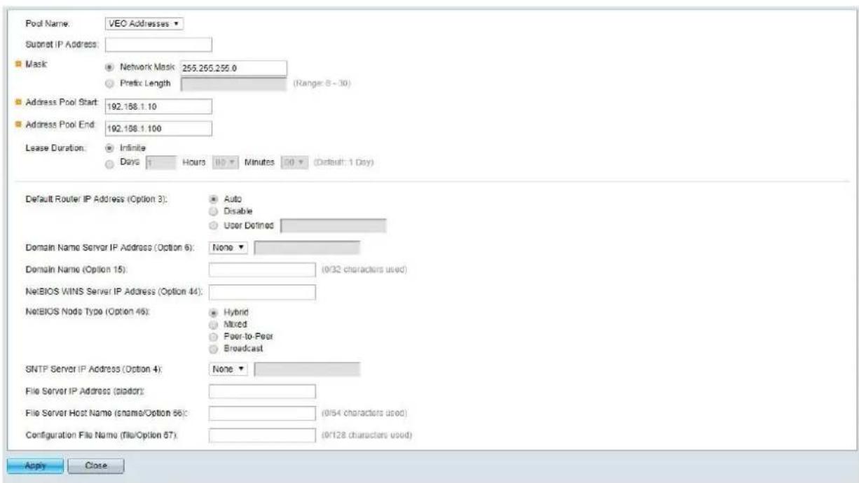
cisco SG300-28PP 28-Port Gigabit PoE+ Managed Switch Private VCR Settings GVRP Settings VLAN Groups Voice VLAN Access Port Multicast TV V Customer Port Multicast TV Spanning Tree MAC Address Tables Multicast IP Configuration IPv4 Management and Inter ARP DHCP Shopping/Relay DHCP Server Properties Network Pools Excluded Addresses Static Hosts DHCP Options Address Binding Domain Name System Security Access Control Quality of Service SNMP Network Pools Network Pool Table Pool Name Network Mask Address Pool Start Address Pool End Lease Duration Number of Leased Addresses 0 results found Add... Edit... Delete Details DHCP Server Options © 2010-2014 Cisco Systems, Inc. All Rights Reserved.- Set the Pool Name, the Network Mask (255.255.255.0), the Address Pool Start (192.168.1.10), and the Address Pool End (192.168.1.100). Verify that you allocate enough IP addresses for all Transmitters and Receivers present on the network.
text_image
Pool Name: VEO Addresses Submit IP Address: Mask Network Mask 255.265.255.0 (Range: 8 - 30) Address Pool Start: 192.158.1.10 Address Pool End: 192.158.1.100 Lease Duration: Infinite Days 1 Hours 10 Minutes 20 (Default: 1 Day) Default Router IP Address (Option 3): Auto Disable User Defined Domain Name Server IP Address (Option 6): None Domain Name (Option 15): (9/32 characters used) NetBIOS WINS Server IP Address (Option 44): NetBIOS Node Type (Option 45): Hybrid Mixed Peer-to-Peer Broadcast SNTP Server IP Address (Option 4): None File Server IP Address (Sladder): File Server Host Name (snames/Option 56): (9/54 characters used) Configuration File Name (file/Option 57): (9/128 characters used) Apply CloseClick on the Apply button.

text_image
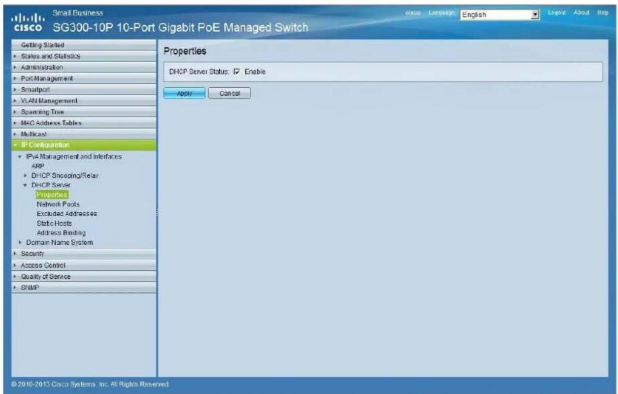
cisco SG300-28PP 28-Port Gigabit PoE+ Managed Switch Error Recovery Settings Loopback Detection Settings Link Aggregation UDLD PoE Green Ethernet Smartport VLAN Management Default VLAN Settings VLAN Settings Interface Settings Port to VLAN Port VLAN Membership Private VLAN Settings GVRP Settings VLAN Groups Voice VLAN Access Port Multicast TV V Customer Port Multicast TV Spanning Tree MAC Address Tables Multicast IP Configuration IPV4 Management and Inte APP Network Pools Network Pool Table Pool Name Network Mask Address Pool Start Address Pool End Lease Duration Number of Leased Addresses VEO Addresses 255.255.255.0 192.168.1.10 192.168.1.100 Infinite 0 Add Edit Delete Details DHCP Server Options © 2010-2014 Cisco Systems, Inc. All Rights Reserved.- Select IP Configuration → IPv4 Management and Interfaces → DHCP Server → Properties.
Enable the DHCP Server Status by activating the related selection box and clicking on Apply.
text_image
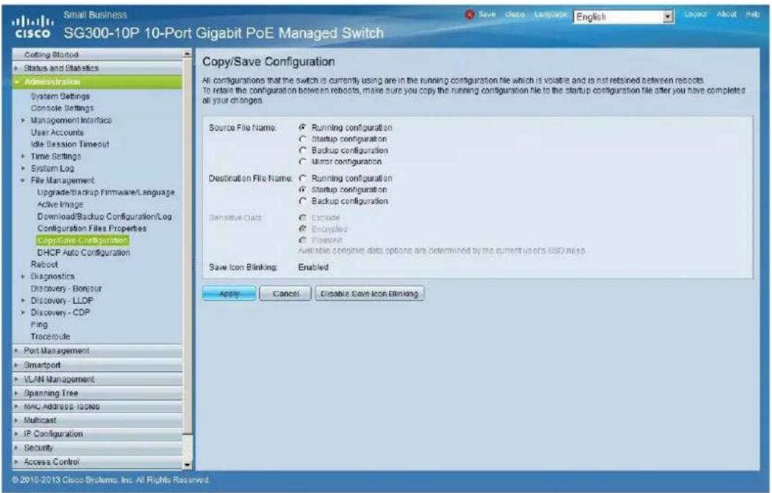
Small Business cisco SG300-10P 10-Port Gigabit PoE Managed Switch Getting Started Status and Statistics Administration Port Management Smartport VLAN Management Spanning Tree MAC Address Tables Multicast IP Configuration IPv4 Management and Interfaces ARP DHCP Shopping/Relay DHCP Server Properties Network Pools Excluded Addresses Static Hosts Address Binding Domain Name System Security Access Control Quality of Service SNMP Properties DHCP Server Status: ☑ Enable Apply Cancel © 2010-2013 Cisco Systems, Inc. All Rights Reserved- Select Administration → File Management → Copy/Save Configuration. Enable Running Configuration and Startup Configuration as shown below and save all changes by clicking Apply.
text_image
Small Business cisco SG300-10P 10-Port Gigabit PoE Managed Switch Editing Started Status and Statistics Administration System Settings Console Settings Management Interface User Accounts Idle Session Timeout Time Settings System Log File Management Upgrade/Backup Firmware/Language Active Image Download/Backup Configuration/Log Configuration Files Properties CopySave Configuration DHCP Auto Configuration Reboot Diagnostics Discovery - Bonjour Discovery - LLDP Discovery - CDP Ping Trecetroute Port Management Smartport VLAN Management Spanning Tree MAC Address IDs Multicast IP Configuration Security Access Control Copy/Save Configuration All configurations that the switch is currently using are in the running configuration file which is volatile and is not retained between reboots. To retain the configuration between reboots, make sure you copy the running configuration file to the startup configuration file after you have completed all your changes. Source File Name: Running configuration Startup configuration Backup configuration Mirror configuration Destination File Name: Running configuration Startup configuration Backup configuration Sensitive Data: Exclude Excepted Present Available sensitive data options are determined by the current uses of SSD rules Save Icon Blinking Enabled Apply Cancel Disable Save Icon Blinking © 2010-2013 Cisco Systems, Inc. All Rights Reserved.- Select Administration → File Management → Reboot, and click on the Reboot button to reboot the Ethernet switch and make all the changes running.
text_image
Small Business cisco SG300-10P 10-Port Gigabit PoE Managed Switch Getting Started Status and Statistics Administration System Settings Console Settings Management Interface User Accounts Idle Session Timeout Time Settings System Log File Management Upgrade/Backup Firmware/Language Active Image Download/Backup Configuration\Log Configuration Files Properties Copy/Save Configuration DHCP Auto Configuration Reboot Diagnostics Discovery - Bonjour Discovery - LDDP Discovery - CDP Ping TraceRoute Port Management Smartport VLAN Management Spanning Tree MAC Address Tables Multicast Properties MAC Group Address IP Multicast Group Address Reboot Success To reboot the device, click the Reboot button. Reboot Immediate Date Jan 01 Time 00 60 HH:MM In Days Hours 00 Minutes Restore to Factory Defaults Clear Startup Configuration File Reboot Cancel Reboot Cancel © 2010-2013 Cisco Systems, Inc. All Rights ReservedHow to configure D-Link DGS-1210 Ethernet Switch for Dante™ Networks and VEO over IP products
text_image
Hi/MI V80-X714 DC-OR 24.6.65 Control 0.2 Control Sub2 Sub1 Audio
text_image
V80 Xilinx HDMI 14-625 Options Max 02 Control + Enable Reset Audio
text_image
@lecter VEO-XTI2C TX + RX 0.2 RS232 IR/EM4 Channel + Reset
text_image
VEO-241C TX + RX RS232 SI-Ext 02 Channel + Reset HOMEQUICK START GUIDE
25 HOW TO CONFIGURE D-LINK DGS-1210 ETHERNET SWITCH INTRODUCTION
Due to the network requirements established by Audinate® for Dante™ Networks and taking in consideration the network requirements for our VEO over IP devices, this quick guide aims to explain how to configure the D-Link DGS-1210 family of switches in order to make them compliant to these requirements. All the requirements are mandatory for every switch used in a Dante or VEO over IP system, independently by the brands.
26 ESTABLISHING COMMUNICATION WITH D-LINK ETHERNET SWITCH
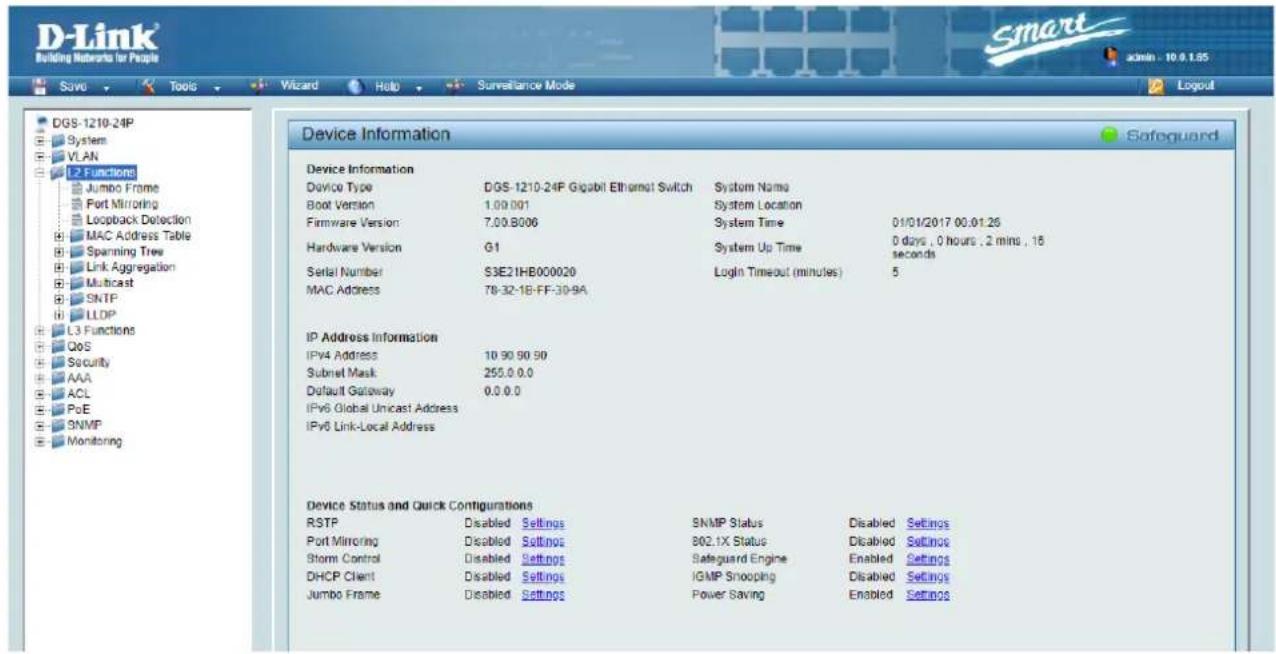
- Connect your computer to the D-Link Ethernet Switch using an Ethernet cable. D-Link DSG-1210 Ethernet Switches come with a default Static IP address of 10.90.90.90;
- Configure your PC with a Static IP address in the same subnet such as 10.90.90.66, with subnet mask 255.0.0.0.
- Open your Internet browser and type the default IP address of the switch: http://10.90.90.90. The default Password is "admin".
27 ENABLING IGMP PROTOCOL
Internet Group Management Protocol (IGMP) is mandatory for the correct operation of VEO over IP products when they are configured as multicast devices. Without IGMP enabled, audio/video signal can't be transmitted properly or it may freeze.
With IGMP snooping, the Smart Managed Switch can make intelligent multicast forwarding decisions by examining the content of each frame's Layer 2 MAC header. IGMP snooping can help reduce cluttered traffic on the LAN. With IGMP snooping enabled, the Smart Managed Switch will forward multicast traffic only to connections that have group members attached.
-
Select L2 Function→Multicast→IGMP Snooping
-
Enable IGMP Snooping by activating the related selection box and clicking on Apply.

text_image
IGMP Snooping Configuration IGMP Snooping Global Settings IGMP Snooping Enabled Disabled Report to all ports Host Timeout (130-153025) 260 sec Router Timeout (60-600) 125 sec Robustness Variable (2-255) 2 Lost Member Query Interval (1-25) 1 sec Query Interval (60-600) 125 sec Max Response Time (10-25) 10 sec IGMP Snooping MLD Snooping Multicast Forwarding When Quenier state is enabled, the Host Timeout is calculated as the formula : ( Host Timeout = Robustness Variable * Query Interval - Max Response Time ) Apply- Select Save in the upper left corner and press Save Config button in order to ensure that all changes are saved as current configuration in use.

text_image
Save Tools Wizard Help Surveillance Mode DGS-1210-24P System VLAN L2 Functions Jumbo Frame Port Mirroring Save Configuration Please press the button to save the config of device. config_id 1 Save Config28 ENABLING Jumbo Frame
D-Link Gigabit Smart Managed Switches support jumbo frames (frames larger than the Ethernet frame size of 1536 bytes) of up to 9216 bytes (tagged). It is disabled by default.
2. Select L2 Function→Jumbo Frame
text_image
DGS-1210-24P System VLAN L2 Functions Jumbo Frame Fort Mirroring Loopback Detection MAC Address Table Spanning Tree Link Aggregation Multicast SNTP LLDP L3 Functions QoS Security AAA ACL PoE SNMP Monitoring Device Information Device Information Device Type DGS-1210-24P Gigabit Ethernet Switch System Name Boot Version 1.09.001 System Location Firmware Version 7.00.8006 System Time 01/01/2017 00:01:26 Hardware Version G1 System Up Time 0 days , 0 hours , 2 mins , 15 seconds Serial Number S3E21HB000020 Login Timeout (minutes) 5 MAC Address 78-32-18-FF:30-9A IP Address Information IPv4 Address 10.90.90.90 Subnet Mask 255.0.0.0 Default Gateway 0.0.0.0 IPv6 Global Unicast Address IPv6 Link-Local Address Device Status and Quick Configurations RSTP Disabled Settings SNMP Status Disabled Settings Port Mirroring Disabled Settings 802.1X Status Disabled Settings Storm Control Disabled Settings Safeguard Engine Enabled Settings DHCP Client Disabled Settings IGMP Snooping Disabled Settings Jumbo Frame Disabled Settings Power Saving Enabled Settings- Enable Jumbo Frame by activating the related selection box and click on Apply.

text_image
DGS-1210-24P System VLAN L2 Functions Jumbo Frame Port Mirroring Loopback Detection Jumbo Frame Settings Jumbo Frame Enabled Disabled Maximum Length is 10000 bytes. Safeguard Apply- Select Save in the upper left corner and press Save Config button in order to ensure that all changes are saved as current configuration in use.

text_image
Save Tools Wizard Help Surveillance Mode DGS-1210-24P System VLAN L2 Functions Jumbo Frame Port Mirroring Save Configuration Please press the button to save the config of device. config_id 1 ▼ Save Config29 Disabling POWER Saving and EEE (Energy Efficient Ethernet)
In order to prevent audio or video drops out, all the power saving features need to be disabled. This is a mandatory requirement for Dante™ Networks.
- Select System → Power Saving
- On Global Settings disable Cable Length Detection/Link Status Detection and press Apply

text_image
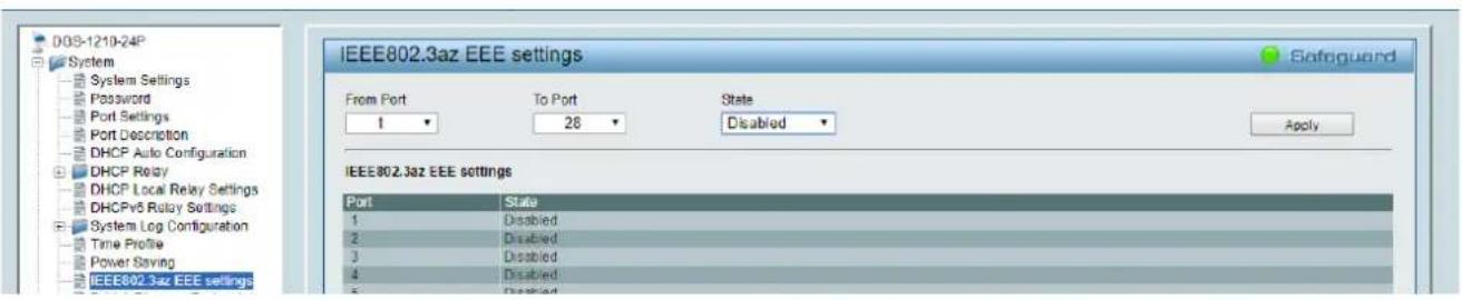
DGS-1210-24P System System Settings Password Port Settings Port Description Power Saving Settings Global Settings Cable Length Detection/Link Status Detection Enabled Disabled Safeguard Apply- Select IEEE802.3az EEE settings and ensure that the feature is disabled on the ports where Dante or VEO devices are connected
text_image
DOS-1210-24P System System Settings Password Port Settings Port Description DHCP Auto Configuration DHCP Relay DHCP Local Relay Settings DHCPv5 Relay Settings System Log Configuration Time Profile Power Saving IEEE802.3az EEE settings IEEE802.3az EEE settings From Port 1 To Port 28 State Disabled Apply IEEE802.3az EEE settings Port State 1 Disabled 2 Disabled 3 Disabled 4 Disabled 5 Disabled- Select Save in the upper left corner and press Save Config button in order to ensure that all changes are saved as current configuration in use.

text_image
Save Tools Wizard Help Surveillance Mode DGS-1210-24P System VLAN L2 Functions Jumbo Frame Port Mirroring Save Configuration Please press the button to save the config of device. config_id 1 Save Config30 CREATING VLANS FOR DANTE™, VIDEO OVER IP AND CONTROL COEXISTENCE
In AV system where Dante ^™ and Video over IP traffic are sharing the same network switch, VLANs are highly recommended because Video over IP could interfere with Dante ^™ in the same network.
A VLAN allows isolating the network traffic of a predefined group of ports; in case of Audio and Video systems we need to create two VLANs: one for Audio and one for Video. In this case, a device connected to the Audio VLAN can't communicate with a device connected to the Video VLAN.
When a control device (like a touch panel) is required, it needs to communicate both with Audio and Video devices; in this case we need to use a particular feature called Asymmetric VLAN that allows sharing traffic between different VLANs only on predefined ports.
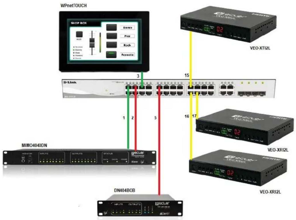
In the following example (Fig. 1) we have:
- MIMO4040DN matrix with Dante™ (Control on port 1; Dante on port 2)
• WPNETTOUCH (Control on port 3)
• DN404BOB (Dante/Control on port 5)
• VEO-XTI2L (Video/Control on port 15)
• VEO-XRI2L (Video/Control on port 16)
• VEO-XRI2L (Video/Control on port 17)
We need to create 2 VLANs like follows:
1 Audio/Control VLAN (default): Ports 1-14
2 Video/Control VLAN: Ports 15-28
flowchart
graph TD
A["WPnetTOUCH"] -->|Dance| B["SHOP BCN"]
A -->|Pop| C["D-Link"]
A -->|Rock| D["VEO-XTI2L"]
A -->|Acoustic| E["MIMO4040DN"]
A -->|1 2 5| F["DN404BCB"]
A -->|15 16 17| G["VEO-XRI2L"]
A -->|1 2 5| H["VEO-XTI2L"]
Fig. 1
- Select VLAN→802.1Q VLAN, enable Asymmetric VLAN and click on Apply

text_image
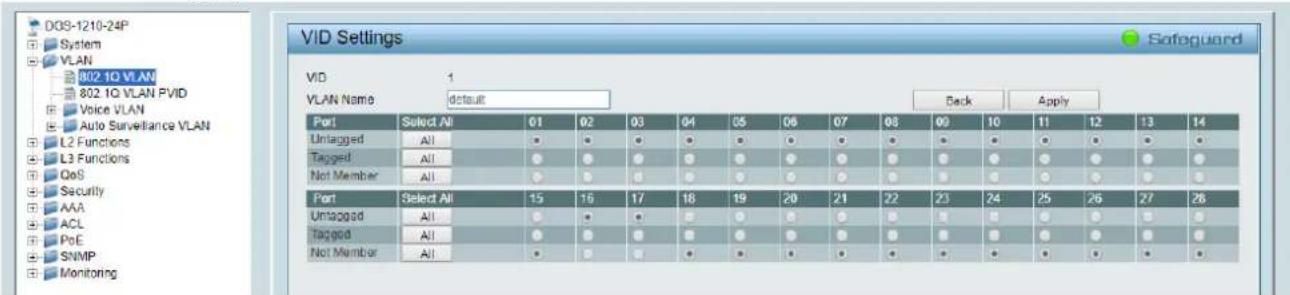
DGS-1210-24P System VLAN 802.1Q VLAN 802.1Q VLAN PVID Voice VLAN 802.1Q Asymmetric VLAN Settings Asymmetric VLAN [Example] Enabled Disabled Safeguard Apply- Click on 1 and mark as Untagged all the Audio/Control VLAN ports (1-14), adding the Video/Control VLAN ports that need to share Control (16-17). Click on the Apply button.
7. Create a second VLAN for Video/Control by clicking on Add button

text_image
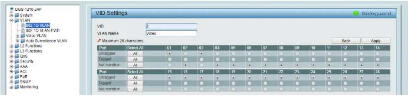
B02.1Q Asymmetric VLAN Settings Asymmetric VLAN [Example] Enabled Disabled Total static VLAN entries: 1 Maximum 256 entries. VID VLAN Name Untagged Tagged Delete 1 default 01-14.16-17 Delete8. Assign 2 as VID, and Video as Name to the new VLAN; mark as Untagged all the Video/Control VLAN ports (15-28), adding the Audio/Control VLAN ports that need to share Control traffic (1-3). Click on the Apply button.
text_image
DGS-1210-24P System VLAN 802.1Q VLAN 802.1Q VLAN PVID Voice VLAN Auto Surveillance VLAN L2 Functions L3 Functions QoS Security AAA ACL PoE SNMP Monitoring VID 2 VLAN Name: Video Maximum 20 characters Port Select All 01 02 03 04 05 06 07 08 09 10 11 12 13 14 Untagged All ● ● ● ● ● ● ● ● ● ● ● ● ● ● ● ● Tagged All ● ● ● ● ● ● ● ● ● ● ● ● ● ● ● ● ● ● Not member All ● ● ● ● ● ● ● ● ● ● ● ● ● ● ● ● ● Port Select All 15 16 17 18 19 20 21 22 23 24 25 26 27 28 Untagged All ● ● ● ● ● ● ● ● ● ● ● ● ● ● ● ● Tagged All ● ● ● ● ● ● ● ● ● ● ● ● ● ● ● ● ● Not member All ● ● ● ● ● ● ● ● ● ● ● ● ● ● ●9. Select Save in the upper left corner and press Save Config button in order to ensure that all changes are saved as current configuration in use.


text_image
Save Tools Wizard Help Surveillance Mode DGS-1210-24P System VLAN L2 Functions Jumbo Frame Port Mirroring Save Configuration Please press the button to save the config of device. config_id 1 Save Config
ecler
VIDEO SYSTEMS