SC-323 - Speaker QSC - Free user manual and instructions
Find the device manual for free SC-323 QSC in PDF.


| Product Type | Low-frequency loudspeaker (subwoofer) for cinema |
| Model | LF-3215 (component of SC-323 system) |
| Dimensions (W x H x D) | 762 mm x 889 mm x 508 mm |
| Net weight | 78 kg |
| Gross weight | 88 kg |
| Nominal impedance | 4 ohms |
| Power handling (RMS) | 600 W (8 h) / 750 W (2 h) |
| Recommended amplifier power | Up to 1200 W RMS into 4 ohms |
| Sensitivity (1 W/1 m) | 98.5 dB (half-space) |
| Frequency response (-6 dB) | 32 Hz – 1500 Hz |
| Frequency response (-10 dB) | 28 Hz – 3300 Hz |
| Calculated maximum SPL | 132.5 dB SPL at 1 m (half-space) |
| Nominal coverage (at 600 Hz) | 100° horizontal x 55° vertical |
| Transducers | 2 x 381 mm (15") with 76 mm voice coil, 3.4 kg ceramic magnet |
| Connectors | Screw terminals (4 terminals, accept up to 10 AWG cable) |
| Enclosure type | Symmetrical vented loading, tuned to 36 Hz, reinforced MDF panels |
| Features | Parallel outputs for daisy-chaining, mounting points for HF systems (HF-63 / MH-1063) |
| Recommended filter | Subsonic < 30 Hz, slope > 18 dB/octave; high-pass max 1000 Hz |
| Warranty (USA) | 3-year limited |
| Intended use | Fixed installation in cinema (do not suspend) |
| Maintenance | Regularly inspect screws and suspension hardware (if present) |
| Safety | High sound levels – protect hearing; professional installation |
Frequently Asked Questions - SC-323 QSC
User questions about SC-323 QSC
0 question about this device. Answer the ones you know or ask your own.
Ask a new question about this device
Download the instructions for your Speaker in PDF format for free! Find your manual SC-323 - QSC and take your electronic device back in hand. On this page are published all the documents necessary for the use of your device. SC-323 by QSC.
USER MANUAL SC-323 QSC
- Three-way selectable, bi or tri-amplified screen channel system
- MH-1063 provides 90^ horizontal by +20^ to -30^ vertical coverage
• LF-3215 is constructed of MDF and is heavily braced - Low-distortion waveguides provide highly articulate dialogue
- Shallow depth (20") facilitates installation
- THX™ approved for professional cinema applications
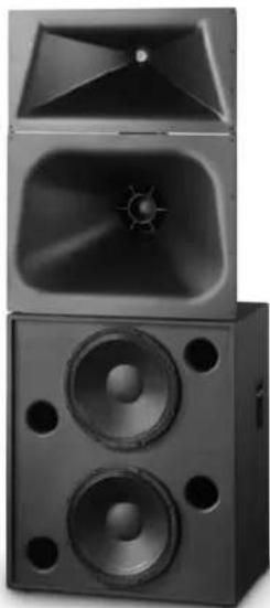
natural_image
Exterior view of a black speaker tower with two speakers and a speaker grille (no text or symbols visible)THX
Developed specifically for the unique requirements of professional motion picture playback, the SC-323 extends QSC's commitment to the cinema market. As a member of the DCS Digital Cinema Speaker Series, the SC-323 is a three-way, selectable bi or tri-amplified screen channel loudspeaker system comprised of two main units—the MH-1063 mid-high frequency system and the LF-3215 low-frequency system.
The MH-1063 mid-high system features a high output, horn loaded 10" midrange cone driver and a 2.5" (63mm) titanium diaphragm compression driver mounted to an adjustable pan and tilt bracket. The MH-1063 includes a driver protection network and a passive crossover for bi-amp operation. Power limiter circuitry protects the high-frequency driver from overpowering. The MH-1063 provides extended frequency coverage for the critical midrange band. A high power 10" cone driver allows operation as low as 250 Hz and the advanced phase plug coupling permits a crossover point of up to 1800 Hz to the high-frequency horn. This ensures that most of the dialog range is reproduced by a single element, for unmatched intelligibility.
The LF-3215 dual 15" (381mm) low-frequency enclosure is designed specifically to address the extended low-frequency response required for cinema applications. The LF-3215 covers the frequency range from 35 Hz to 250 Hz. Close Coupled Woofers (CCW), with their tight spacing between woofers, improves coupling and keeps coverage angles wide over a greater frequency range than more widely spaced designs.
The SC-323 is designed for ease of installation. The MH-1063 components come pre-assembled to reduce field assembly time. Three bolts are all that are required to secure the MH-1063 to the top of the LF-3215 enclosure.
Specifications SC-323
| Nominal Coverage 90° horizontal x +20 to -30° vertical | |||
| Frequency Range 32 Hz - 16 kHz (-6 dB) | |||
| Crossover Frequency | 250 and 1700 Hz, 24 dB per octave | ||
| LF-3215 | MH-1063 | ||
| Impedance | 4Ω | 8Ω | |
| Sensitivity 1 watt/1 meter, half space | 98.5 dB | Bi-amp105 dB | Tri-ampMF 105 dB HF 107.5 dB |
| Maximum Input Power1 | |||
| 8 hours of 6 db crest factor IEC 268 noise spectrum | 600 W RMS | 250 W RMS2passive mid-high | 275 W RMS 60 W RMS |
| 2 hours of 6 db crest factor pink noise, 50 Hz - 20 kHz, AES method | 800 W RMS | 350 W RMS | |
| Recommended Amplifier Power | 1200 W RMS maximum | 800 W RMS maximum | |
| Recommended Processing | Subsonic filter below 30 Hz, >18 dB per octave | 4th order LR crossover at 200 and 1700 Hz via QSC DCM or QSControl.net | |
| Connectors | Barrier strip screw terminals accept up to #10 AWG stranded wire, four terminals; two inputs and two parallel outputs | Barrier strip screw terminals accept up to #10 AWG stranded wire | |
| Transducers | Two 15" (381mm) high efficiency, extended bass woofer featuring 3" copper voice coils | 10" high efficiency mid range, 1.5" (38mm) exit, 2.5" titanium diaphragm compression driver | |
| Enclosure | Quasi B4 alignment, ported enclosure with fully flared ports, symmetrical port design, tuned to 36 Hz, constructed of MDF and heavily braced. Features vandal resistant woofer mounting bolts | Tilt/Pan Bracket ±10° vertical tilt ±10° horizontal pan | |
| Dimensions (HWD) | 36" x 30" x 20.3"(910 mm x 762 mm x 516 mm) | 39" x 30" x 20"(990 mm x 762 mm x 508 mm) | |
| Weight - Net | 172 lbs (78 kg) | 85 lbs (39 kg) | |
| System Weight | 257 lbs (117 kg) | ||
| Baffle Cut-Out | 76" x 32" | ||
1) Maximum input power tested in accordance with IEC 268-5 recommendations, 50 Hz - 20 kHz band limiting, 6 dB signal crest factor. 2) Maximum input power tested in accordance with IEC 268-5 recommendations, 200 Hz - 2 kHz band limiting, 6 dB signal crest factor.

Specifications subject to change without notice.
Cinema Mid-High Loudspeaker System User Manual
MH-1063 10" (254mm) mid, 2.5" (63mm) compression driver
MH-1075 10" (254mm) mid, 3.0" (75mm) compression driver
Introduction
The MH-1063 and MH-1075 "mid-high packs" provide the mid and high frequency components of three-way screen channel loudspeaker systems for high performance cinema applications. They were designed to operate with and be directly mounted on QSC's cinema low frequency enclosures.
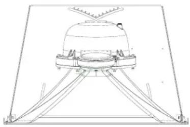
Mid frequencies are reproduced with a 10" (254mm) high-efficiency, phase-ring loaded driver mounted on a custom designed cinema horn. The high-frequency driver is a large format, 2.5" (63mm, MH-1063) or 3.0" (75mm, MH-1075) titanium diaphragm compression driver mounted on a custom high-frequency cinema horn. The high frequency horn is a low-distortion waveguide providing highly articulate dialogue without coloration associated with conventional horn loudspeakers. Both horns feature broad horizontal and vertical coverage angles to ensure coverage of every seat in the auditorium. The driver assemblies are mounted on an adjustable pan and tilt bracket that has an integral aiming sight, simplifying installation.
The MH-1063 and MH-1075 loudspeakers include a driver protection and crossover network to assure reliable operation. DC blocking capacitors protect against DC or low-frequency signals that could damage an unprotected driver. Power limiter circuitry protects the driver from over-powering and an 18dB/octave crossover seamlessly blends the high and mid frequency elements. Outboard processing is required to form the crossover between the LF and MH loudspeakers.
Bi-amp or tri-amp operation is possible using a selector switch mounted on the connections panel. The bi-amp setting provides a passive crossover network between mid and high drivers. Separate amplifiers and an active crossover are required for the low frequency channel and the mid-high channel. Tri-amp setting disables the internal mid-high crossover and each driver is driven independently by its own amplifier and active crossover; one for the low, one for the mid, and one for the high frequencies.
The MH-1063 and MH-1075 components come pre-assembled to reduce field assembly time. Three bolts are all that are required to secure the mid-high assembly to the top of a QSC low frequency enclosure.

Install in accordance with QSC Audio Product's instructions and a licensed, professional engineer. Only use attachments, mounts, accessories, or brackets specified by QSC Audio Products, Inc. Refer all servicing to qualified personnel. Servicing is required when the apparatus has been damaged in any way.

WARNING! Before placing, installing, rigging, or suspending any speaker product, inspect all hardware, suspension, cabinets, transducers, brackets and associated equipment for damage. Any missing, corroded, deformed or non-load rated component could significantly reduce the strength of the installation, placement, or array. Any such condition severely reduces the safety of the installation and should be immediately corrected. Use only hardware which is rated for the loading conditions of the installation and any possible short-term unexpected overloading. Never exceed the rating of the hardware or equipment. Consult a licensed, professional engineer when any doubt or questions arise regarding a physical equipment installation.
natural_image
Technical line drawing of a mechanical assembly with tripod supports and a dome-shaped component (no text or symbols)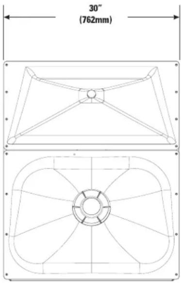
text_image
30" (762mm)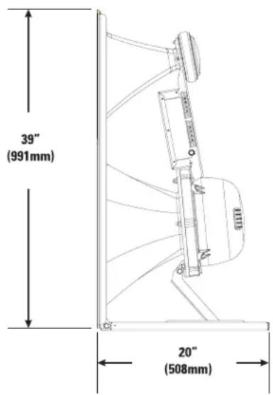
text_image
39" (991mm) 20" (508mm)
TD-000180-00 rev.A
© Copyright 2004, QSC Audio Products, Inc.
QSC® is a registered trademark of QSC Audio Products, Inc.
"QSC" and the QSC logo are registered with the U.S. Patent and Trademark Office
Mounting
Attaching to Low Frequency Enclosure
The mid-high loudspeaker assembly attaches to the top of the QSC low frequency cabinet with three 5/16-18 bolts, 0.75" long, with lock washers. This hardware ships installed on the low frequency cabinet. We recommend the use of serviceable thread locking compound when installing the bolts to prevent loosening due to vibration. Do not fully tighten the mounting hardware before aiming (see below).
Aiming
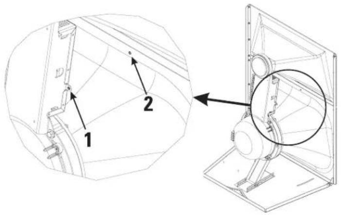
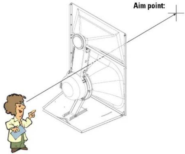
Aim the horn in the horizontal plane (pan) before tightening the attachment hardware. Adjust the vertical tilt with the mid-high vertical adjustment bracket. The mid-high assembly is equipped with an aiming sight to assist in achieving desired coverage quickly and easily. For typical applications, the aim point should be the center seat in the back row of the auditorium. If the cinema screen has already been installed, a flashlight placed at the desired aiming point can be seen through the screen perforations in a darkened auditorium.
Where the sight holes are located:
text_image
Technical diagram showing mechanical assembly with labeled parts 1 and 2, including a magnified inset view.How to use the sights:
text_image
Aim point:Settings
BI-AMP / TRI-AMP Operating Mode Selection
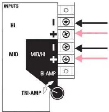
Set the operating mode selector switch to BI-AMP or TRI-AMP, depending on your application setup.

text_image
INPUTS HI MID MID/Hi BI-AMP TRI-AMPBI-AMP-When set to BI-AMP, the MH-1063 and MH-1075 accepts mid-high frequency signals on one set of inputs and uses an internal crossover network between the mid- and high-frequency drivers. The signal applied to the mid-high loudspeaker assembly must not contain low-frequency content (below 200 Hz).
text_image
INPUTS HI MID MID/HI BI-AMP TRI-AMPTRI-AMP- When set to TRI-AMP, the MH-1063 and MH-1075 accepts separate mid- and high-frequency signals on two sets of inputs. The internal crossover network is bypassed and only the protective circuitry for the H.F. driver remains. Each of the driver's signals must have the appropriate signal processing before operating.

Do not connect amplifiers directly to the driver inputs! Always use the input terminal strip.
Connections
INPUT Terminals
The MH-1063 and MH-1075 have barrier strip screw terminals that accept up to #10 AWG (5.3mm ^2 ) stranded loudspeaker wire.
Observe proper polarity. Use the largest wire size and shortest wire length for the application.
OUTPUT Terminals
The OUTPUT terminals are factory-connected to the drivers. These terminals should ONLY be connected to their respective driver. Do not connect signals to these terminals as all protection and equalization circuitry will be bypassed.

NOTE! Maintain proper loudspeaker connection polarity throughout the entire system for maximum performance. Do not apply full range signal to the MH-1063 / MH-1075! There is a mid-high passive crossover for bi-amp mode only. There is no crossover connected when operating in tri-amp mode. A protection network is always active. All required signal processing must be done before the signal is applied to the loudspeaker. Do not connect any signal to the upper sets of OUTPUT terminals.
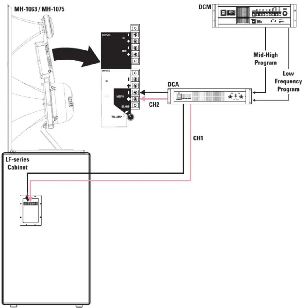
BI-AMP mode connections- Ensure the mode switch is set to BI-AMP, connect the input to the MH-1063 / MH-1075 to the lower set of input terminals marked "BI-AMP + -".
BI-AMP Mode- one amplifier channel is used for the low frequency cabinet and one amplifier channel for the mid-high assembly. The MH-1063/MH-1075 mode switch is set to BI-AMP. Active crossovers are used before amplification. The mid-high assembly provides a passive crossover between the mid and high frequency drivers.
flowchart
graph TD
    A["MH-1063 / MH-1075"] --> B["LV-series Cabinet"]
    B --> C["DCA"]
    C --> D["DCM"]
    D --> E["Mid-High Program"]
    D --> F["Low Frequency Program"]
    B --> G["CH1"]
    B --> H["CH2"]
    B --> I["INPUTS"]
    B --> J["BI-AMP"]
    B --> K["THA-AMP"]
    style A fill:#f9f,stroke:#333
    style B fill:#ccf,stroke:#333
    style C fill:#cfc,stroke:#333
    style D fill:#fcc,stroke:#333
    style E fill:#ffc,stroke:#333
    style F fill:#fcc,stroke:#333
    style G fill:#cff,stroke:#333
    style H fill:#ffc,stroke:#333
    style I fill:#ffc,stroke:#333
    style J fill:#ffc,stroke:#333
    style K fill:#ffc,stroke:#333
Connections (continued)
TRI-AMP mode connections- When the mode switch is set to TRI-AMP, connect the high frequency signal to the terminals marked "INPUT HI + -" and the mid frequency signal to the terminals marked "INPUT MID + -".
TRI-AMP Mode- one amplifier channel is used for the low frequency cabinet, one amplifier channel for the mids, and one amplifier channel for the high frequencies. The MH-1063 / MH-1075 mode switch is set to TRI-AMP, bypassing the internal mid-high passive crossover. Active or passive crossovers are used before amplification. Power limiter and DC blocking remain active.
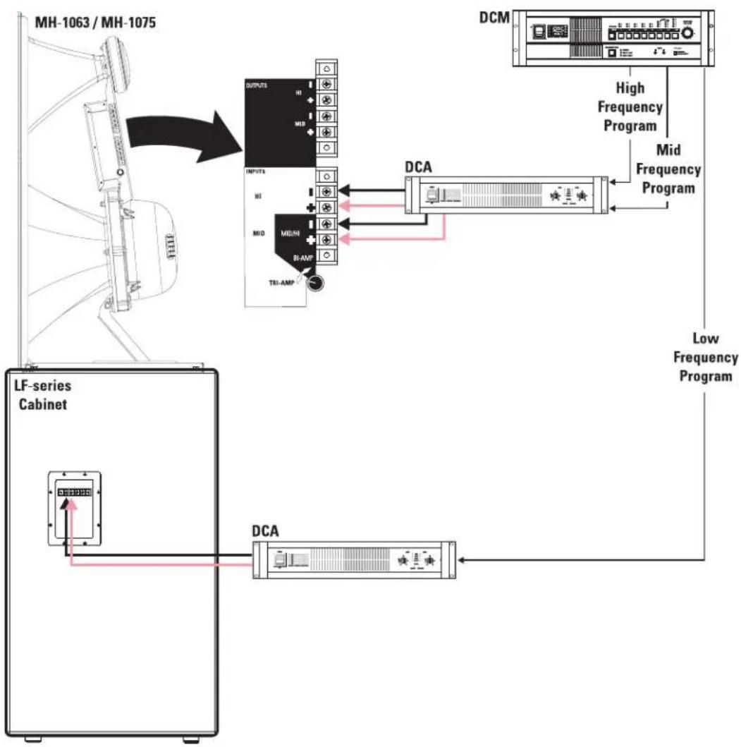
flowchart
graph TD
    A["MH-1063 / MH-1075"] --> B["LV-series Cabinet"]
    B --> C["DCA"]
    C --> D["DCM"]
    D --> E["High Frequency Program"]
    D --> F["Mid Frequency Program"]
    D --> G["Low Frequency Program"]
    B --> H["DCA"]
    H --> I["Inputs"]
    I --> J["OUTPUTS HI MID"]
    I --> K["MID MID"]
    I --> L["BI-AMP TRI-AMP"]
MH-1063 Specifications (subject to change without notice)
Freq. Range 180 - 15k (-6dB, full space)
Nominal Coverage
90° horizontal X +20 to -30° vertical (50° total, adjustable mount provides for vertical plane adjustments. The horizontal plane can be adjusted by altering mounting position on the low frequency enclosure before tightening bolts.
DI: 9 dB (400 to 16k Hertz average)
Q: 8 (400 to 16k Hertz average)
Max. Output: [Tri-amp mode] Mid Freq. 135.5 dB SPL calculated peak, 1m, full space
[Tri-amp mode] High Freq. 131.5 dB SPL calculated peak, 1m, full space
[Bi-amp mode] 135 dB SPL calculated peak, 1m ,full space
Impedance: [Bi-amp mode] 8 ohms nominal
7.9 ohms minimum at 1500 Hertz
91 ohms maximum at 150 Hertz
Maximum Input Power [Tri-amp mode] Mid Freq. 275 W (AES method, 2 hrs.)
[Tri-amp mode] High Freq. 60 W (AES method, 2 hrs.)
[Bi-amp mode] 250 W (IEC method, 8 hrs.)
Sensitivity [Tri-amp mode] Mid Freq. 105 dB SPL, 1 watt, 1 meter
[Tri-amp mode] High Freq. 107.5 dB SPL, 1 watt, 1 meter
[Bi-amp mode] 135 dB SPL, 1 watt, 1 meter
Crossover Frequency
[Tri-amp mode] 250 Hertz or higher, 24dB/octave and 1.7k Hertz, 24dB/octave
[Bi-amp mode] 250 Hertz or higher, 24dB/octave
Crossover Network
1.7k Hertz, 18 dB/octave electrical slope, HF driver power limiting circuit (never disrupts continuity). Switchable operation between Bi-Amp and Tri-amp operation. Tri-amp setting removes crossover circuit from signal, leaving power limiter and DC blocking capacitors.
Connectors
Barrier strip screw terminals accept up to #10 AWG stranded wire. Four terminals, two HF input and two MF input (for Tri-amp mode operation).
Transducers MF: 10" high efficiency midrange, phase-ring loaded.
HF: 1.5" (38mm) exit, 2.5" (63.5mm) titanium diaphragm compression driver.
Mounting Hardware:
Attaches to top of the low frequency cabinet using three 5/16"-18 x 3/4" long bolts.
Size
39" high x 30" wide x 20" deep (991 x 762 x 508mm)
Weight
85 lb. (39 kg) net
MH-1075 Specifications (subject to change without notice
Freq. Range 180 - 15k (-6dB, full space)
Nominal Coverage
90° horizontal X +20 to -30° vertical (50° total, adjustable mount provides for vertical plane adjustments. The horizontal plane can be adjusted by altering mounting position on the low frequency enclosure before tightening bolts.
DI: 9 dB (400 to 16k Hertz average)
Q: 8 (400 to 16k Hertz average)
Max. Output: [Tri-amp mode] Mid Freq. 135.5 dB SPL calculated peak, 1m, full space
[Tri-amp mode] High Freq. 133 dB SPL calculated peak, 1m, full space
[Bi-amp mode] 135.5 dB SPL calculated peak, 1m ,full space
Impedance: [Bi-amp mode] 8 ohms nominal
6.4 ohms minimum at 1500 Hertz
91 ohms maximum at 150 Hertz
Maximum Input Power [Tri-amp mode] Mid Freq. 275 W (AES method, 2 hrs.)
[Tri-amp ode] High Freq. 80 W (AES method, 2 hrs.)
[Bi-amp mode] 250 W (IEC method, 8 hrs.)
Sensitivity [Tri-amp mode] Mid Freq. 105 dB SPL, 1 watt, 1 meter
[Tri-amp mode] High Freq. 108 dB SPL, 1 watt, 1 meter
[Bi-amp mode] 135.5 dB SPL, 1 watt, 1 meter
Crossover Frequencies
[Tri-amp mode] 250 Hertz or higher, 24dB/octave and 1.7k Hertz, 24dB/octave
[Bi-amp mode] 250 Hertz or higher, 24dB/octave
Crossover Network
1.7k Hertz, 18 dB/octave electrical slope, HF driver power limiting circuit (never disrupts continuity). Switchable operation between Bi-Amp and Tri-amp operation. Tri-amp setting removes crossover circuit from signal, leaving power limiter and DC blocking capacitors.
Connectors
Barrier strip screw terminals accept up to #10 AWG stranded wire. Four terminals, two HF input and two MF input (for Tri-amp mode operation).
Transducers MF: 10" high efficiency midrange, phase-ring loaded.
HF: 1.5" (38mm) exit, 3" (76mm) titanium diaphragm compression driver.
Mounting Hardware:
Attaches to top of the low frequency cabinet using three 5/16"-18 x 3/4" long bolts.
Size
39" high x 30" wide x 20" deep (991 x 762 x 508mm)
Weight
85 lb. (39 kg) net
MH-1063 SPL and Impedance vs. Frequency
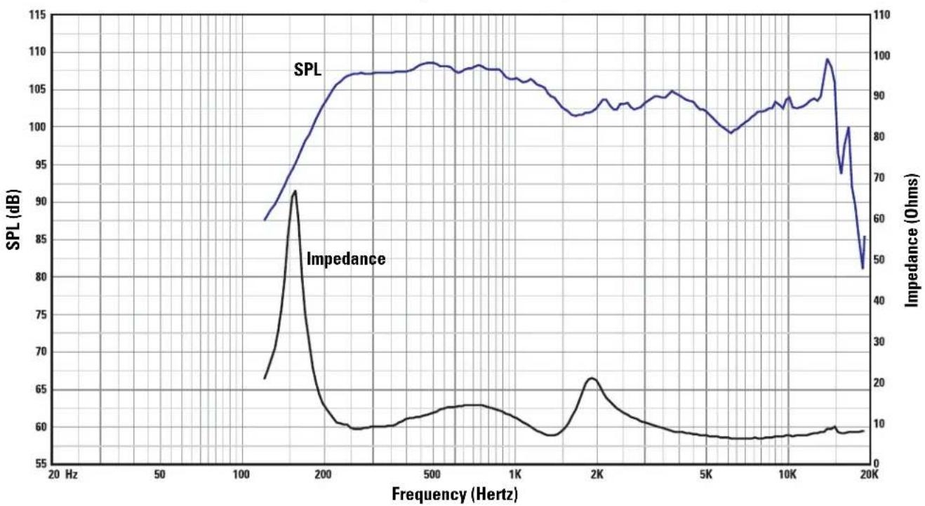
bar_line
| Frequency (Hz) | SPL (dB) | Impedance (Ohms) | | -------------- | -------- | ---------------- | | 20 | 87 | 0 | | 150 | 91 | 20 | | 100 | 107 | 10 | | 500 | 108 | 15 | | 1K | 107 | 10 | | 5K | 103 | 5 | | 10K | 104 | 5 | | 15K | 109 | 10 | | 20K | 82 | 5 |MH-1075 SPL and Impedance vs. Frequency
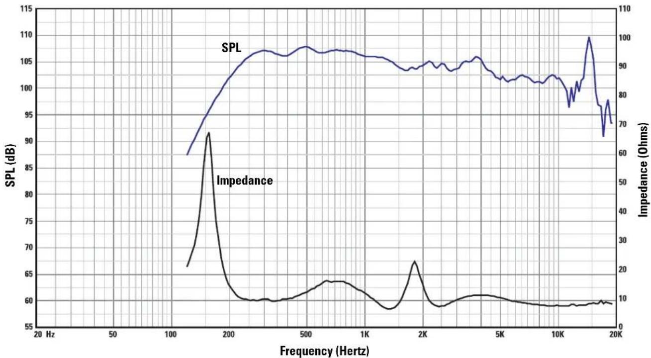
bar_line
| Frequency (Hz) | SPL (dB) | Impedance (Ohms) | | -------------- | -------- | ---------------- | | 20 | 67 | 10 | | 150 | 92 | 30 | | 100 | 60 | 10 | | 500 | 107 | 15 | | 1K | 106 | 10 | | 2K | 104 | 25 | | 5K | 103 | 10 | | 10K | 102 | 10 | | 15K | 100 | 70 | | 20K | 70 | 10 |Warranty (USA only; other countries, see your dealer or distributor)
Disclaimer
QSC Audio Products, Inc. is not liable for any damage to amplifiers, or any other equipment that is caused by negligence or improper installation and/or use of this loudspeaker product.
QSC Audio Products 3 Year Limited Warranty
QSC Audio Products, Inc. ("QSC") guarantees its products to be free from defective material and / or workmanship for a period of three (3) years from date of sale, and will replace defective parts and repair malfunctioning products under this warranty when the defect occurs under normal installation and use - provided the unit is returned to our factory or one of our authorized service stations via pre-paid transportation with a copy of proof of purchase (i.e., sales receipt). This warranty provides that the examination of the return product must indicate, in our judgment, a manufacturing defect. This warranty does not extend to any product which has been subjected to misuse, neglect, accident, improper installation, or where the date code has been removed or defaced. QSC shall not be liable for incidental and/or consequential damages. This warranty gives you specific legal rights. This limited warranty is freely transferable during the term of the warranty period.
Customer may have additional rights, which vary from state to state.
In the event that this product was manufactured for export and sale outside of the United States or its territories, then this limited warranty shall not apply. Removal of the serial number on this product, or purchase of this product from an unauthorized dealer, will void this limited warranty. Periodically, this warranty is updated. To obtain the most recent version of QSC's warranty statement, please visit www.qscaudio.com. Contact us at 800-854-4079 or visit our website at www.qscaudio.com.
Contacting QSC Audio Products
Mailing address: QSC Audio Products, Inc.
1675 MacArthur Boulevard
Costa Mesa, CA 92626-1468 USA
Telephone Numbers:
Main Number (714) 754-6175
Sales & Marketing (714) 957-7100 or toll free (USA only) (800) 854-4079
Customer Service(714) 957-7150 or toll free (USA only) (800) 772-2834
Facsimile Numbers:
Sales & Marketing Fax(714) 754-6174
Customer Service Fax(714) 754-6173
World Wide Web:www.qscaudio.com
E-mail:info@qscaudio.com
service@qscaudio.com
Cinema Loudspeaker Systems User Manual
LF-3215 Low Frequency Loudspeaker
Introduction
The LF-3215 dual 15" (381mm) low frequency enclosure is designed specifically for cinema applications. Meeting cinema requirements for extended low frequency response differentiates the LF-3215 from more conventional "rock-and-roll" woofer systems. The LF-3215 covers the frequency range from 32 Hertz to 1500 Hertz, depending upon the high frequency system requirements. With its tight spacing between woofers, the LF-3215 offers improved coupling and keeps coverage angles wide over a greater frequency range than more widely spaced designs.
The 300 watt, 15" transducers are well suited for cinema use. They feature 3" (76mm) voice coils, 120 oz.(3.4kg) ceramic magnets, and vented pole pieces to ensure cool operation. Cooler temperatures increase transducer lifespan and decrease the problem of power compression at high power levels. The suspension and voice coil of each transducer have been designed to provide low distortion and high impact bass at high power levels.
The enclosure is constructed of high quality medium density fiberboard panels with stiffening braces on all panels and features separate woofer chambers. This prevents over-excursion of a transducer caused by improper box loading in the rare event of a transducer failure. The eight stiffening braces reduce panel resonance.
Both internal and external port openings are fully radiused ensuring smooth air flow at high power. This prevents audible port turbulence noise.
With symmetrical port loading, bass ports are evenly spaced on each side of the transducers, making internal pressure more uniform across the back surface of the transducer. This prevents the cone from being displaced to one side or another by unbalanced forces, reducing the chance of driving the voice coil out of the center of the gap at high power levels.
Three T-nuts in the top of the enclosure provide easy mounting of QSC's HF-63 high frequency system, or MH-1063 mid-high frequency system.

Enclosure is not designed to be suspended, flown, or rigged. Do not suspend, fly, or rig this enclosure.
This product is capable of producing sound pressure levels that can permanently damage human hearing. Always keep sound pressure levels in the listening area below levels that can damage human hearing.
Install in accordance with QSC Audio Product's instructions and a licensed, professional engineer. Only use attachments, mounts, accessories, or brackets specified by QSC Audio Products, Inc. Refer all servicing to qualified personnel. Servicing is required when the apparatus has been damaged in any way.

WARNING! Before placing, installing, rigging, or suspending any speaker product, inspect all hardware, suspension, cabinets, transducers, brackets and associated equipment for damage. Any missing, corroded, deformed or non-load rated component could significantly reduce the strength of the installation, placement, or array. Any such condition severely reduces the safety of the installation and should be immediately corrected. Use only hardware which is rated for the loading conditions of the installation and any possible short-term unexpected overloading. Never exceed the rating of the hardware or equipment. Consult a licensed, professional engineer when any doubt or questions arise regarding a physical equipment installation.
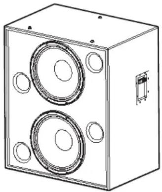
natural_image
Technical line drawing of a two-tiered speaker chamber with circular cutouts and mounting holes (no text or symbols)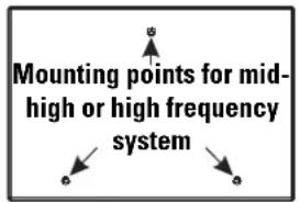
text_image
Mounting points for mid- high or high frequency system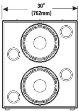
text_image
30" (762mm)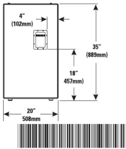
text_image
4" (102mm) 35" (889mm) 18" 457mm) 20" 508mmTD-000173-00 rev.C
© Copyright 2004, QSC Audio Products, Inc.
QSC® is a registered trademark of QSC Audio Products, Inc.
"QSC" and the QSC logo are registered with the U.S. Patent and Trademark Office
Connections
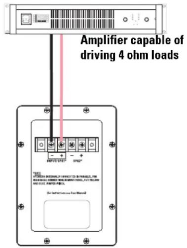
Normal Connection
The LF-3215 has barrier strip screw terminals for connection. The terminals accept up to #10 AWG (5.3mm ^2 ) stranded loudspeaker wiring. Use the largest wire size and shortest wire length possible for the application. Observe the polarity markings and keep polarity consistent throughout the system for best performance.
Normal Connection Example:
text_image
Amplifier capable of driving 4 ohm loads + - + - + - + - + - + - + - + - + - + - + - + - + - + - + - + - + - + - + - + - + - + - + - + - + - + - + - + - + - + - + - + - + - + - + - + - + - + - + - + - + - + - + - + - + - + - + - + - + - + -Parallel Connection of Second LF-3215
The terminals marker SPK2 may be used to connect another LF-3215 in parallel. Connect the wires as shown in the illustration, at right. Note: If the LF-3215's internal wiring has been modified in any way, this may not function. If this is the case, remove the terminal cup and verify the presence of the factory yellow jumper and blue jumper wires; remedy as required or have the loudspeaker serviced.
Parallel Connection Example:
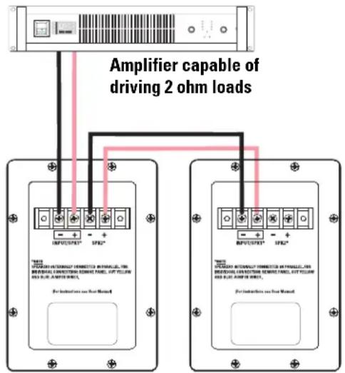
text_image
Amplifier capable of driving 2 ohm loads For instructions on Our Manual For instructions on Our ManualIndividual Transducer Connection (requires modification)
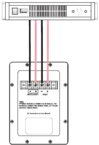
The transducers are wired in parallel inside the enclosure. If individual transducer connection is required, remove the terminal cup and remove the yellow and the blue jumper wires that are connected between the SPK1 and SPK2 terminals. Replace the terminal cup and mark the enclosure with a note of the modification.
Individual Transducer Connection Example:

CAUTION! Requires removal of terminal cup and removing both the yellow and the blue jumper wires that connect the SPK1 and SPK2 terminals.
text_image
INTUUSIP30® SP42® "INTUUSIP30" INTUUSIP30 CONNECTED INTUUSIP30 IN VERIAND ENERRED IN REMOLED POWER, LET YELLOW AND BHAZ AMOUNTED. Pre-Inteakable use for MetalLF-3215 Specifications (subject to change without notice)
Frequency Range: 32 - 1500 Hertz (-6dB)
28 - 3300 Hertz useable range (-10dB)
Nominal Coverage: 100° horizontal X 55° vertical at 600 Hertz
Maximum Output:
132.5 dB SPL calculated peak, 1 meter, half space, at rated rms power with 6 dB crest factor pink noise input, 25 - 250 Hertz. 126.5 dBA SPL calculated maximum continuous, 1 meter. The dBA scale is typically used to identify sound sources which can cause permanent hearing loss.
Impedance: 4 ohms nominal
4.1 ohms minimum, 180 Hertz
55 ohms maximum, 21 Hertz
Maximum Input Power:
600 watts rms (8 hours of 6 dB crest factor pink noise, 40 - 400 Hertz)
750 watts rms (2 hours of 6 dB crest factor pink noise, 40 - 400 Hertz)
Recommended amplifier power capability- 1200 watts rms maximum into 4 ohms (per LF-3215)
Sensitivity: 98.5 dB half space, 97.5 dB full space, 35 - 1000 Hertz, 1 watt, 1 meter
Recommended Processing:
Subsonic filter below 30 Hertz, >18 dB per octave, maximum recommended crossover frequency is 1000 Hertz. QSC DSP configurations are available at www.qscaudio.com. Parameters for alternative processing hardware are available upon request.
Connectors:
Barrier strip screw terminals accept up to #10 AWG stranded wire. Four terminals: (two INPUT and two PARALLEL OUT). Transducers are internally wired in parallel. For independent transducer connection, remove blue jumper wire and yellow jumper wire on internal-side of terminal cup and mark enclosure accordingly.
Transducers:
Two 15" (381mm) high efficiency low frequency transducers featuring vented 3" (76mm) copper voice coils on Kapton® formers. High excursion/low distortion design, with extremely high power handling, and low thermal and port compression.
Enclosure:
Quasi B4 alignment, ported enclosure with fully flared ports, low turbulence symmetrical port design, tuned to 36 Hertz, constructed of medium density fibreboard and heavily braced. Features vandal resistant woofer mounting bolts.
Size: 30" wide X 35" high X 20" deep (762 mm X 889 mm X 508 mm)
Weight: 195 lbs. shipping, 172 lbs. net (88/78 kg.)
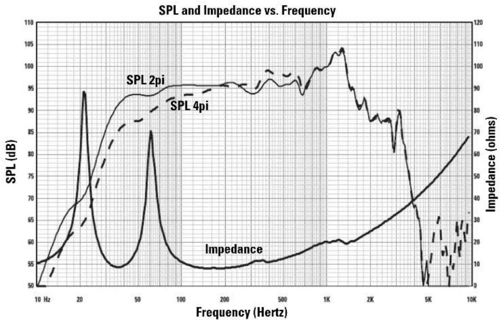
line
| Frequency (Hertz) | SPL (dB) | Impedance (ohms) | | ----------------- | -------- | ---------------- | | 10 | 50 | 0 | | 20 | 95 | 30 | | 50 | 85 | 60 | | 100 | 55 | 70 | | 200 | 55 | 75 | | 500 | 60 | 80 | | 1K | 105 | 90 | | 2K | 90 | 85 | | 5K | 30 | 40 | | 10K | 70 | 60 |Warranty (USA only; other countries, see your dealer or distributor)
Disclaimer
QSC Audio Products, Inc. is not liable for any damage to amplifiers, or any other equipment that is caused by negligence or improper installation and/or use of this loudspeaker product.
QSC Audio Products 3 Year Limited Warranty
QSC Audio Products, Inc. ("QSC") guarantees its products to be free from defective material and / or workmanship for a period of three (3) years from date of sale, and will replace defective parts and repair malfunctioning products under this warranty when the defect occurs under normal installation and use - provided the unit is returned to our factory or one of our authorized service stations via pre-paid transportation with a copy of proof of purchase (i.e., sales receipt). This warranty provides that the examination of the return product must indicate, in our judgment, a manufacturing defect. This warranty does not extend to any product which has been subjected to misuse, neglect, accident, improper installation, or where the date code has been removed or defaced. QSC shall not be liable for incidental and/or consequential damages. This warranty gives you specific legal rights. This limited warranty is freely transferable during the term of the warranty period.
Customer may have additional rights, which vary from state to state.
In the event that this product was manufactured for export and sale outside of the United States or its territories, then this limited warranty shall not apply. Removal of the serial number on this product, or purchase of this product from an unauthorized dealer, will void this limited warranty. Periodically, this warranty is updated. To obtain the most recent version of QSC's warranty statement, please visit www.qscaudio.com. Contact us at 800-854-4079 or visit our website at www.qscaudio.com.
Contacting QSC Audio Products
Mailing address: QSC Audio Products, Inc.
1675 MacArthur Boulevard
Costa Mesa, CA 92626-1468 USA
Telephone Numbers:
Main Number (714) 754-6175
Sales & Marketing (714) 957-7100 or toll free (USA only) (800) 854-4079
Customer Service(714) 957-7150 or toll free (USA only) (800) 772-2834
Facsimile Numbers:
Sales & Marketing Fax(714) 754-6174
Customer Service Fax(714) 754-6173
World Wide Web:www.qscaudio.com
E-mail:info@qscaudio.com
service@qscaudio.com
QSC™
natural_image
Line drawing of a two-tiered speaker box with circular cutouts and a small inset component (no text or symbols)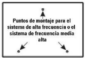
text_image
30" (762mm)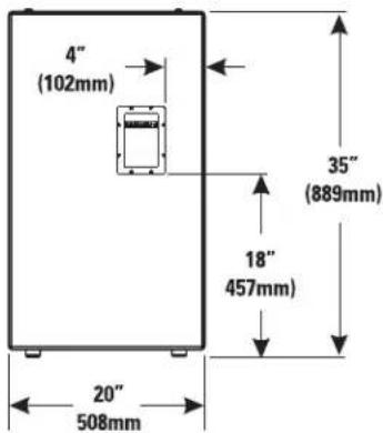
text_image
4" (102mm) 35" (889mm) 18" 457mm) 20" 508mmTD-000173-00 rev. C
© Derechos de autor 2004, QSC Audio Products, Inc.
service@qscaudio.com
natural_image
Technical line drawing of a two-tiered speaker chamber with circular cutouts and a small inset component (no text or symbols)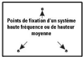
text_image
30" (762mm)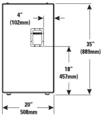
text_image
4" (102mm) 35" (889mm) 18" 457mm) 20" 508mmBranchements
Branchement normal
Adresse postale : QSC Audio Products, Inc.
1675 MacArthur Boulevard
service@qscaudio.com

natural_image
Technical line drawing of a two-tiered speaker chamber with circular cutouts and a small inset component (no text or symbols)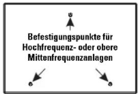
text_image
30" (762mm)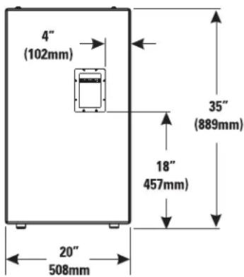
text_image
4" (102mm) 35" (889mm) 18" 457mm) 20" 508mmVerbindungen
Normaler Anschluss
text_image
INFLUFP3* SP2* "ALL" ITRALENTS AUTOMICS CONNECTED AUTOMICS, IN ITEMS, CONNECT TO SEMIPT PADS, LUT TOLER AND BIL AMOUNTES. For Interface to Our Manual:service@qscaudio.com

QSC Audio Products, Inc. 1675 MacArthur Boulevard Costa Mesa, California 92626 USA
natural_image
Line drawing of a two-tiered speaker chamber with circular cutouts and a small inset component (no text or symbols)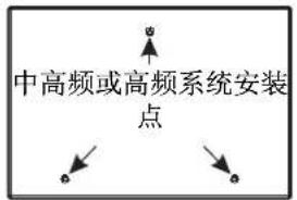
text_image
30" (762mm)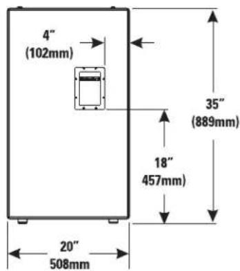
text_image
4" (102mm) 35" (889mm) 18" 457mm) 20" 508mm连接
正常连接
text_image
INFRSF201 SPF2 "ALL" STRAWING ITEMS OF FRESHING ITEMS FOR ALL ITEMS FROM THE SHEET NAME, LET TOLER AND BUY ITEMS For instructions for Manual
service@qscaudio.com

QSC Audio Products, Inc. 1675 MacArthur Boulevard Costa Mesa, California 92626 USA