
RAREC2A - Thermostat Café - Free user manual and instructions
Find the device manual for free RAREC2A Café in PDF.

| Product Type | Wall-mounted thermostat for RV air conditioning and heating |
| Brand | Café (GE Appliances) |
| Model | RAREC2A |
| Power Supply | 12 VDC (range 10.5 V – 15.5 V) |
| Dimensions (approx.) | 120 mm × 80 mm × 25 mm |
| Weight (approx.) | 150 g |
| Operating Temperature Range | Cool: 15°C–46°C; Heat pump: -4°C–30°C; Furnace: -4°C–30°C |
| Setpoint Range | Cool: 15°C–30°C; Heat pump: 5°C–30°C; Furnace: 5°C–30°C |
| Display | Backlit LCD screen, temperature in °F/°C |
| Operating Modes | Off, Fan Only, Cool, Heat Pump Only, Heat Pump + Furnace, Furnace Only |
| Fan Speeds | Auto, On |
| Connections | 5 direct-wire connections (R, Y, B, etc.); RV-C compatible |
| DIP Configuration | 6 switches for zone, product type, options |
| Built-in Sensors | Ambient temperature sensor, indoor/outdoor coil sensor (model dependent) |
| Protection | Low voltage detection, freeze prevention, automatic defrost, heat pump lockout |
| Maintenance | Clean filter and vents regularly; turn off power before any service |
| Safety | Power must be turned off before installation; max voltage 12 VDC; comply with local codes |
| Warranty | 1 year, full thermostat replacement |
Frequently Asked Questions - RAREC2A Café
User questions about RAREC2A Café
0 question about this device. Answer the ones you know or ask your own.
Ask a new question about this device
Download the instructions for your Thermostat in PDF format for free! Find your manual RAREC2A - Café and take your electronic device back in hand. On this page are published all the documents necessary for the use of your device. RAREC2A by Café.
USER MANUAL RAREC2A Café
OWNER'S MANUAL & INSTALLATION INSTRUCTIONS
RARWT__ (Single Zone Smart T.Stat)
RARMC__ (Standard Ceiling Control)
RAREC3A (Standard Ceiling Control)
RAREC2A (Direct Wire or Smart T.Stat)
RAREC1A (RV-C or Smart T.Stat Control)
Important Safety Information ....3
Installation Instructions 4
Controls....8
Controls and Operating Functions ..... 9
On Board Diagnostics .... 11
Fault Codes....12
Wiring Diagram....13
Testing the Thermostat....14
Troubleshooting....16
Limited Warranty 17
Consumer Support 18
Write the model and serial numbers here:
Model # ____
Serial # ____
You can find them on a label on the thermostat.
THANK YOU FOR MAKING GE APPLIANCES A PART OF YOUR RV.
Whether you grew up with GE Appliances, or this is your first, we're happy to have you in the family.
We take pride in the craftsmanship, innovation and design that goes into every GE Appliances product, and we think you will too. Among other things, registration of your appliance ensures that we can deliver important product information and warranty details when you need them.

GE APPLIANCES
IMPORTANT SAFETY INFORMATION
READ ALL INSTRUCTIONS BEFORE USING THE APPLIANCE
WARNING
FIRE AND SHOCK HAZARD
■ Always turn off power at the main power supply before installing, cleaning or removing the thermostat.
■ Do not use on voltages over 12 VDC. Higher voltages will damage the thermostat and could cause shock or fire hazards.
■ All wiring must conform to local and national electrical and building codes.
■ Use this thermostat only as described in this manual.
Specifications
Electrical Rating:
12 VDC (Operating Range from 10.5 VDC - 15.5 VDC)
| Operating Ranges Setpoint Ranges | ||||
| Cooling 60°F | -115°F 15°C | -46°C 60°F | -85°F 15°C | -30°C |
| Heat-Pump | 25°F-85°F -4°C | -30°C 40°F | -85°F 5°C | -30°C |
| Furnace See Owner's Manual | 40°F-85°F 5°C-30°C | |||
Wall Thermostat Terminations:
0V (GND), Signal (COMMS), +12VDC
Recommended Wire Sizes:
| CIRCUIT WIRE GAUGE | Copper Wire Type | |
| 115 VAC Control Power | 12awg SOLID | |
| 12 VDC Control Power | 14awg~18awg | STRANDED |
| 12 VDC Thermostat 18a | wg~22awg SOLID | |
| COMMUNICATION CONNECTIONS | ||||||
| Ceiling Control | GEA Smart Wall Thermostat (RARWT_) | 5 Wire Direct Connect | RV-C Network | RV-C Room Sensor Compatible (RARES1_) | Aux. Furnace Connection | Auto Gen Start Connection |
| RARMC2A_ | X | X | ||||
| RAREC3A_ | X | X | ||||
| RAREC2A_ | X | X | X | X | ||
| RAREC1A_ | X | X | X | X | X | |
WARNING
ELECTRICAL SHOCK HAZARD
Turn off power by removing the fuse or switching the appropriate circuit breaker to the OFF position before removing the existing thermostat.
Package Contents
■ Thermostat on cover
■ Thermostat base
■ Screws
Tools Required
■ Drill with 1/8" bit
■ Ballpoint Pen
■ Screwdriver
To Remove Existing Thermostat
- Turn off power to the heating and cooling system by removing the fuse or switching off the appropriate circuit breaker (115 VAC and 12VDC)
- Remove cover of old thermostat. This should expose the wires.
- Label the existing wires with wire labels before removing wires.
- After labeling wires, remove wires from terminal block.
- Remove existing thermostat base from wall.
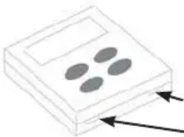
natural_image
Simple line drawing of a device with four oval cutouts and two arrows pointing outward (no text or symbols)Apply screwdriver or ballpoint pen "here to open thermostat
To Install Thermostat and Main Control
IMPORTANT: Thermostat installation must conform to local and national building and electrical codes and ordinances.
NOTE: It is recommended to mount the thermostat between
4 and 5 feet above the floor. It is not recommended to mount the thermostat on an outside wall, in direct sunlight, behind a door, or in an area affected by a vent or duct.
- Turn off power to the heating and cooling system by removing the fuse or switching off the appropriate circuit breaker. (115 VAC and 12VDC).
- Mount main control box to the mounting template using four screws.
- Remove three screws from the main control box, allowing the bottom section to hinge open. Control board is now visible and accessible.
- Route the 115 VAC power cord through the strain relief of the control box. Tighten the strain relief, making sure not to damage the wires.
- Using wire connectors, connect line to black, neutral to white, and ground to green.
- Using electrical tape or wire nuts, secure the connectors to prevent any potential movement due to vehicle vibration.
-
Route the 6 pin connector through the opening of the hemmed strain relief of the control box. Mate 6 pin connector to the control box's wire harness.
-
Mate the thermistors to the corresponding interconnects on the main board. These will be bundled with the 6-pin connector in the rooftop unit. For ARC models, one connection will need to be made (indoor coil sensor). For ARH models, an additional connection will need to be made (ambient/outdoor coil sensors).
- Using wire connectors, connect 2 furnace wires (blue and optional), 2 auto gen start wires (yellow, optional, and only for RAREC1A and RAREC2A controls), 3 thermostat wires (red, yellow, and black), and two 12 VDC battery wires (red and black).
- Rotate lower section of control box upwards making sure not to crush any wires. Drive three screws, securing he control box closed. The main control install is now complete.
- Remove the cover from the base by undoing the two plastic snaps on the bottom of the base. A small screwdriver or ballpoint pen can be used to gently depress one snap at a time (reference the figure on page 5).
- Put thermostat base against the wall where you plan to mount it. Make sure wires will feed through the wire opening in the base of the thermostat.
- With the base level, mark the placement of themounting holes.
14 Ensure no other wires are affected by the drilling of 1/8" holes. - Using a 1/8" drill bit, drill pilot holes in the locations you have marked for the wood screws.
- Align thermostat base with mounting holes and feed the control wires through the wire opening.
To Install Thermostat and Main Control (continued)
- Use supplied screws to mount thermostat base to wall.
- Insert stripped, labeled wires in matching wire terminals and tighten terminal screws once properly aligned. See the “Wiring Diagrams” section of this manual.
CAUTION
Make sure exposed portion of wires does not touch other wires.
- Gently tug each wire to be sure of proper connection. Verfiy that each wire is connected to the proper terminal.
- For Heat Pump models (ARH13AHC_ & ARH15AAC_), flip switch #1 to the "ON" position (see figure on page 12). Additionally, if your unit will not be connected to a furnace, furnace mode can be disabled by toggling switch #4 to the "ON" position (see figure on page 12).
- Reattach the thermostat cover by aligning the cover and snapping the bottom in place.
- Turn on power to the system at the main service panel.
- Test thermostat operation as described in the "Testing the thermostat" section.
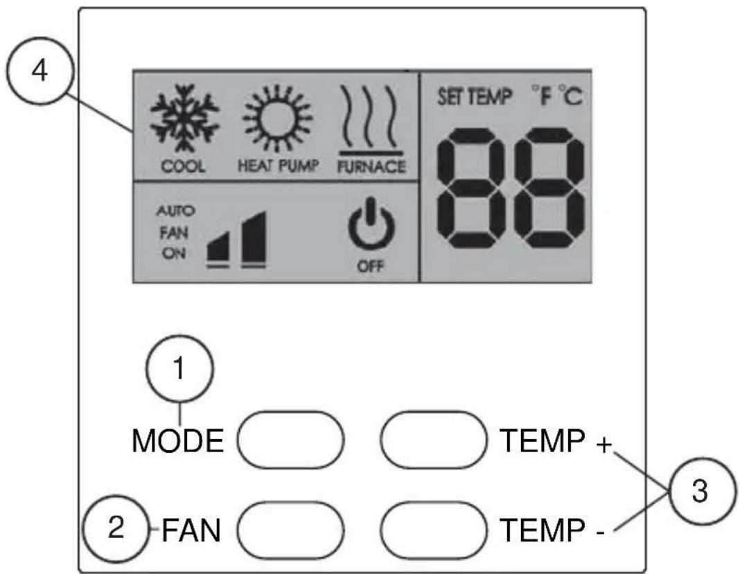
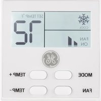
1. Mode Button
Use this button to toggle between the following modes.
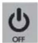
OFF – The air conditioner and RV's furnace will not operate.
FAN ONLY – The fan will operate to circulate air.
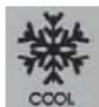
COOL – The air conditioner will operate to lower the RV temperature
NOTE: only use HEAT-PUMP modes with rooftop models ARH13AHC_ or ARH15AAC_.
Enable Heat-Pump modes by turning ON DIP Switch #1 located on the back side of the thermostat. (see Wiring Diagram)
Controls and Operating Functions (RARWT\_)
1. Mode Button (continued)
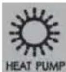
HEAT PUMP ONLY – the unit will operate the heat-pump to raise the RV temperature.
NOTE: if the outdoor ambient drops below 25^ F (-4°C), the heat-pump will be disabled.
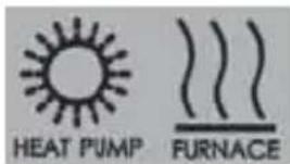
HEAT PUMP + FURNACE – the unit will first operate the heat-pump to conserve propane. If the RV temperature drifts further than 3^ F from the setpoint, then the RV's furnace will be turned ON.
NOTE: the furnace will automatically turn ON, if the outdoor temperature drops below 25^ F ( -4^ C) or if the Heat-Pump begins a defrost.
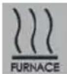
FURNACE ONLY – the RV's furnace will operate to raise the RV temperature. This mode can be disabled by toggling switch #4 on the thermostat to the "ON" position.
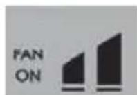
2. Fan Button
Use this button to toggle between fan speeds and fan modes.
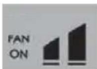
FAN ON – the fan will run even when the set point has been reached.
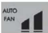
AUTO FAN – the fan will turn off once the set point has been reached.
3. Temperature Selection Buttons
Use these buttons to raise and lower the set point.

To change between Fahrenheit (°F) and Celsius (°C), hold both “TEMP +” and “TEMP -” at the same time for 2 seconds.
Control and Operating Functions (RAREC1A)
Zone selection...
| Switch #1 | Switch #2 | Switch #3 | ||
| ON | OFF | OFF | Zone 1 | (1) |
| OFF | ON | OFF | Zone 2 | (2) |
| OFF | OFF | ON | Zone 3 | (3) |
| ON | OFF | ON | Zone 4 | (1×3) |
| OFF | ON | ON | Zone 5 | (2×3) |
| ON | ON | ON | Zone 6 | (1×2+5) |
| ON | ON | OFF | Zone 7 | |
| OFF | OFF | OFF | Zone 8 | |
| DIP SWITCH | RV-CPRODUCT TYPE | DSA[FOR ALL ZONES] | Dynamic Address Range | ||
| #4 | #5 | #6 | |||
| OFF | OFF | Either | RV-C AIR CONDITIONER (& HP) | 103 (6.7%) | 1X2 - 207(CON - OFF) |
| ON | OFF | Either | RV-C AIR CONDITIONER (& HP)and RV-C FURNACE | 103 (6.7%) | |
| OFF | ON | Either | RV-C VIRTUAL THERMOSTATwith A/C Status (& HP) | 88 (5.8%) | |
| 103 (6.7%) | |||||
| ON | ON | Either | RV-C VIRTUAL THERMOSTATwith A/C Status (& HP)with FURNACE Status | 88 (5.8%) | |
| 103 (6.7%) | |||||
| 94 (5.8%) | |||||
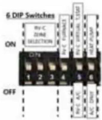
If Switch #5 is ON (RV-C Virtual T.Stat Method), an RARES1A room sensor kit will be required.
Control and Operating Functions (RAREC2A)
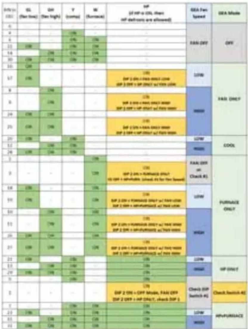
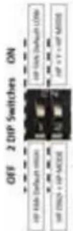
Switch #1 specifies default fan speed in HP Mode if GL or GH is not specified.
Switch #2 specifies if a "Y" signal is required for HP Mode.
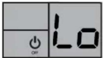
Low Voltage Detection:
If the 12VDC drops below 10.5V, the thermostat will switch to “OFF” mode and flash “Lo”.
When voltage exceeds 10.5V, the display will show a constant “Lo” and remain in “OFF” mode until a different mode is reselected by the user.
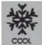
A/C Freeze-Up Prevention:
In COOL mode, a flashing snowflake icon indicates that the indoor coil is near freezing, and
that the compressor was turned off.
Recommend increasing airflow by cleaning the filter and opening vents.
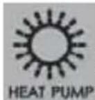
Heat-Pump Auto-Defrost:
In HEAT-PUMP modes, a flashing HEAT-PUMP icon indicates that the unit is performing an auto-
In HEAT-PUMP+FURNACE mode, while auto-defrosting, the unit will use the furnace.
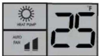
Heat-Pump Lockout:
In HEAT-PUMP ONLY mode, a flashing HEAT-PUMP icon AND 25 °F (-4°C) indicates that the outdoor
temperature dropped below 25 °F (-4°C) and the Heat-Pump is locked out.
Recommended when expecting temperatures below 25^ F ( -4^ C) to use HEAT-PUMP+FURNACE or FURANCE ONLY mode.
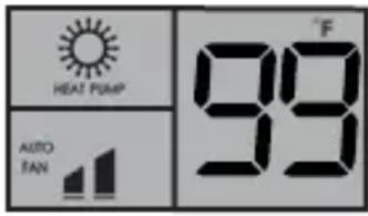
Heat-Pump Over Temperature:
In HEAT-PUMP modes, a flashing HEAT-PUMP icon AND 99°F (99°C)
indicates that the indoor coil reached
a temperature above 135^ F ( 58^ C) and the compressor was shut off.
Recommended to increase airflow by cleaning the filter and opening vents.
Fault Codes (RARWT_)
| Fault Codes | |||
| Display Code | Affected Sensor | Potential Cause | |
| All Models | F1 Indoor Coil Unplugged Sensor or Temp less than -22°F (-30°C) | ||
| F2 Indoor Coil Shorted wires or temp greater than 149°F (65°C) | |||
| Heat Pump Models | F3 Outdoor Coil Unplugged Sensor or Temp less than -22°F (-30°C) | ||
| F4 Outdoor Coil Shorted wires or temp greater than 149°F (65°C) | |||
| Dip Switch 1 ON | F5 Outdoor Temp Unplugged sensor, or Dip Switch 1 set to “ON” for AC only model. Temp less than -22°F (-30°C) | ||
| F6 Outdoor Temp Shorted wires or temp greater than 149°F (65°C) | |||
| All Models | F7 Thermostat Room Sensor | Unplugged Sensor or Temp less than -22°F (-30°C) | |
| F8 Thermostat Room Sensor | Shorted wires or temp greater than 149°F (65°C) | ||
| F9 -- FC | Signal Wire Thermostat signal wire is unplugged or shorted (Not communicating to the main control) | ||
Table 1: terminals for three wires 1-stage heat / 1-stage cool system.
flowchart
graph TD
    A["Smart Wall Thermostat (RARWT__)"] --> B["ON"]
    B --> C["4 DIP Switches"]
    C --> D["OFF"]
    D --> E["HEAT-PUMP"]
    E --> F["N/A"]
    E --> G["N/A"]
    E --> H["NO FURNACE"]
    C --> I["GND"]
    C --> J["COMMS"]
    C --> K["+12V"]
    C --> L["A/C ONLY"]
    C --> M["N/A"]
    C --> N["FURNACE"]
    C --> O["T-Stat Signal yellow wire"]
    C --> P["+12V to T-Stat red/white wire"]
    C --> Q["Blue / white"]
    C --> R["Auto Gen Relay"]
    C --> S["Furnace Relay"]
    C --> T["RAREC__ DIP Switches"]
    T --> U["VR-C Room Sensor (RARES1A)"]
    T --> V["RV-C Bus (12vdc Op@onal)"]
    T --> W["RV-C Bus (12vdc Op@onal)"]
    T --> X["RV-C Control Only (RAREC1A)"]
    T --> Y["Outdoor Coil Sensor"]
    T --> Z["Outdoor Ambient Sensor"]
    T --> AA["Indoor Coil Freeze Sensor"]
    T --> AB["Heat-Pump Only"]
    T --> AC["BRD"]
    T --> AD["WH"]
    T --> AE["PR"]
    T --> AF["RD"]
    T --> AG["Blue"]
    T --> AH["Yellow / white"]
    T --> AI["Blue / white"]
    T --> AJ["Blue / white"]
    T --> AK["Blue / white"]
    T --> AL["Blue / white"]
    T --> AM["Blue / white"]
    T --> AN["Blue / white"]
    T --> AO["Blue / white"]
    T --> AP["Blue / white"]
    T --> AQ["Blue / white"]
    T --> AR["Blue / white"]
    T --> AS["Blue / white"]
    T --> AT["Blue / white"]
    T --> AU["Blue / white"]
    T --> AV["Blue / white"]
    T --> AW["Blue / white"]
    T --> AX["Blue / white"]
    T --> AY["Blue / white"]
    T --> AZ["Blue / white"]
    T --> BA["Blue / white"]
    T --> BB["Blue / white"]
    T --> BC["Blue / white"]
    T --> BD["Blue / white"]
    T --> BE["Blue / white"]
    T --> BF["Blue / white"]
    T --> BG["Blue / white"]
    T --> BH["Blue / white"]
    T --> BI["Blue / white"]
    T --> BJ["Blue / white"]
    T --> BK["Blue / white"]
    T --> BL["Blue / white"]
    T --> BM["Blue / white"]
    T --> BN["Blue / white"]
    T --> BO["Blue / white"]
    T --> BP["Blue / white"]
    T --> BQ["Blue / white"]
    T --> BR["Blue / white"]
    T --> BS["Blue / white"]
    T --> BT["Blue / white"]
    T --> BU["Blue / white"]
    T --> BV["Blue / white"]
    T --> BW["Blue / white"]
    T --> BX["Blue / white"]
    T --> BY["Blue / white"]
    T --> BZ["Blue / white"]
    T --> CA["Blue / white"]
    T --> CB["Blue / white"]
    T --> CC["Blue / white"]
    T --> CD["Blue / white"]
    T --> CE["Blue / white"]
    T --> CF["Blue / white"]
    T --> CG["Blue / white"]
    T --> CH["Blue / white"]
    T --> CI["Blue / white"]
    T --> CJ["Blue / white"]
    T --> CK["Blue / white"]
    T --> CL["Blue / white"]
    T --> CM["Blue / white"]
    T --> CN["Blue / white"]
    T --> CO["Blue / white"]
    T --> CP["Blue / white"]
    T --> CS["Blue / white"]
    T --> CT["Blue / white"]
    T --> CU["Blue / white"]
    T --> CV["Blue / white"]
    T --> CW["Blue / white"]
    T --> CX["Blue / white"]
    T --> CY["Blue / white"]
    T --> CZ["Blue / white"]
    T --> DA["Blue / white"]
    T --> DB["Blue / white"]
    T --> DC["Blue / white"]
    T --> DD["Blue / white"]
    T --> DE["Blue / white"]
    T --> DF["Blue / white"]
    T --> DG["Blue / white"]
    T --> DH["Blue / white"]
    T --> DI["Blue / white"]
    T --> DJ["Blue / white"]
    T --> DK["Blue / white"]
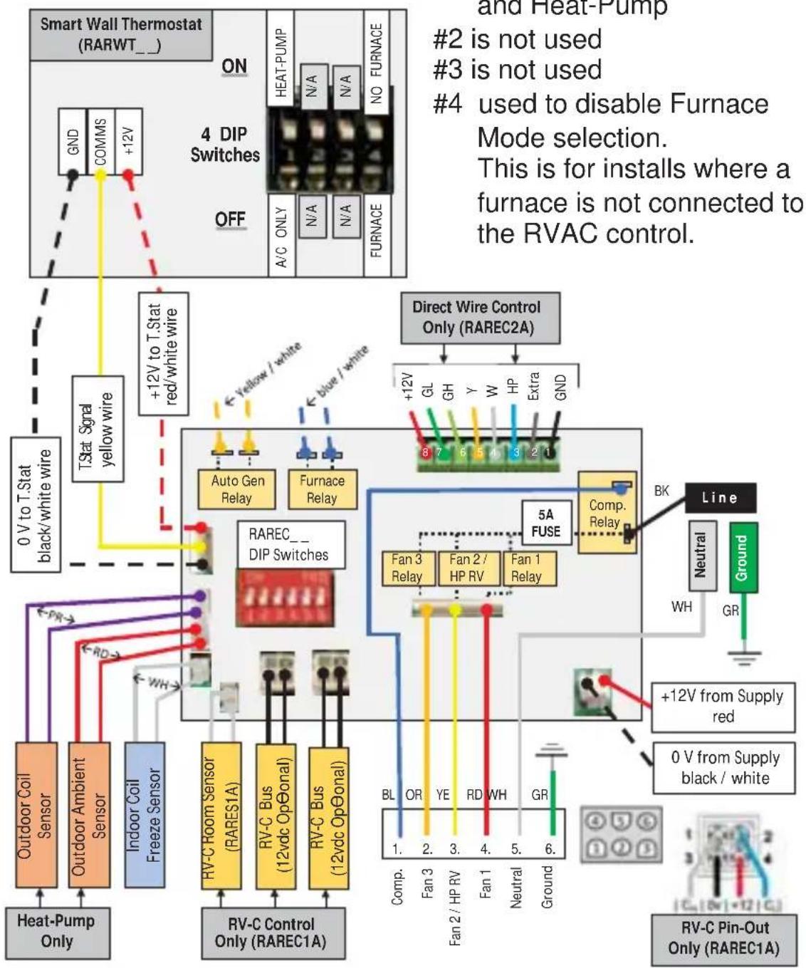
RARWT__ DIP Switches
1 select between Cool Only and Heat-Pump
2 is not used
3 is not used
4 used to disable Furnace Mode selection.
This is for installs where a furnace is not connected to the RVAC control.
Once the thermostat is installed, it should be tested for functionality.
NOTE: Before testing the thermostat, press the Fan Auto/On button until the display shows the Auto position.
Fan Test
- Toggle Mode button to Fan ON position.
- Fan turns on.
- Toggle between low and high fan speeds with the FAN button.
- Speed should adjust accordingly
Cool Test
- Toggle Mode button until Cool mode is on. Cool mode screen is displayed.
- Adjust set temperature so it is 5 degrees below room temperature.
- Air conditioning should come on within a few seconds.
- Adjust the set temperature so it is 2 degrees above the room temperature and the A/C should turn off. Note: There is a 3 minute time delay and a 3 minute minimum run time for the compressor when it turns on/off.
Heat Pump Test (ARH models only)
- Toggle Mode button until Heat Pump mode is on. Heat Pump screen is displayed.
- Adjust set temperature so it is 5 degrees above room temperature.
- Heating should come on within a few seconds.
- Adjust the set temperature so it is 2 degrees below the room temperature and the Heat Pump should turn off.
NOTE: There is a 3 minute time delay and a 3 minute minimum run time for the compressor when it turns on/off.
Furnace Test
- Toggle mode button until furnace mode is active. Furnace mode screen is displayed.
- Adjust set temperature so it is 5 degrees above room temperature. Within a few seconds, the furnace should initiate its startup procedure.
- Adjust the set temperature so it is 2 degrees below the room temperature and the heat should turn off. Note: Depending on the model of furnace used, there may be a delay in engaging and disengaging the furnace.
Troubleshooting Tips
| Problem Solution | |
| Display is blank Check for | 12VDC; display is blank when 12V is not present. |
| All thermostat buttons are non-responsive | Verify that the 12VDC is present; the unit will not operate when the voltage is below 10.5V. |
| Fan and Compressor will not turn ON | Verify that 115VAC is present. |
| Fan does not turn ON, but the Compressor does turn ON | WITH POWER REMOVED, verify that nothing is obstructing the fan blade, that it spins freely.Check the 5 amp Fuse on the board |
| Fan runs continuously Check Fan Mode. If set to FAN ON, the fan will run continuously. | |
| Room Temperature does not match Setpoint when the unit shuts off | Verify proper installation per installation instructions (pg. 5 ... not on exterior wall or in direct sunlight... ...in an area affected by a vent or duct...) |
| Compressor does not turn ON immediately when changing Modes or Setpoint | This is normal, there is a 3 minute OFF timer preventing the compressor from being turned OFF and right back ON. |
| Fan does not turn ON immediately when changing Modes or Setpoint | In Heat-Pump mode, if Auto Fan is selected, the fan will not turn ON until the compressor turns ON after the 3 minute OFF timer. |
| F5 Flashes on the Wall Thermostat | With a Cool Only model, check that DIP Switch #1 on the back side of the wall thermostat is turned OFF.(see Wiring Diagram)With a Heat-Pump model, check to see if the outdoor temperature sensor is unplugged or damaged. |
Thermostat Limited Warranty
Staple your receipt here.
Proof of the original purchase date is needed to validate the warranty.
For The Period Of: GE Appliances Will Replace:
Two Years Full Replacement of the thermostat which fails
From the date of the due to a defect in materials or workmanship.
original purchase
What GE Appliances Will Not Cover:
■ Service trips to your location.
- Improper installation. If you have an installation problem, contact your installer. You are responsible for providing adequate electrical connections to the product.
■ Failure of the product resulting from modifications to the product or due to unreasonable use, including failure to provide reasonable and necessary maintenance.
In commercial locations, labor necessary to move the unit, after it has been initially installed, to a location where it is accessible for service by an individual technician; or, if the instructions included in this manual have been disregarded.
■ Replacement of location fuses or the resetting of circuit breakers.
■ Damage to the product caused by improper power supply voltage, accident, fire, floods or acts of God.
■ Incidental or consequential damage caused by possible defects with this thermostat.
EXCLUSION OF IMPLIED WARRANTIES—Your sole and exclusive remedy is product exchange as provided in this Limited Warranty. Any implied warranties, including the implied warranties of merchantability or fitness for a particular purpose, are limited to one year or the shortest period allowed by law.
This limited warranty is extended to the original purchaser and any succeeding owner for products purchased for use within the USA and Canada. In Alaska, the limited warranty excludes the cost of shipping or service calls to your site.
Some states or provinces do not allow the exclusion or limitation of incidental or consequential damages. This limited warranty gives you specific legal rights, and you may also have other rights which vary from state to state or province to province. To know what your legal rights are, consult your local, state or provincial consumer affairs office or your state's Attorney General.
Warrantor: GE Appliance, a Haier company. Louisville, KY 40225
Consumer Support
GE Appliances Website
Have a question or need assistance with your appliance? Try the GE Appliances Website 24 hours a day, any day of the year! You can also shop for more great GE Appliances products and take advantage of all our on-line support services designed for your convenience. In the US: GEAppliances.com
Register Your Appliance
Register your new appliance on-line at your convenience! Timely product registration will allow for enhanced communication and prompt service under the terms of your warranty, should the need arise. You may also mail in the pre-printed registration card included in the packing material. In the US: GEAppliances.com/register
Schedule Service
Call 1-877-540-7837 during normal business hours.
Extended Warranties
Purchase a GE Appliances extended warranty and learn about special discounts that are available while your warranty is still in effect. You can purchase it on-line anytime. GE Appliances Services will still be there after your warranty expires. In the US: GEAppliances.com/extended-warranty or call 800.626.2224 during normal business hours.
Remote Connectivity
For assistance with wireless network connectivity (for models with remote enable), visit our website at GEAppliances.com/connected-home-smart-appliances or call 800.220.6899 in the US.
Parts and Accessories
Individuals qualified to service their own appliances can have parts or accessories sent directly to their homes (VISA, MasterCard and Discover cards are accepted). Order on-line today 24 hours every day. In the US: GEApplianceparts.com or by phone at 877.959.8688 during normal business hours.
Instructions contained in this manual cover procedures to be performed by any user. Other servicing generally should be referred to qualified service personnel. Caution must be exercised, since improper servicing may cause unsafe operation.
Contact Us
If you are not satisfied with the service you receive from GE Appliances, contact us on our Website with all the details including your phone number, or write to:
General Manager, Customer Relations | GE Appliances, Appliance Park | Louisville, KY 40225 GEAppliances.com/contact
0 V (GND), Signal (COMMS), +12 VCC
natural_image
Simple line drawing of a device with four oval cutouts and two arrows pointing outward (no text or symbols)| Date in 2001 | SL (New time) | CM (New high) | Y (comp) | W (Sustainable) | HP (all HP is CTR, then self deliver any allowed) | USA Fast Speed | USA Mode |
| 4 | RMS DFF | DFF | |||||
| 5 | 198 | ||||||
| 6 | 176 | 176 | |||||
| 11 | 200 | 176 | 176 | ||||
| 14 | 200 | 176 | 176 | ||||
| 30 | 200 | 200 | 176 | 176 | |||
| 10 | 200 | LFP | RMS DFF | ||||
| 17 | 200 | 176DP 2 GPs + PaaS (GMT) (GMP 3 GPP + GP (GMT) + FMS (GMP) | MMS | ||||
| 8 | 200 | ||||||
| 9 | 200 | 176DP 2 GPs + PaaS (GMT) (GMP 3 GPP + GP (GMT) + FMS (GMP) | |||||
| 24 | 200 | 200 | |||||
| 25 | 200 | 200 | 176DP 2 GPs + PaaS (GMT) (GMP 3 GPP + GP (GMT) + FMS (GMP) | ||||
| 29 | 200 | 176 | LFP | CDOX | |||
| 32 | 200 | 176 | |||||
| 24 | 200 | 200 | 176 | MMS | |||
| 3 | 176 | PUMBASE ONLY | |||||
| 3 | 176 | 176DP 2 GPs + PUMBASE (GMT) (GMP + PUMBASE (GMT) + FMS (GMP) for Tne Speed) | RMS DFF on Check #1. | ||||
| 14 | 200 | 176 | LFP | ||||
| 19 | 200 | 176 | 176DP 2 GPs + PUMBASE (GMT) (GMP + PUMBASE (GMT) + FMS (GMP) for Tne Speed) | ||||
| 24 | 200 | 176 | MMS | ||||
| 31 | 200 | 176 | 176DP 2 GPs + PUMBASE (GMT) (GMP + PUMBASE (GMT) + FMS (GMP) for Tne Speed) | ||||
| 29 | 200 | 200 | 176 | ||||
| 25 | 200 | 200 | 176 | 176DP 2 GPs + PUMBASE (GMT) (GMP + PUMBASE (GMT) + FMS (GMP) for Tne Speed) | |||
| 21 | 200 | 176 | 176 | LFP | WP Only | ||
| 23 | 176 | 176 | 176 | MMS | |||
| 29 | 200 | 200 | 176 | 176 | |||
| 3 | 176 | 176 | Check (GP switch #1) | Check switch #2 | |||
| 3 | 176DP 2 GPs + GP (GMT), FMS (GMP DP 2 GPP + GP (GMT), check (GP #1) | ||||||
| 3 | 176 | 176 | 176 | ||||
| 23 | 200 | 176 | 176 | 176 | LFP | HIFURSACE | |
| 31 | 176 | 176 | 176 | 176 | MMS | ||
| 31 | 200 | 200 | 176 | 176 | 176 |

flowchart
Smart Wall Thermostat (RARWT_) wiring diagram showing connections to 4 DIP switches, RAREC2A relay, and supply lines with color-coded wires and terminal blocks.Garant : GE Appliances, Louisville, KY 40225
,QVWUXFFLRQHVGH, QVWDODFLyQ
%RPEDGH&DORU SRU(QFLPD GHOD 7HPSHUDWXUD
GEAppliances.com/contact
- OWNER'S MANUAL & INSTALLATION INSTRUCTIONS
- THANK YOU FOR MAKING GE APPLIANCES A PART OF YOUR RV.
- IMPORTANT SAFETY INFORMATION
- READ ALL INSTRUCTIONS BEFORE USING THE APPLIANCE
- WARNING
- FIRE AND SHOCK HAZARD
- Specifications
- ELECTRICAL SHOCK HAZARD
- Package Contents
- Tools Required
- To Remove Existing Thermostat
- To Install Thermostat and Main Control
- IMPORTANT: Thermostat installation must conform to local and national building and electrical codes and ordinances.
- To Install Thermostat and Main Control (continued)
- CAUTION
- Mode Button
- Controls and Operating Functions (RARWT\_)
- Mode Button (continued)
- Fan Button
- Temperature Selection Buttons
- Control and Operating Functions (RAREC1A)
- Control and Operating Functions (RAREC2A)
- Low Voltage Detection:
- A/C Freeze-Up Prevention:
- Heat-Pump Auto-Defrost:
- Heat-Pump Lockout:
- Heat-Pump Over Temperature:
- select between Cool Only and Heat-Pump
- is not used
- is not used
- used to disable Furnace Mode selection.
- Fan Test
- Cool Test
- Heat Pump Test (ARH models only)
- Furnace Test
- Troubleshooting Tips
- Thermostat Limited Warranty
- For The Period Of: GE Appliances Will Replace:
- What GE Appliances Will Not Cover:
- Consumer Support
- GE Appliances Website
- Register Your Appliance
- Schedule Service
- Extended Warranties
- Remote Connectivity
- Parts and Accessories
- Contact Us
- ,QVWUXFFLRQHVGH, QVWDODFLyQ
- %RPEDGH&DORU SRU(QFLPD GHOD 7HPSHUDWXUD
Brand : Café
Model : RAREC2A
Category : Thermostat