
WHAW-241IN - Air Conditioning WHIRLPOOL - Free user manual and instructions
Find the device manual for free WHAW-241IN WHIRLPOOL in PDF.

| Brand | Whirlpool |
| Model | WHAW-241IN |
| Product type | Air conditioning |
| Category | Window / wall air conditioner |
| Cooling capacity | 24 000 BTU |
| Dimensions | Interior frame height 17.13\" (435 mm), Interior frame width 25.59\" (650 mm) |
| Weight | Not specified (estimated ~35 kg) |
| Power supply | 208/230 V, 60 Hz, 15-20 A depending on model |
| Recommended fuse | Circuit breaker or time-delay fuse 20 A (for 24K) |
| Refrigerant | R32 (flammable, environmentally friendly) |
| Operating modes | Cool (cooling), Dry (dehumidification), Fan (ventilation), Auto |
| Special functions | ECO, Sleep, Timer, Swing, Mute, Filter reminder |
| Fan speeds | Auto, Low, Medium, High |
| Temperature range | Indoor 61-88 °F (16-31 °C); Outdoor 64-109 °F (18-43 °C) |
| Minimum room area | Greater than 25 m² (269 ft²) for R32 |
| Installation | Window (single/double hung) or through-wall |
| Required window width | 29.5\" to 41\" (750-1040 mm) |
| Tilt | Approximately 3° outward for drainage |
| Remote control | Yes, AAA batteries (included) |
| Display | LED with auto-off |
| Air filter | Washable, check monthly; reminder after 500 h |
| Maintenance | Clean filter, front panel, touch-up paint |
| Safety | Anti-tip protection (safety bracket), leakage current protection (cord with test/reset) |
| Warranty | 1 year limited (parts and labor) by XLS Products |
Frequently Asked Questions - WHAW-241IN WHIRLPOOL
User questions about WHAW-241IN WHIRLPOOL
0 question about this device. Answer the ones you know or ask your own.
Ask a new question about this device
Download the instructions for your Air Conditioning in PDF format for free! Find your manual WHAW-241IN - WHIRLPOOL and take your electronic device back in hand. On this page are published all the documents necessary for the use of your device. WHAW-241IN by WHIRLPOOL.
USER MANUAL WHAW-241IN WHIRLPOOL
For questions about features, operation/performance, parts, or service, call: 1-800-207-1156.
In Canada, for assistance, installation, or service, call: 1-800-207-1156.
Table of Contents
AIR CONDITIONER SAFETY 2
INTRODUCTION TO REFRIGERANTS R32.... 3
INSTALLATION REQUIREMENTS.... 4
Electrical Requirements—All Models 4
Recommended Grounding Method....4
Power Supply Cord—All Models.... 5
Tools Required—All Models 5
Packing List 5
Operating Instructions 6
ASSEMBLY & INSTALLATION WINDOW MOUNTING 7
ASSEMBLY & INSTALLATION-THRU-THE-WALL (CONT.) 11
USING AIR CONDITIONER ....14
Turning on the Air Conditioner....14
Selecting the Mode ....14
Features....14
Selecting the Fan Speed 14
Adjusting the Temperature....14
Using the Timer 15
Normal Operating Sounds.... 15
Clean Filter Reminder 15
Using the Remote Control 16
Replacing the battery 16
AIR CONDITIONER CARE.... 17
Air Filter Removal 17
Cleaning the Air Filter 17
Cleaning the Front Panel 17
Repairing Paint Damage....17
Winter Storage....17
TROUBLESHOOTING 18
ASSISTANCE OR SERVICE.... 19
XLS PRODUCTS WARRANTY FOR WHIRLPOOL® AIR CONDITIONERS 20
Models:
WHAW-151IN
WHAW-181IN
WHAW-241IN
©/TM ©2024 Whirlpool. All rights reserved. Manufactured under license by XLS Products, Pennsylvania. Limited warranty provided by XLS Products.
AIR CONDITIONER SAFETY
Your safety and the safety of others is very important.
We have provided many important safety messages in this manual and on your appliance. Always read and obey all safety messages.

This is the safety alert symbol.
This symbol alerts you to potential hazards that can kill or hurt you and others.
All safety messages will follow the safety alert symbol and either the word "DANGER" or "WARNING."
These words mean:
DANGER
You can be killed or seriously injured if you don't immediately follow instructions.
WARNING
You can be killed or seriously injured if you don't follow instructions.
All safety messages will tell you what the potential hazard is, tell you how to reduce the chance of injury, and tell you what can happen if the instructions are not followed.


IMPORTANT SAFETY INSTRUCTIONS
WARNING: To reduce the risk of fire, electric shock, or injury when using your air conditioner, follow these basic precautions:
■ Plug into a grounded 3 prong outlet.
■ Do not remove ground prong.
■ Do not use an adapter.
■ This appliance is not intended for use by people (including children) whose physical, sensory or mental capacities are different or impaired or who lack the necessary experience or knowledge/expertise to do so, unless such persons are supervised or are trained to operate the appliance by a person who accepts responsibility for their safety.
■ Do not use an extension cord.
■ Unplug air conditioner before servicing.
■ Use two or more people to move and install air conditioner.
■ Do not drink water collected in the water tray.
■ Children should be supervised to ensure that they do not play with the appliance.
SAVE THESE INSTRUCTIONS
INTRODUCTION TO REFRIGERANTS R32
The refrigerants used in our air conditioners are environmentally safe hydrocarbons. This kind of refrigerant is odorless and combustible, meaning it can burn and explode under certain circumstances. However, there is no danger of burning or exploding if you comply with the below table when installing your air conditioner in a room with an appropriate area and use it correctly.
Compared to ordinary refrigerants, Refrigerant R32 is environmentally friendly, does not destroy the ozone, and has a very little value of green house effect
Room area requirements for air conditioner with Refrigerant R32
| Refrigerant | Capacity(Btu) | Room Area |
| R32 | ≤9K/12K | Above 4m2(43 sq.ft) |
| ≤18K | Above 15m2(161 sq.ft) | |
| ≤24K | Above 25m2(269 sq.ft) |
WARNING
■ Please read the manual before installation, operation, and maintenance.
■ Do not use means to accelerate the defrosting process or to clean, other than those recommended by the manufacturer.
■ Do not pierce or burn the appliance.
■ The appliance must be stored in a room without continuously operating ignition sources (for example: open flames, an operating gas appliance) and ignition sources (for example: an operating electric heater) close to the appliance.
■ Please contact the nearest after-sale service center when maintenance is necessary. At the time of maintenance, the maintenance personnel must strictly comply with the Operation Manual provided by the corresponding manufacturer and any non-professional is prohibited to maintain the air conditioner.
■ It is necessary to clear away the refrigerant in the system before maintaining or scrapping an air conditioner. Be aware the refrigerant may not contain an odor and is flammable.
■ Unit operation limits: Outdoor side 65\~110°F, 80%RH; indoor side 61\~90°F, 80%RH.
- Keep ventilation openings clear of any obstruction.
■ Any person who is involved with working on or breaking into a refrigerant circuit should hold a current valid certificate from an industry-accredited assessment authority, which monitors their competence to handle refrigerants safely in accordance with an industry recognized assessment specification.
INSTALLATION REQUIREMENTS
Electrical Requirements—All Models
Recommended Grounding Method
This air conditioner must be grounded. This air conditioner is equipped with a power supply cord having a grounded 3 prong plug. To minimize possible shock hazard, the cord must be plugged into a mating, grounded 3 prong outlet and grounded in accordance with all local codes and ordinances. If a mating outlet is not available, it is the customer's responsibility to have a
installer. It is the customer's responsibility:
To assure that the electrical installation is adequate and in conformance with National Electrical Code, ANSI/NFPA 70—latest edition, and all local codes and ordinances.
Copies of the standards listed may be obtained from:
National Fire Protection Association
1 Batterymarch Park
Quincy, MA 02269
The electrical ratings for air conditioner are listed on the model and serial number label. The model and serial number label is located on the right-hand side of the air conditioner cabinet.
Requirements" sections. Follow the requirements for the type of plug shown in these sections.
| 15k | 18k | 24k | |
| Voltage(V) | 115 V (103 min - 127 max) | 208/203 V (187 min - 127 max) | 208/230 V (187 min - 253 max) |
| Current(A) | 0 - 15 A | 0 - 13 A | 0 - 13 A |
| Fuse | 15 amp time-delay fuse or circuit breaker | 15 amp time-delay fuse or circuit breaker | 20 amp time-delay fuse or circuit breakerr |
Power Supply Cord—All Models
WARNING

Electrical Shock Hazard
Plug into a grounded 3 prong outlet.
Do not remove ground prong.
Do not use an adapter.
Do not use an extension cord.
Failure to follow these instructions can result in death, fire, or electrical shock.
NOTE: The air conditioner's power supply cord may differ from those shown.
The air conditioner is equipped with a power supply cord that is required by UL. This power supply cord contains state-of-the-art electronics that sense leakage current. If the cord is damaged, the electronics detect leakage current and power will be disconnected in a fraction of a second.
To test your power supply cord:
- Plug power supply cord into a grounded 3 prong outlet.
- Press RESET (on some models, a green light will turn ON).
- Press TEST (listen for click; Reset button will trip, and on some devices, a green light will turn OFF).
- Press and release RESET (listen for click; Reset button will latch, and on some devices, a green light will turn ON). The power supply cord is ready for operation.
NOTES:
■ The Reset button must be pushed in for proper operation.
■ The power supply cord must be replaced if it fails to trip when the test button is pressed or fails to reset.
■ Do not use the power supply cord as an OFF/ON switch. The power supply cord is designed as a protective device.
A damaged power supply cord must be replaced with a new power supply cord obtained from the product manufacturer and must not be repaired.
■ The power supply cord contains no user-serviceable parts. Opening the tamper-resistant case voids all warranty and performance claims.
Tools Required—All Models
Gather the required tools and parts before starting installation. Read and follow the instructions provided with any tools listed here.
natural_image
Line drawing of a screwdriver with a flat blade and threaded end (no text or symbols)Phillips screwdriver
natural_image
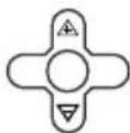
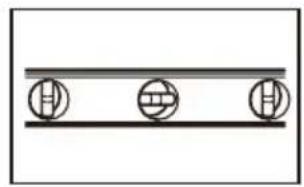
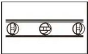
Simple diagram with three circular symbols on a horizontal line (no text or labels)Level
natural_image
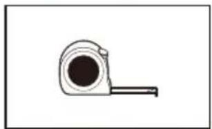
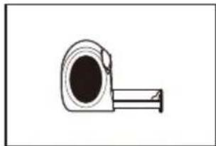
Simple line drawing of a tape measure (no text or symbols)Tape measure
natural_image
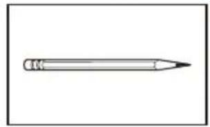
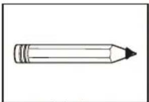
Simple line drawing of a pencil (no text or symbols)Pencil
natural_image
Line drawing of an adjustable wrench with a handle and screw (no text or symbols)Adjustable wrench or pliers
Packing List
| APPEARANCE | PART NAME | QUANTITY |
 | Window Air Conditioner | 1 |
 | Remote Control | 1 |
 | Long Foam Seal(Non-Adhesive) | 1 |
 | Long Foam Seal(Adhesive) | 1 |
| (WHD) (WHD) (WHD) (WHD) | 3/4" Screw | 4 |
 | Remote Control Battery | 2 |
 | Security Bracket | 1 |
 | 1/2" Screw | 3 |
 | Plasticine | 1 |
 | Panel Seal(Adhesive) | 2 |
 | 5/16" Long Hex-head Screw | 7 |
 | 1/2" Long Hex-head Screw | 2 |
 | 1/4" Long Hex-head Screw | 4 |
 | 5/8" Long Flat head Bolt and Locknut | 2 |
 | Sill Angel Bracket | 2 |
 | 1/2" Long Flat head Bolt and Locknut | 4 |
 | Gasket | 2 |
 | Mark "R" and "L" | 2 |
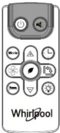
Operating Instructions
For remote control model
You can easily operate this air conditioner by press relevant button on the control panel as well as the remote controller.
| Clean the dust filter. | |
| Turn on/off the MONEY SAVER mode, under Cool/Dry mode | |
| Select to adjust the airflow direction by swinging the louver vertically. |
| Adjust fan speed (Auto,Low, Med, High)NOTE: Fan speed setting is available in Auto,Cool, and Fan modes only. | |
| Increase the air conditioning temperature. | |
| Decrease the air conditioning temperature. | |
| Mode | Switch between Cool/Dry/Fan/Auto mode. |
| Timer on or Timer off the unit. | |
| Turn on/off the MUTE mode. | |
| Turn on the air conditioner or switch to standby. | |
| Indication symbols of LED on control panel | |
| AUTO LOW MED HIGH | Indicates Automatic,Low,Medium and High fan speeds, respectively. |
 | Indicates the unit is in MUTE mode. |
 | Indicates the unit is in Sleep mode. |
| COOL DRY FAN AUTO | Indicates Cool, Dry, Fan, and Auto mode, respectively. |
 | Adjust fan speed (Auto,Low, Med, High)NOTE: Fan speed setting is available in Auto,Cool, and Fan modes only. |
 | Increase the air conditioning temperature. |
 | Decrease the air conditioning temperature. |
 | Switch between Cool/Dry/Fan/Auto mode. |
 | Timer on or Timer off the unit. |
 | Turn on/off the MUTE mode. |
 | Turn on the air conditioner or switch to standby. |
ASSEMBLY & INSTALLATION WINDOW MOUNTING
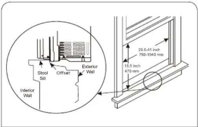
Step 1: Window Requirements
- This air conditioner is designed to be installed in a standard single-hung or double-hung window with a window width between 29.5" and 41" (750mm - 1040mm).
- The lower sash (the lower part of the window that moves up and down) must allow for 14.5" of vertical clearance when open.
- All supporting parts must be secured to firm wood, masonry, or metal.
- The electrical outlet must be within reach of the power cord. (Electrical outlets only, no power strips or other outlets allowed.) NOTE: Store the air conditioner in its product box while not in use.
WARNING
Excessive Weight Hazard
Use two or more people to move and install air conditioner. Failure to do so can result in back or other injury.
Step 2: Testing
Before installing your AC, test it to make sure it works properly, and your outlet has the proper power level.
First, place it on a flat surface, plug it directly into a wall outlet (never use a powerstrip or other device). and turn it on.
Next, use the Mode button on your control panel to change the AC to Cool Mode and press the down arrow to set the temperature to the lowest setting. After 3 minutes, the AC should be blowing cool air. If so, please continue to the next step. If not, see detailed troubleshooting tips at support.
Step 3: Prepare Air Conditioner for Installation
WARNING
Excessive Weight Hazard Use two or more people to move and install air conditioner.
Failure to do so can result in back or other injury.
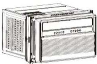
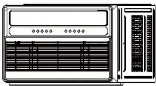
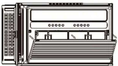
3A. Unpack the Air Conditioner
natural_image
Line drawing of a portable electronic device with ventilation grilles and control panel (no text or symbols)Remove Packaging Materials:
Gently handle the air conditioner while unpacking the unit.
Place the air conditioner on a hard, flat surface.
Remove tape and glue residue from surfaces before turning on the air conditioner. Rub a small amount of liquid dish soap over the adhesive with the fingers. Wipe with a damp cloth and dry.
Do not use sharp instruments, rubbing alcohol, flammable fluids, or abrasive cleaners to remove tape or glue. These products can damage the surface of the air conditioner.
Remove any packaging materials inserted into the side louvers. Dispose of/recycle packaging materials in an appropriate way.
3B. Remove filter and front panel
natural_image
Front view of a server rack unit with ventilation grilles and rack-mounted buttons (no text or labels visible)Pull down the front panel and remove the filter. Lift the front front panel upwards and remove from the air conditioner.
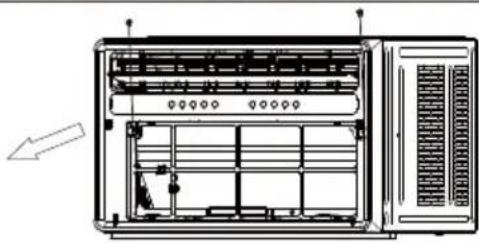
3C. Remove front panel and cabinet screws
natural_image
Technical line drawing of a server rack unit with ventilation grilles and internal components (no text or labels)Remove the four screws.
NOTE: The front panel screws must be reinstalled before mounting the air conditioner.
3D. Remove the connection
natural_image
Line drawing of a laptop computer monitor with scroll and keyboard (no text or symbols)Remove the cable connecting the display board.
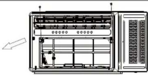
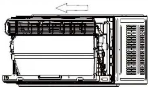
3E. Remove chassis
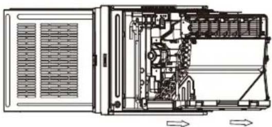
natural_image
Technical line drawing of an internal device with visible internal components and directional arrows (no text or symbols)Hold the cabinet while pulling on the base handle to install the unit.
IMPORTANT: To avoid damage, do not pull or lift near the top of the unit.
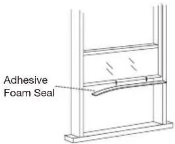
Step 4: Applying the Adhesive Foam Seal
Measure the length of the upper window frame, trim the adhesive foam seal to the appropriate length, and apply as shown below.
Step 5: Placing Inside an Open Window
Using team lift, gently lift the air conditioner and place in the windowsill. Next, close the window, making sure the air conditioner is centered and the bottom rail is flush against the windowsill.
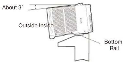
NOTE: The air conditioner should be tilted about 3^ to allow for better drainage of condensation and rainwater. Using a level, measure measure about 1/3 bubble for the correct slant.
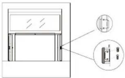
Step 6: Securing the Side Brackets
Extend the side brackets from both sides of the air conditioner onto the left and right window frames and secure by installing four 3/4" screws as shown.
NOTE: Fix the upper screws first, then the lower screws. When open the window, be sure that all the screws are fastened tightly.
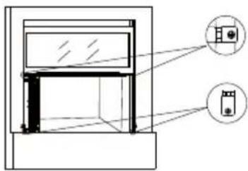
Step 7: Securing the Side Panels
Pull the side panels inwards to align with the brackets, then secure onto the sides by snapping the jutting points onto the locking pins. The side panels should be locked by 1/4" Long Hex-head Screw.
natural_image
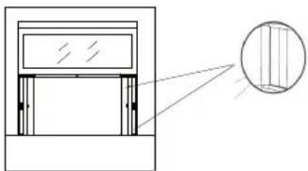
Technical line drawing of a door frame with an inset close-up showing internal components (no text or symbols)Step 8: Sealing Any Gaps with Modeling Clay (Plasticene)
Fill the crevices between the side brackets and panels with the included plasticene.
natural_image
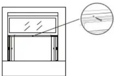
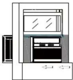
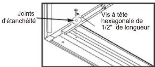
Architectural diagram showing a window frame with an inset close-up of vertical slats (no text or symbols)Step 9: Securing the Screw into the Top Rail
Secure the 1/2" Screw into the top rail of the air conditioner to the window frame.
natural_image
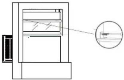
Simple line drawing of a window frame with an inset showing wood grain (no text or symbols)Step 10: Installing the Security Bracket (Recommended)
For security purposes, it is recommended to attach the security bracket to the top of the window using two 1/2" screws to prevent opening the window from outside. However, the security bracket can be removed to allow you to open the window when desired.
natural_image
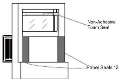
Technical line drawing of a mechanical assembly with an inset close-up showing internal components (no text or symbols)Step 11: Filling the Gap Between Sashes Applying the Panel Seals
Trim the non-adhesive foam seal to the appropriate length and insert between the window sashes.
When open the window, be sure that all the screws are fastened tightly from the AC unit curtain to the window frame. Measure the length extended by the side panels, trim the panel seals to the appropriate length, peel off the backings and apply on the panels on both sides.
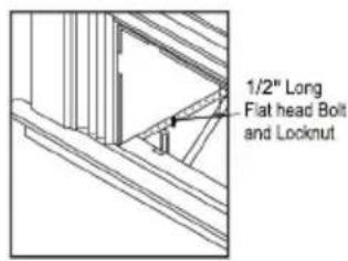
Step 12: Install Support Brackets
- Hold each support bracket flush against the outside of the window sill. Tighten each bracket to the bottom of the cabinet as shown below. Mark the brackets at top level of the window sill and then remove.
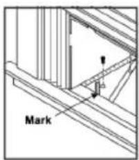
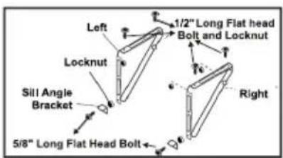
- Assemble the sill angle brackets to the support brackets at the marked position as shown above. Hand tighten, but not all the way for any changes that may need to be made later during installation.
- Install the support brackets (with sill angle brackets attached) to the bottom of the cabinet as shown below.
- Tighten all 6 bolts securely.
Step 13: Installing the Chassis into the Cabinet
- Using two or more people, lift the air conditioner and gently side it into the cabinet.
IMPORTANT: Do not push on the controls or finned coils. - Be sure the chassis is firmly seated in the back of the cabinet.
- Insert all screws removed during window installation (Step 3, 3C) and reattach the front panel, air filter and grille.
natural_image
Diagram of a refrigerator with front panel and side door, no text or symbols presentIf AC is Blocked by Storm Window Frame
Add wood as shown. Remove the storm window frame/obstruction before installing the window air conditioner. if the Storm Window Frame must remain, be sure the drain holes or slots are not caulked or painted shut. Accumulated rainwater or condensation must be allowed to drain out.
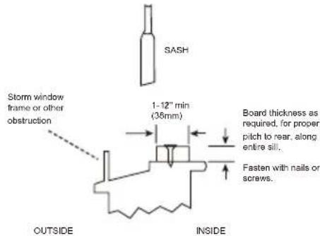
IMPORTANT: When opening the window, be sure that the fixed screws are secured properly in place without any objects affecting their attachment to the side brackets and associated window frame to prevent the unit from becoming unstable and falling.
ASSEMBLY & INSTALLATION-THRU-THE-WALL (CONT.)
Follow the widow installation step
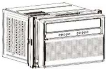
- Unpack the Air Conditioner
natural_image
Illustration of a multi-chamber electronic device with ventilation grilles and control panel (no text or symbols visible)- Remove faceplate screws
natural_image
Technical line drawing of a server rack unit with ventilation grilles and indicator lights (no text or labels)Remove the two faceplate screws.
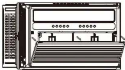
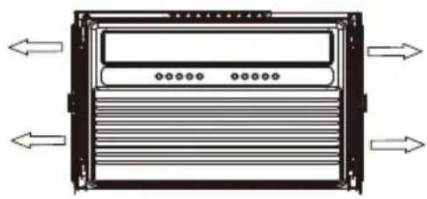
- Remove parts
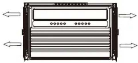
natural_image
Diagram of a server rack with ventilation ducts and directional arrows indicating flow (no text or labels)Remove Left Telescopic Curtain Support Assy. Remove Right Telescopic Curtain Support Assy.
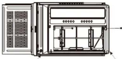
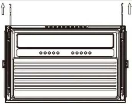
- Remove case screws
natural_image
Technical line drawing of a front view of an electronic device with ventilation grilles and a control panel (no text or symbols)Remove 2 screws fixed on left and right sides of case and chassis.
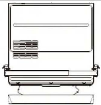
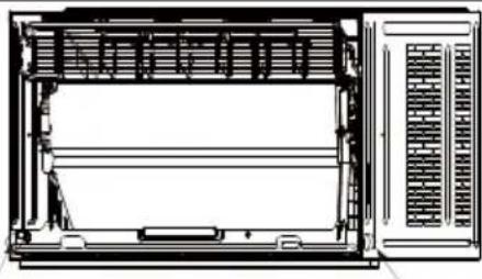
- Remove Hinge
natural_image
Technical line drawing of a rectangular electronic device with ventilation slots and mounting brackets (no text or symbols)- Remove chassis
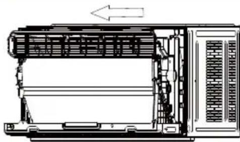
natural_image
Technical line drawing of a mechanical device with internal components and an arrow indicating direction (no text or symbols)- Remove filter and front panel
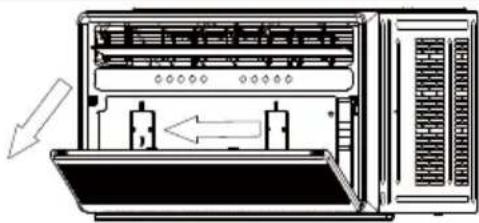
natural_image
Diagram of a server rack with two internal components and directional arrows indicating movement (no text or symbols)- Remove Upper guide rail
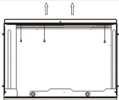
natural_image
Technical line drawing of a structural frame with supports and load arrows (no text or symbols)ASSEMBLY & INSTALLATION-THRU-THE-WALL (CONT.)
Prepare the Wall
- Prepare the wall in frame construction (including brick and stucco veneer).
the center of the installation area.
-
Cut a hole on each side of the center stud.
-
Measure between the inside edges of every other stud as shown below.
Measure and cut an opening with the following dimensions depending on your model.
WIDTH "X" = inside model plus twice the thickness of the framing material used.
HEIGHT "Y" = inside model eight plus twice the thickness of framing material used.
15K/18K/22K/24K
17.13 inch (435mm)
25.59 inch (650mm)
- Build a wooden frame with the inside dimensions of your model listed above (Measure twice).
The frame depth should be the same as the wall thickness. Fill in extra space from the opening to the studs with wood spacers as shown below.
the dry wall.
Y
NOTE
over the bottom of the frame opening to assure water is unable to enter the area between the inner and outer wall.
Prepare and Install the Cabinet
-
Slide the chassis from the cabinet. Refer back to the REMOVE CHASSIS instructions in the WINDOW MOUNTING section..
-
Place the cabinet into the opening with the bottom rail resting
-
Position the cabinet so it is tilted properly for water removal as seen below.
About 3°
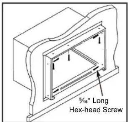
- Secure the bottom rail to the wood frame with two 1/2" Long Hex-head Screws and gaskets as shown below.
" Long
Hex-head Screw
ASSEMBLY & INSTALLATION-THRU-THE-WALL (CONT.)
Refer to the SUPPORT BRACKET ASSEMBLY in the WINDOW MOUNTING
Section to assemble the support brackets.
A wooden strip nailed to the outside wall should be used in conjunction with the angled sill support brackets.
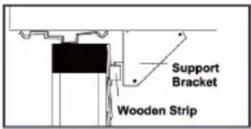
- Screw the cabinet to the wooden frame using shims as below with 7 long Hex-head screws, remember to maintain proper slope for water elimination.
- Install the chassis into the cabinet by following the steps described in the WINDOW MOUNTING section.
OPTIONAL: Caulking and installation of the trim on the interior wall may be done if desired.
Caulk the openings around the top and sides of the cabinet and all sides of the wood sleeve to the opening.
NOTE: See the WINDOW MOUNTING instructions for the bottom rail seal location.
Installing the Chassis into the Cabinet
natural_image
Line drawing of a server rack unit with ventilation grilles and indicator lights (no text or symbols)Push the chassis into the cabinet. Reinstall the screws of cabinet, and reattach the front facelate, front panel, and air filter.
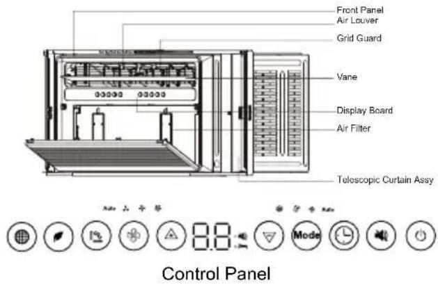
Other Features
Filter Reminder
When the running time reaches 500 hours, the filter reminder will light up to indicate the filter needs to be cleaned. Press and hold the Filter button for 5 seconds to reset the filter reminder.
Please see the maintenance section of this manual for filter cleaning instructions.
Display Auto Off
Display will dim after 30 seconds (or after 15 seconds in sleep mode) Wake up the display by pressing any button.
Memory
if the air conditioner is turned off but stays connected to the power, it will resume the previous settings (except the timer setting) when it is turned on again.
Drain Water
This unit was designed to collect moisture from condensation in a collection pan in the base of the unit. The collected water is distributed by the rear fan on to the condenser coil. This aids in the overall efficiency of the unit.
It is normal to hear the water sloshing around when the fan is spinning.
Operating the air conditioner properly helps you to obtain the best possible results.
( )
The fan motor will run for 1 minute, stop for 5 minutes, then run again.
( )Swing: Press SWING button to auto swing louvers, to control the air direction.
( ) MUTE : Press the MUTE button, the fan speed will change to mute speed.
Press POWER to turn ON the air conditioner.
Press POWER to turn OFF the air conditioner.
( ) The cooling function allows the air conditioner to cool the room and at the same time reduces air humidity. Press the MODE button to set the cooling function. Press the up or down arrow button to adjust the temperature.
( )
( )
, under fan mode.
Normal Operating Sounds
When the air conditioner is operating normally, you may hear sounds such as:
Droplets of water hitting the condenser, causing a pinging or clicking sound. The water droplets help cool the condenser.
Air movement from the fan.
Clicks from the thermostat cycle.
Vibrations or noise due to loose material in the wall or window construction.
A high-pitched hum or pulsating noise caused by the modern
Water will collect in the base pan during rain or days of high
part of the unit.
Clean Filter Reminder
conditioner features a Clear Filter reminder.
After 500 hours of operation, FILTER will
illuminate as a reminder that it is time to
See the "Air Conditioner Care" section for instructions on how
Using the Remote Control

POWER
- Press POWER to turn ON the air conditioner.
- Press POWER to turn OFF the air conditioner.


FAN SPEED
- Press FAN SPEED until the bar LED on the air conditioner control panel display for the desired setting.
- Choose Low, Medium, or High.
NOTES:
■ Auto fan speed and Temperature cannot be selected in Fan mode.


)Eco
Conserves energy by turning off compressor when the room reaches the desired temperature. The fan motor will run for 1 minute, stop for 5 minutes, then run again.
The compressor will turn back on when the room temperature rises above the set temperature. Press ECO to turn Eco feature on and off. When the unit is in Eco mode, the light will turn on.

Adjusting Temperature
Press the up arrow button to increase the set temperature. Press the down button to decrease the set temperature.

SLEEP
Automatically adjusts the temperature and fan speed to make the room more comfortable during the night. Press and hold the ≡(SLEEP) button until the sleep light turns on. All other lights will turn off. The set temperature will automatically increase by 1 degree every 30-60 minutes. At the end of the sleep cycle, the temperature will switch back to the originally set temperature.


(TIMER)

Delayed Shutoff:
Use the timer to set the air conditioner to turn off automatically after a 0.5- to 24-hour delay. The air conditioner must be ON):
- Press (TIMER). The display will show remaining time before the air conditioner will turn OFF.
- Press the up or down arrow button to change the delayed shut-off time from 0.5 to 24 hours. The time can be set in 0.5-hour increments below 10 hours and 1-hour increments for 10 hours or above.
- Press ⏻(TIMER) again to confirm setting. NOTE: The Set light will turn on while setting.
Delayed Start:
You can also set the air conditioner to turn on automatically after a 0.5- to 24-hour delay.
NOTE: After the set delay, the air conditioner will turn on with the previous settings. Change the mode, fan speed, and/or temperature before setting the timer, if desired.
- Turn OFF the air conditioner.
- Press ⏻(TIMER). Set the temperature by pressing the up or down arrow button.
- Press ⏻ (TIMER) a second time to set the rest time. Press the up or down arrow button to change the delay time from 0.5 to 24 hours.
- Press ⏻ (TIMER) again while the time remaining is shown on the display.
To Cancel Timer:
After the timer has been set, press ⏻ (TIMER).

)DISPLAY:

Press DISPLAY to switch on/off all lights or the LED display.

Swing: Press SWING button to auto swing air vane, to control the air direction.
( )MUTE : Press the QUIET button, the fan speed will change to mute speed.
Replacing the battery
Remove and replace batteries
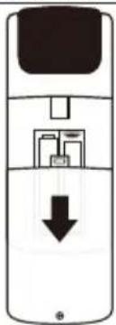
natural_image
Diagram of a mobile phone with a black downward arrow indicating a download or download process (no text or symbols present)Use a small Phillips screwdriver to loosen the battery cover screw. Slide the battery cover down with two thumbs to remove. Remove and properly dispose of old batteries, then replace with two new AAA batteries. Replace the battery cover and tighten the screw.
AIR CONDITIONER CARE
The air conditioner is designed to give you many years of dependable service. This section tells you how to clean and care for your air conditioner properly.
Air Filter Removal
The air filter is located behind the intake grille of air conditioner. Remove the air filter as follows:
■ Remove the filter by pulling down the indents of the filter door on the front of the unit as shown in below figure.
natural_image
Front view diagram of a rack-mounted server unit with ventilation slots and drive bays (no text or labels)Cleaning the Air Filter
The air filter is removable for easy cleaning. A clean filter helps remove dust, lint, and other particles from the air and is important for the best cooling and operating efficiency. Check the filter at least once per month to see whether it needs cleaning.
NOTE: Do not operate the air conditioner without the filter in place. Doing so will degrade the unit performance over time.
- Use a vacuum cleaner to clean the air filter.
- If the air filter is very dirty, use the liquid dish soap and warm water to wash the filter.
- Rinse the filter properly and shake the filter gently to remove the excess water.
- Let the filter dry completely before placing it into the air conditioner to ensure maximum efficiency
NOTE: Do not wash the air filter in the dishwasher or use any chemical cleaners; it may damage the filter.
Cleaning the Front Panel
- Turn off the air conditioner.r.
- Wipe the front panel with a soft, damp cloth.
- Air dry the front panel completely.
Repairing Paint Damage
Check once or twice a year for paint damage. This is very important, especially in areas near salt water or where rust is a problem. If needed, touch up with a good grade enamel paint.
Winter Storage
Unplug the unit prior to storing Cover the air conditioner with an appropriate cover to block outside air flow and to provide insulation
| Operation temp | indoor(cooling/heating) | 61°F-88°F |
| 64°F-09outdoor(cooling/l |
TROUBLESHOOTING
Before calling for service, try the suggestions below to see whether you can solve problem without outside help.
WARNING

Electrical Shock Hazard
Plug into a grounded 3 prong outlet.
Do not remove ground prong.
Do not use an adapter.
Do not use an extension cord.
Failure to follow these instructions can result in death, fire, or electrical shock.
| PROBLEM POSSIBLE CAUSES SOLUTIONS | ||
| The Air Conditioner Will Not Start | The air conditioner is unplugged. | Make sure the air conditioner plug is pushed completely into the outlet. |
| The fuse is blown/circuit breaker is tripped. | Check the house fuse/circuit breaker box and replace the fuse or reset the breaker. | |
| Power failure. | The unit will automatically restart when power is restored. There is a protective time delay(approx. 3 minutes) to prevent tripping and overloading the compressor.For this reason, the inthe first 3 mins, the unit may not cool as normal. | |
| The current interrupter device is tripped. | Press the RESET button located on the power cord plug. If the RESET button will not stay engaged, discontinue use of the air conditioner and contact a qualified service technician. | |
| The air conditioner does not cool as it should | Air flow is restricted. | Make sure there are no curtains, blinds or furniture blocking the front of the air conditioner. |
| The temperature control may not be set correctly. | Lower the set thermostat temperature. | |
| The air filter is dirty. | Clean the filer. Refer to Air Conditioner Care. | |
| The room may be too warm. | Please allow time for the room to cool down after turning on the air conditioner. | |
| Cold air is escaping. | Check for open furnace registers and cold air returns. | |
| The temperature sensor is not well situated. | Ensure the temperature sensor behind the air filter is not in contact with the cold coil. | |
| The air conditioner is freezing up. | Ice blocks the air flow and stops the air conditioner from cooling the room. | Switch to high fan speed and set the thermostat to a higher temperature. |
| The remote control is not working. | The batteries are inserted incorrectly. | Check the position of the batteries. |
| The batteries may be dead. Replace the batteries. | ||
| Water is dripping outside. | Hot and humid weather. This is normal. | |
| Water is dripping INSIDE when the unit is cooling. | The air conditioner is not correctly tilted outside. | Improper installation.Tilt air conditioner slightly to the outside to allow water drainage. Refer to installation in structions. |
| Water is dripping INSIDE when the unit is cooling. | Moisture removed from the air is draining into the base pan. | This is normal for a short period in areas with low humidity and normal for a longer period in areas with high humidity |
| Noise when the unit starts. | A"da-da"sound may occur for 30 seconds when the unit is turned on due to the compressor starting. | This is normal. |
ASSISTANCE OR SERVICE
Before calling for assistance or service, please check the "Troubleshooting" section. It may save you the cost of a service call. If you still need help, follow the instructions below.
When calling, please have the delivery date and the complete model and serial numbers of the appliance. This information will help us to better respond to the request.
In the USA
Call XLS Products Customer Service toll free: 1-800-207-1156.
Our consultants provide assistance with:
■ Features and specifications on our full line of appliances.
■ Installation information.
■ Use and maintenance procedures.
■ Accessory and repair parts.
■ Specialized customer assistance.
■ Referrals to local dealers, repair parts distributors, and service companies. XLS Products-designated service technicians are trained to fulfill the product warranty and provide after-warranty service, anywhere in the United States.
For further assistance:
If you need further assistance, you can write to XLS Products with any questions or concerns at:
XLS Products, Inc.
Customer Service
P.O. Box 16262
Philadelphia, PA 19114-0262
Please include a daytime phone number in your correspondence.
In Canada
Call XLS Products Customer Service toll free: 1-800-207-1156.
Our consultants provide assistance with:
■ Features and specifications on our full line of appliances.
■ Use and maintenance procedures.
■ Accessory and repair parts.
■ Referrals to local dealers, repair parts distributors, and service companies. XLS Products-designated service technicians are trained to fulfill the product warranty and provide after-warranty service, anywhere in Canada.
For further assistance:
If you need further assistance, you can write to XLS Products with any questions or concerns at:
XLS Products, Inc.
Customer Service
P.O. Box 16262
Philadelphia, PA 19114-0262
Please include a daytime phone number in your correspondence.
XLS PRODUCTS WARRANTY FOR WHIRLPOOL® AIR CONDITIONERS
ONE YEAR LIMITED WARRANTY
For one year from no earlier than date of delivery, when this product is operated and maintained according to instructions attached to or furnished with the product, XLS Products will pay for product replacement (at our discretion) to correct defects in materials or workmanship.
ITEMS XLS PRODUCTS WILL NOT PAY FOR
- Service calls to correct the installation of your product, instruct you how to use your product, to replace house fuses or reset circuit breakers, replace or clean filters, or correct house wiring.
- Service calls to repair or replace air filters. Those consumable parts are excluded from warranty coverage.
- Repairs when your product is used for other than normal, single-family household use.
- Damage resulting from accident, alteration, misuse, abuse, fire, flood, acts of God, improper installation, installation not in accordance with electrical or plumbing codes, or use of products not approved by XLS Products.
- Replacement parts or repair labor costs for units operated outside the United States or Canada.
- Pickup and delivery. This product is designed to be repaired in the home.
- Repairs to parts or systems resulting from unauthorized modifications made to the appliance.
- Expenses for travel and transportation for product service in remote locations.
- The removal and reinstallation of your appliance if it is installed in an inaccessible location or is not installed in accordance with published installation instructions.
DISCLAIMER OF IMPLIED WARRANTIES; LIMITATION OF REMEDIES
CUSTOMER'S SOLE AND EXCLUSIVE REMEDY UNDER THIS LIMITED WARRANTY SHALL BE PRODUCT REPAIR AS PROVIDED HEREIN. IMPLIED WARRANTIES, INCLUDING WARRANTIES OF MERCHANTABILITY OR FITNESS FOR A PARTICULAR PURPOSE, ARE LIMITED TO ONE YEAR OR THE SHORTEST PERIOD ALLOWED BY LAW. XLS PRODUCTS SHALL NOT BE LIABLE FOR INCIDENTAL OR CONSEQUENTIAL DAMAGES. SOME STATES AND PROVINCES DO NOT ALLOW THE EXCLUSION OR LIMITATION OF INCIDENTAL OR CONSEQUENTIAL DAMAGES, OR LIMITATIONS ON THE DURATION OF IMPLIED WARRANTIES OF MERCHANTABILITY OR FITNESS, SO THESE EXCLUSIONS OR LIMITATIONS MAY NOT APPLY TO YOU. THIS WARRANTY GIVES YOU SPECIFIC LEGAL RIGHTS AND YOU MAY ALSO HAVE OTHER RIGHTS, WHICH VARY, FROM STATE TO STATE OR PROVINCE TO PROVINCE.
Outside the 50 United States and Canada, this warranty does not apply. Contact your authorized XLS Products dealer to determine if another warranty applies.
If you need service, first see the "Troubleshooting" section of the Use & Care Guide. After checking "Troubleshooting," additional help can be found by checking the "Assistance or Service" section or by calling XLS Products. In the U.S.A., call 1-800-207-1156. In Canada, call 1-800-207-1156.
Keep this book and your sales slip together for future reference. You must provide proof of purchase or installation date for in-warranty service.
Write down the following information about your air conditioner to better help you obtain assistance or service if you ever need it. You will need to know your complete model number and serial number. You can find this information on the model and serial number label located on the product.
Dealer name ____
Address
Phone number
Model number ____
Serial number
Purchase date ____
ASSISTANCE OU SERVICE 19
GARANTIE DES PRODUITS XLS POUR LES CLIMATISEURS WHIRLPOOL® 20
Modèles:
WHAW-151IN
WHAW-181IN
WHAW-241IN
SÉCURITÉ DU CLIMATISEUR
1 Battery march Park
Quincy, MA 02269
natural_image
Line drawing of a screwdriver with a flat head and threaded shaft (no text or symbols)Tournevis cruciforme
natural_image
Simple diagram with three circular symbols on a horizontal line, no text or labels presentNiveau
natural_image
Simple line drawing of a tape measure (no text or symbols)Mètre ruban
natural_image
Simple line drawing of a pencil with eraser (no text or symbols)Crayon
natural_image
Line drawing of an adjustable wrench with a handle and screw (no text or symbols)natural_image
Line drawing of a portable electronic device with ventilation grilles and control panel (no text or symbols)natural_image
Front view diagram of a server rack unit with ventilation grilles and drive bays (no text or labels)natural_image
Technical line drawing of a server rack unit with ventilation grilles and internal components (no text or labels)Retirez les quatre vis.
natural_image
Technical line drawing of a mechanical device with no visible text or symbolsnatural_image
Technical line drawing of an internal device with visible internal components and directional arrows (no text or symbols)natural_image
Technical line drawing of a door frame with an inset close-up showing internal components (no text or symbols)natural_image
Architectural cross-section diagram showing structural components and a magnified inset of vertical slats (no text or labels)natural_image
Simple line drawing of a window frame with an inset showing a wooden object (no text or symbols)natural_image
Technical line drawing of a mechanical assembly with an inset circular detail showing a component (no text or symbols)natural_image
Architectural line drawing of a window frame structure (no text or symbols)Étape 13: Installing the Chassis into the Cabinet
natural_image
Diagram of a refrigerator with front panel and side door, no text or symbols presentnatural_image
Line drawing of a portable electronic device with ventilation grilles and control panel (no text or symbols)5.Retirez les vis de la plaque frontale.
natural_image
Technical line drawing of a server rack unit with ventilation grilles and ventilation ducts (no text or labels)- Retirez les pièces.
natural_image
Diagram of a server rack with directional arrows indicating data flow or movement (no text or symbols)natural_image
Technical line drawing of a front view of an air conditioner unit (no text or symbols)natural_image
Technical line drawing of a rectangular electronic device with ventilation grilles and mounting brackets (no text or symbols)- Retirez la chaisse
natural_image
Technical line drawing of a mechanical device with internal components and an arrow indicating direction (no text or symbols)natural_image
Diagram of a server rack with two ports and directional arrows indicating movement (no text or symbols)natural_image
Technical line drawing of a structural frame with supports and load arrows (no text or symbols)ASSEMBLAGE & INSTALLATION À TRAVERS LE MUR (CONT.)
Préparez le mur
- Secure the bottom rail to the wood frame with two 1/2 Long Hex-head Screws and gaskets as shown below.
natural_image
Diagram of a mobile phone with a black download arrow indicating left-side control (no text or symbols)natural_image
Front view diagram of a server rack unit with ventilation grilles and rack-mounted ports (no text or labels)ASSISTANCE OU SERVICE
Philadelphia, PA 19114-0262
Philadelphia, PA 19114-0262
GARANTIE DES PRODUITS XLS POUR LES CLIMATISEURS WHIRLPOOL®
GARANTIE LIMITÉE D'UN AN
Recommended Grounding Method
natural_image
Line drawing of a screwdriver with a flat head and threaded shaft (no text or symbols)Destornillador Phillips
natural_image
Simple diagram with three circular symbols on a horizontal line, no text or labels presentNivel
natural_image
Simple line drawing of a measuring tool (no text or symbols)Cinta métrica
natural_image
Simple line drawing of a pencil (no text or symbols)Lápiz
natural_image
Line drawing of a adjustable wrench with a handle and spout (no text or symbols)Llave ajustable o pinzas
Lista de Embalaje
When open the window, be sure that all the screws are fastened tightly.
natural_image
Technical line drawing of a mechanical assembly with a magnified inset showing internal components (no text or symbols)natural_image
Architectural line drawing of a window frame structure (no text or symbols)natural_image
Diagram of a refrigerator with front panel and side door, no text or symbols presentnatural_image
Illustration of a rack-mounted server unit with ventilation grilles and ventilation grilles (no text or symbols visible)natural_image
Technical line drawing of a server rack unit with ventilation grilles and ventilation ducts (no text or labels)natural_image
Diagram of a server rack with heat exchangers and directional arrows indicating flow (no text or labels)natural_image
Technical line drawing of a front panel with internal components and ventilation grilles (no text or symbols)natural_image
Technical line drawing of a rectangular electronic device with ventilation grilles and mounting brackets (no text or symbols)- Quitar ell chasis

natural_image
Technical line drawing of a mechanical device with internal components and an arrow indicating direction (no text or symbols)natural_image
Diagram of a server rack with two internal components and directional arrows indicating movement (no text or symbols)natural_image
Technical line drawing of a structural frame with supports and load arrows (no text or symbols)natural_image
Diagram of a mobile phone with a black downward arrow indicating a download or download process (no text or symbols present)natural_image
Front view diagram of a rack-mounted server unit with ventilation grilles and drive bays (no text or labels)Philadelphia, PA19114-0262
Philadelphia, PA19114-0262