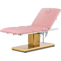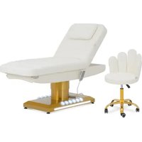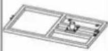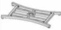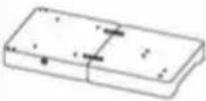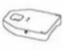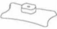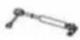
Ardea - Chair Physa - Free user manual and instructions
Find the device manual for free Ardea Physa in PDF.
| Product type | Aesthetic care chair (cosmetic bed) |
| Brand | Physa |
| Model | Ardea (PHYSA ARDEA BLANC) |
| Dimensions (L x W x H) | 790 x 1790 x 1170 mm |
| Weight | 40.1 kg |
| Maximum capacity | 200 kg |
| Main material | Steel with faux leather and foam upholstery |
| Intended use | Professional: beauty salons, spas, wellness centers, clinics |
| Operating environment | Indoor only, ambient temperature ≤ 45°C, humidity ≤ 85% |
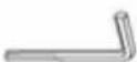
| Assembly required | Yes, with screws and Allen key provided |
| Cleaning | Soft slightly damp cloth, non-corrosive detergents |
| Maintenance | Check screws and stability regularly; do not immerse |
| Safety | Warning label on product; do not exceed maximum load |
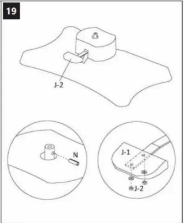
| Spare parts | Available through manufacturer or authorized dealer |
| Repairability | Repairs by the manufacturer's service center only |
| Warranty | Legal warranty; contact customer service for more information |
Frequently Asked Questions - Ardea Physa
User questions about Ardea Physa
0 question about this device. Answer the ones you know or ask your own.
Ask a new question about this device
Download the instructions for your Chair in PDF format for free! Find your manual Ardea - Physa and take your electronic device back in hand. On this page are published all the documents necessary for the use of your device. Ardea by Physa.
USER MANUAL Ardea Physa
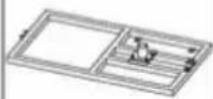
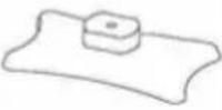
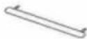
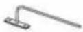
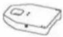
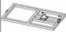
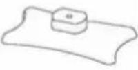
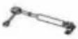
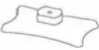
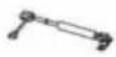
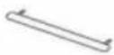
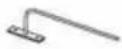
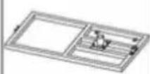
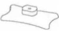
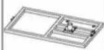
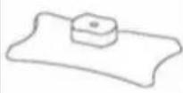
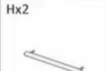
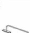
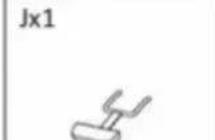
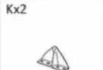
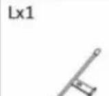
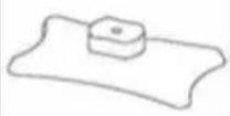
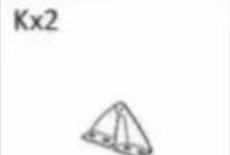
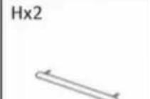
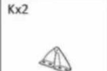
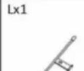
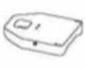
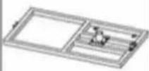
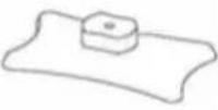
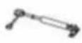
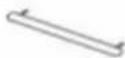
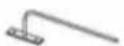
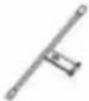
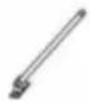
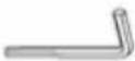
| Ax1 | Bx1 | Cx1 | Dx1 | Ex1 | Fx1 |
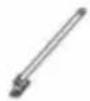
![]() | ![]() | ![]() | ![]() | ![]() | ![]() |
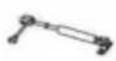
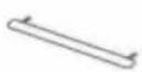
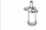
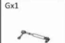
| Gx1 | Hx2 | Ix1 | Jx1 | Kx2 | Lx1 |
![]() | ![]() | ![]() | ![]() | ![]() | ![]() |
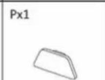
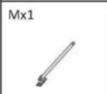
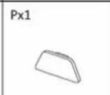
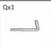
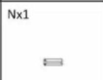
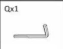
| Mx1 | Nx1 | Ox4 | Px1 | Qx1 | |
![]() | ![]() | ![]() | ![]() | ![]() |
text_image
3 D Sx4 Sx4
text_image
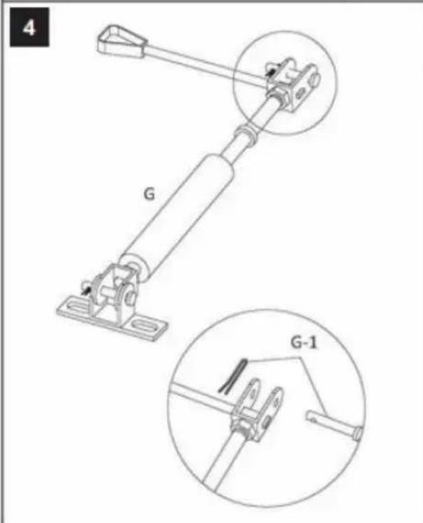
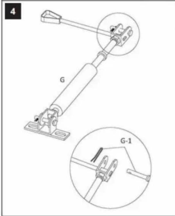
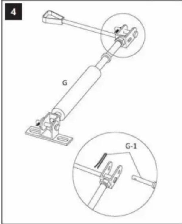
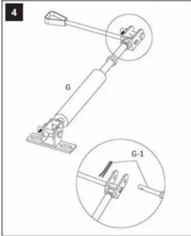
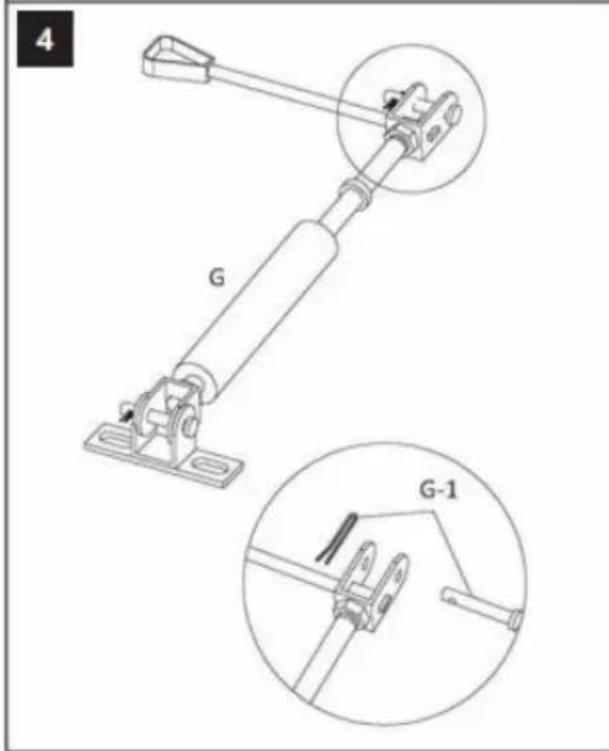
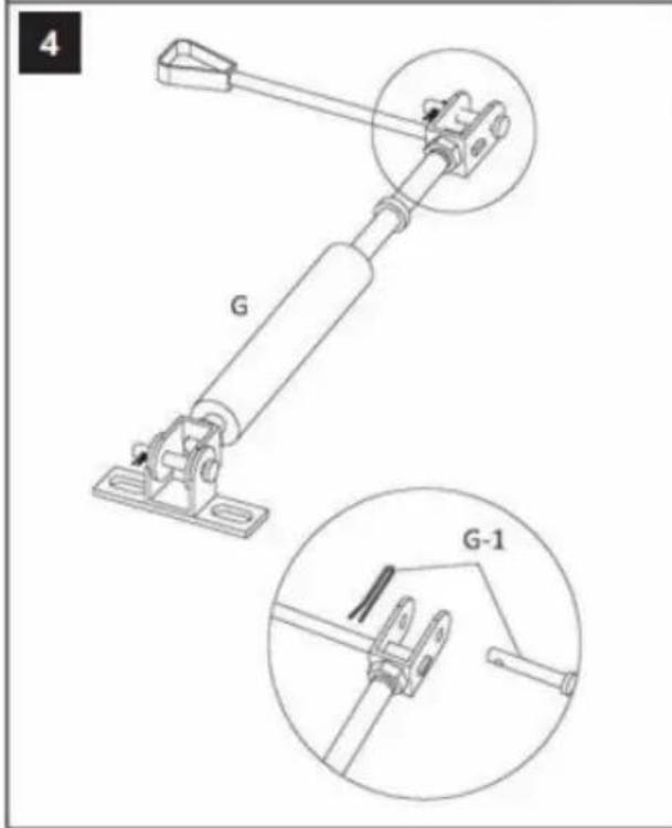
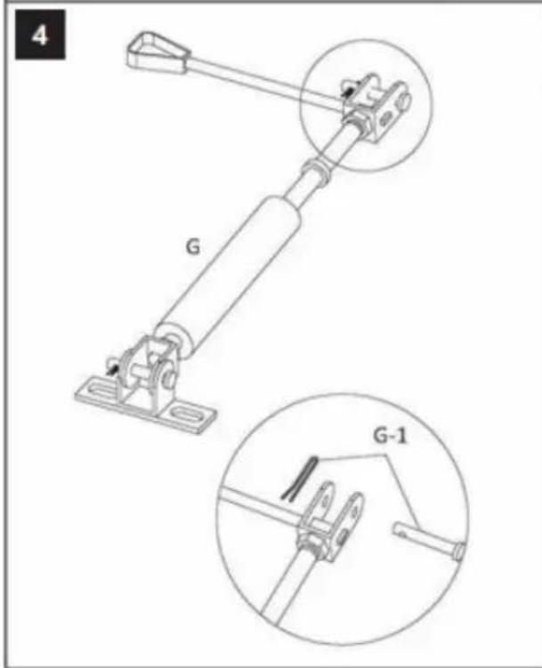
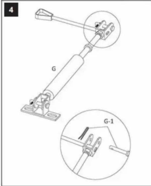
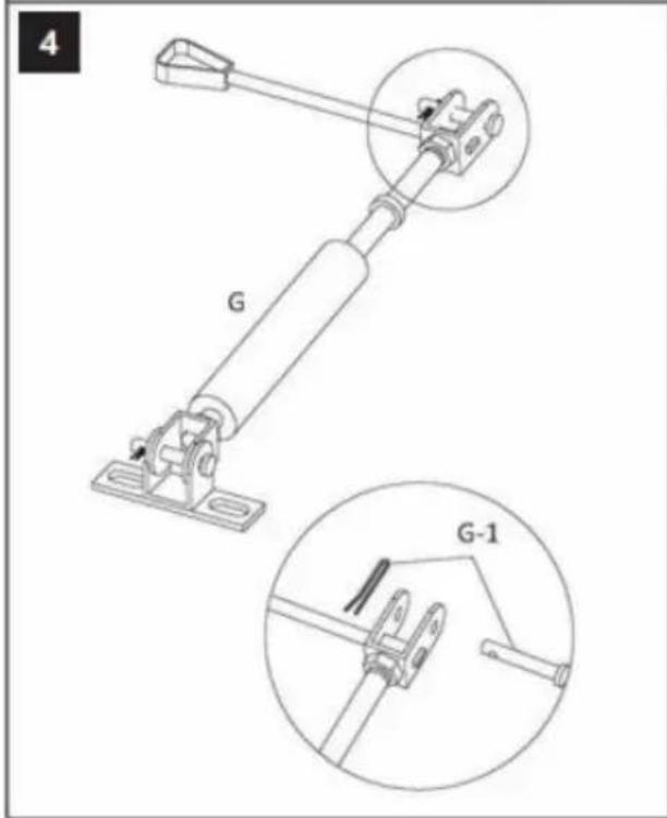
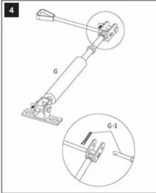
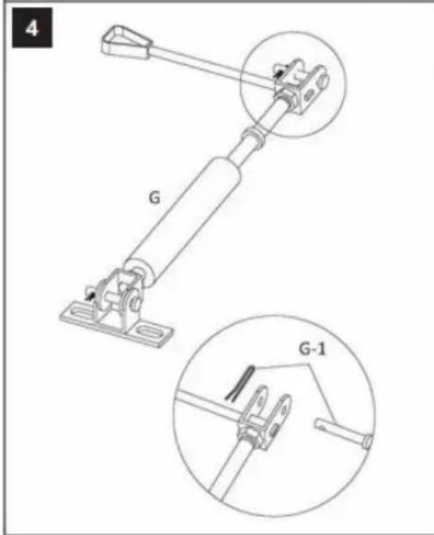
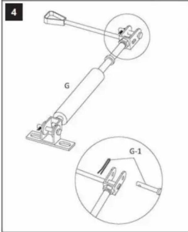
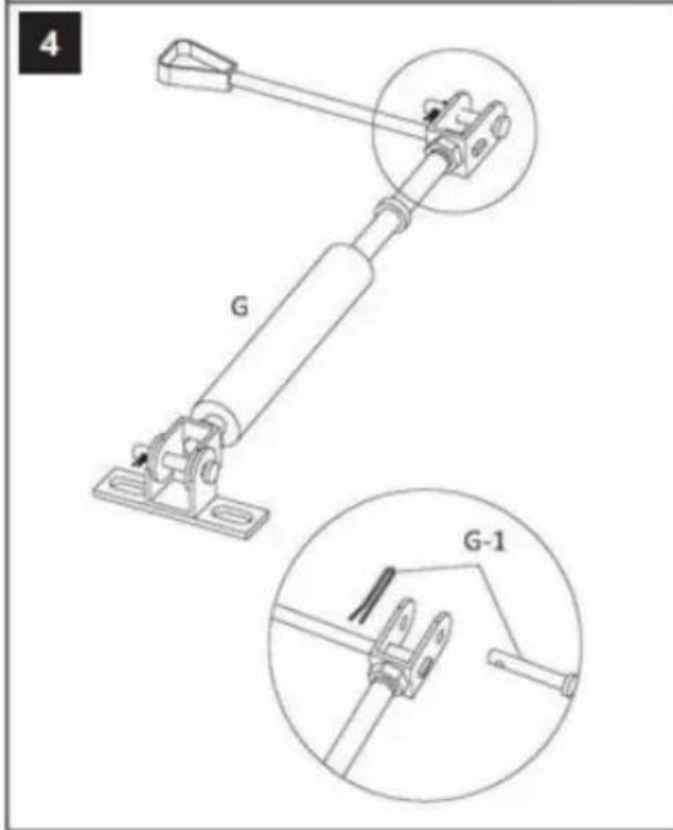
4 G G-1
text_image
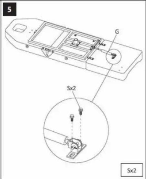
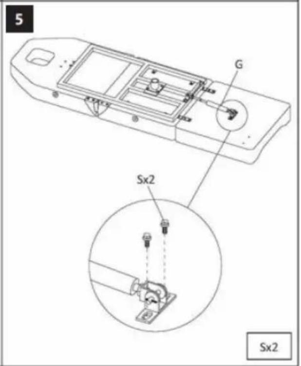
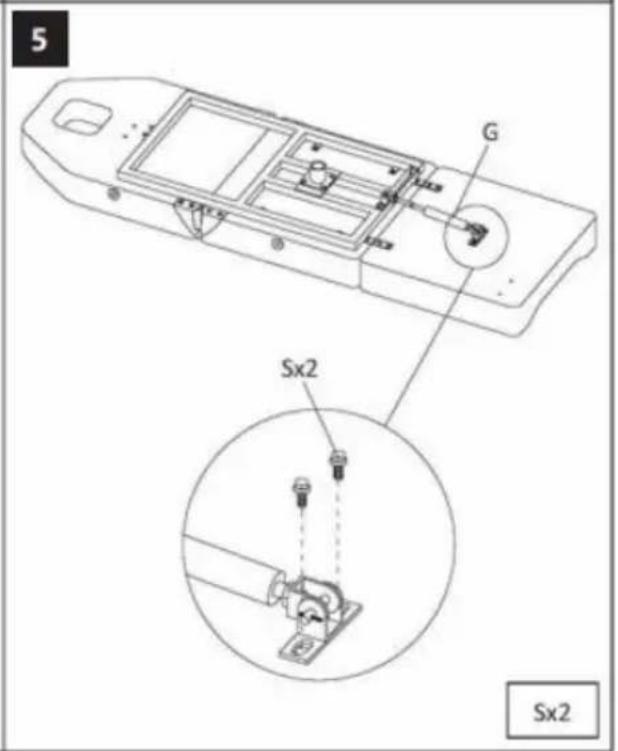
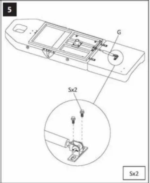
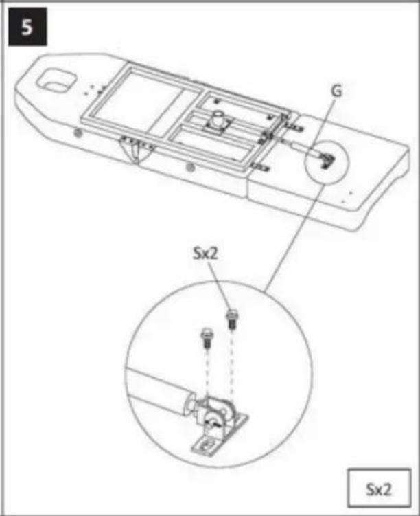
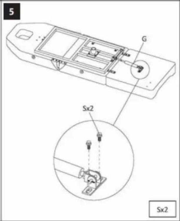
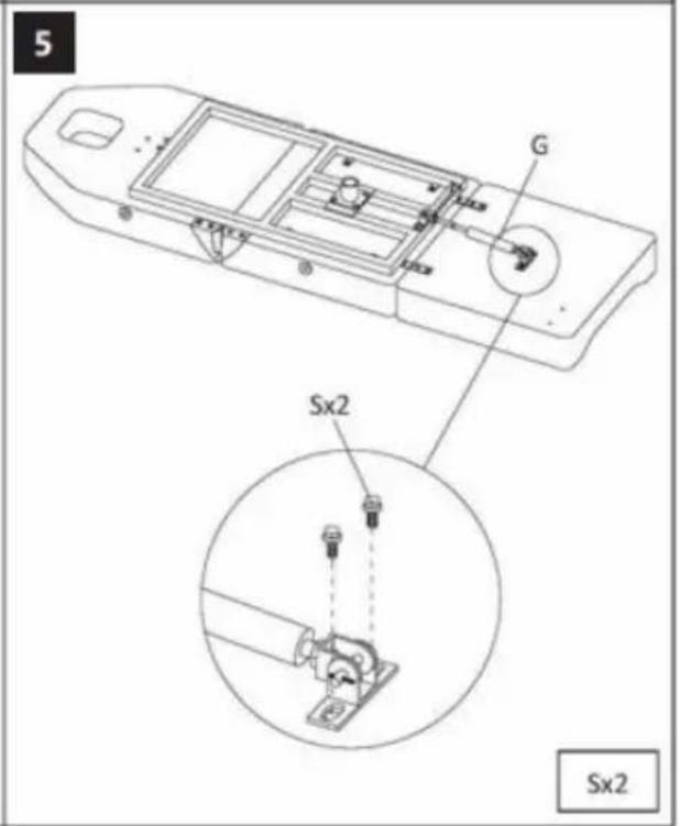
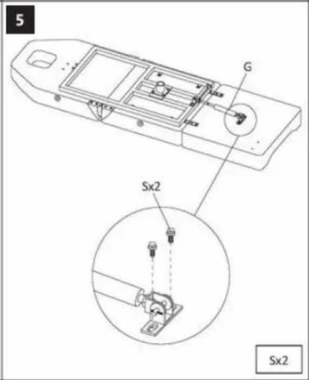
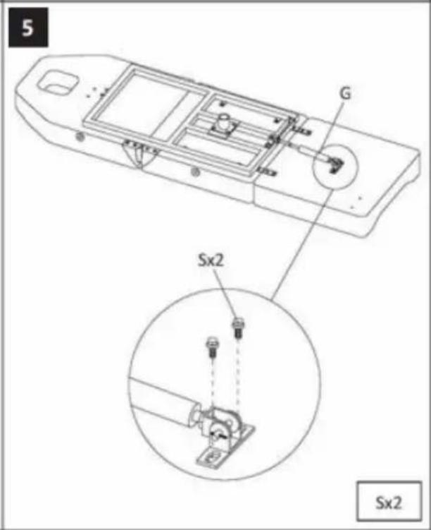
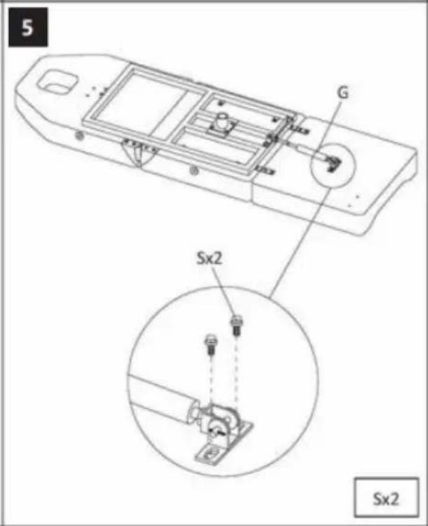
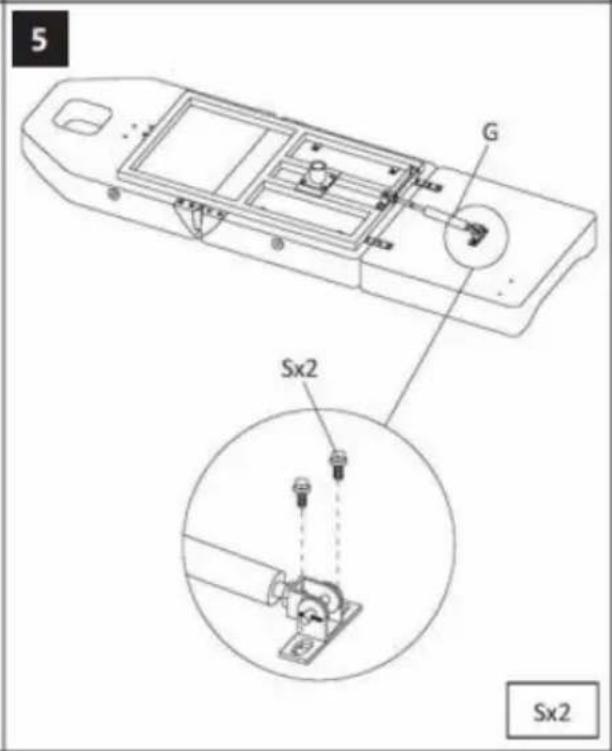
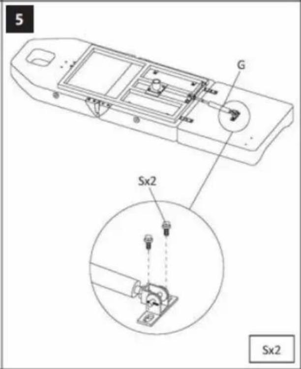
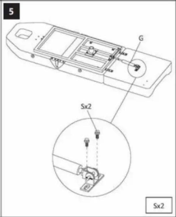
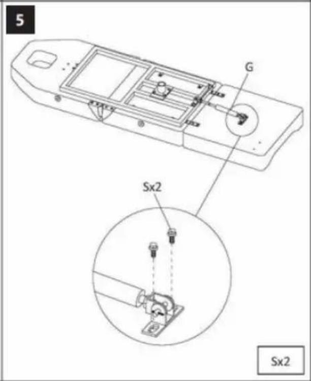
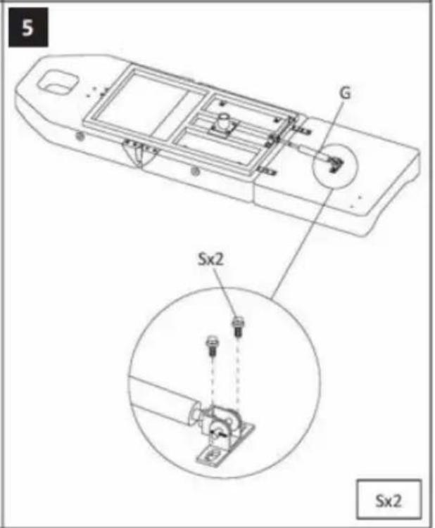
5 G Sx2 Sx2
text_image
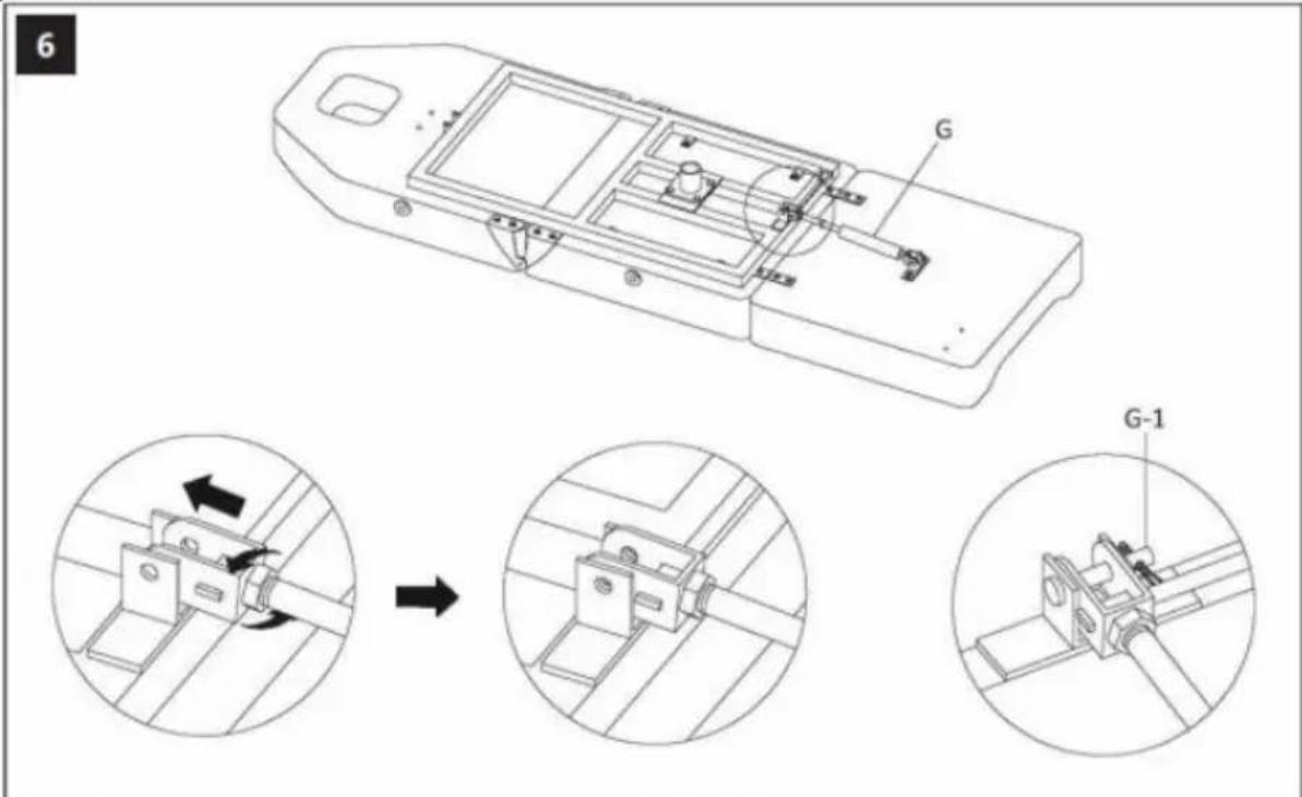
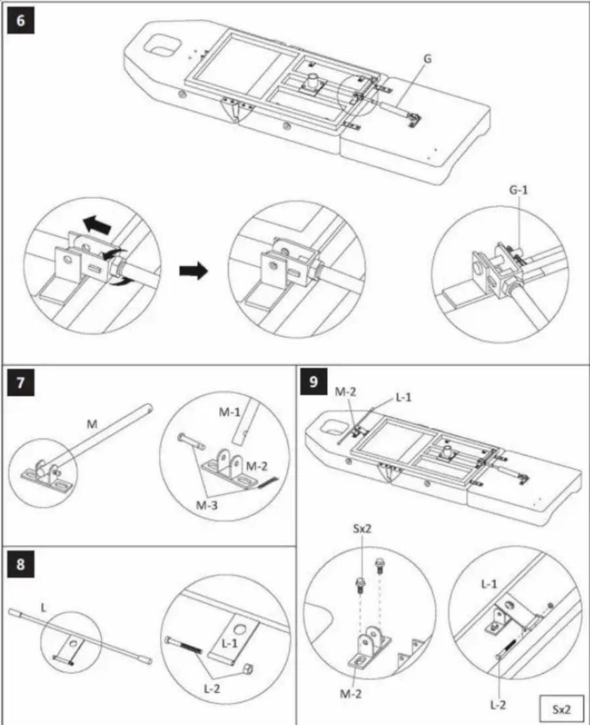
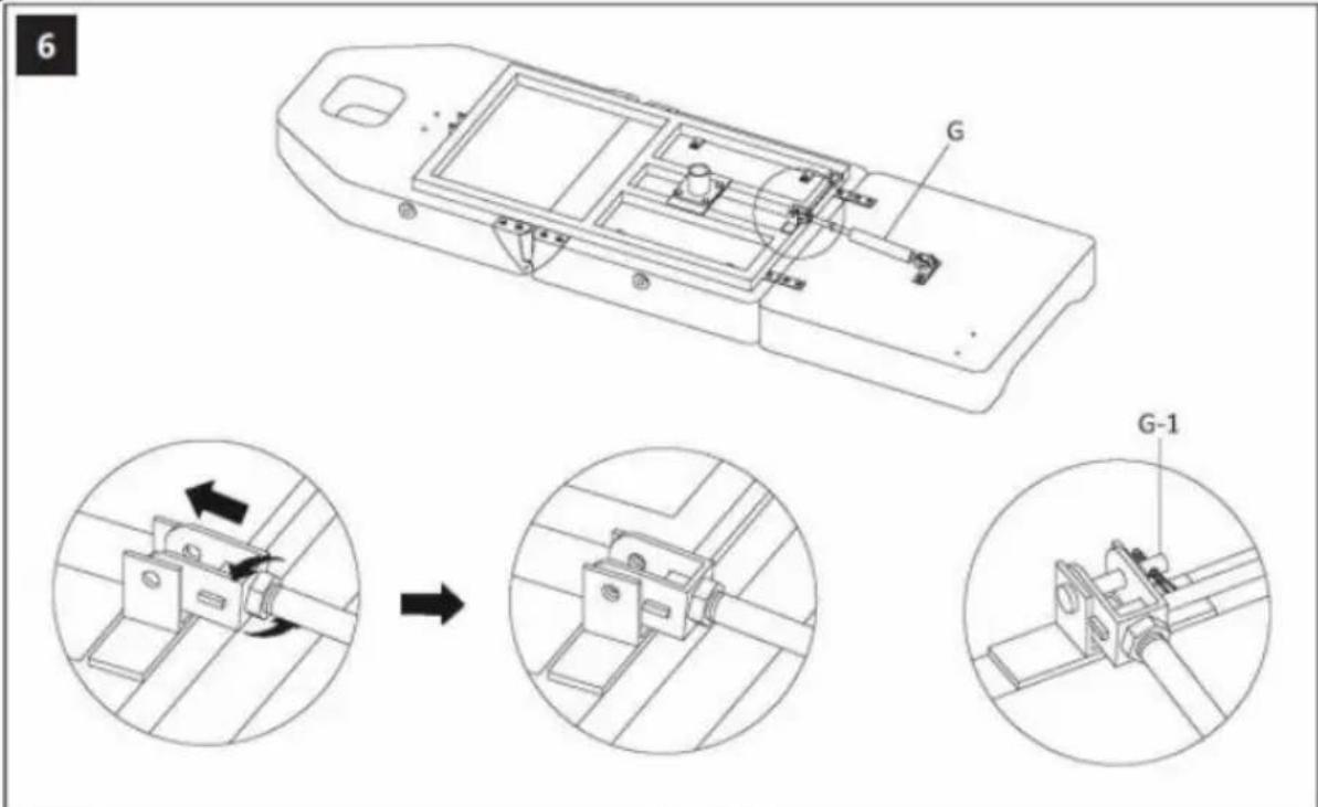
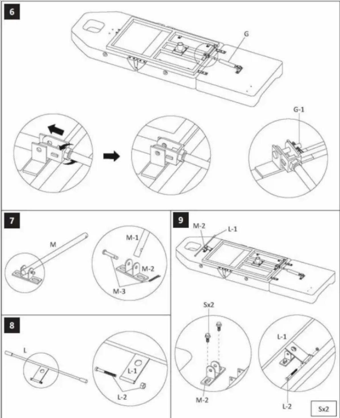
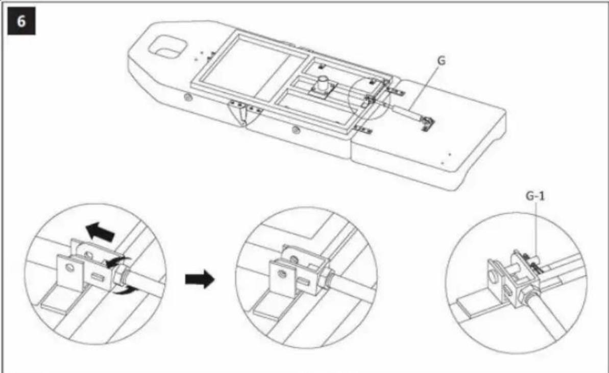
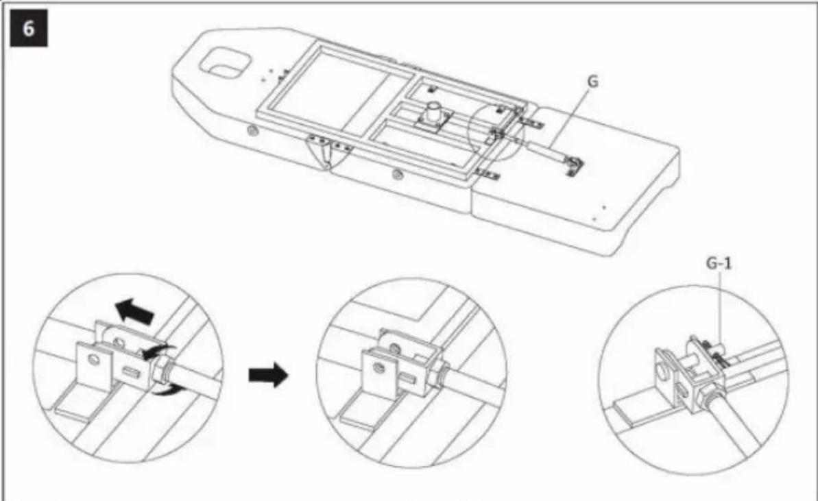
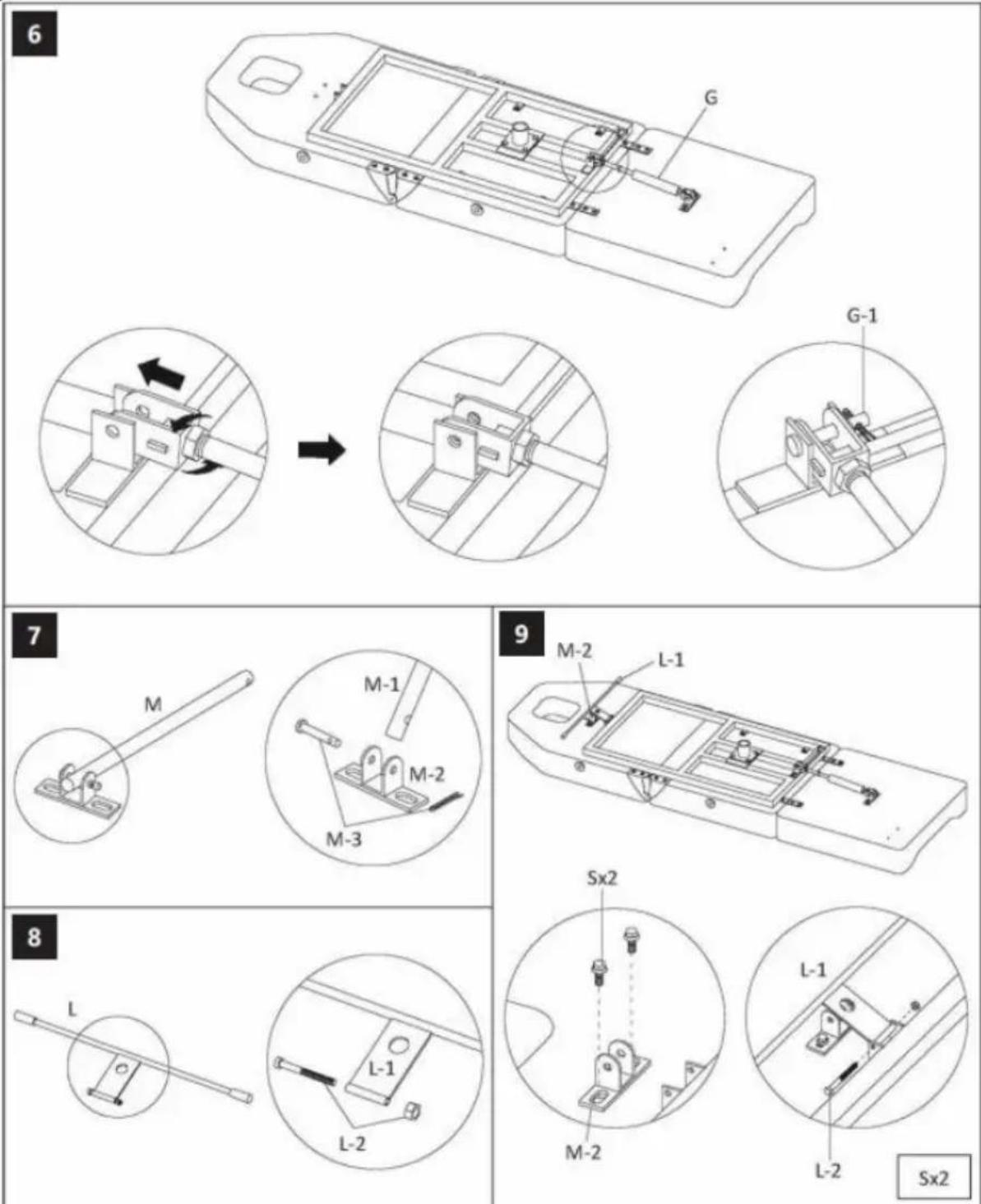
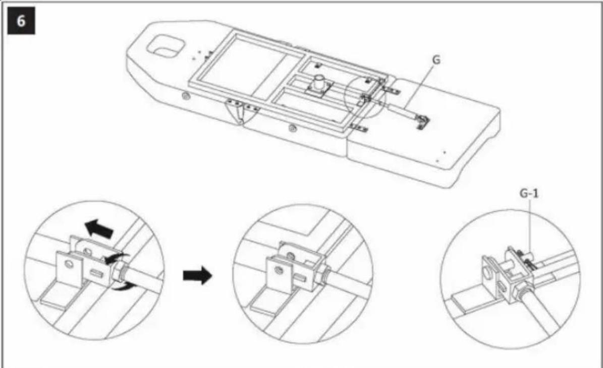
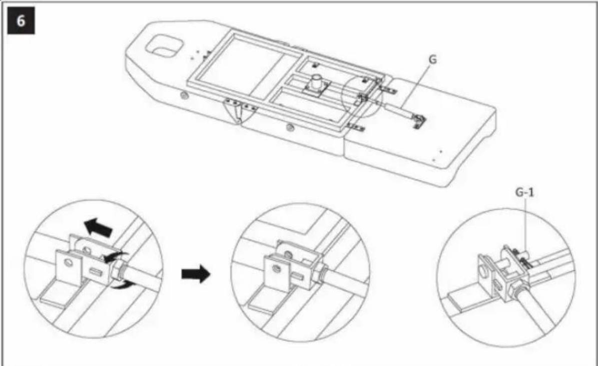
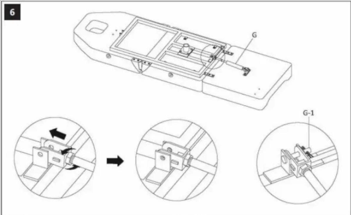
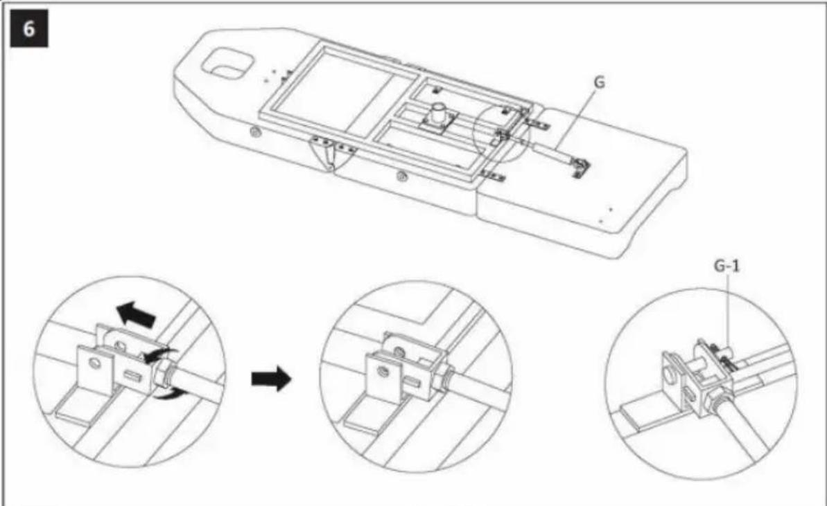
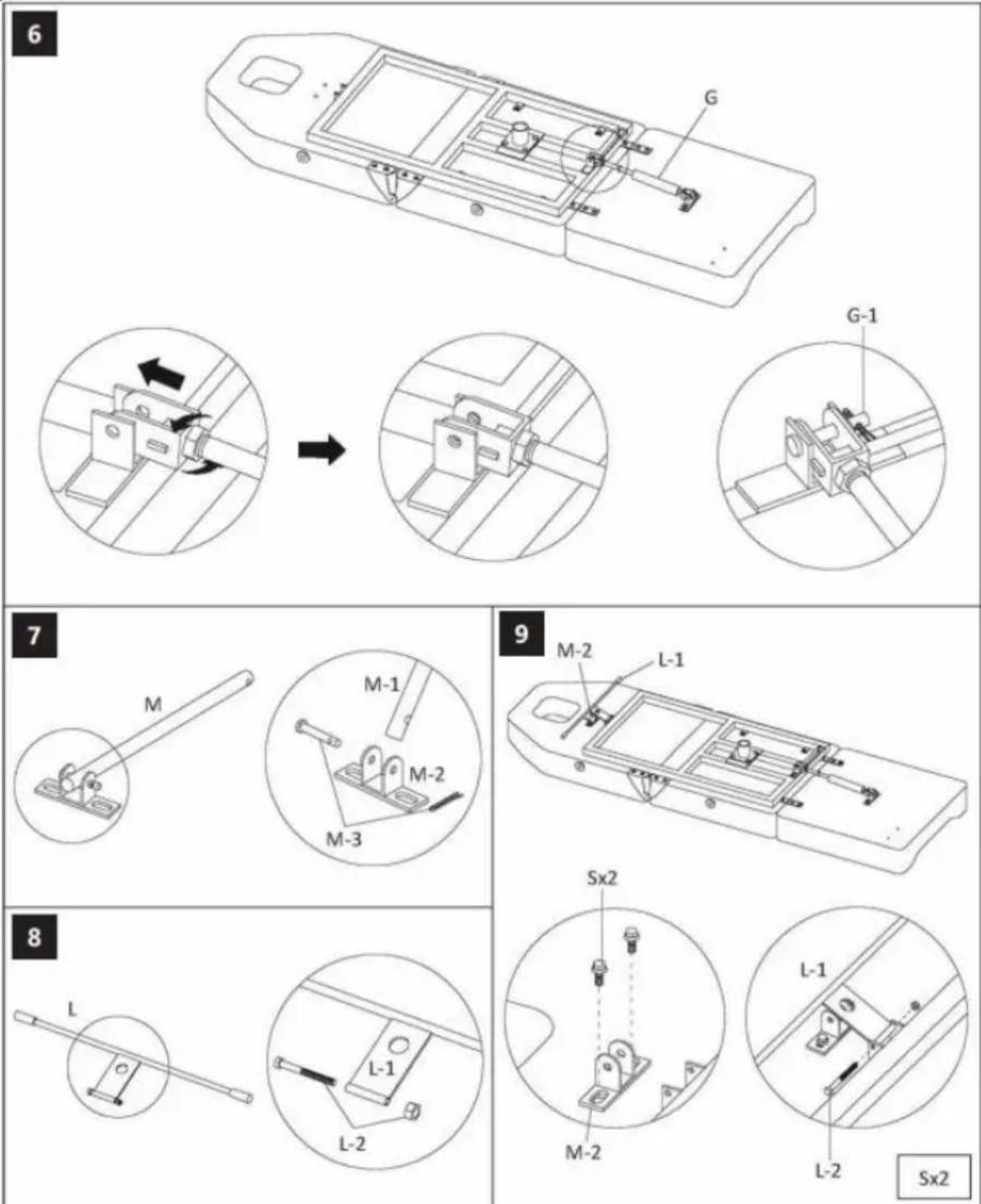
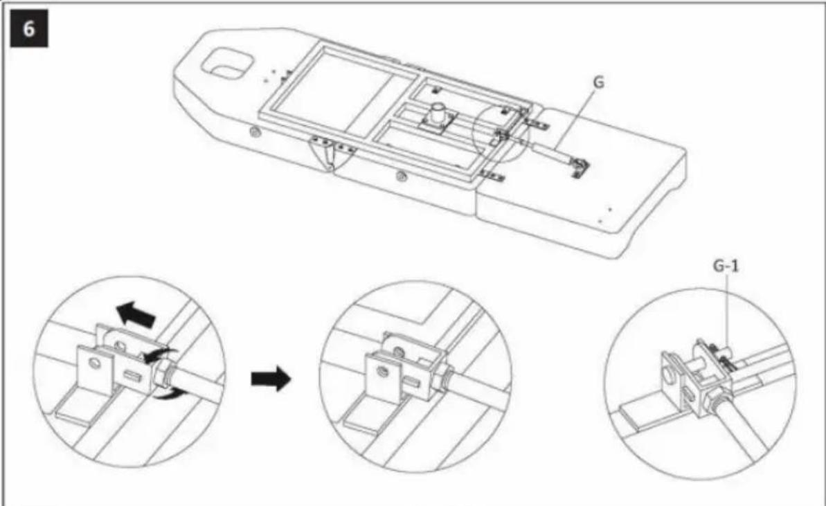
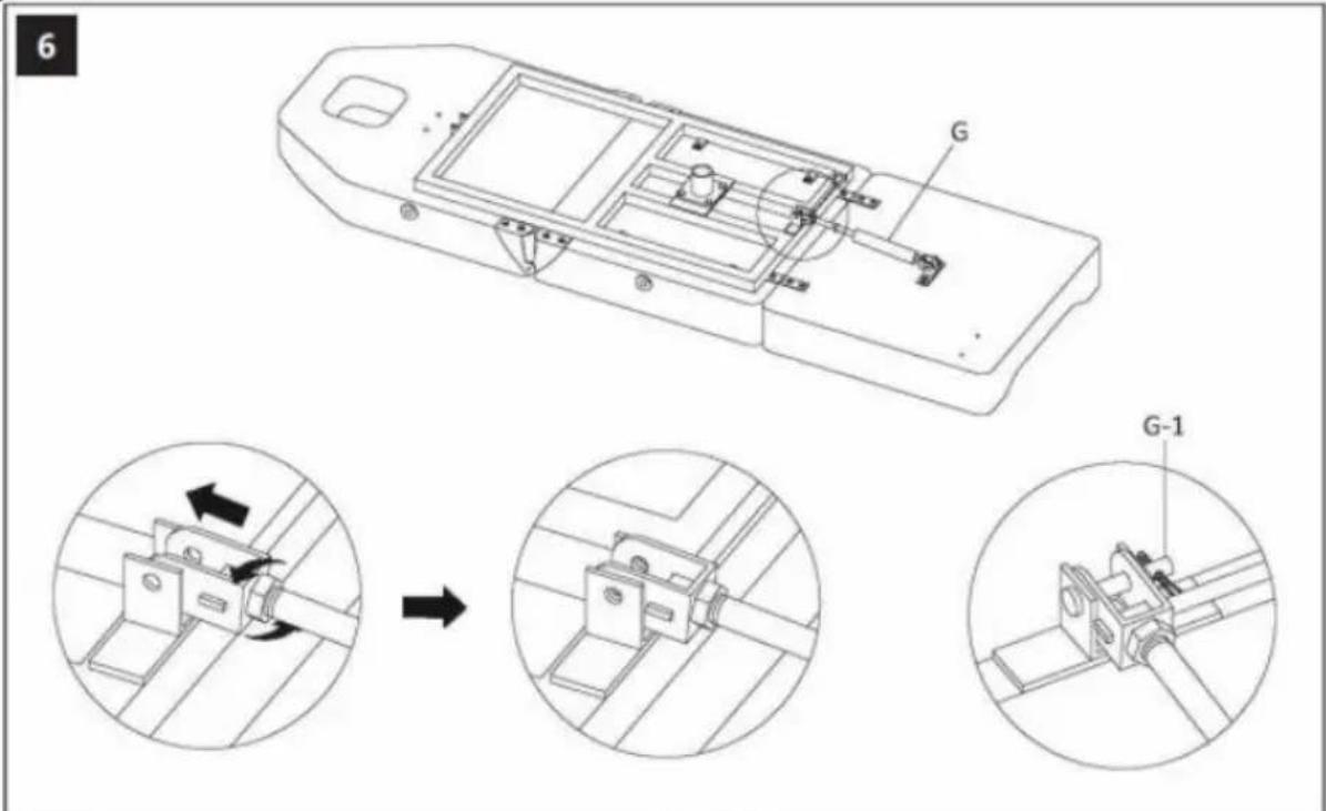
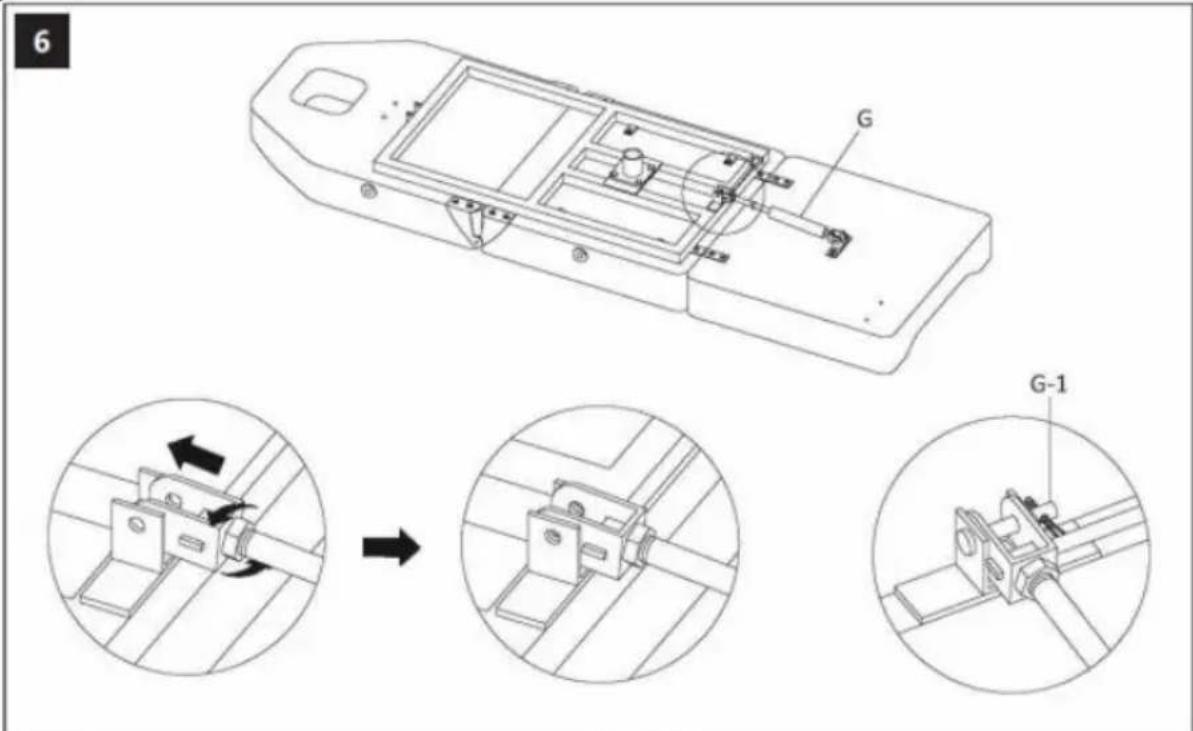
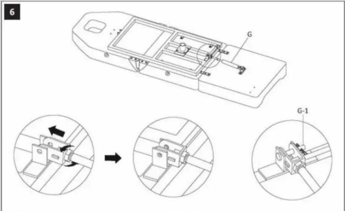
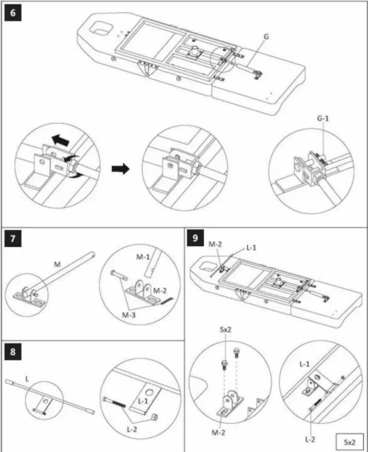
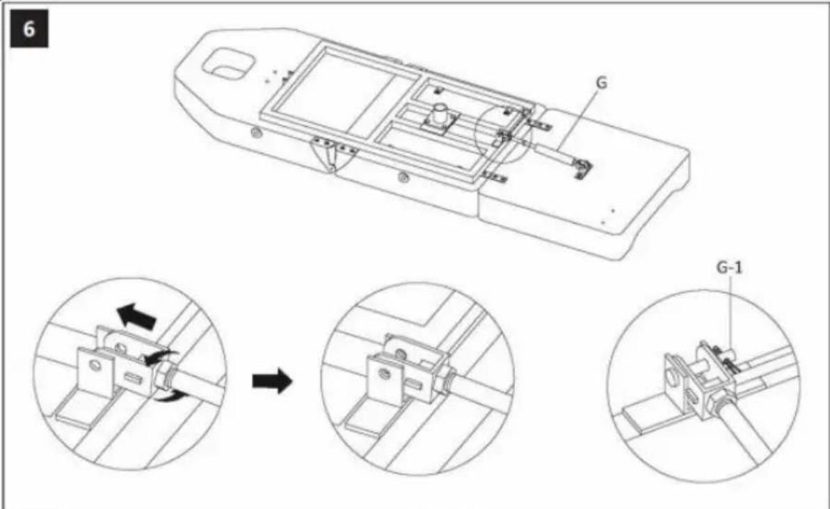
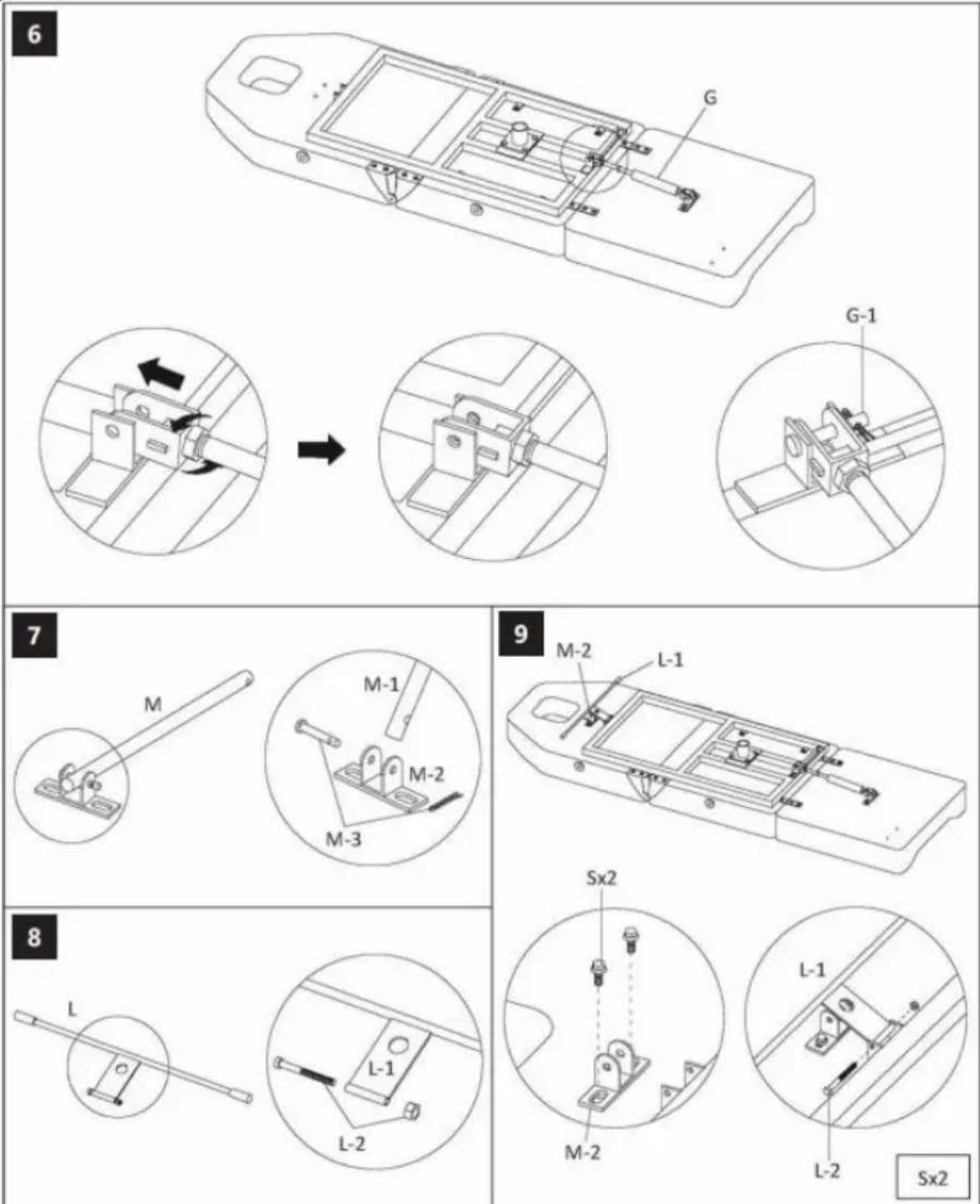
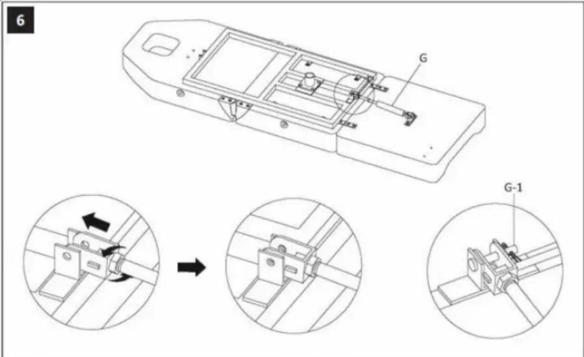
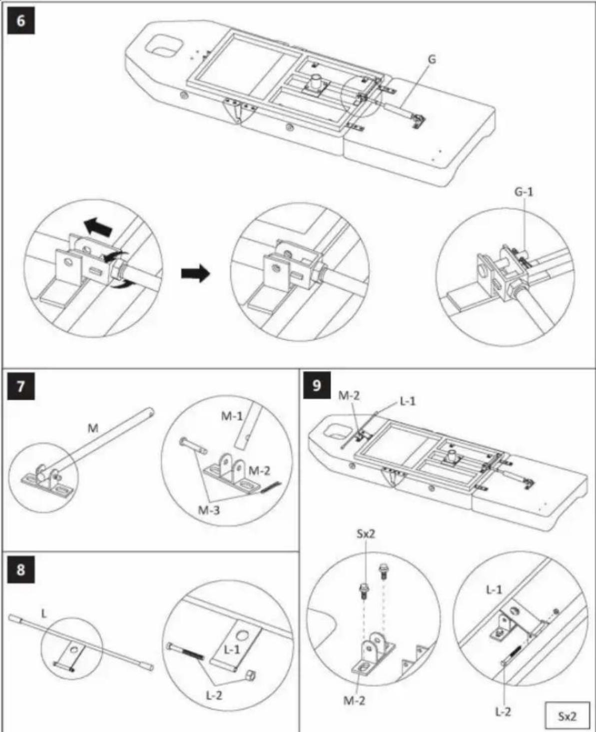
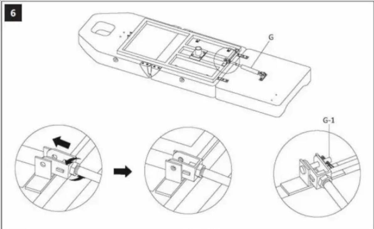
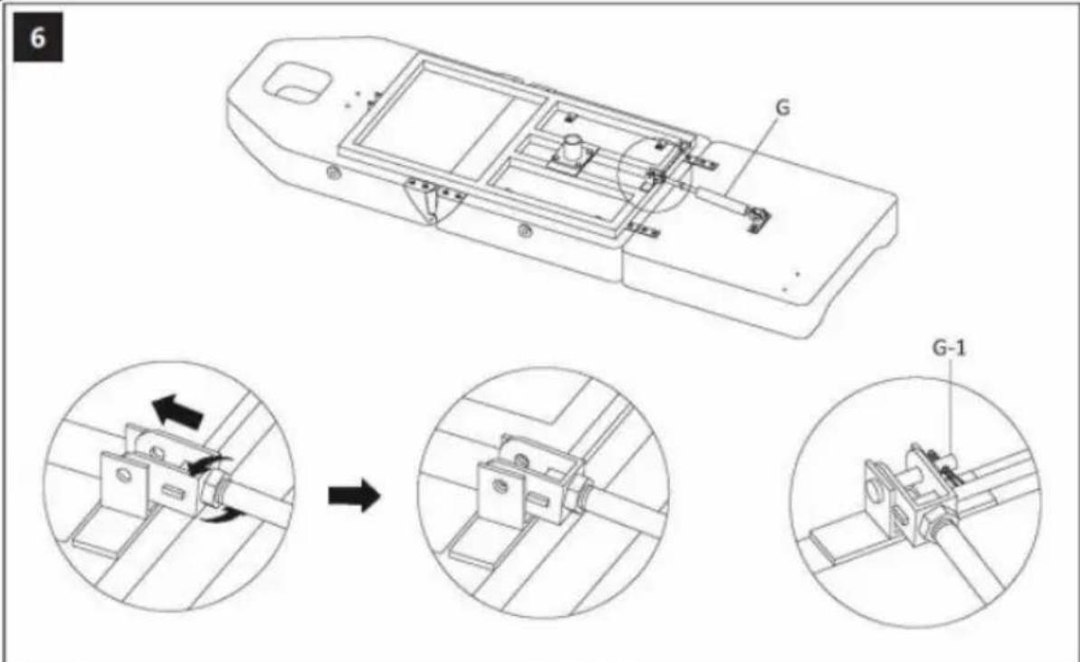
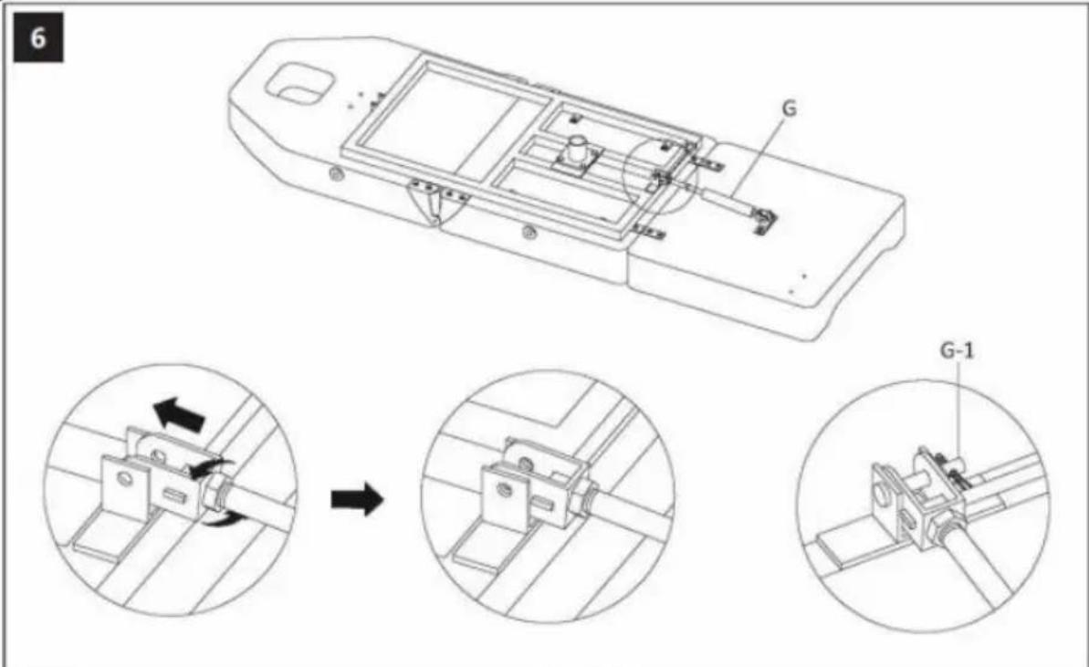
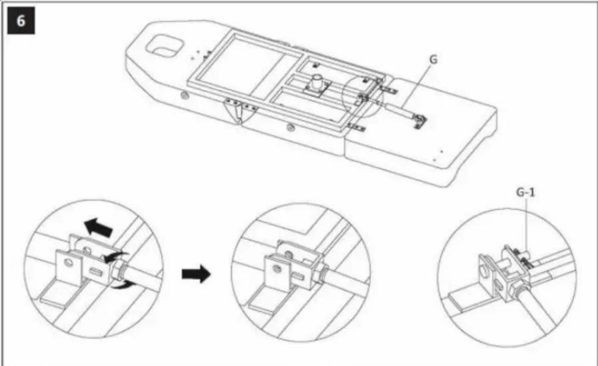
6 G G-1
text_image
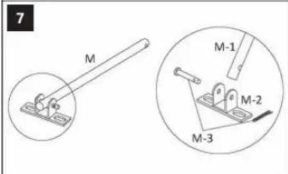
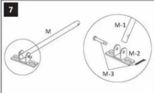
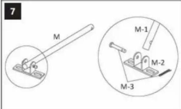
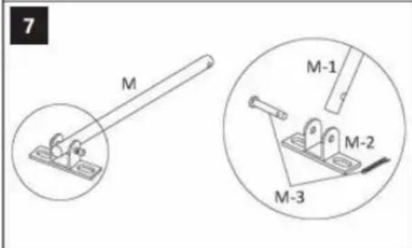
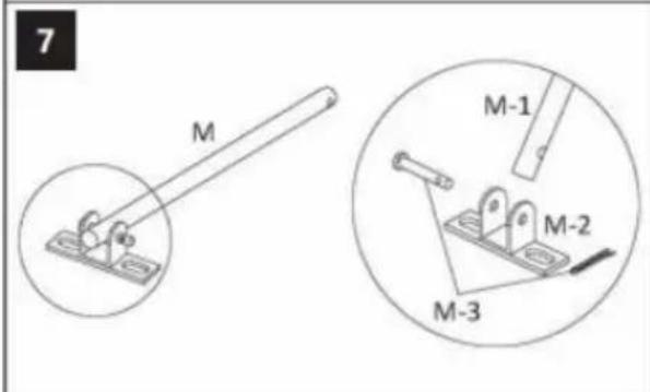
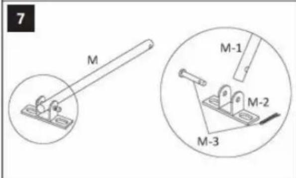
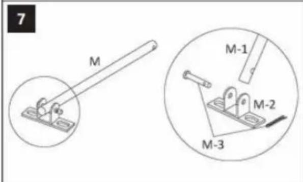
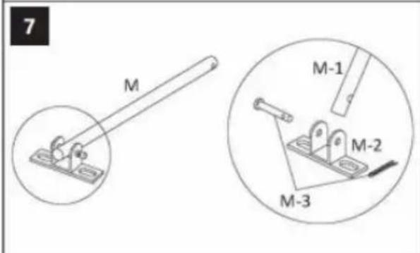
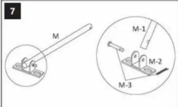
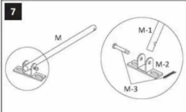
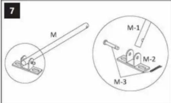
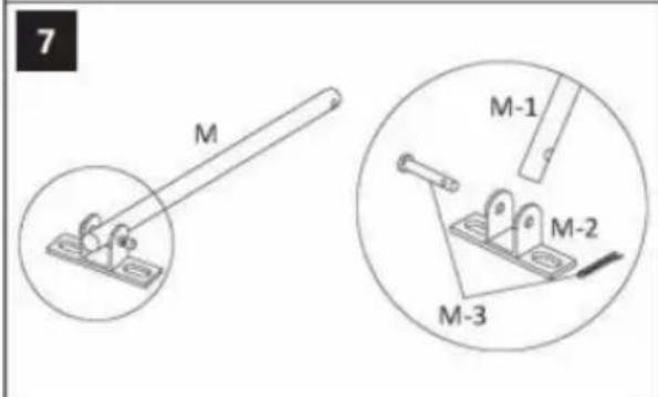
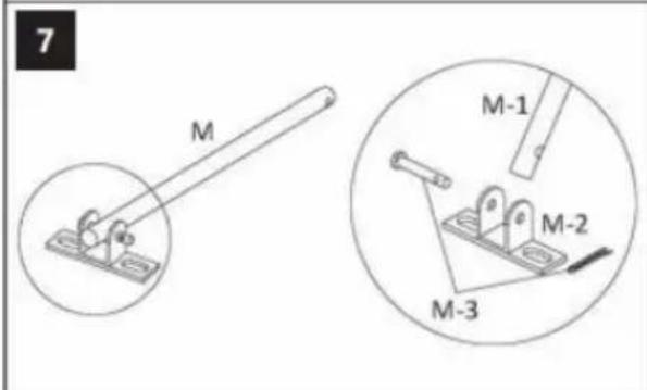
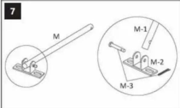
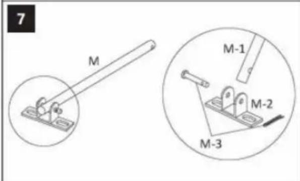
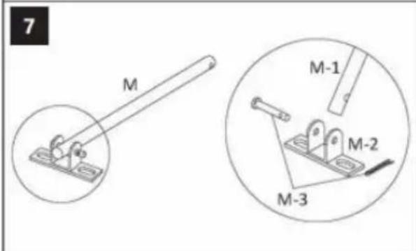
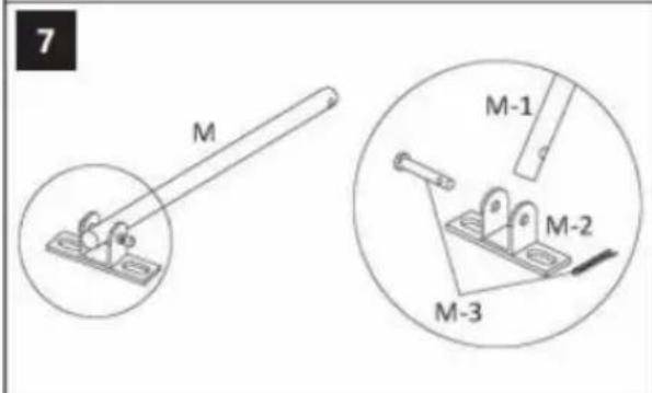
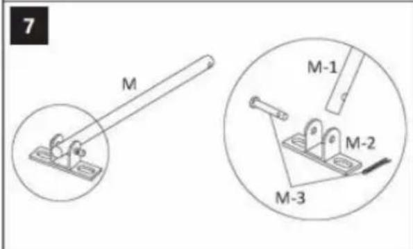
7 M M-1 M-2 M-3
text_image
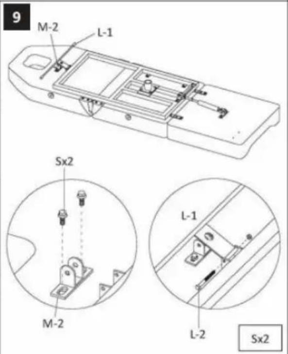
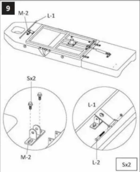
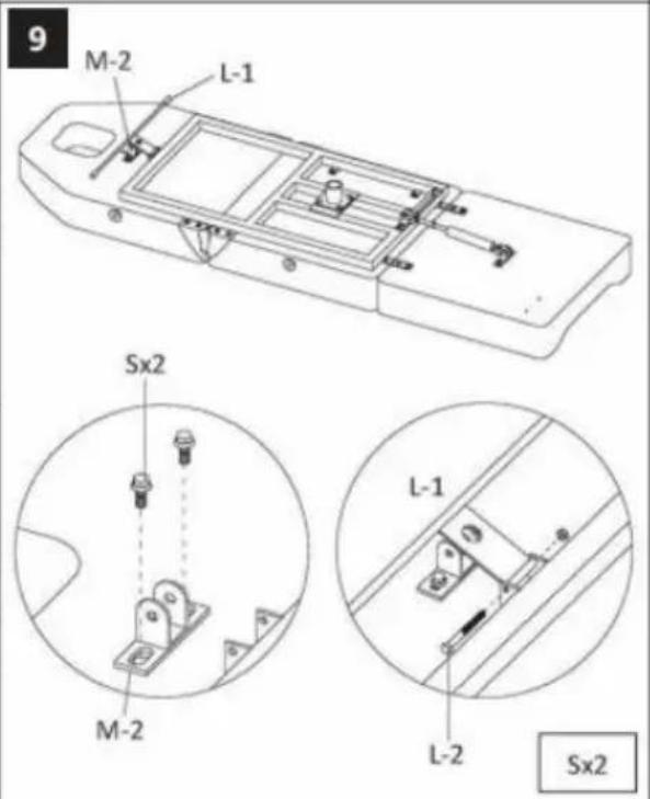
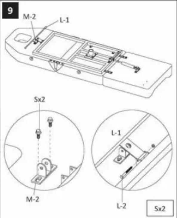
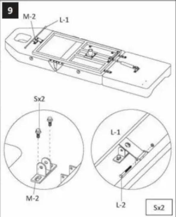
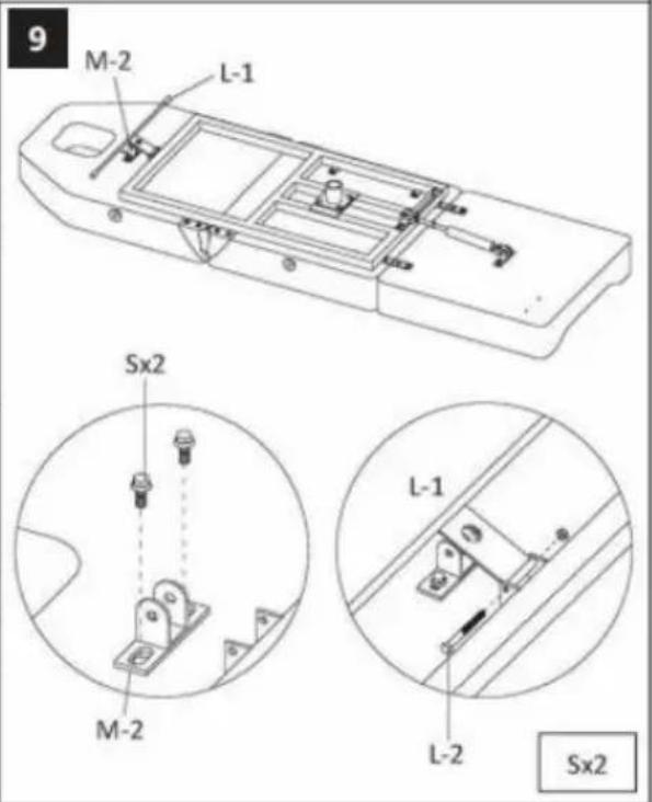
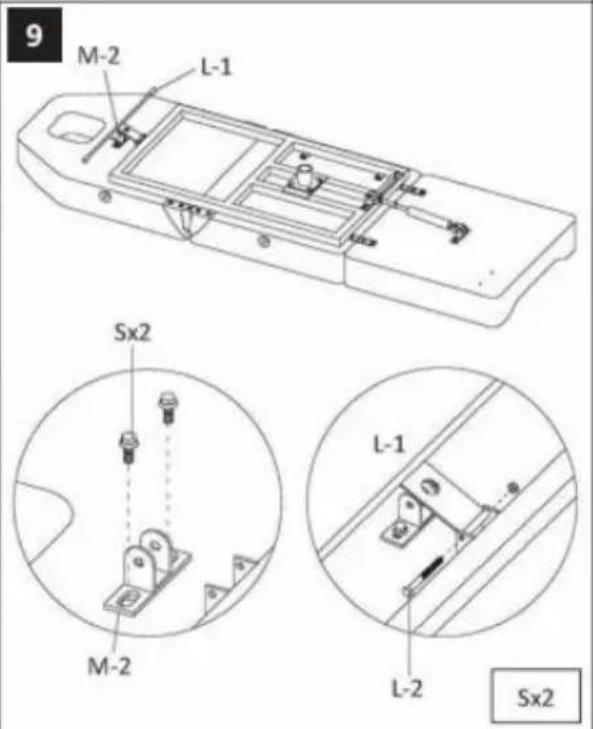
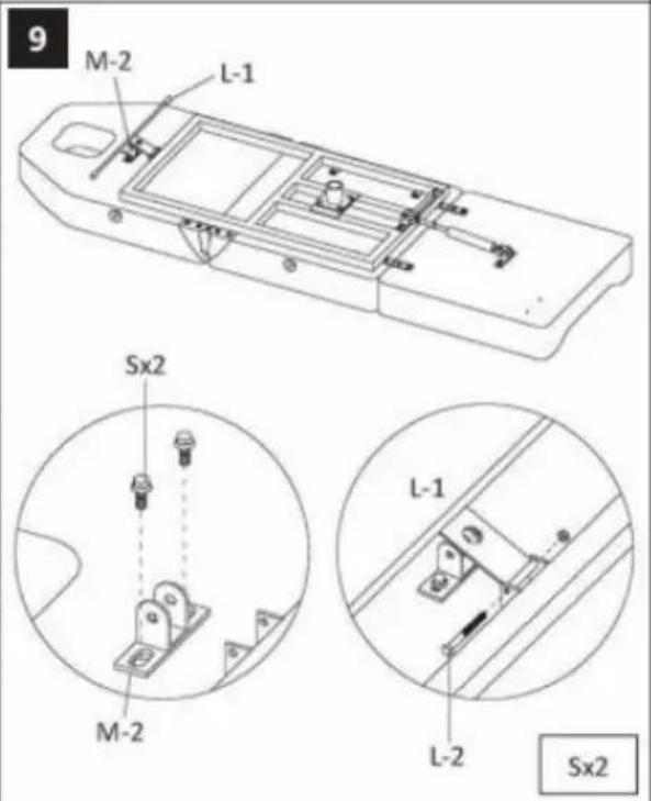
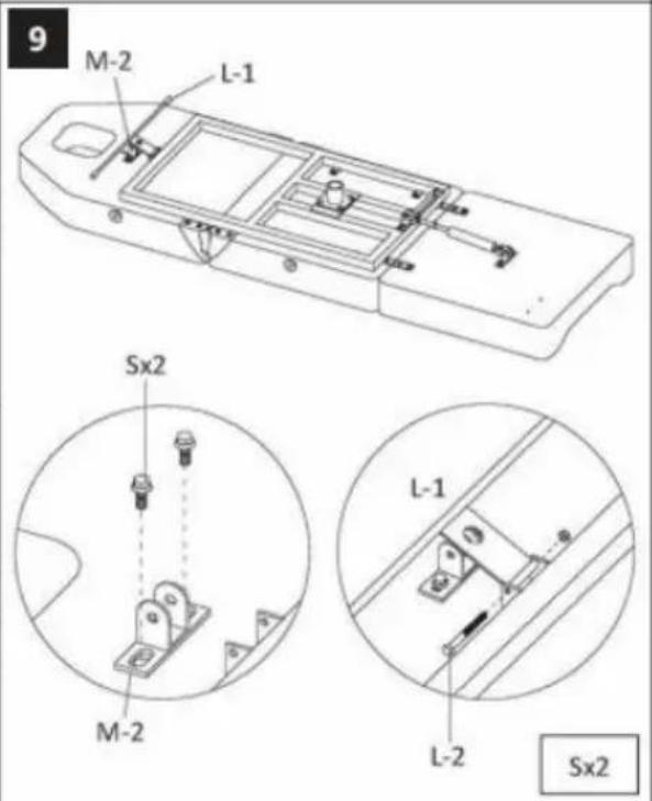
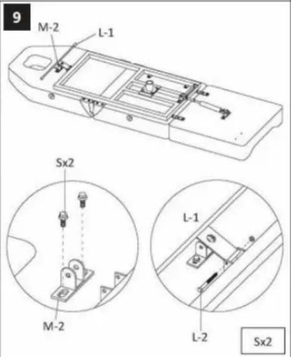
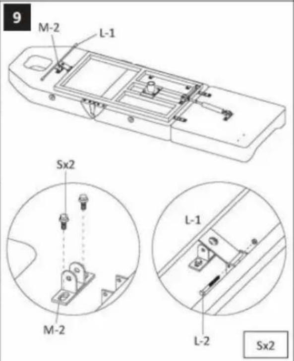
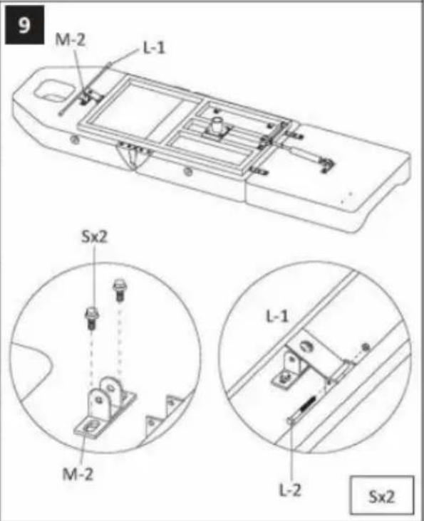
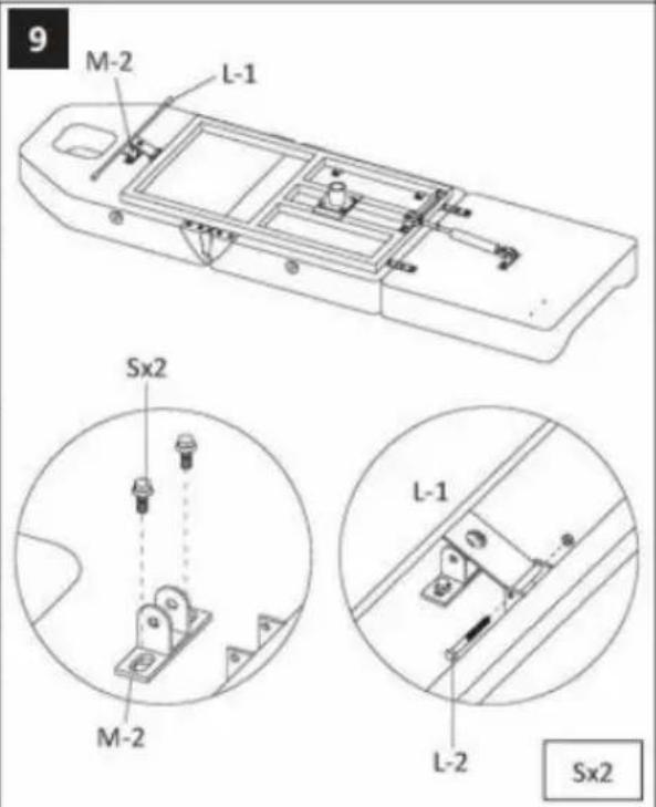
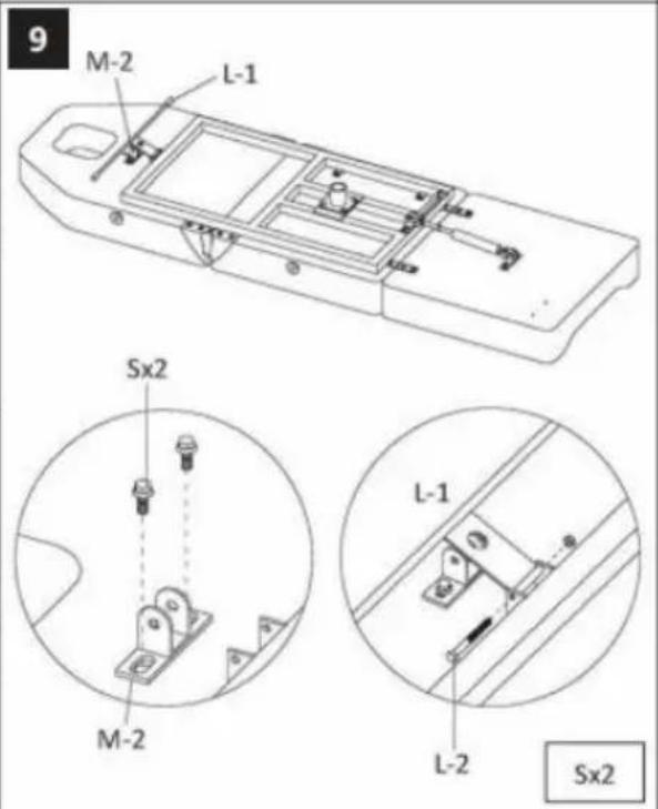
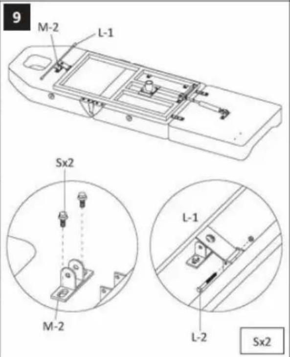
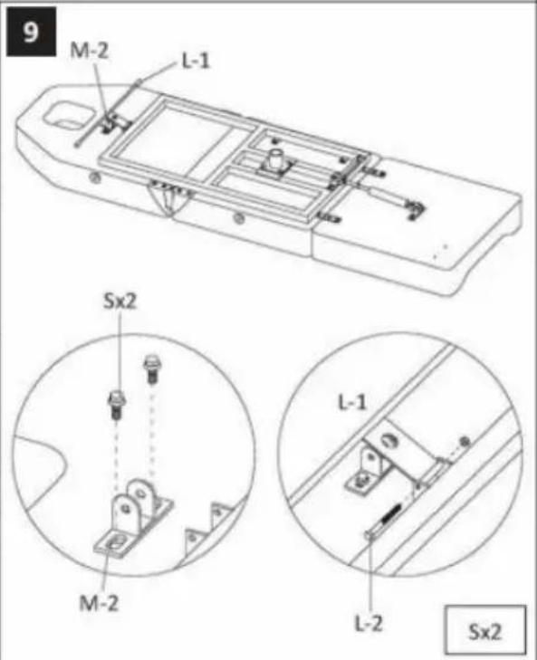
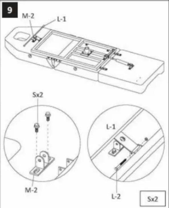
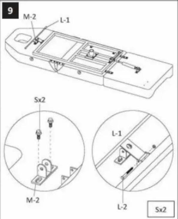
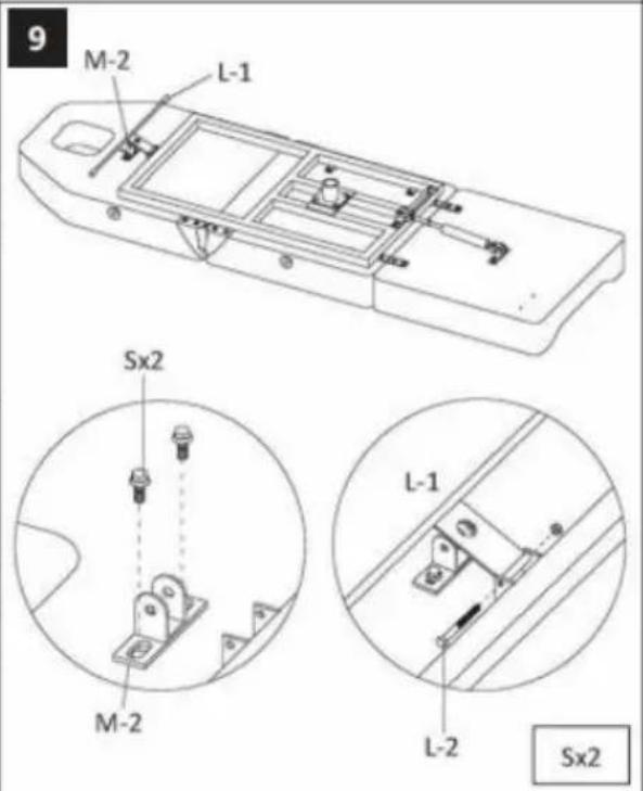
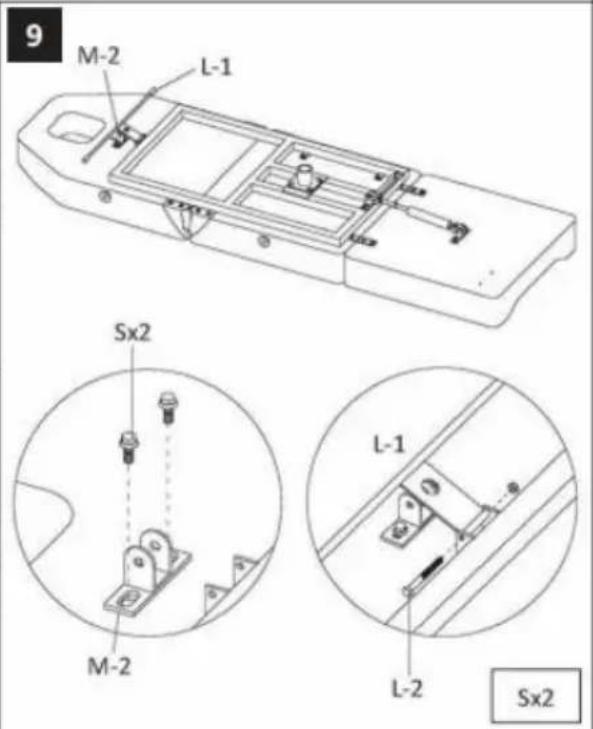
9 M-2 L-1 Sx2 M-2 L-1 L-2 Sx2
text_image
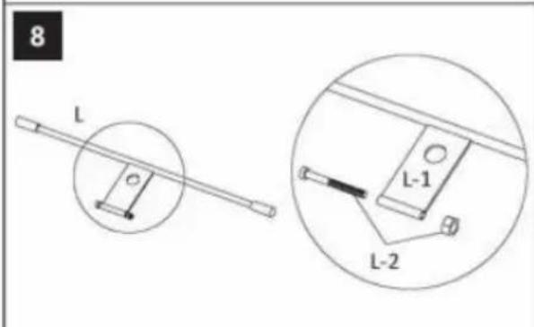
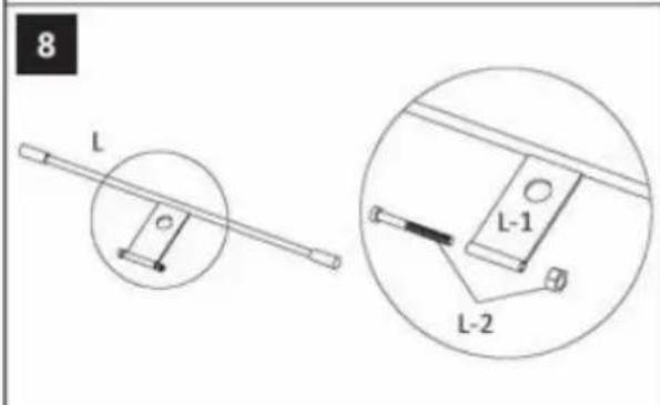
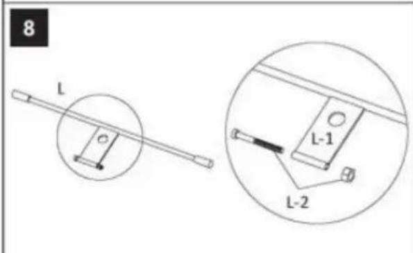
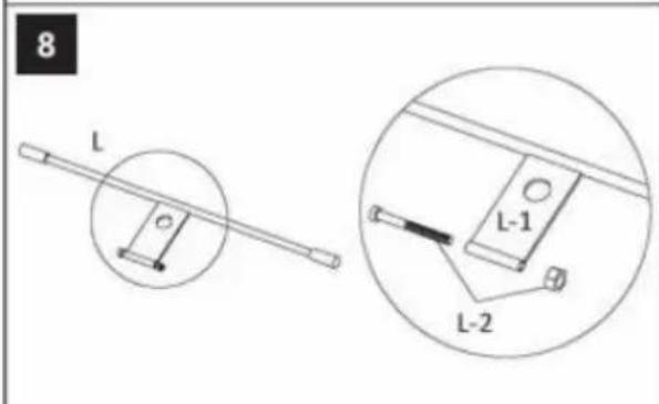
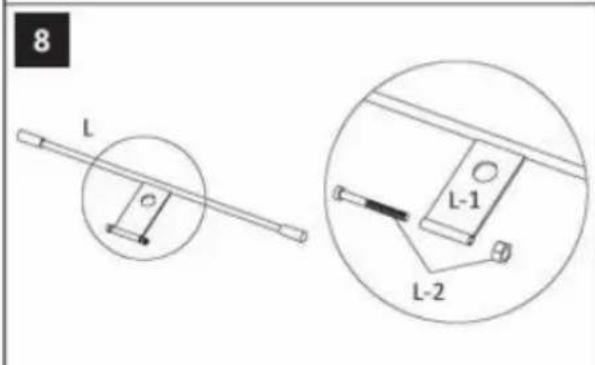
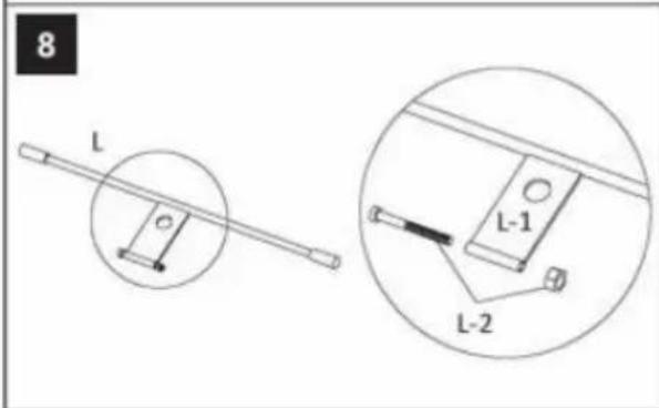
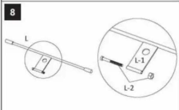
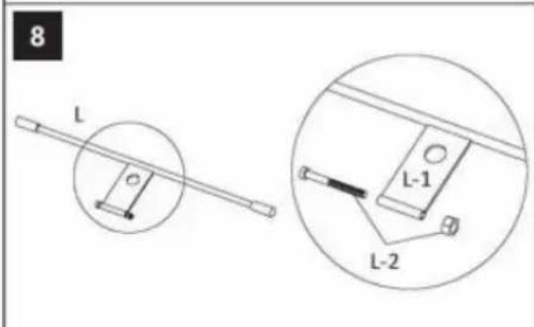
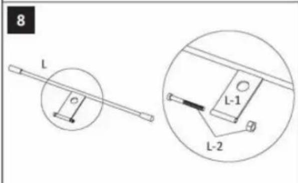
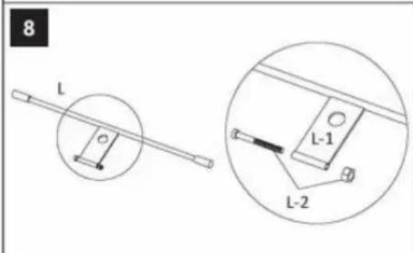
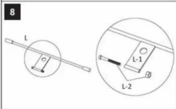
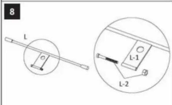
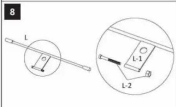
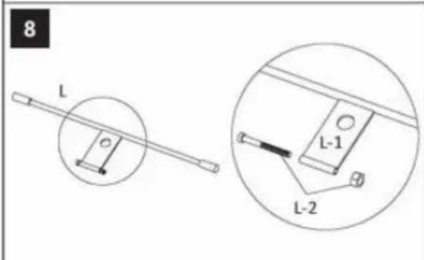
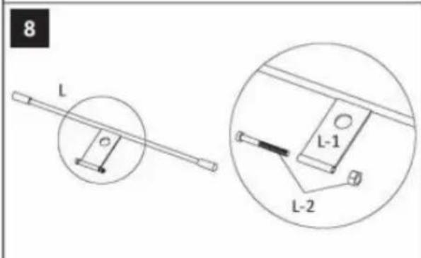
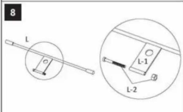
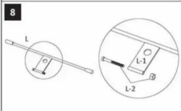
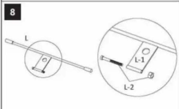
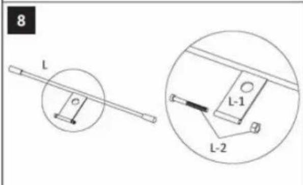
8 L L-1 L-2
text_image
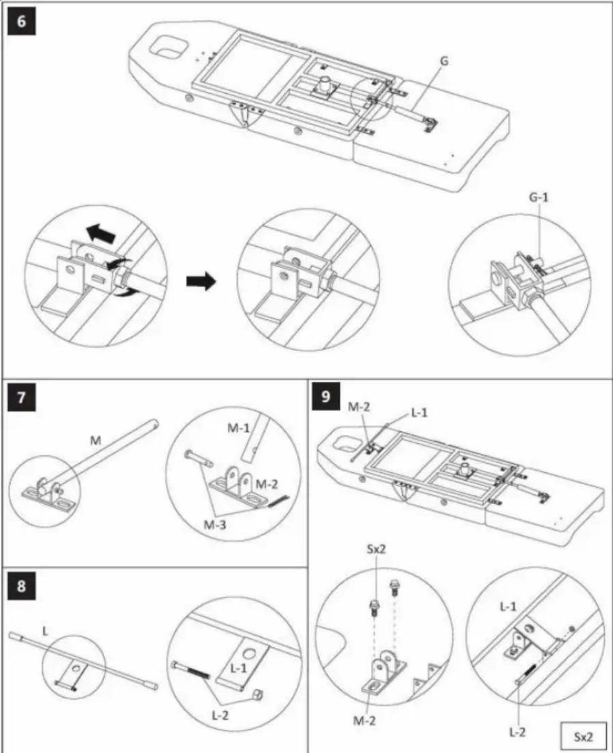
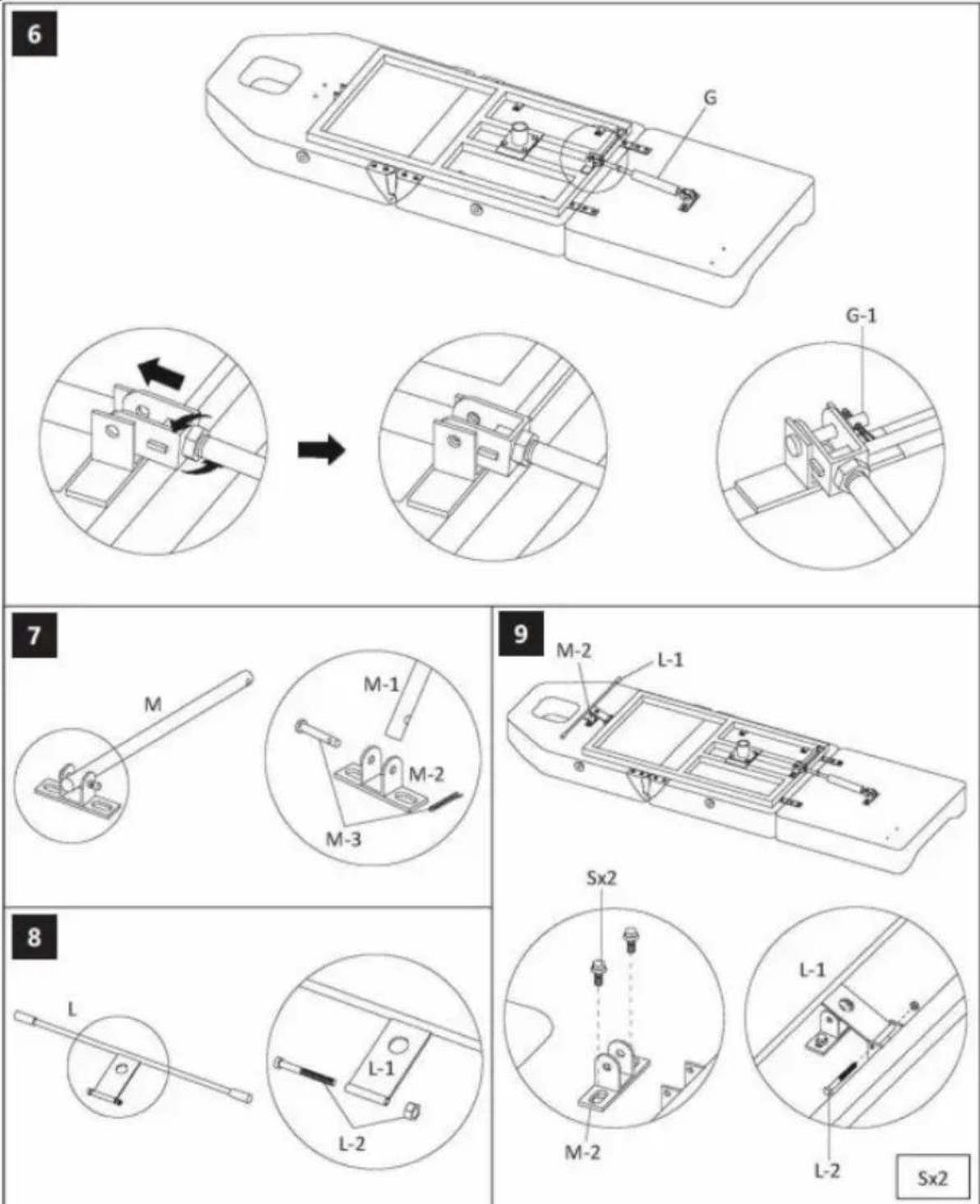
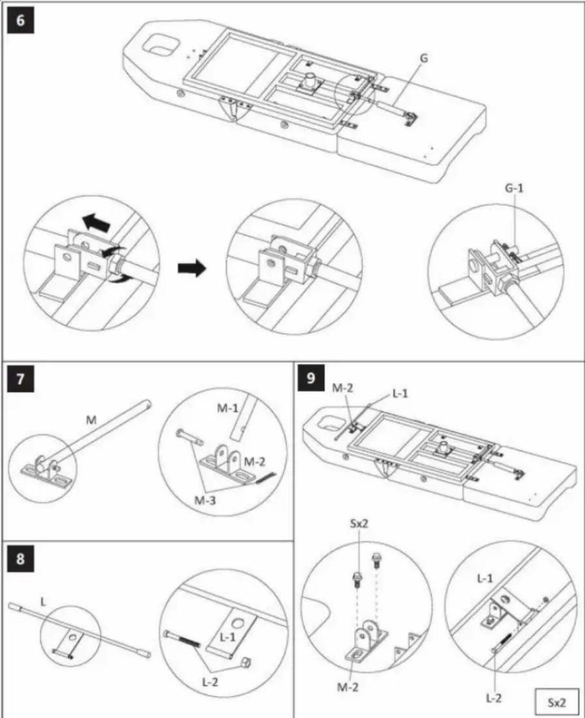
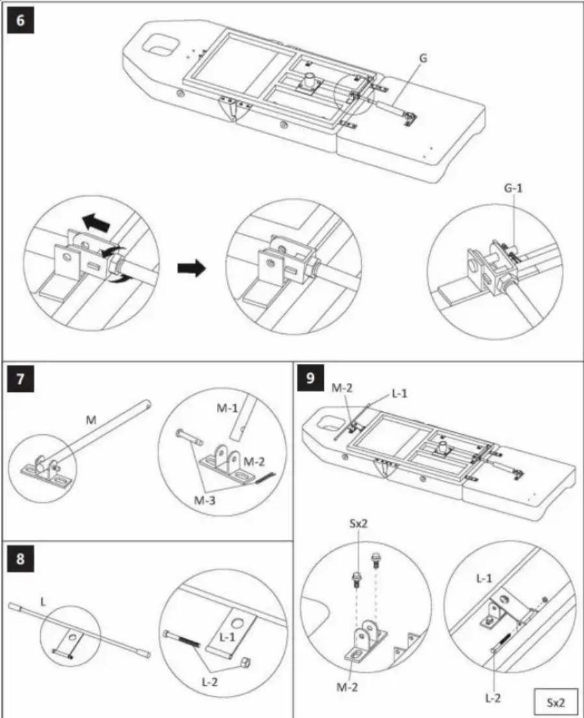
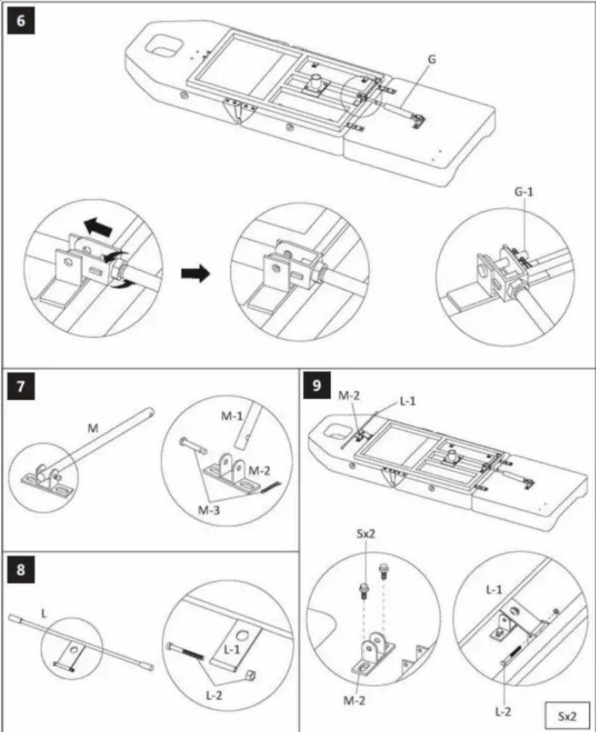
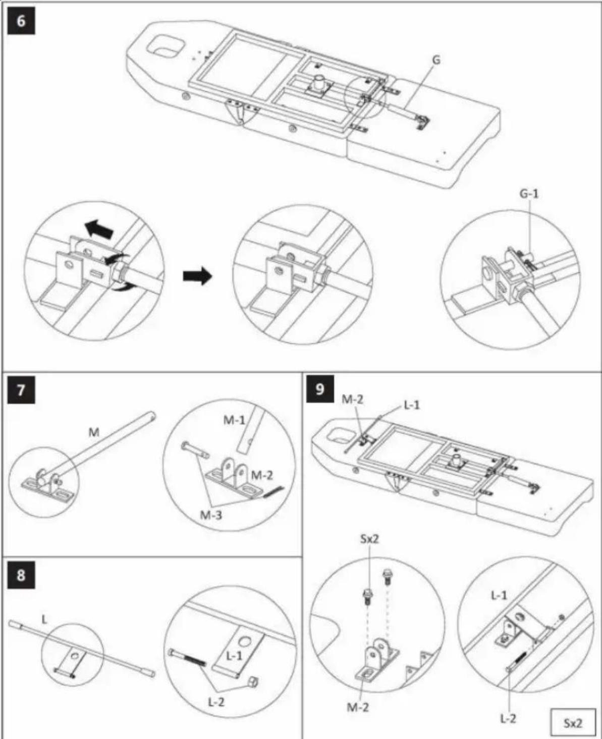
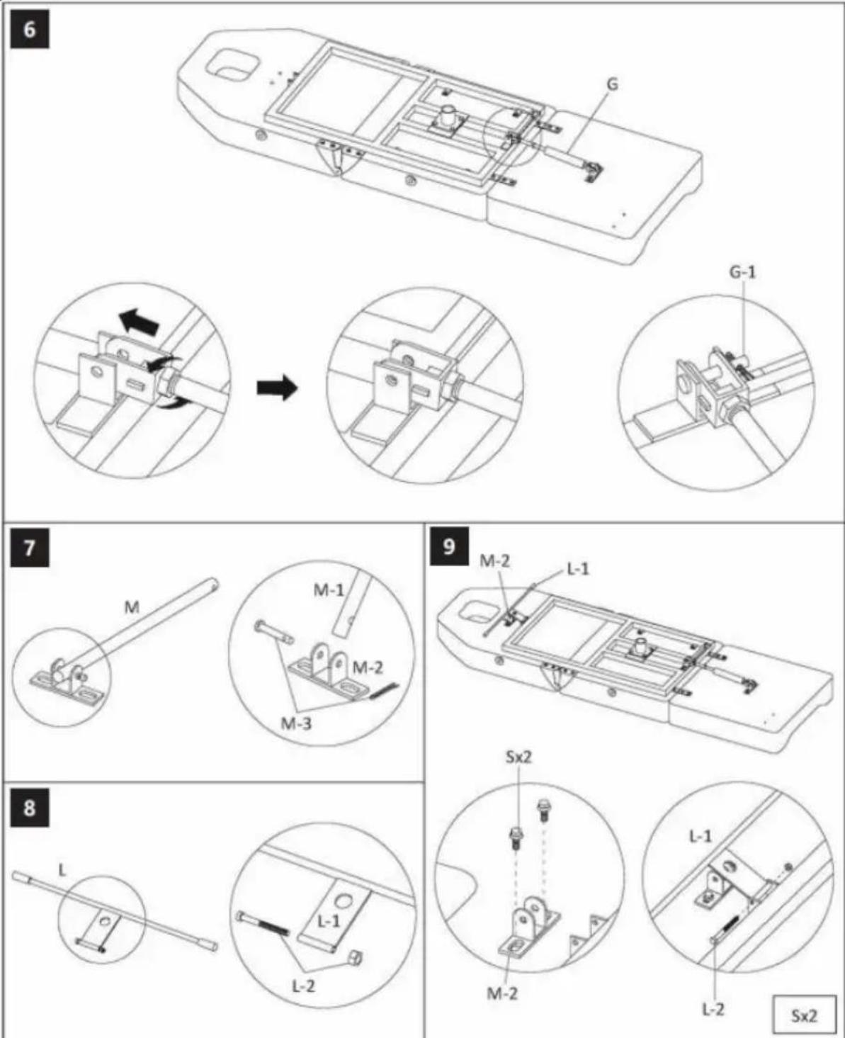
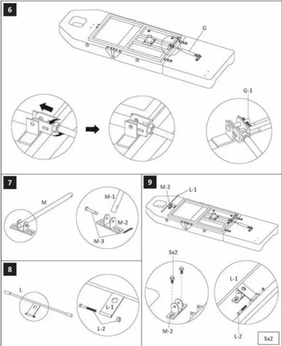
6 G G-1 7 M M-1 M-2 M-3 9 M-2 L-1 Sx2 8 L L-1 L-2 L-1 L-2 Sx2
text_image
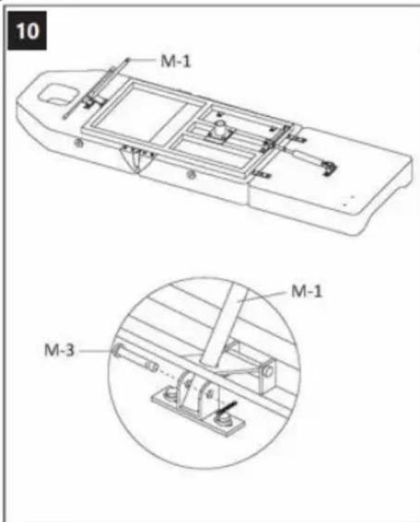
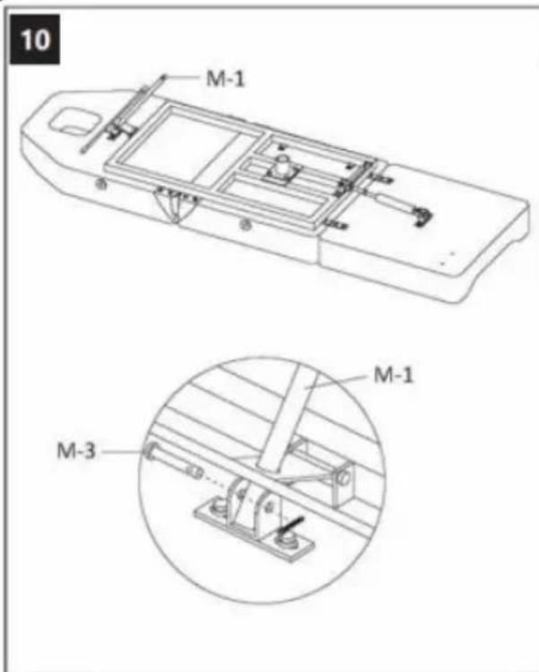
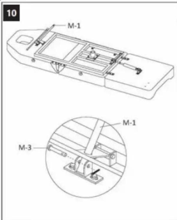
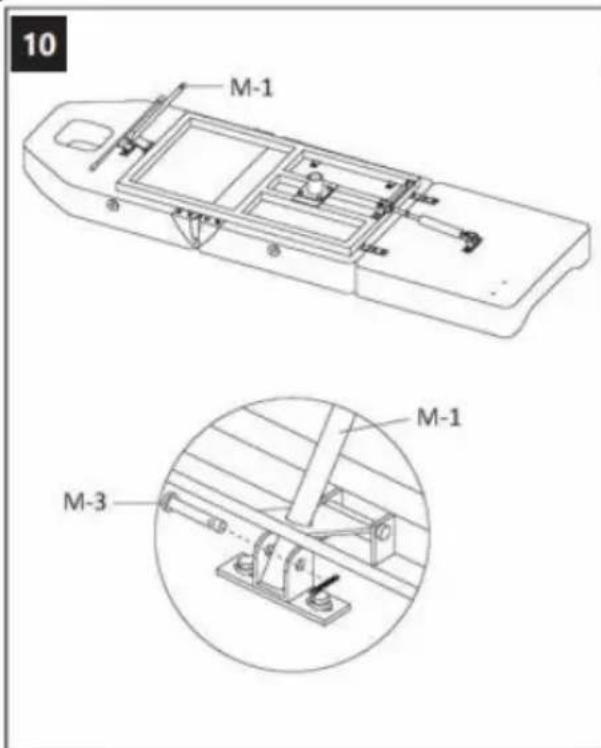
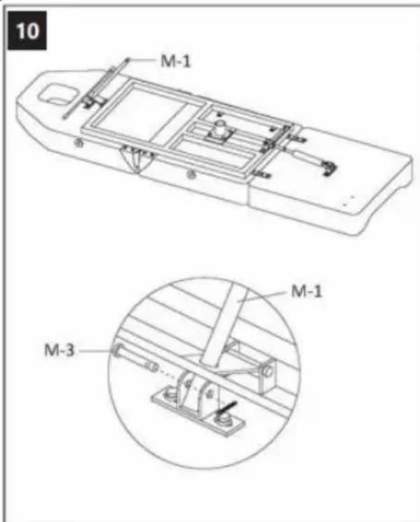
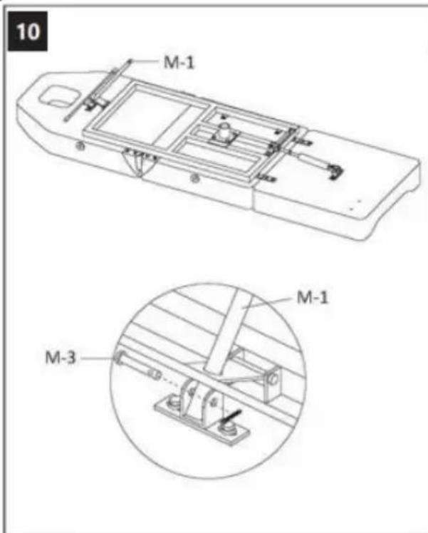
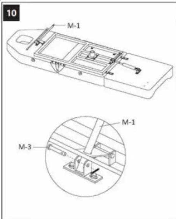
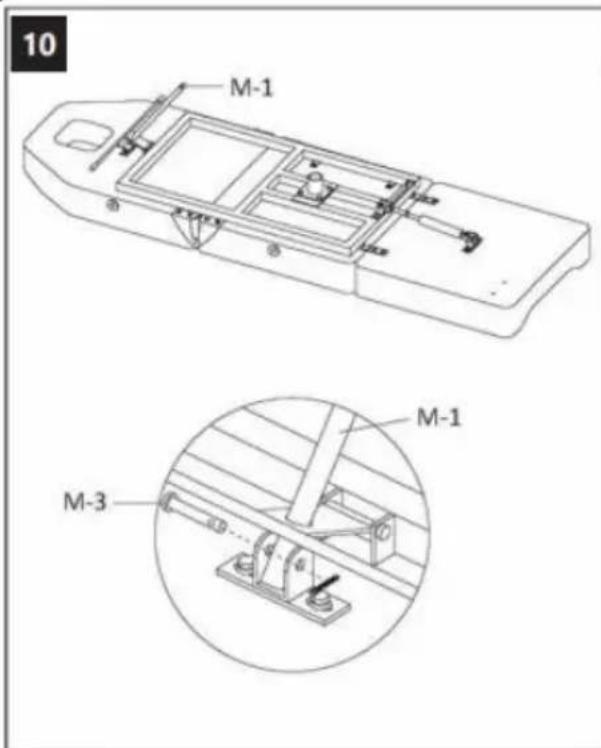
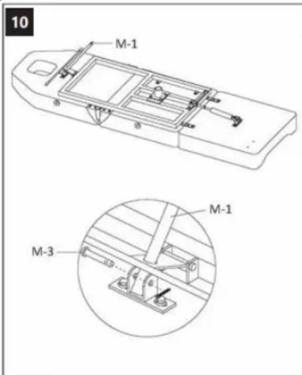
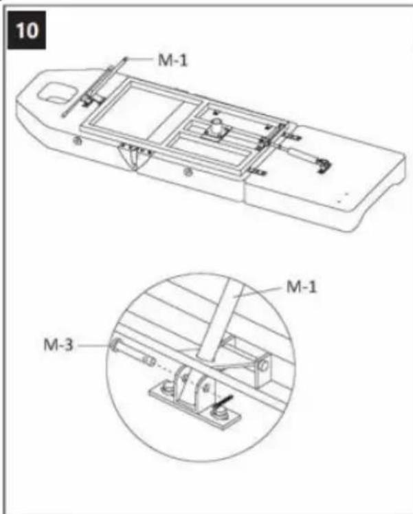
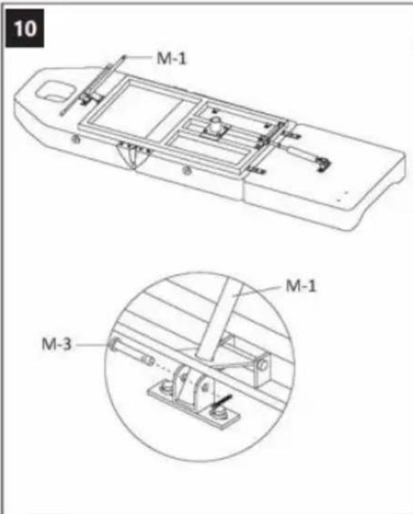
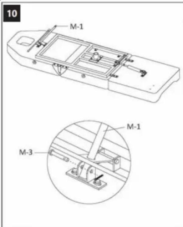
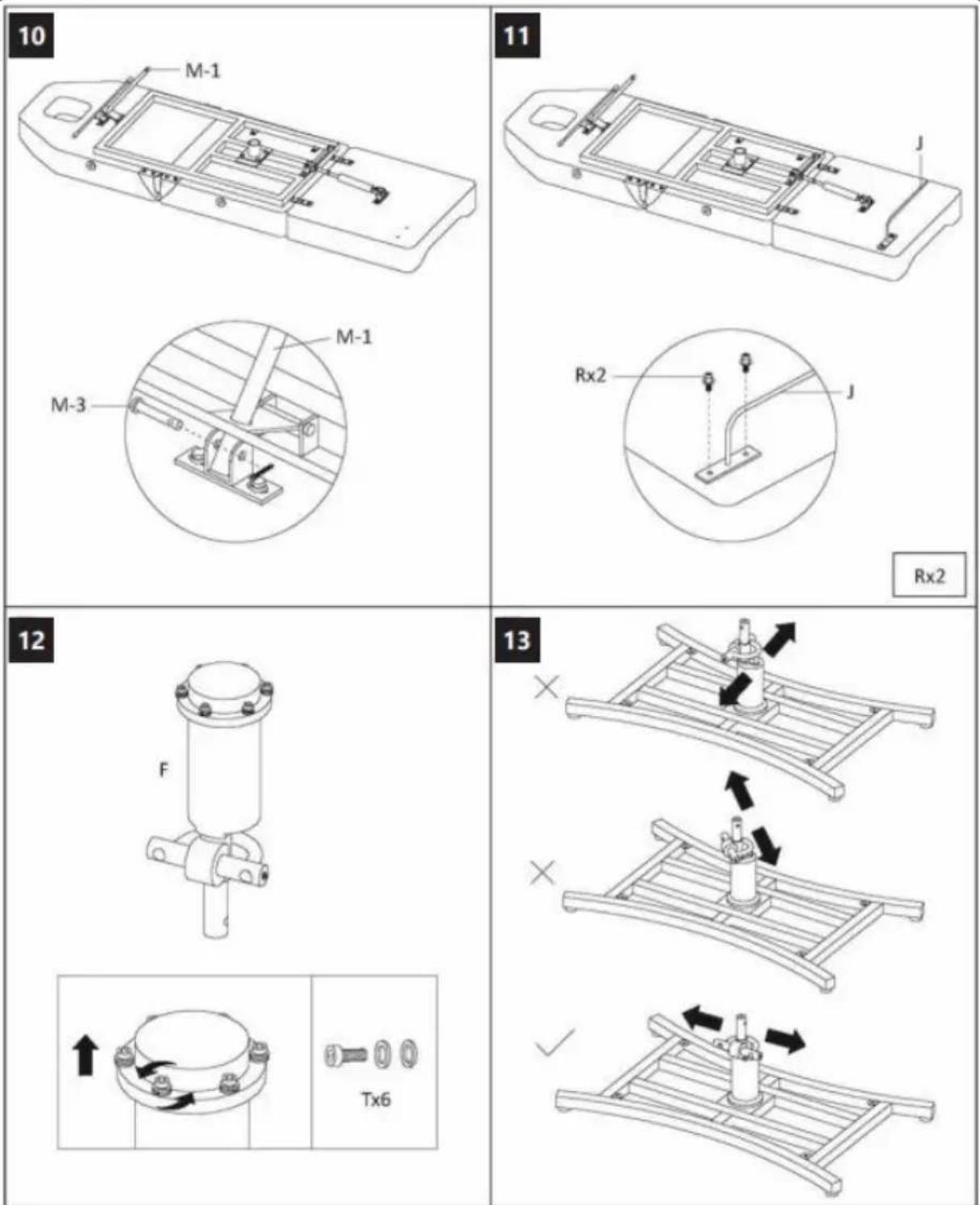
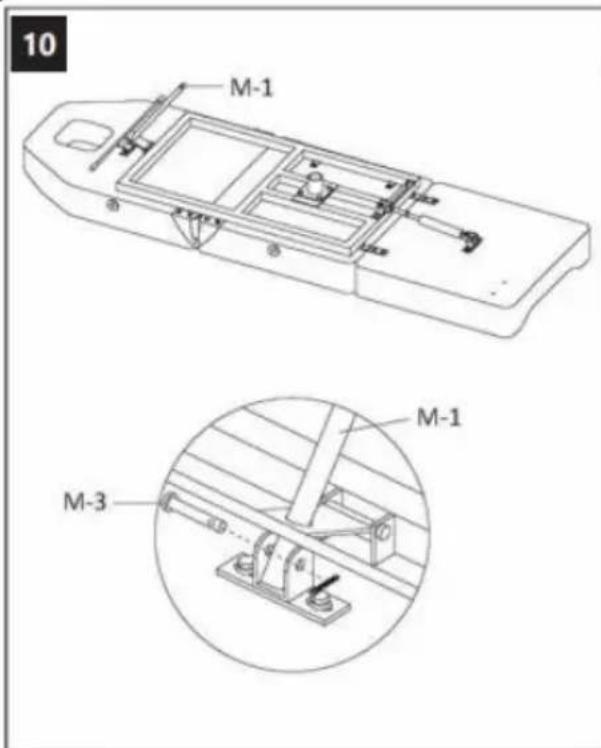
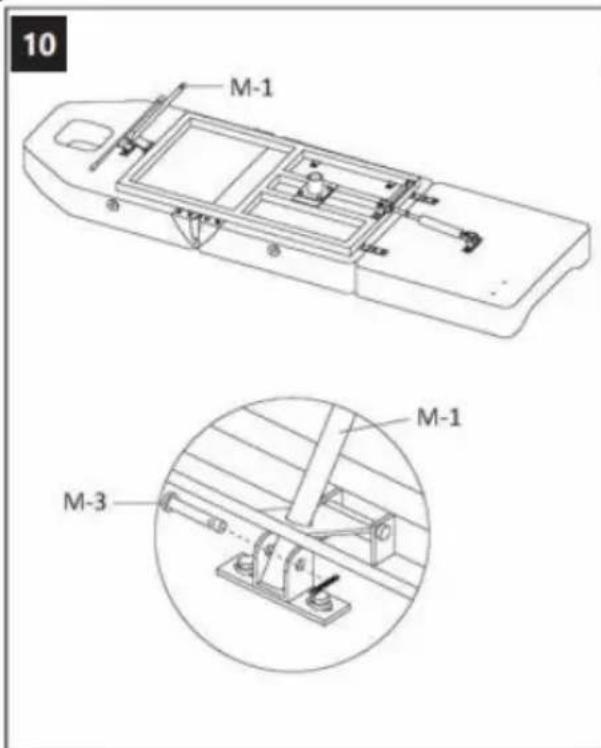
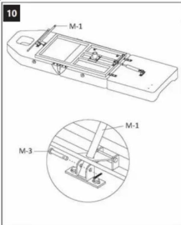
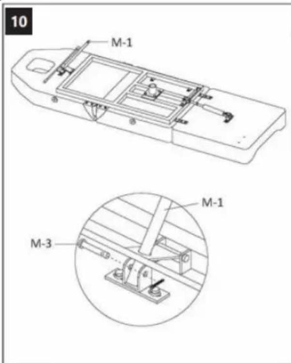
10 M-1 M-1 M-3
text_image
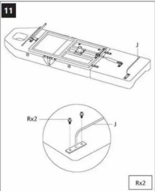
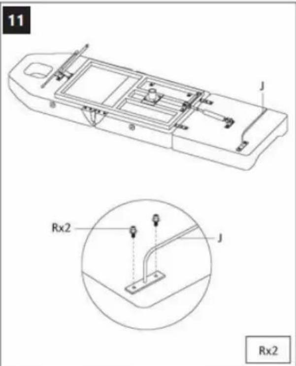
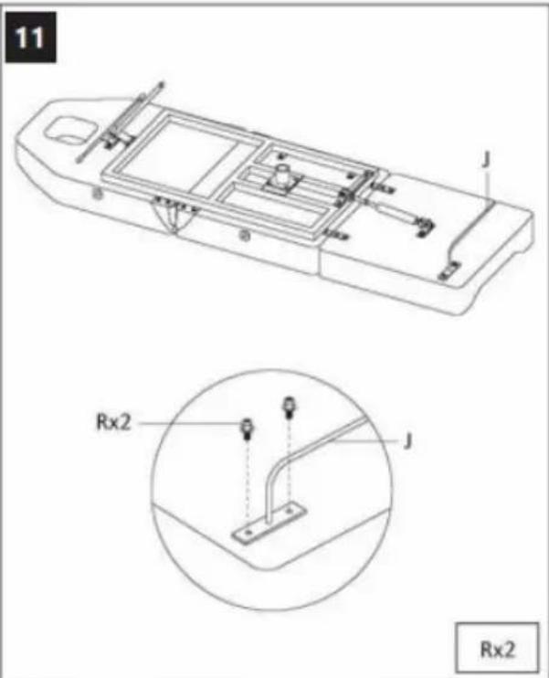
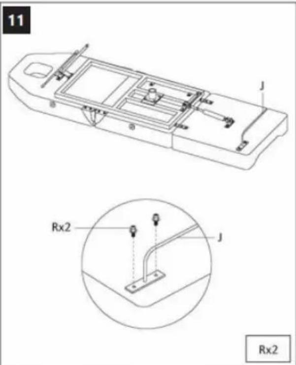
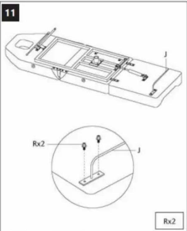
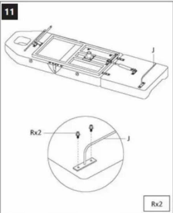
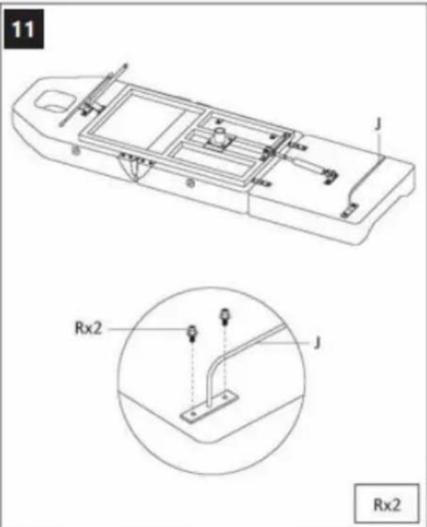
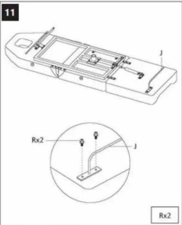
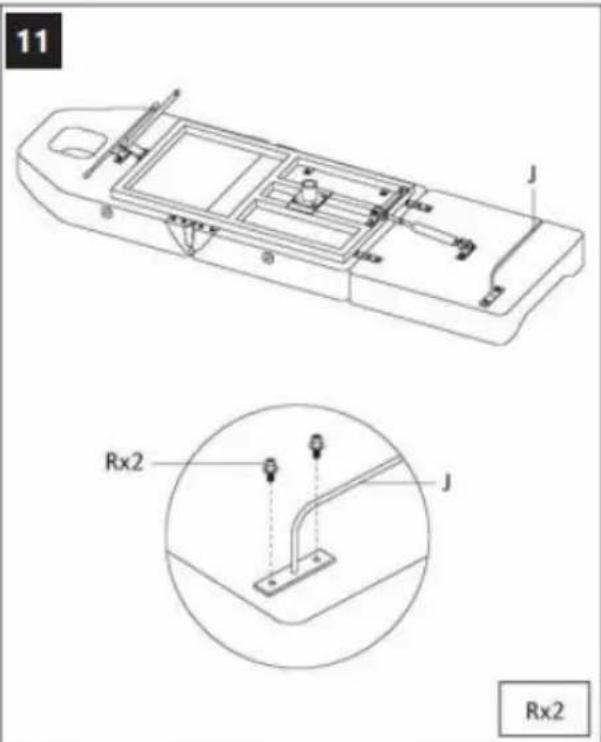
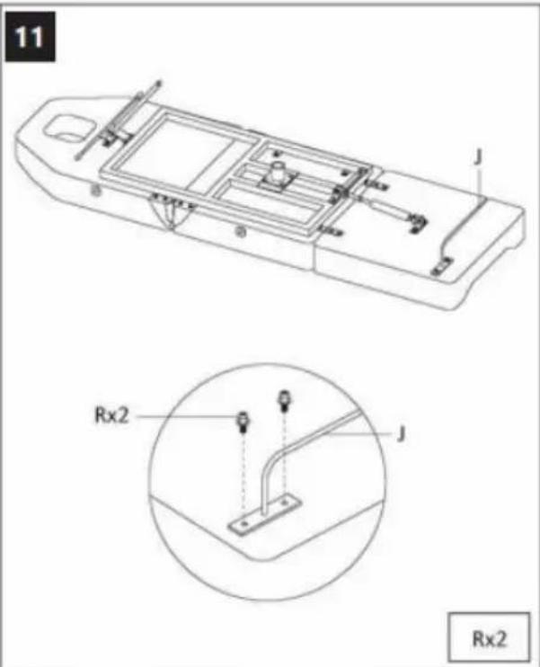
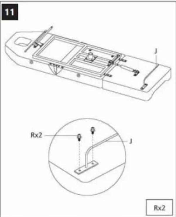
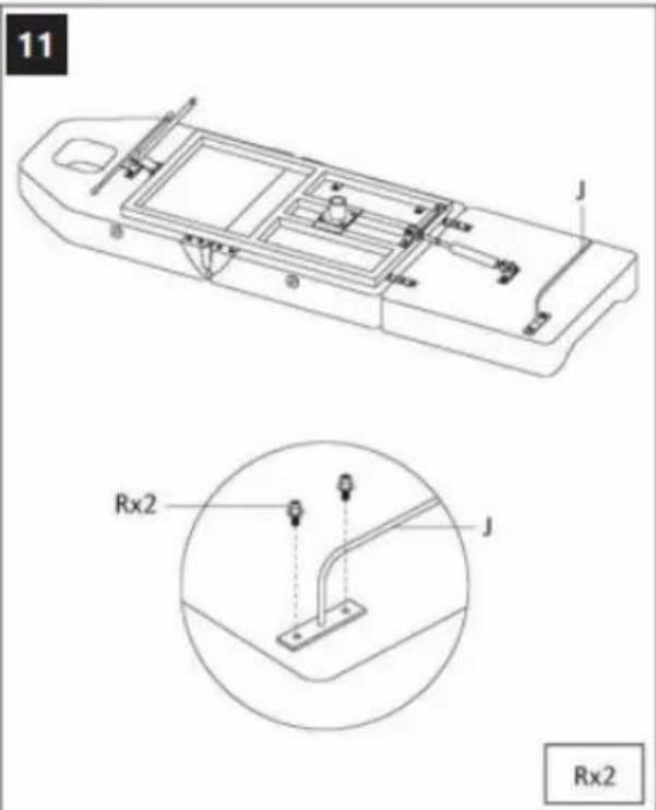
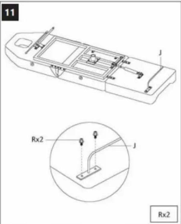
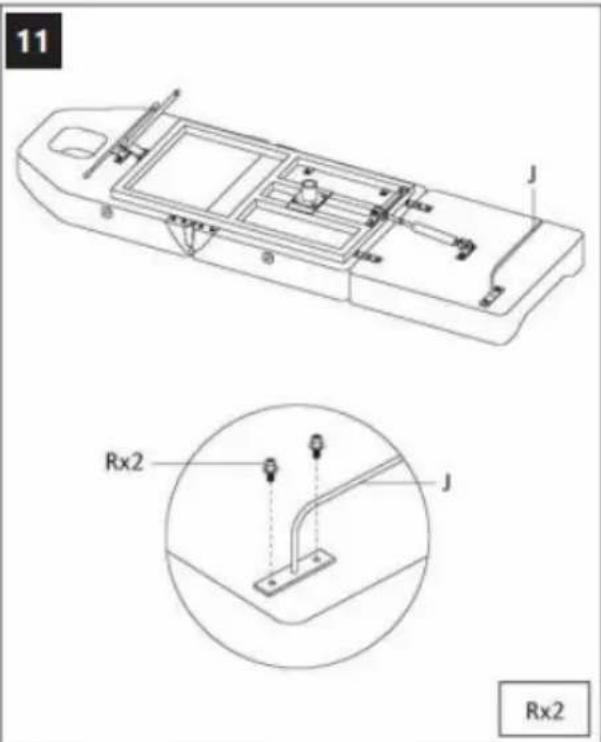
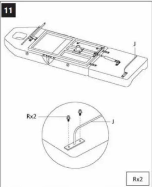
11 J Rx2 J Rx2
text_image
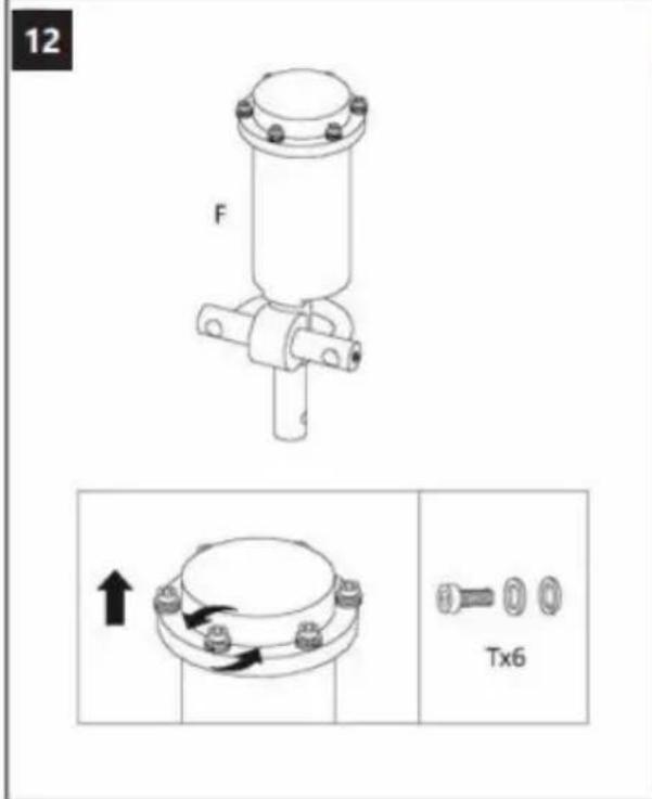
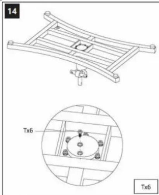
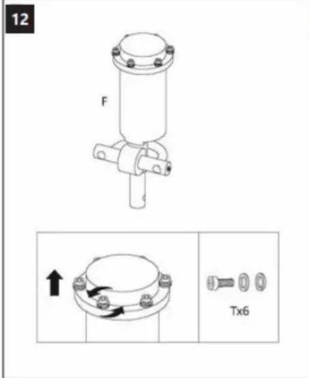
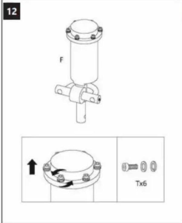
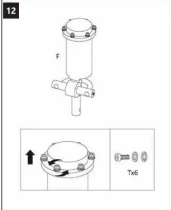
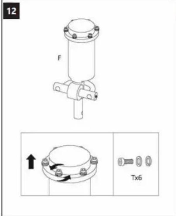
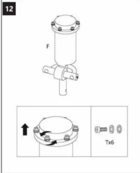
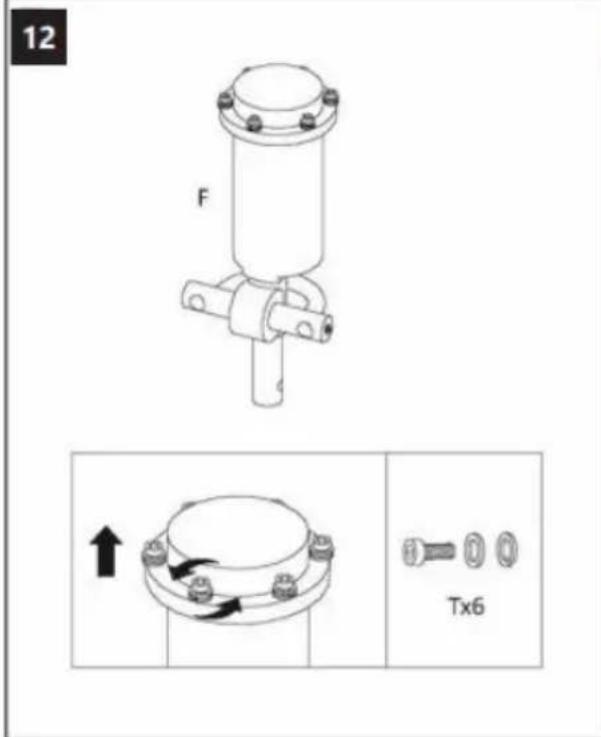
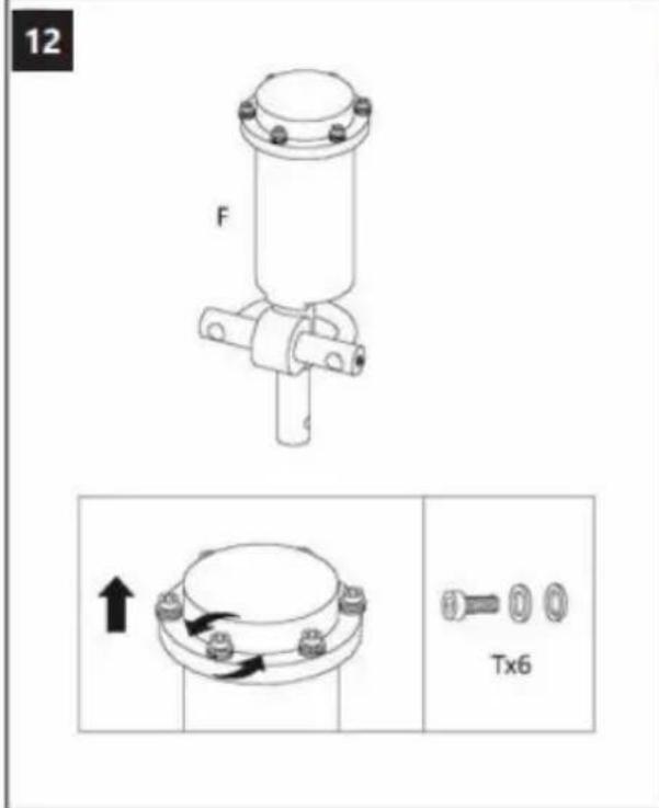
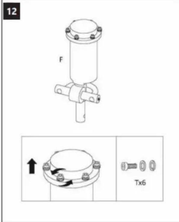
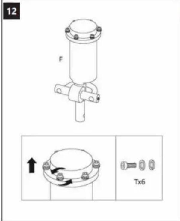
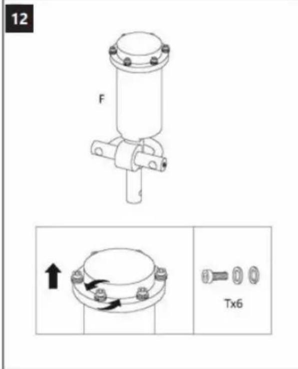
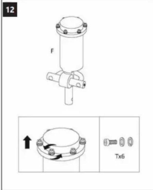
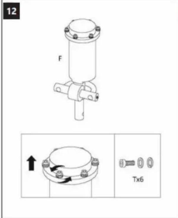
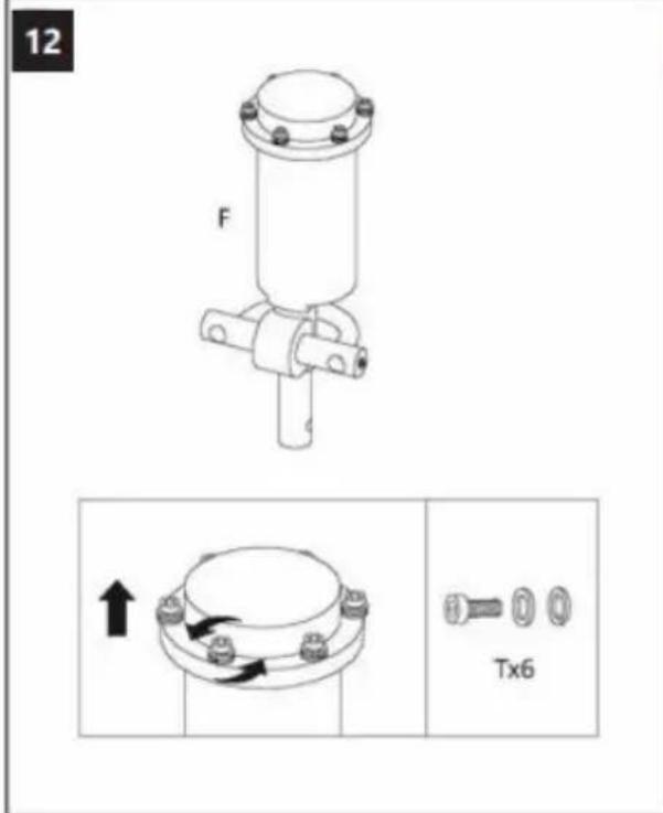
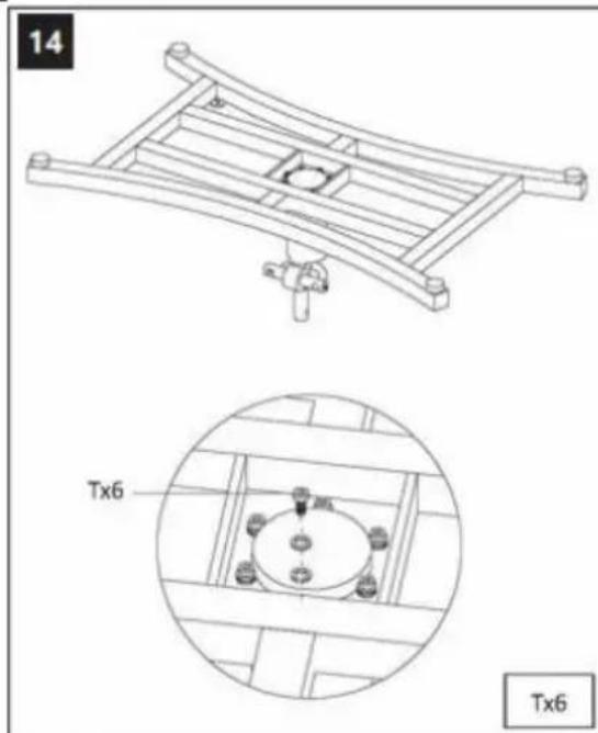
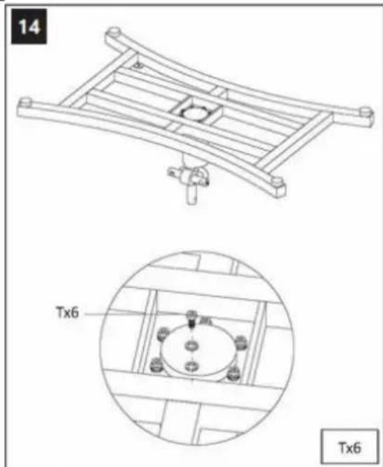
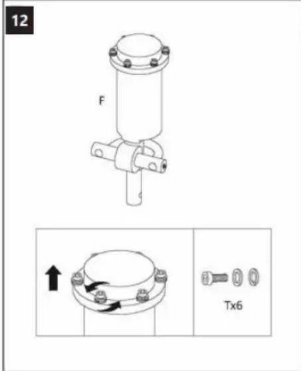
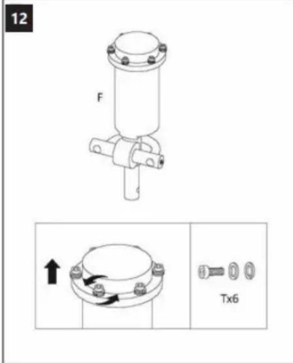
12 F Tx6
text_image
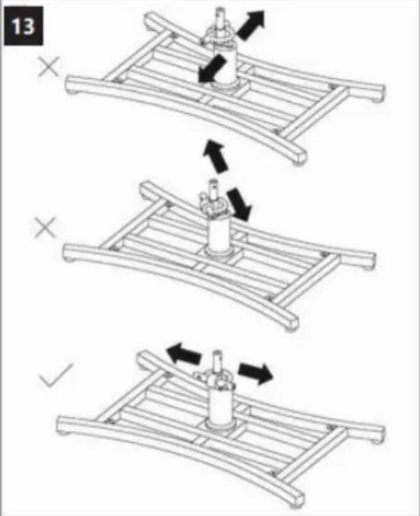
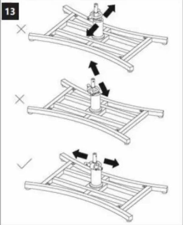
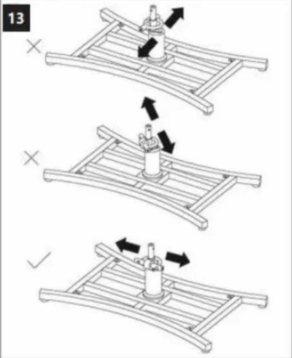
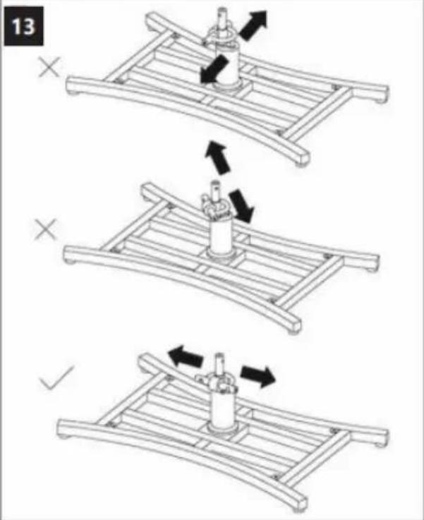
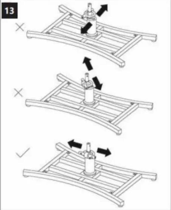
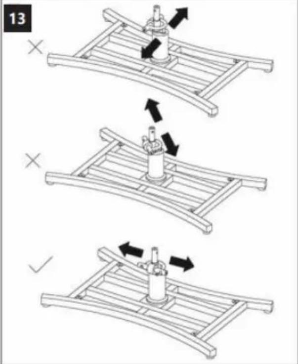
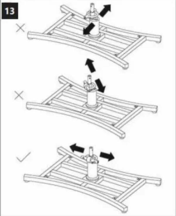
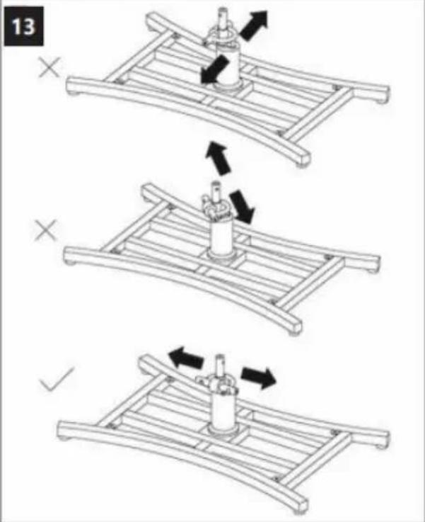
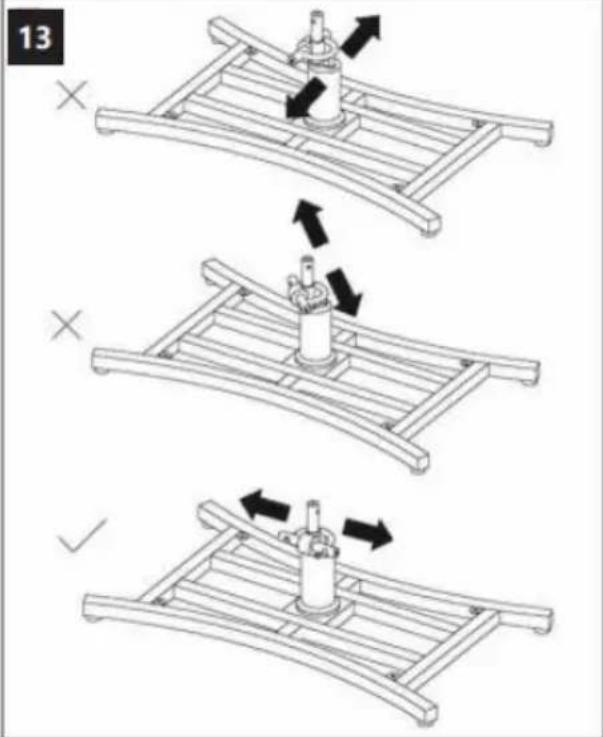
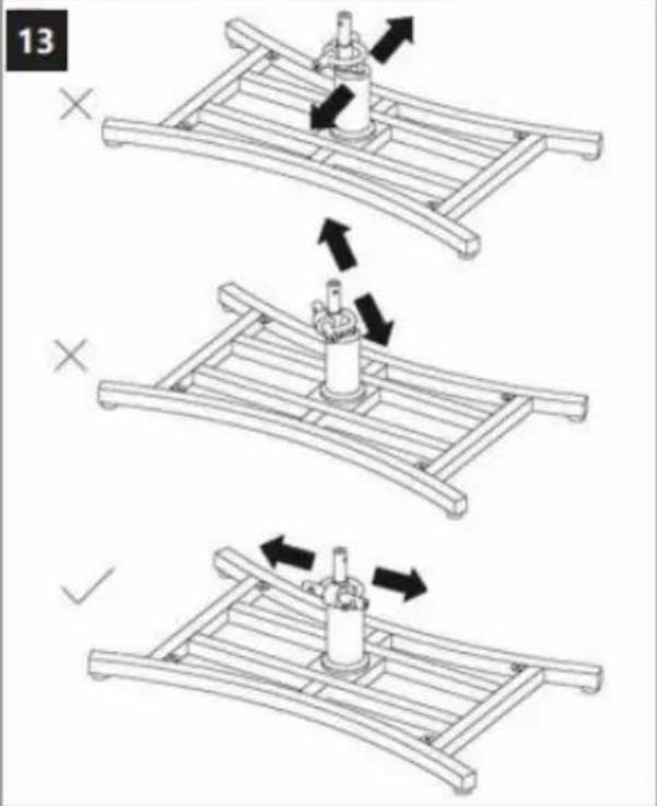
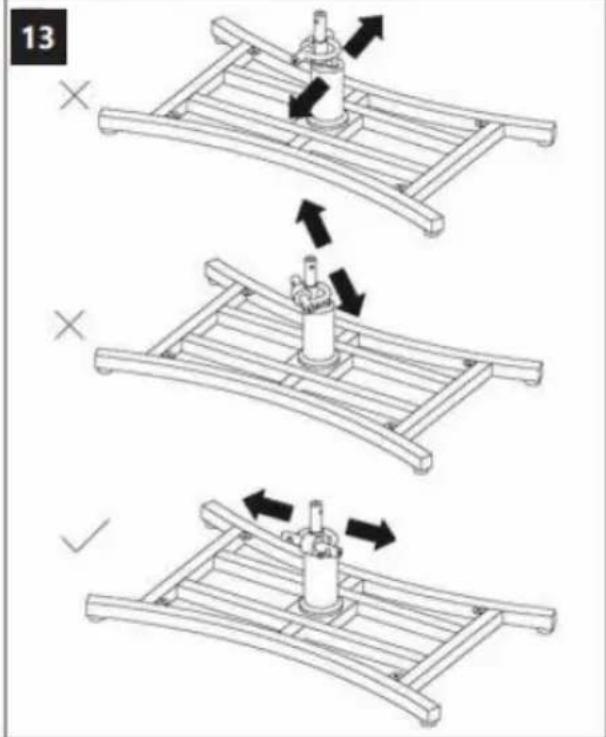
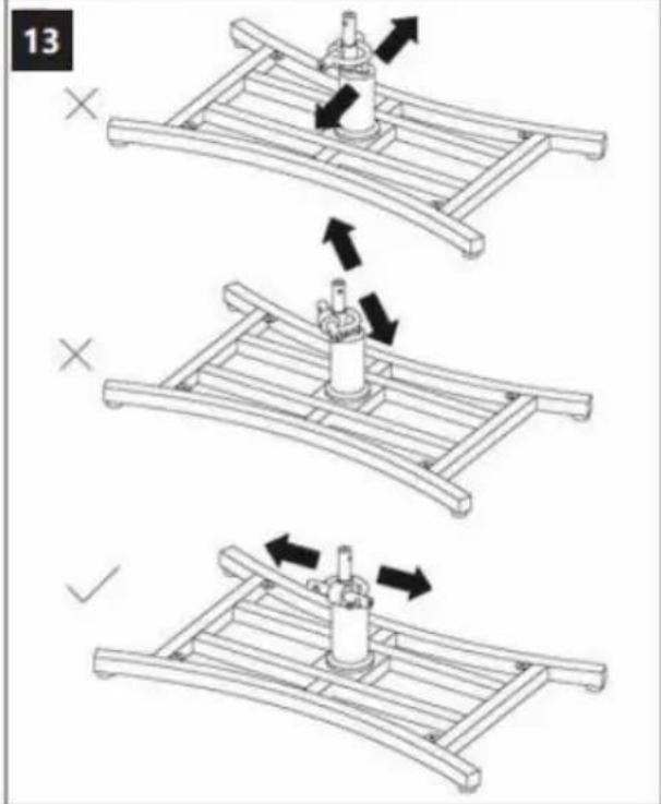
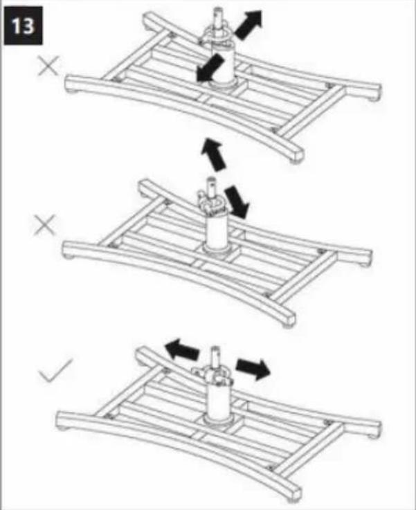
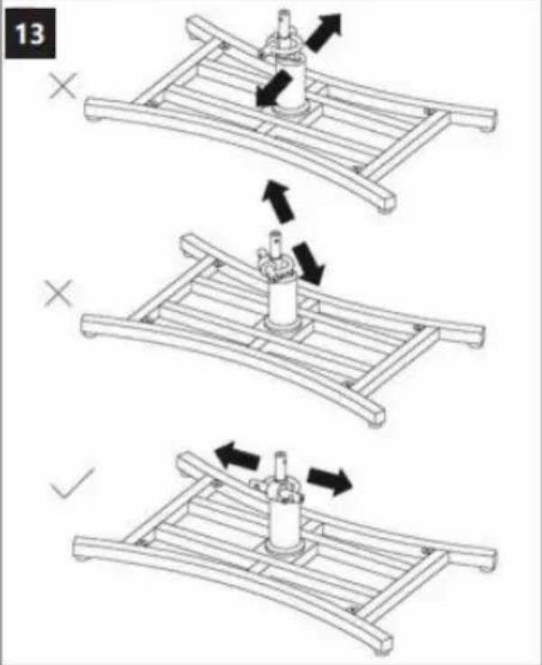
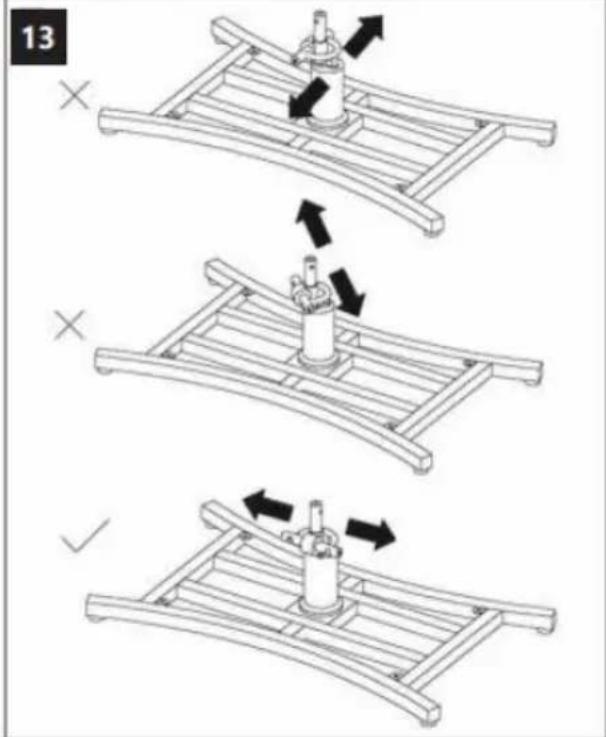
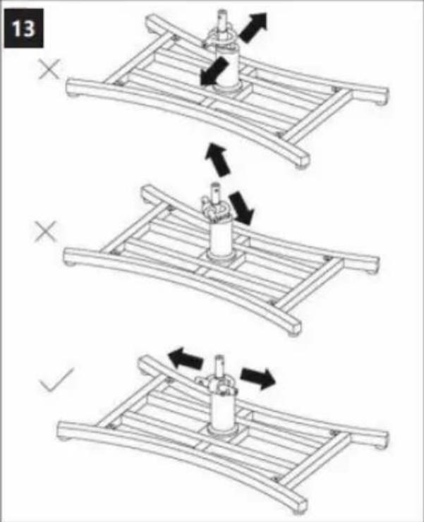
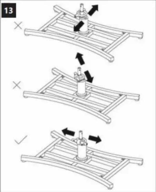
13 X X ✓
natural_image
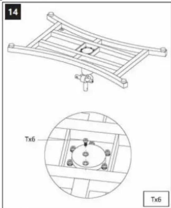
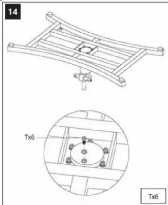
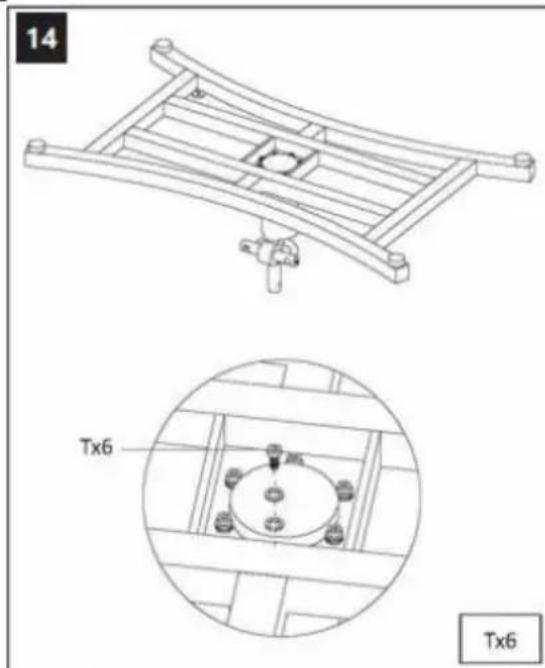
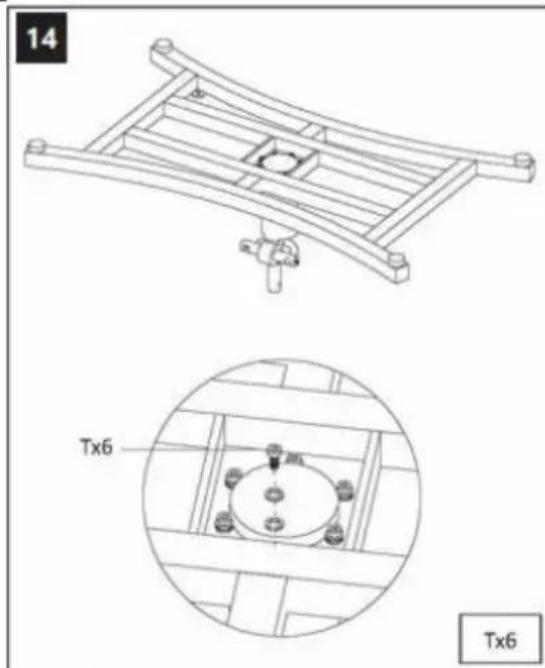
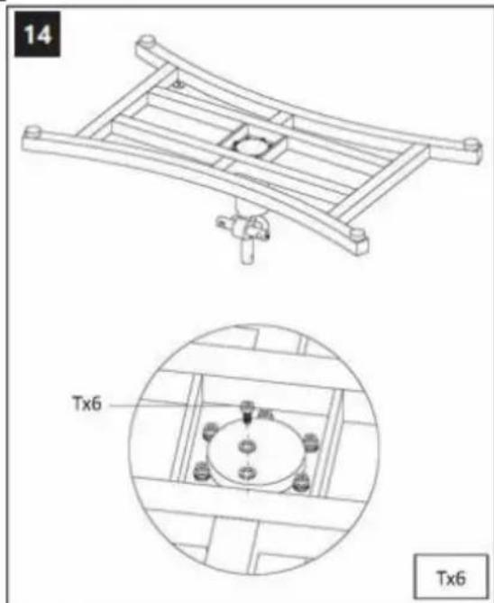
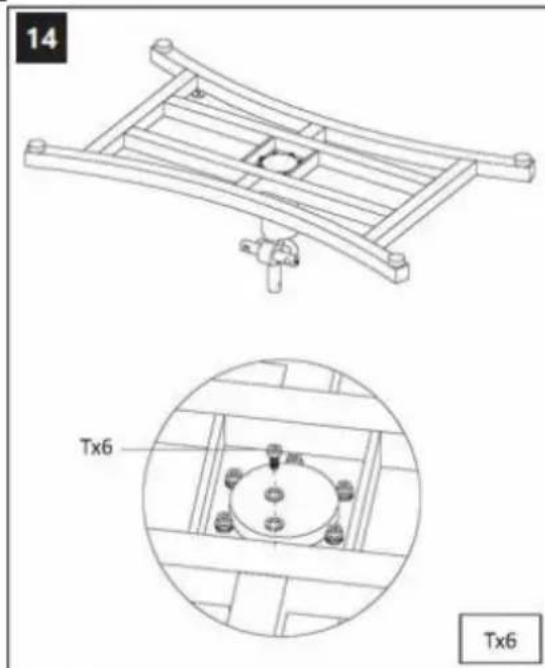
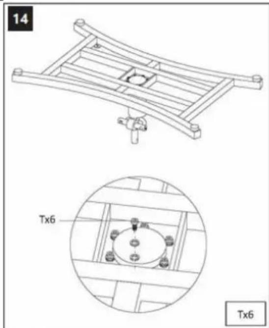
Technical line drawing of a mechanical frame assembly with a detailed close-up view showing internal components (no text or symbols)
text_image
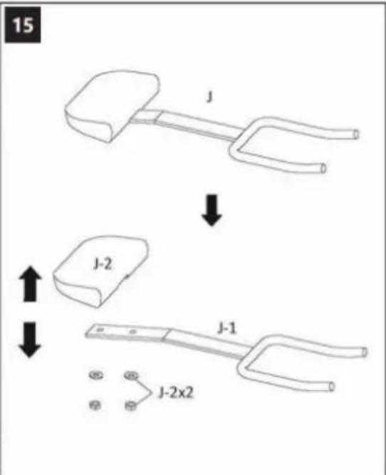
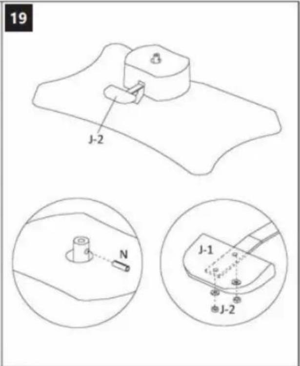
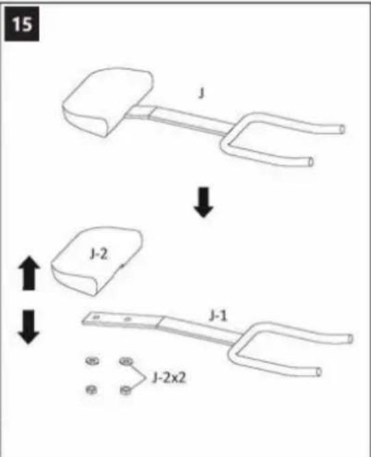
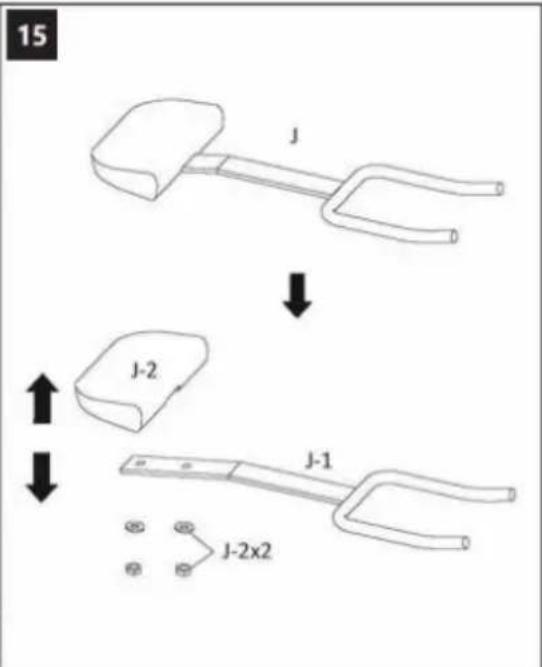
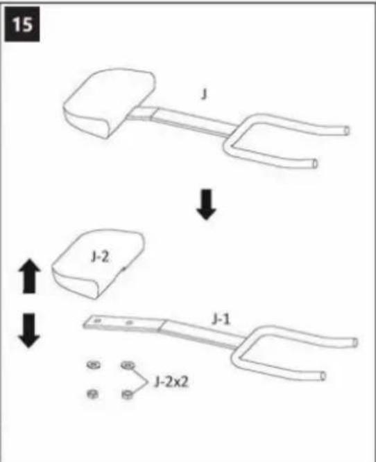
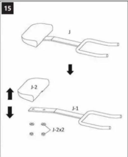
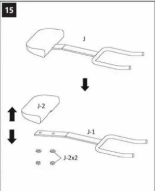
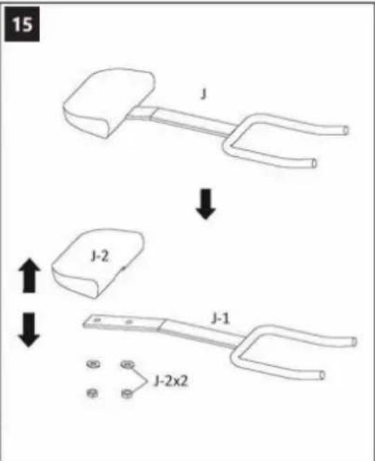
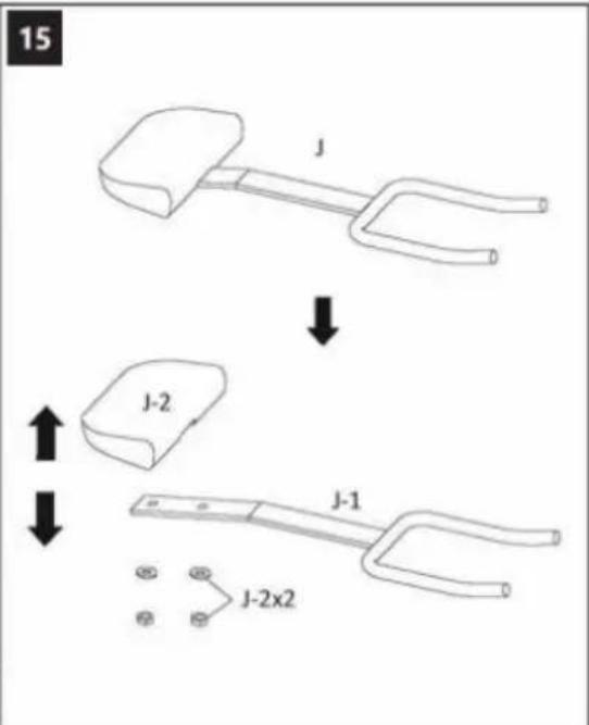
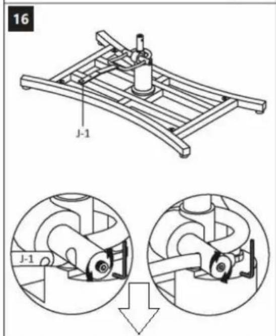
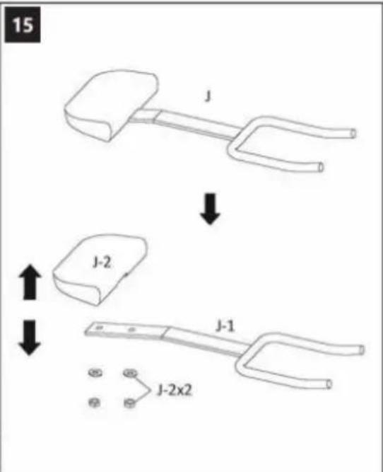
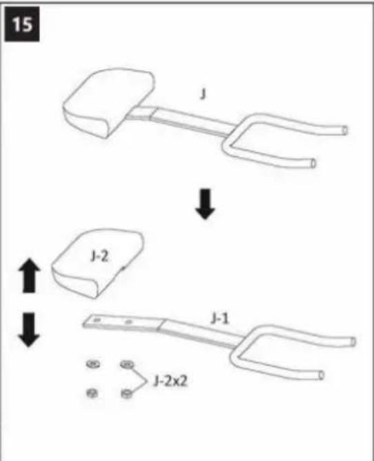
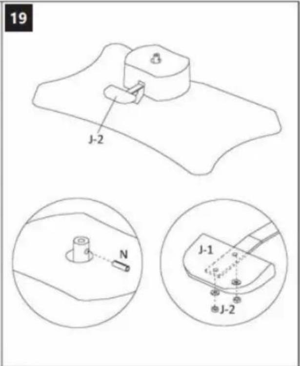
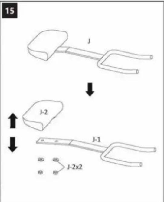
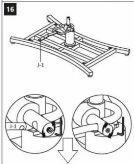
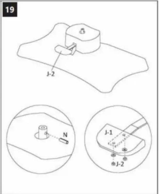
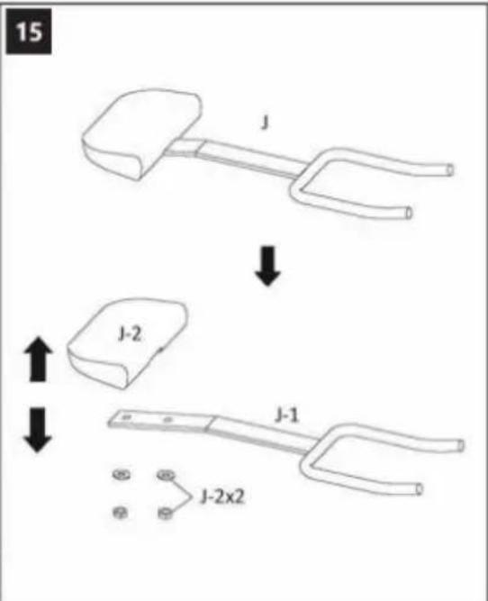
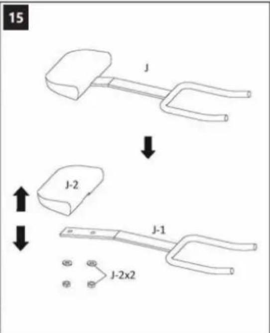
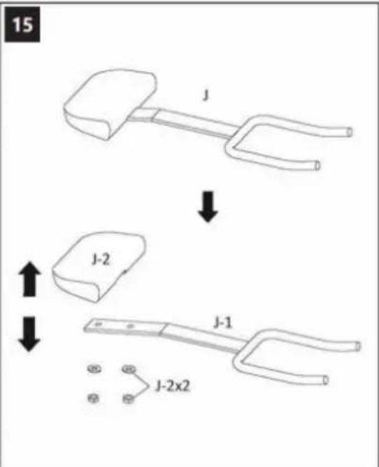
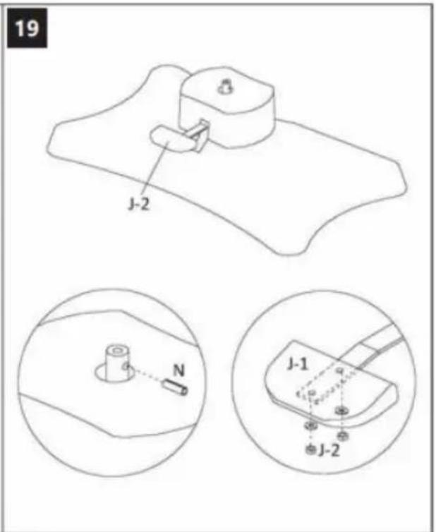
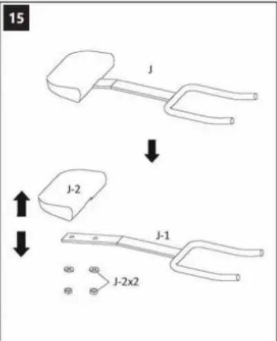
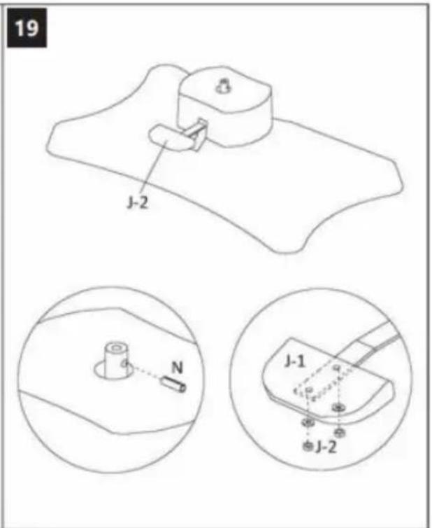
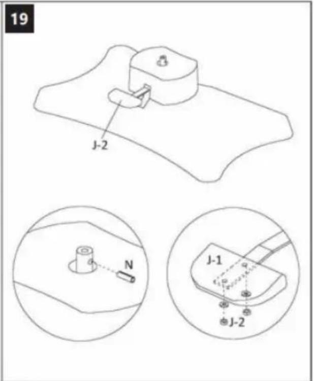
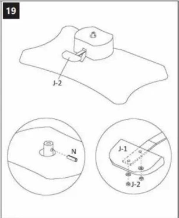
15 J J-2 J-1 J-2x2
text_image
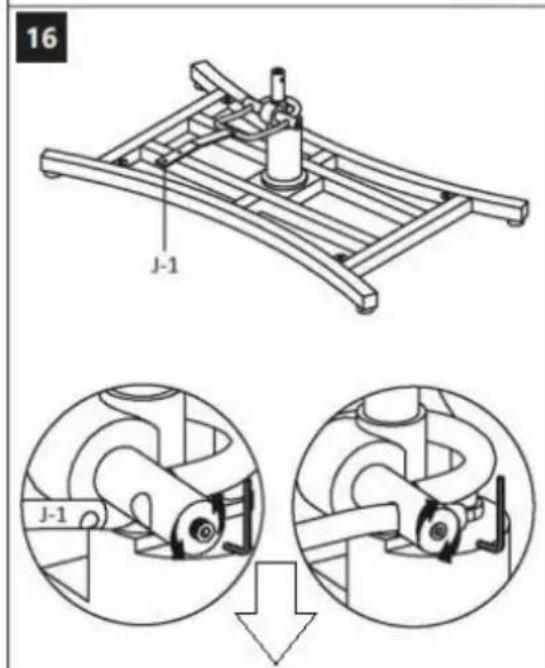
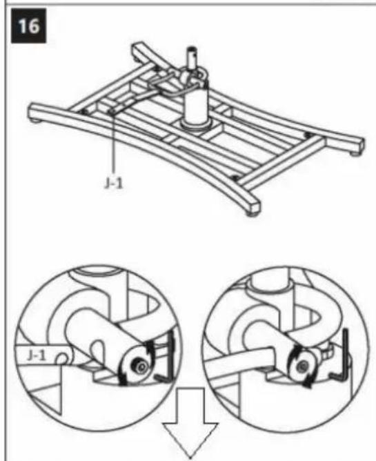
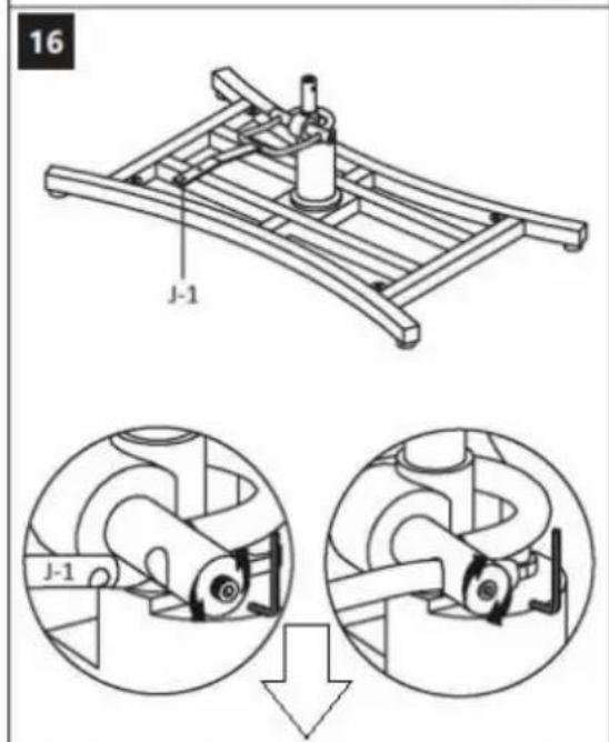
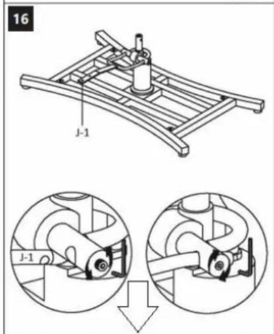
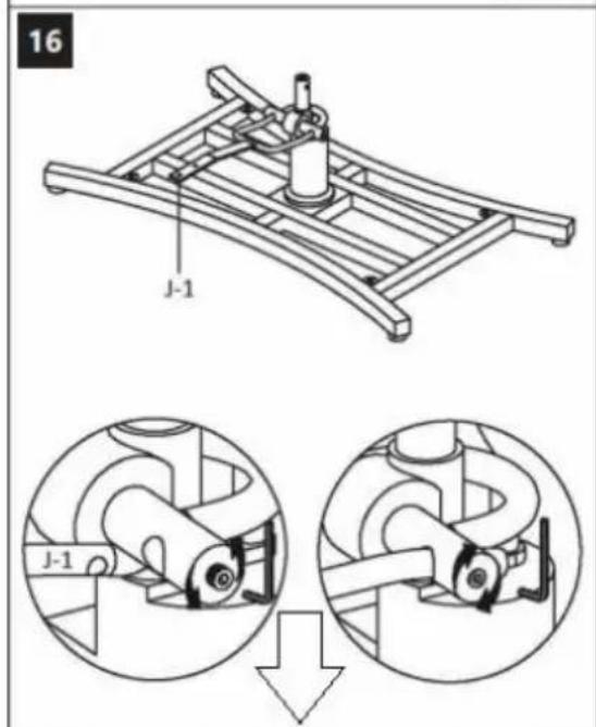
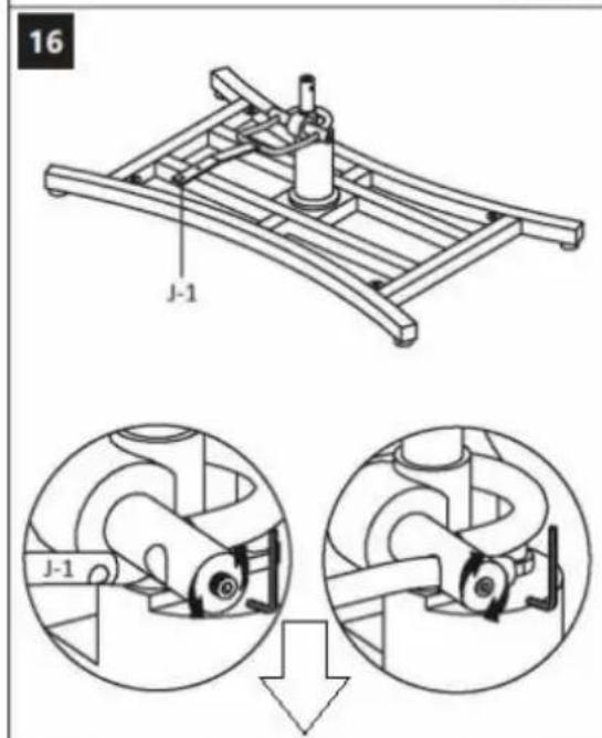
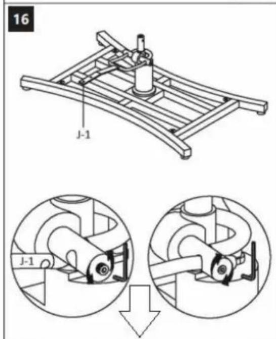
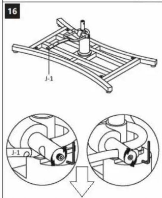
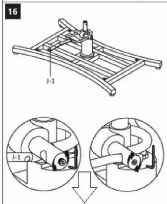
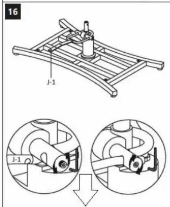
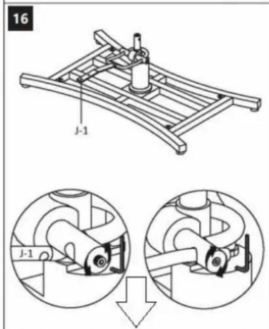
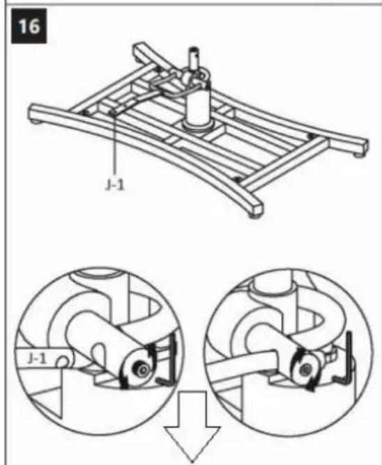
16 J-1 J-1
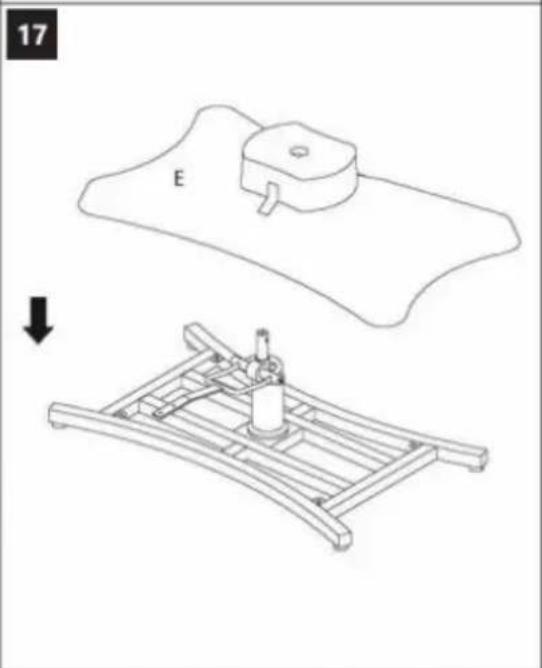
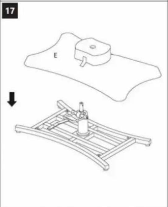
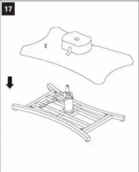
natural_image
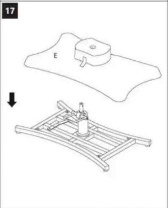
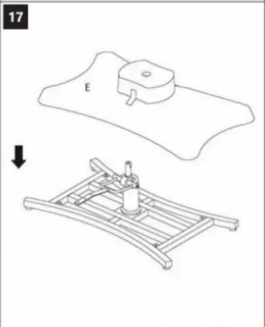
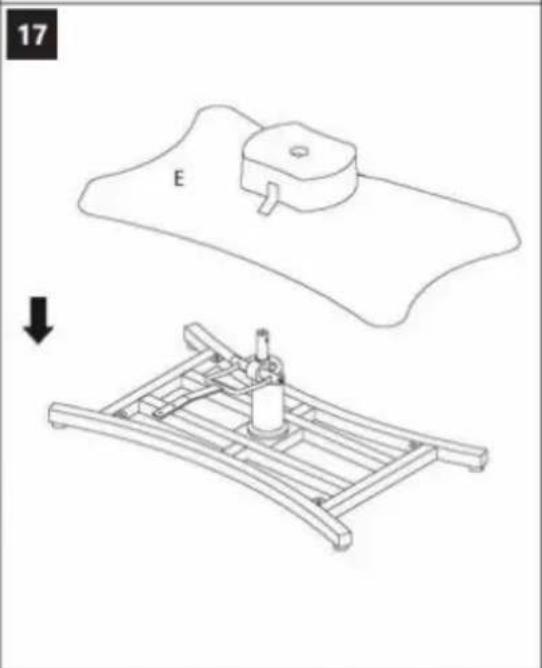
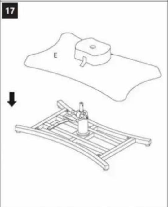
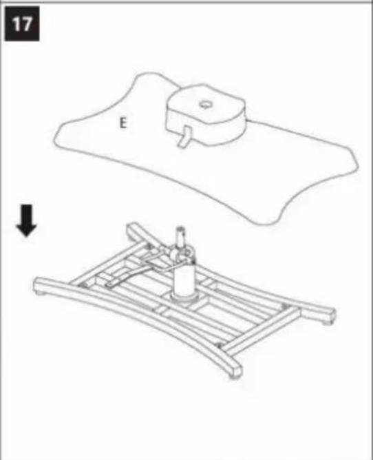
Technical line drawing showing a mechanical assembly with a base plate and a supporting frame, no text or symbols present.
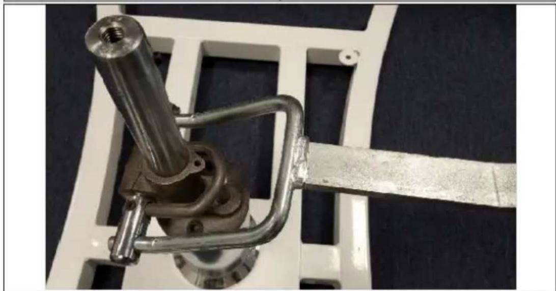
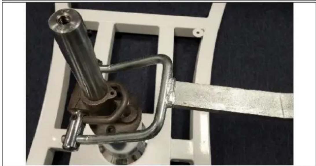
natural_image
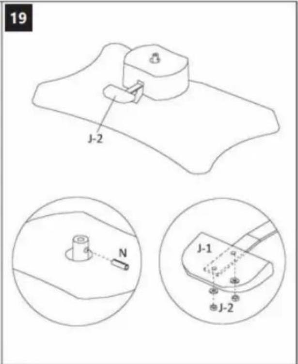
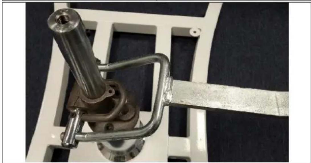
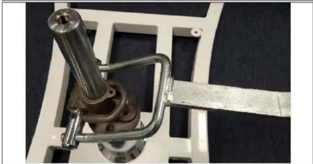
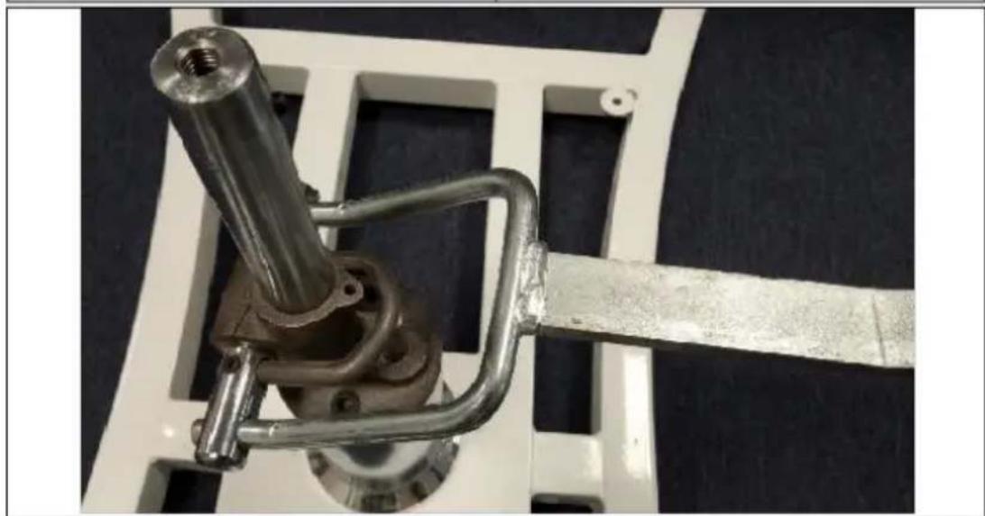
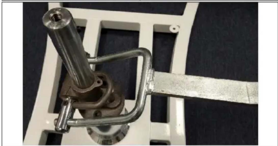
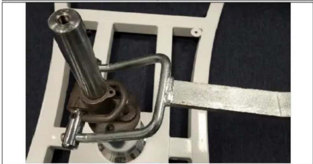
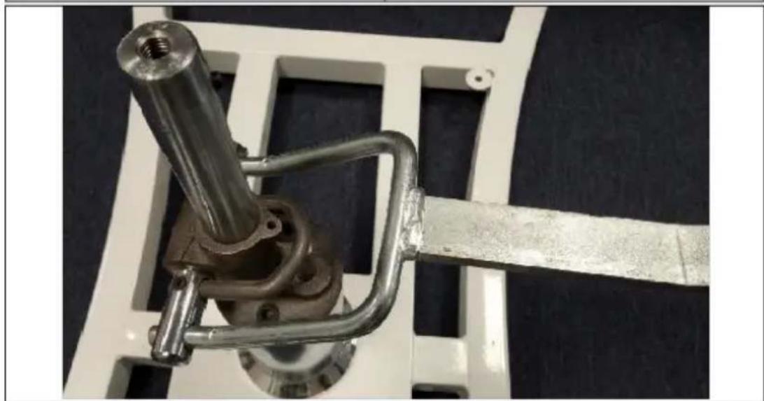
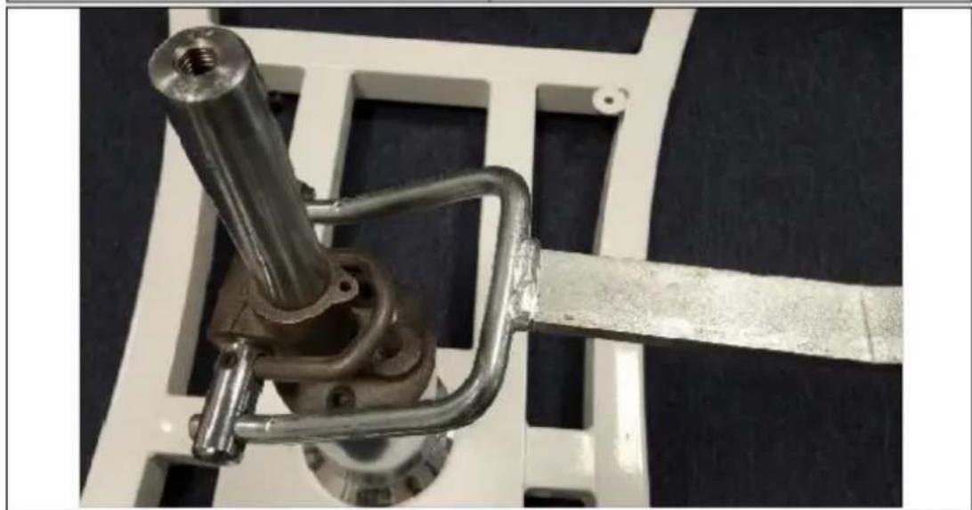
Close-up of a mechanical clamp or bracket assembly with a metallic rod and metal frame, mounted on a white frame (no visible text or symbols)text_image
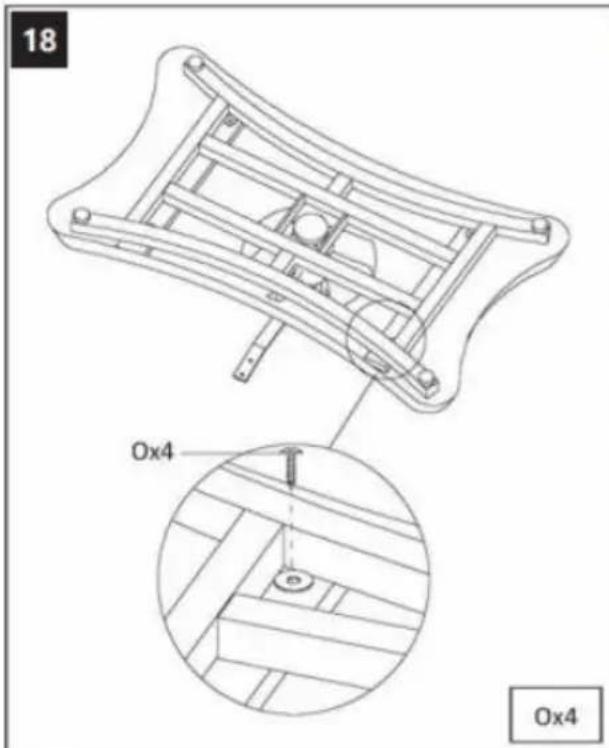
18 Ox4 Ox4
This User Manual has been translated using machine translation. We have made every effort to ensure the translation is accurate, but please note that automated translations are not perfect and are not meant to replace human translators. The official version of the User Manual is in English. Any differences between the translated version and the original English are not legally binding. If you have any questions about the accuracy of the translation, please refer to the English version, which is the official reference. More language versions are available upon request via
info@expondo.com.
Technical data
| Parameter description | Parameter value |
| Product name | Beauty bed |
| Model | PHYSA ARDEA WHITE |
| Dimensions [Width x Depth x Height; mm] | 790 x 1790 x 1170 |
| Weight [kg] | 40.1 |
| Max capacity [kg] | 200 |
1. General description
The user manual is designed to assist in the safe and trouble-free use of the device. The product is designed and manufactured in accordance with strict technical guidelines, using state-of-the-art technologies and components. Additionally, it is produced in compliance with the most stringent quality standards.
DO NOT USE THE DEVICE UNLESS YOU HAVE THOROUGHLY READ AND UNDERSTOOD THIS USER MANUAL.
To increase the product life of the device and to ensure trouble-free operation, use it in accordance with this user manual and regularly perform maintenance tasks. The technical data and specifications in this user manual are up to date. The manufacturer reserves the right to make changes associated with quality improvement. The device is designed to reduce noise emission risks to a minimum, taking into account technological progress and noise reduction opportunities.
Legend

![]() | Read instructions before use. |
![]() | WARNING! or CAUTION! or REMEMBER! Applicable to the given situation.(general warning sign) |
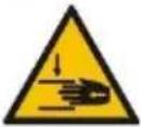
![]() | ATTENTION! Hand crush hazard! |
![]() | Only use indoors. |

PLEASE NOTE! Drawings in this manual are for illustration purposes only and in some details may differ from the actual product.
2. Usage safety

ATTENTION! Read all safety warnings and all instructions. Failure to follow the ings and instructions may result in serious injury or even death.
The terms "device" or "product" are used in the warnings and instructions to refer to the:
Beauty bed.
2.1. Safety in the workplace
a) Make sure the workplace is clean and well lit. A messy or poorly lit workplace may lead to accidents. Try to think ahead, observe what is going on and use common sense when working with the device.
b) If you are unsure about whether the product is operating correctly or if you find damage, please contact the manufacturer's service centre.
c) Only the manufacturer's service centre may make repairs to the product. Do not attempt to make repairs yourself!
EN
d) Regularly inspect the condition of the safety labels. If the labels are illegible, they must be replaced.
e) Please keep this manual available for future reference. If this device is passed on to a third party, the manual must be passed on with it.
f) Keep packaging elements and small assembly parts in a place not available to children.
g) If this device is used together with another equipment, the remaining instructions for use shall also be followed.
2.2. Personal safety
a) Do not use the device when tired, ill or under the influence of alcohol, narcotics or medication which can significantly impair the ability to operate the device.
b) The device is not designed to be handled by persons (including children) with limited mental and sensory functions or persons lacking relevant experience and/or knowledge unless they are supervised by a person responsible for their safety or they have received instruction on how to operate the device.
c) When working with the device, use common sense and stay alert. Temporary loss of concentration while using the device may lead to serious injuries.
d) Do not overestimate your abilities. When using the device, keep your balance and remain stable at all times. This will ensure better control over the device in unexpected situations.
e) Remove all adjusting tools or spanners before turning the device on. A tool or spanner left in the revolving part of the device may cause injury.
f) The device is not a toy. Children must be supervised to ensure that they do not play with the device.
g) Do not put your hands or other items inside the device while it is in use!
h) Inadequate tightening of adjustment mechanisms (such as screws or knobs) may result in sudden movement or loss of positional stability, risking injury to the client or practitioner.
2.3. Safe device use
a) Keep the device in perfect technical condition. Before each use check for general damage and especially check for cracked parts or elements and for any other conditions which may impact the safe operation of the device. If damage is discovered, hand over the device for repair before use.
b) Device repair or maintenance should be carried out by qualified persons, only using original spare parts. This will ensure safe use.
c) To ensure the operational integrity of the device, do not remove factory-fitted guards and do not loosen any screws.
d) When transporting and handling the device between the warehouse and the destination, observe the occupational health and safety principles for manual transport operations which apply in the country where the device will be used. Moving the product without locking the adjustable sections or using improper lifting techniques can result in personal injury or product damage.
e) Clean the device regularly to prevent stubborn grime from accumulating.
f) The specified vibrations emission was measured using standard measurement methods. Vibrations emissions may change if the device is used in different surroundings.
g) The device is not a toy. Cleaning and maintenance may not be carried out by children without supervision by an adult person.
h) It is forbidden to interfere with the structure of the device in order to change its parameters or construction.
i) Keep the device away from sources of fire and heat.
j) Exceeding the maximum permissible user weight can damage the product.
k) Improper assembly or use on uneven surfaces may lead to bed instability, potentially causing tipping or collapsing.

ATTENTION! Despite the safe design of the device and its protective features, and despite the use of additional elements protecting the operator, there is still a slight risk of accident or injury when using the device. Stay alert and use common sense when using the device.
3. Use guidelines
The product is designed for use in professional environments, such as beauty salons, spas, wellness centers, and clinics, to provide ergonomic support and comfort for clients during various treatments.
This product is outside the scope of REGULATION (EU) 2017/745 for medical devices. It has not been designed as a medical device.
The user is liable for any damage resulting from unintended use of the device.
3.1. Preparing for use
APPLIANCE LOCATION
The ambient temperature must not exceed 45^ C and the relative humidity should not exceed 85%. Keep the device away from any hot surfaces. The device should always be used when positioned on an even, stable, clean and dry surface, and be out of the reach of children and persons with limited mental and sensory functions.
ASSEMBLY
- Parts list:
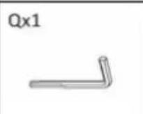
Ax1![]() | Bx1![]() | Cx1![]() | Dx1![]() | Ex1![]() | Fx1![]() |
Gx1![]() | Hx2![]() | Ix1![]() | Jx1![]() | Kx2![]() | Lx1![]() |
Mx1![]() | Nx1[287H] | Ox4![]() | Px1![]() | Qx1![]() |
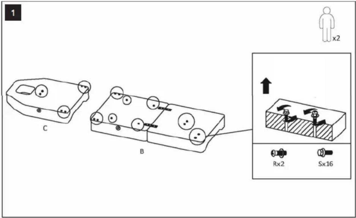
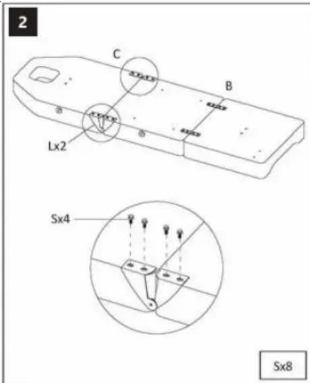
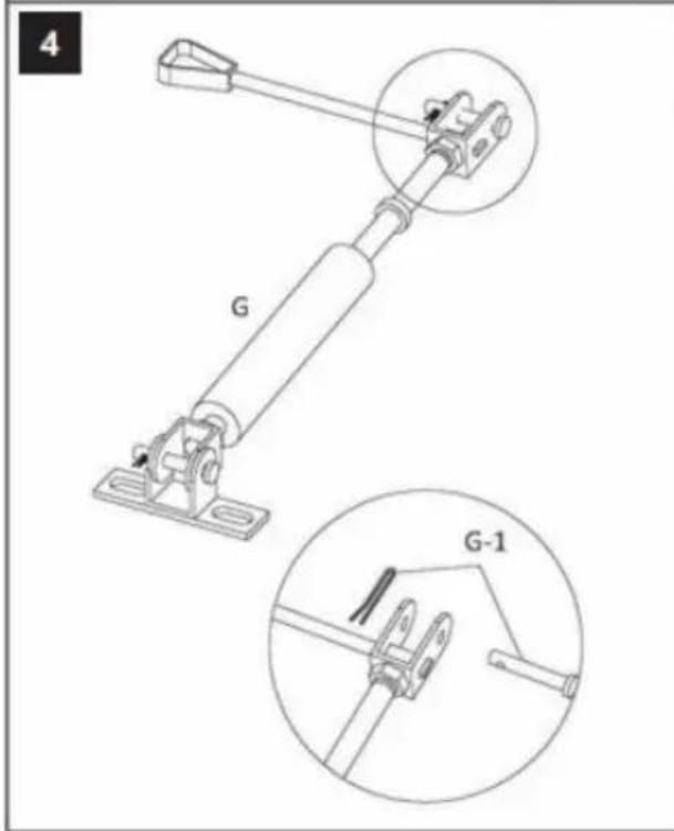
- Assembling the product:
text_image
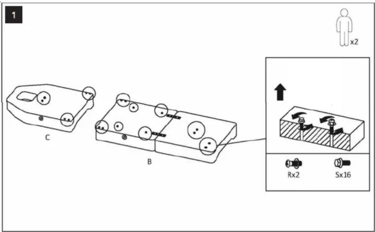
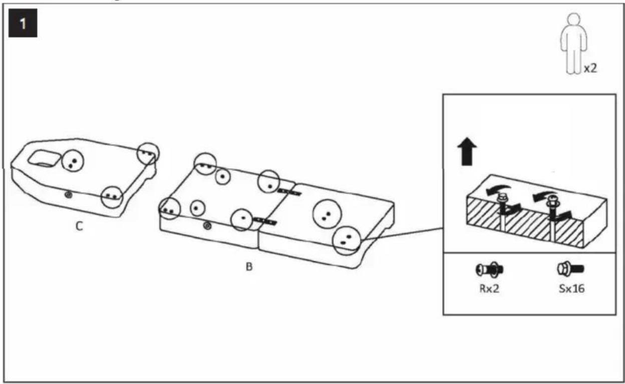
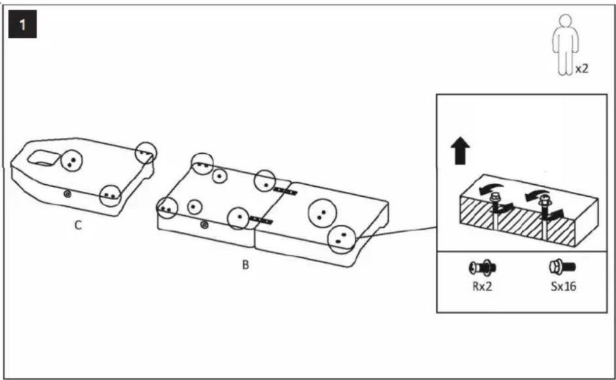
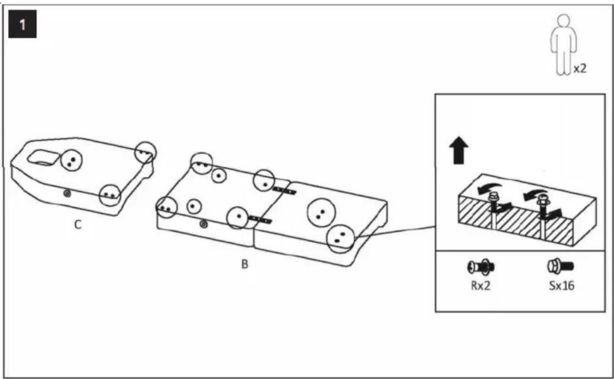
1 C B Rx2 Sx16
text_image
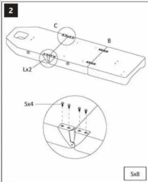
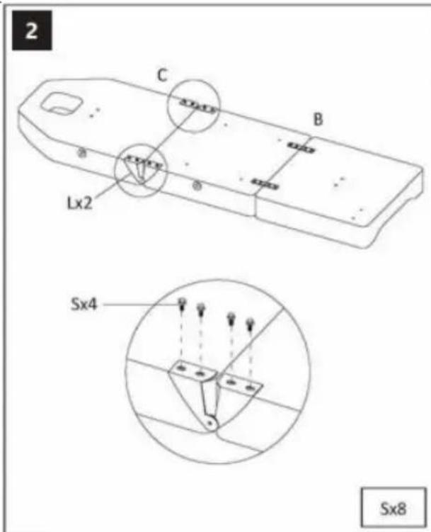
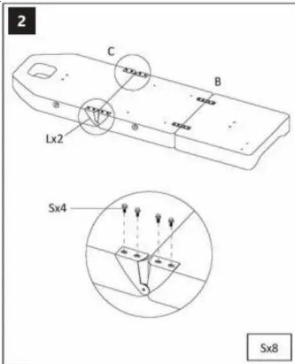
2 C B Lx2 Sx4 Sx8
text_image
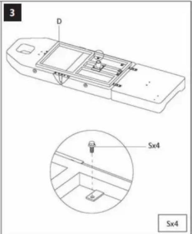
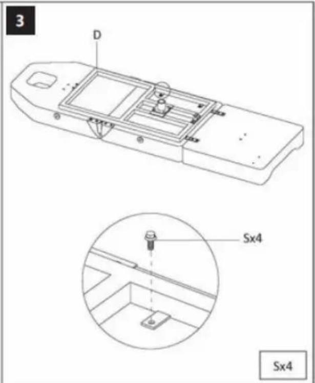
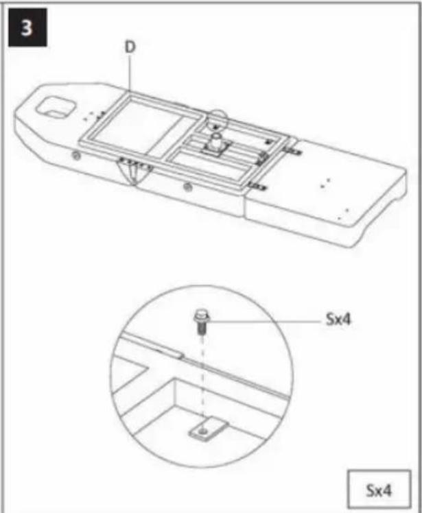
3 D Sx4 Sx4
text_image
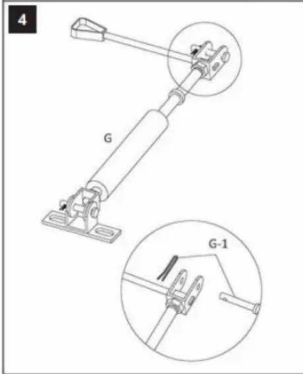
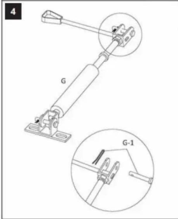
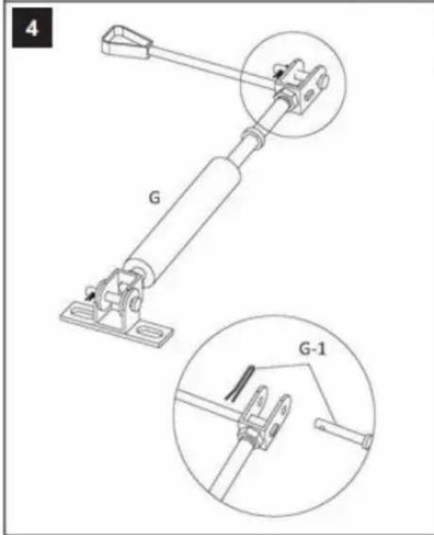
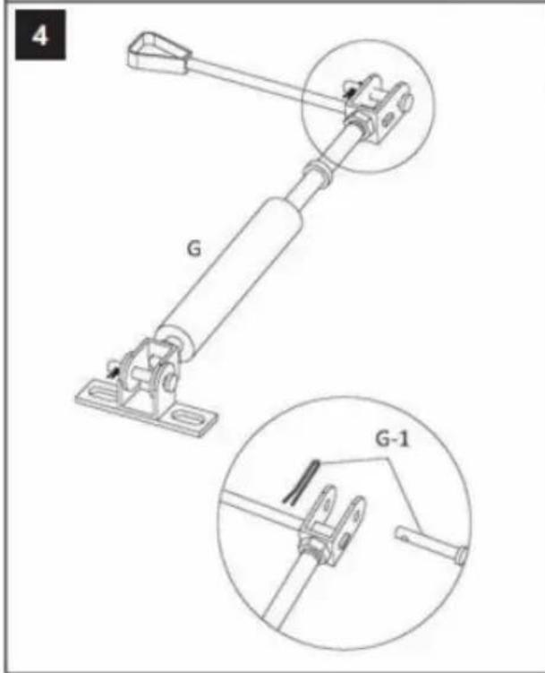
4 G G-1
text_image
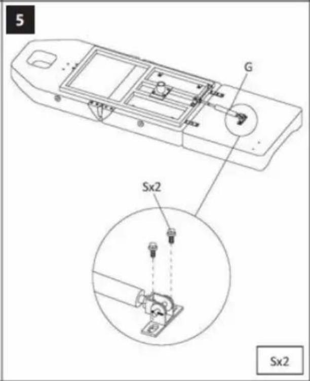
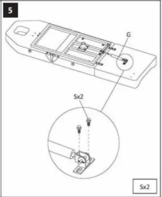
5 G Sx2 Sx2
text_image
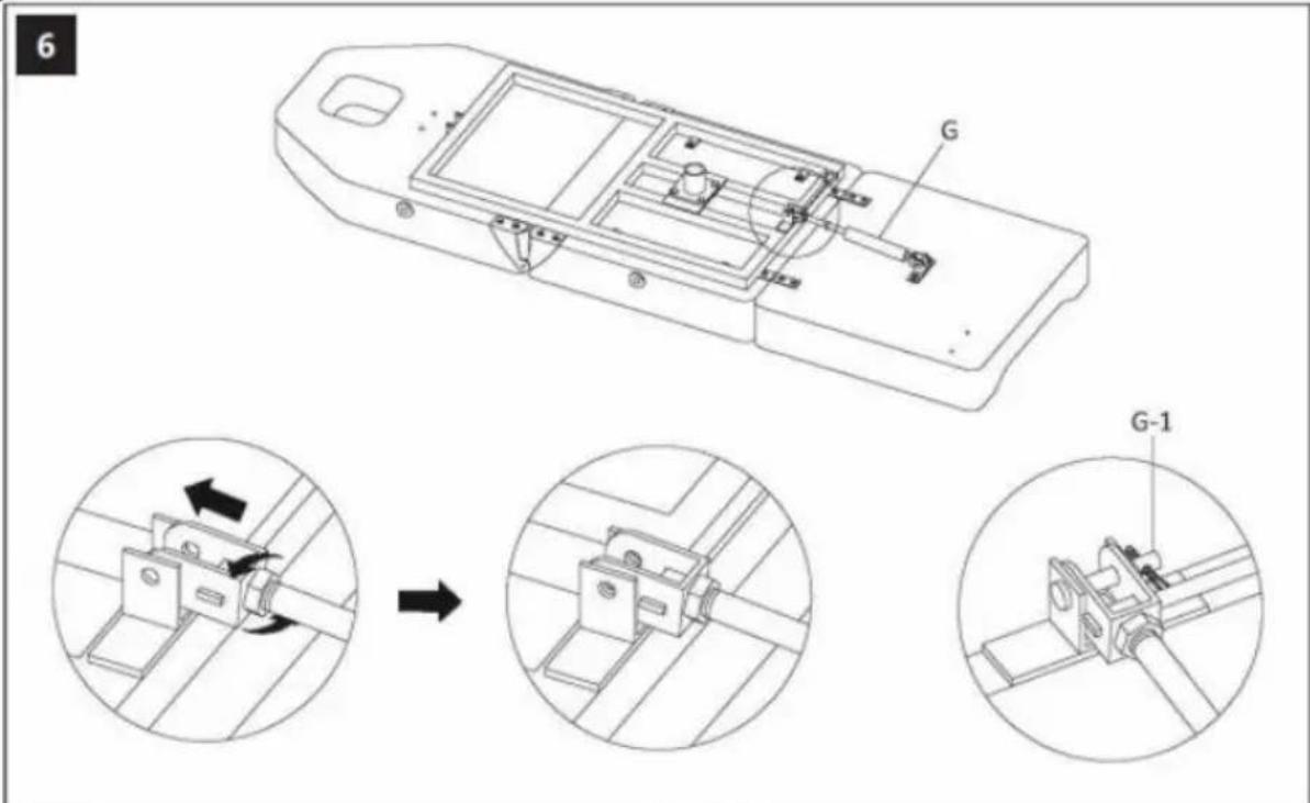
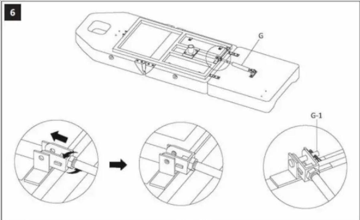
6 G G-1
text_image
7 M M-1 M-2 M-3
text_image
9 M-2 L-1 Sx2 M-2 L-1 L-2 Sx2
text_image
8 L L-1 L-2
text_image
6 G G-1 7 M M-1 M-2 M-3 9 M-2 L-1 Sx2 8 L L-1 L-2 L-1 L-2 Sx2
text_image
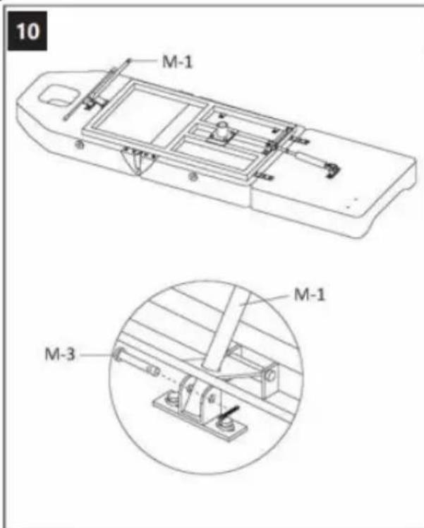
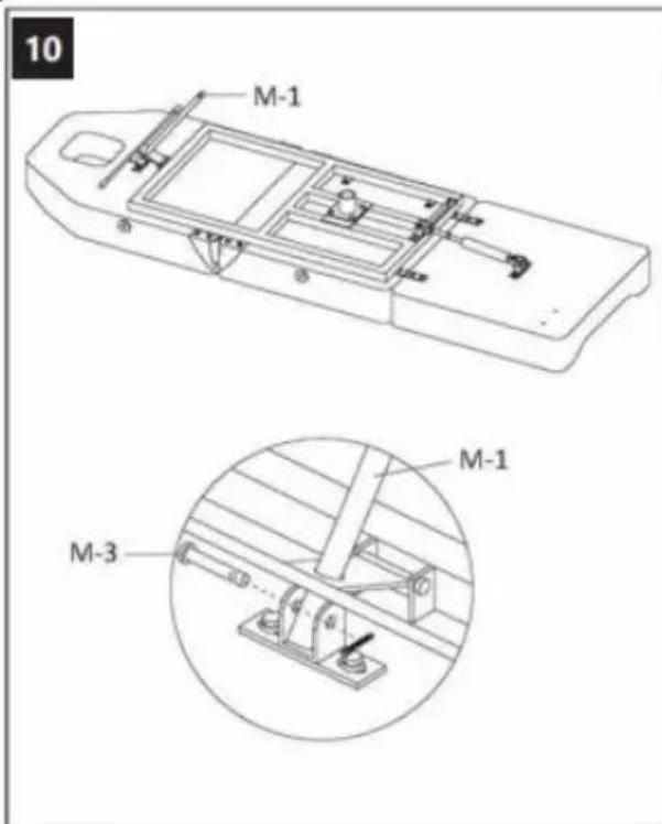
10 M-1 M-1 M-3
text_image
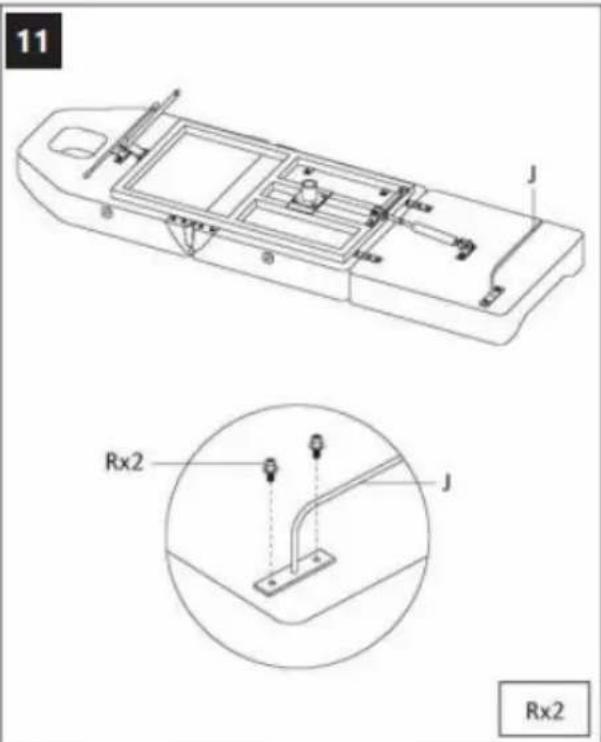
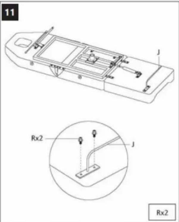
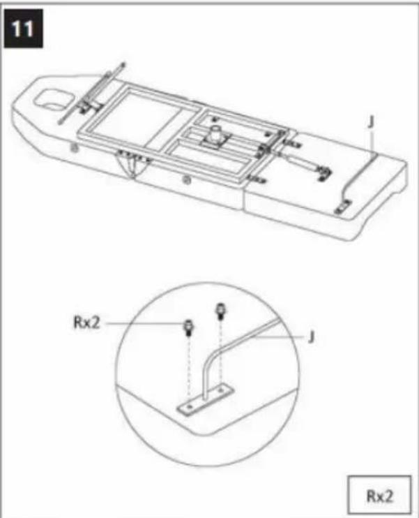
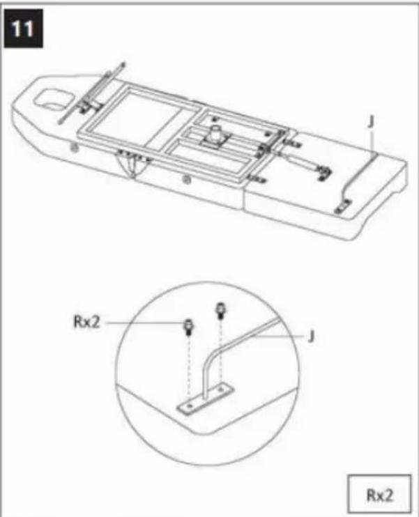
11 J Rx2 J Rx2
text_image
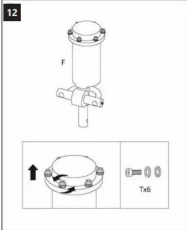
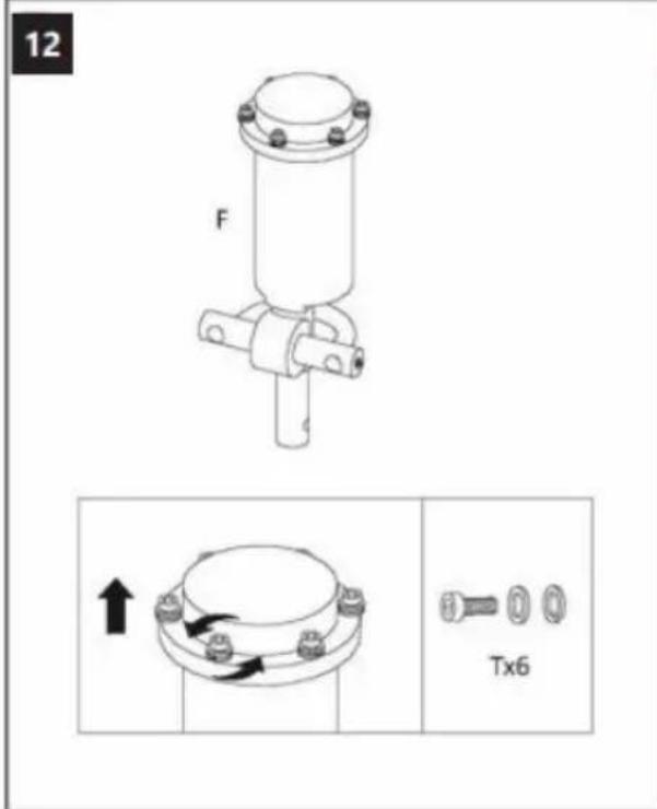
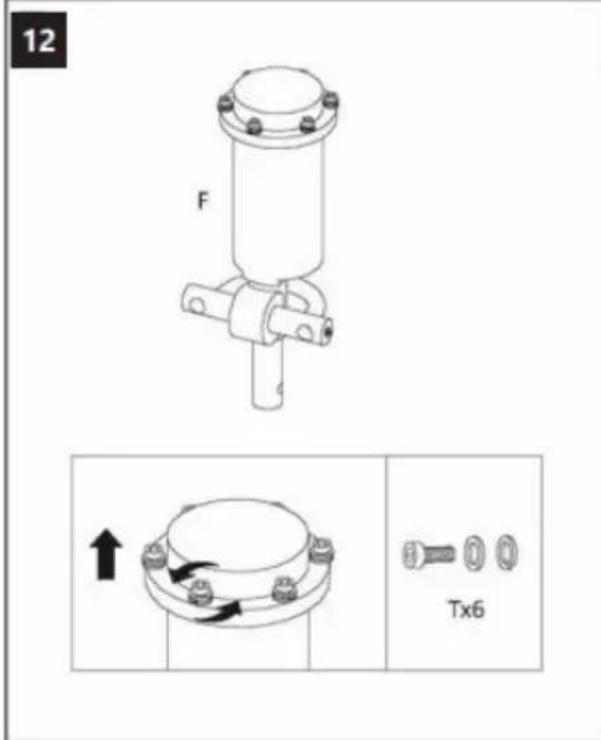
12 F Tx6
text_image
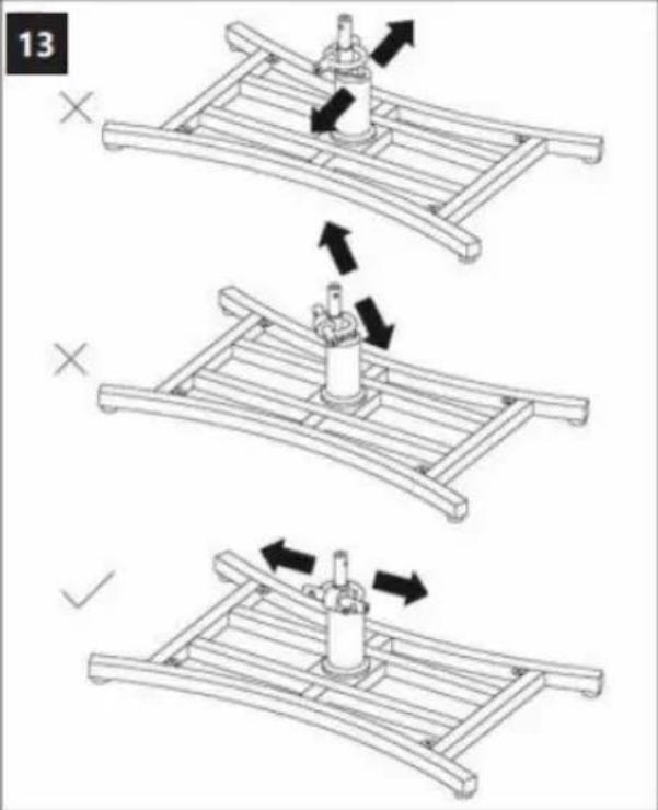
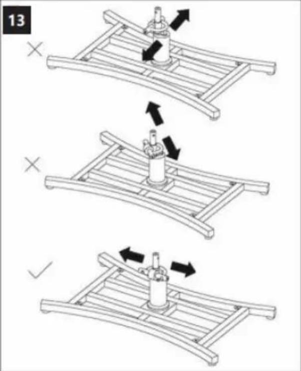
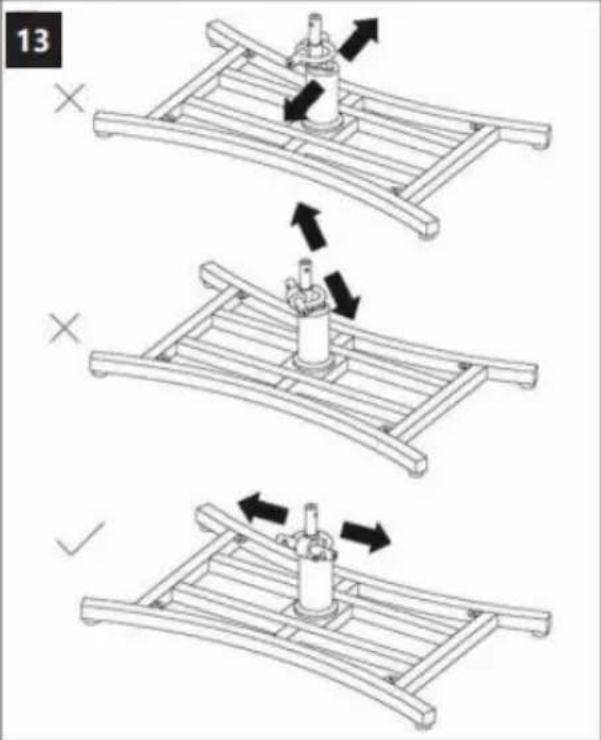
13 X X ✓
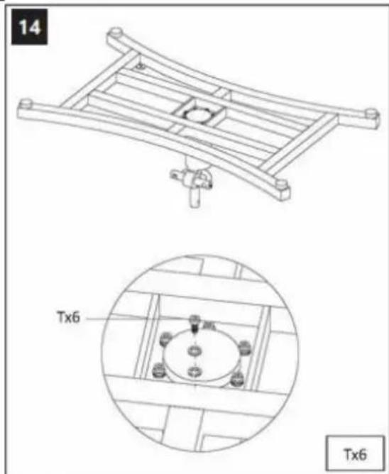
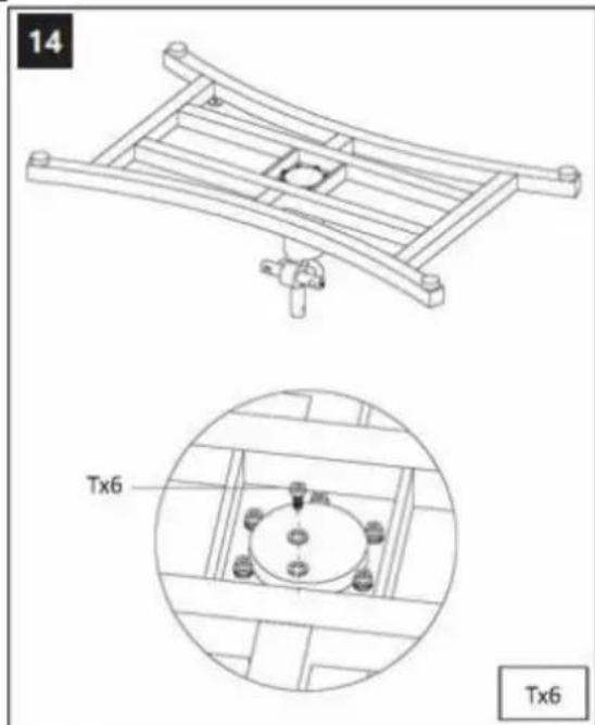
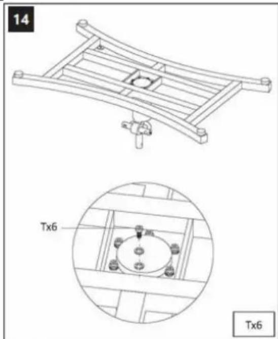
natural_image
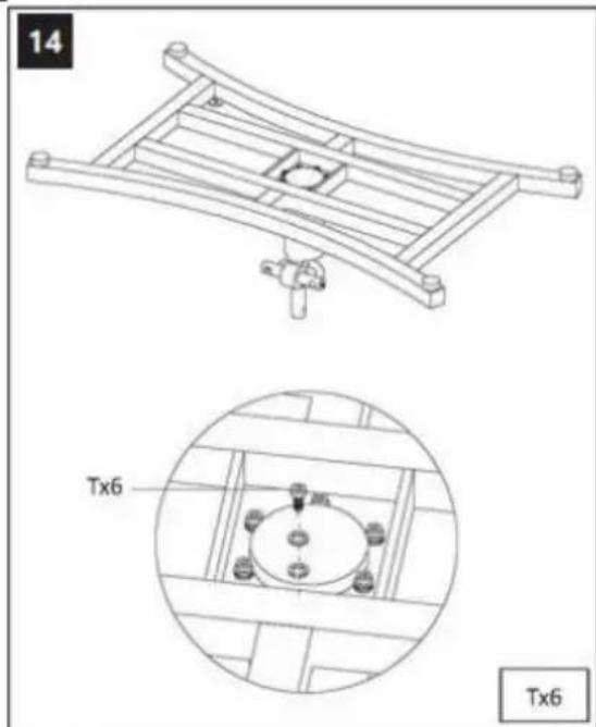
Technical line drawing of a mechanical frame assembly with a detailed close-up view showing internal components (no text or symbols)
text_image
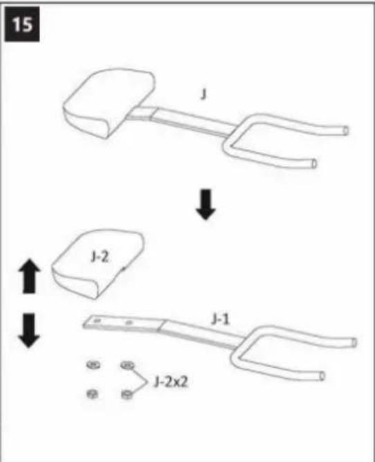
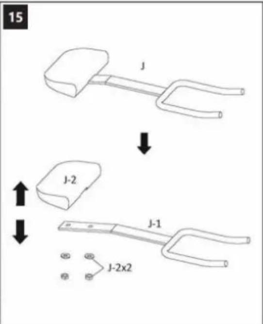
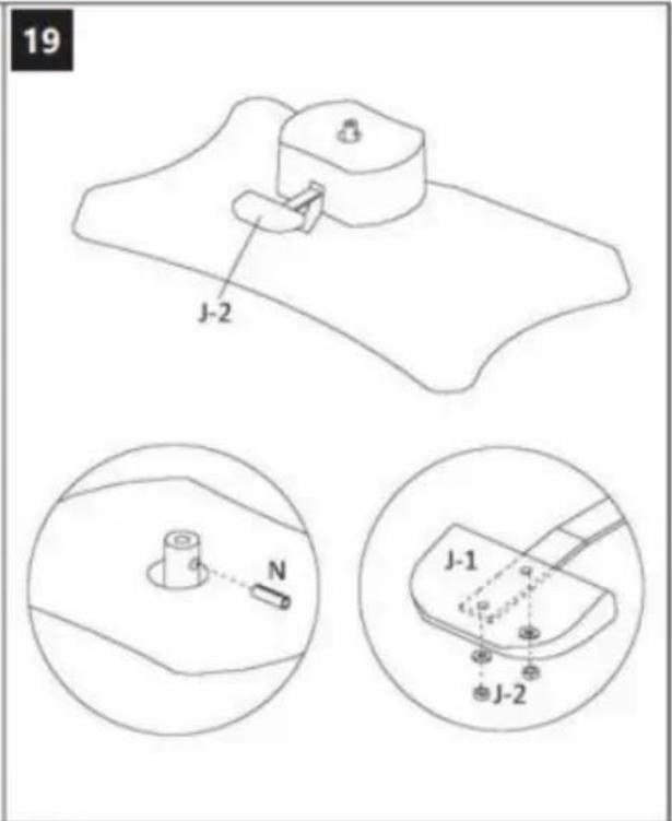
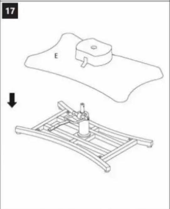
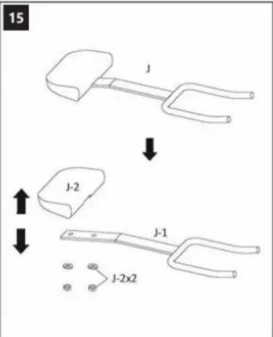
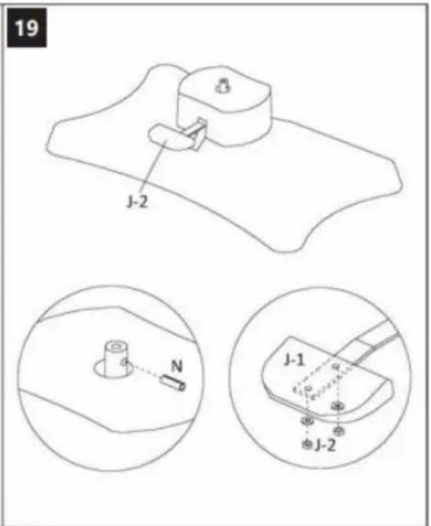
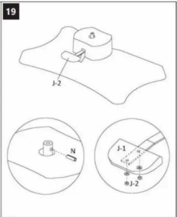
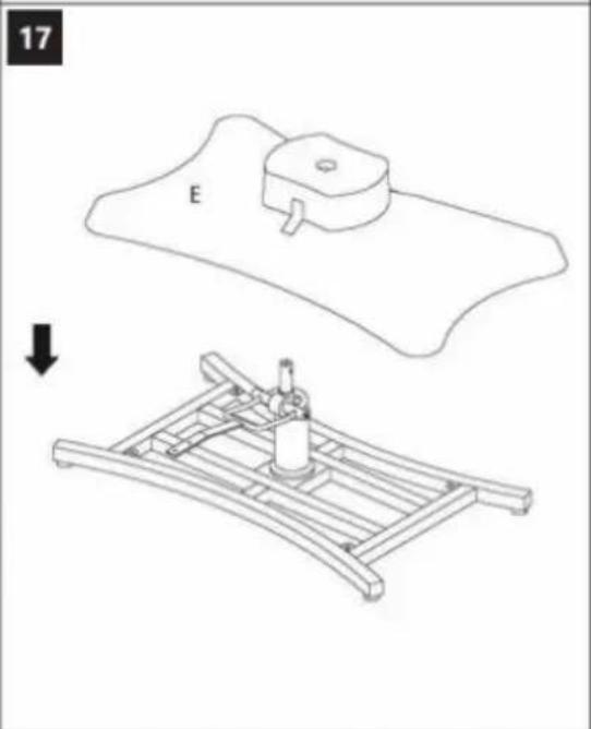
15 J J-2 J-1 J-2x2
text_image
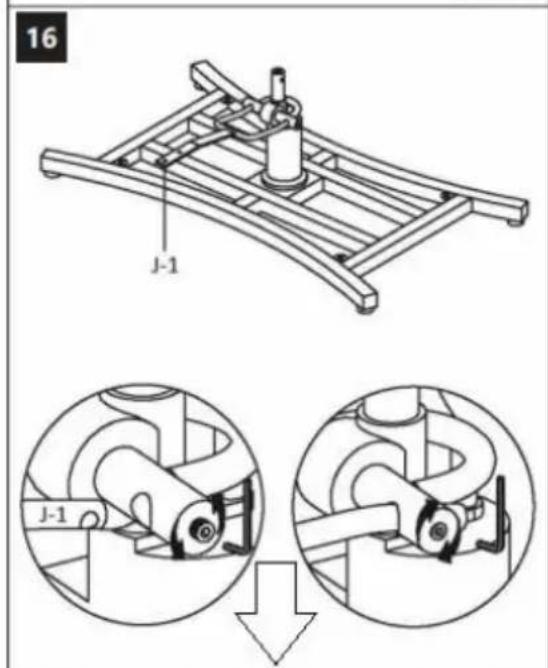
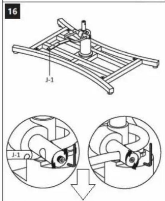
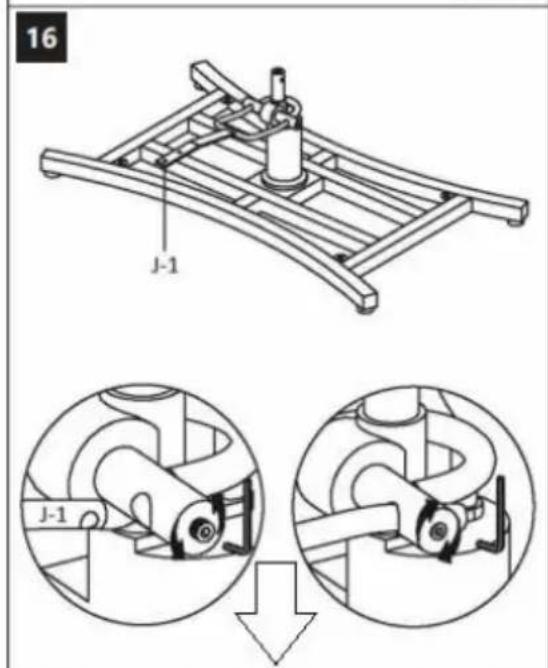
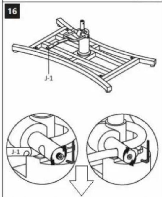
16 J-1 J-1
natural_image
Technical line drawing showing a mechanical assembly with a base plate and a supporting frame, no text or symbols present.
natural_image
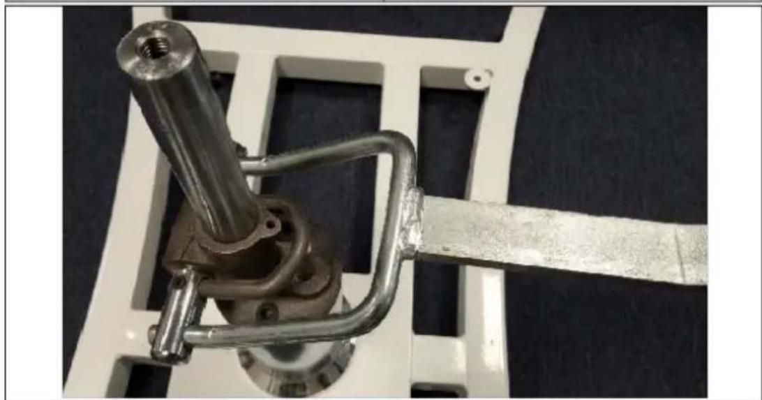
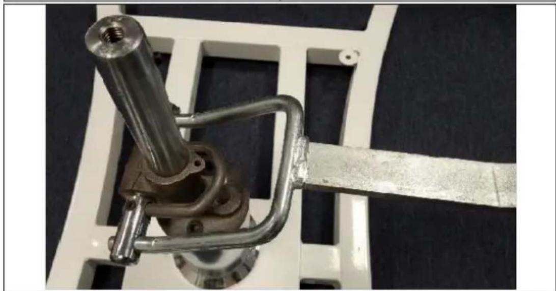
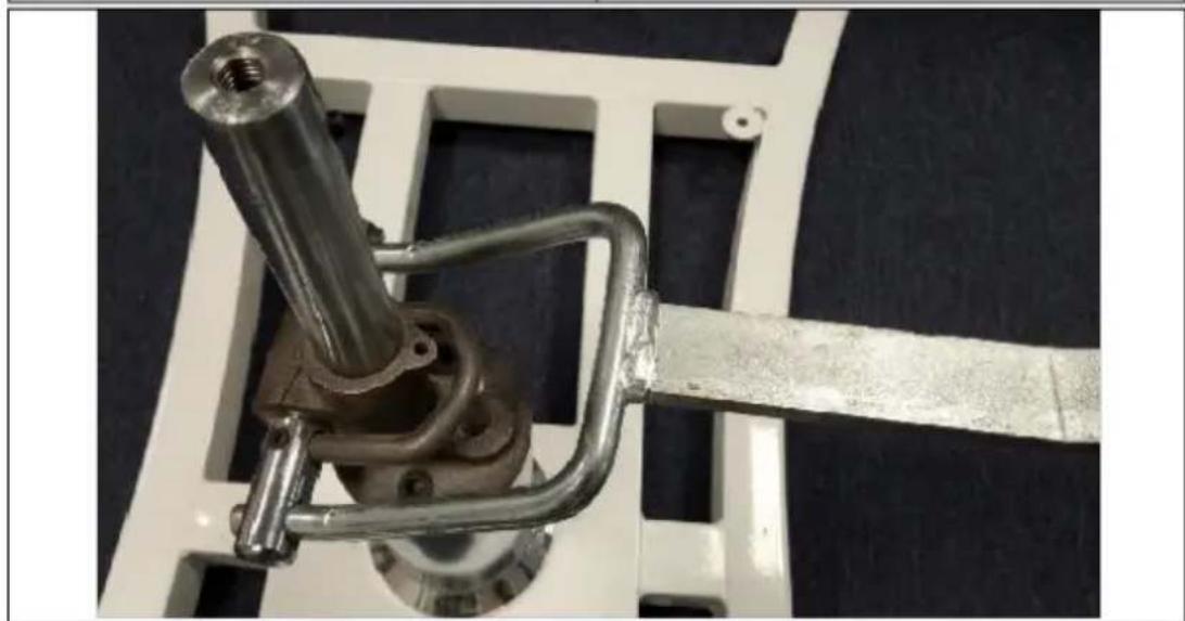
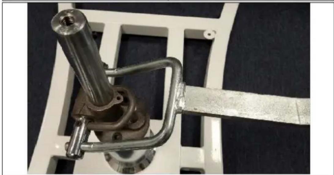
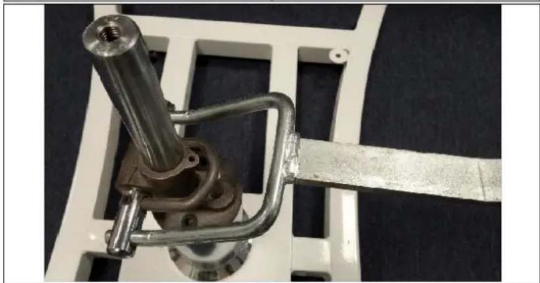
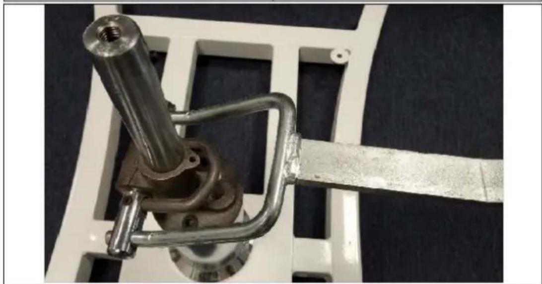
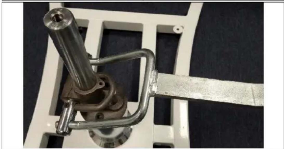
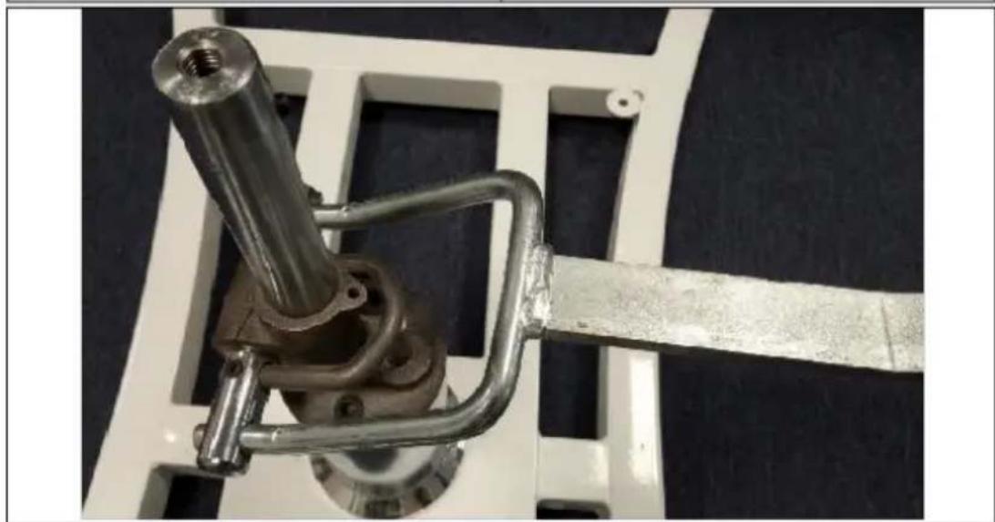
Close-up of a mechanical clamp or bracket assembly with a metallic rod and metal frame, mounted on a white frame (no visible text or symbols)NOTE: pay attention to the correct direction of the pumping assembly (16) as shown on the photo above.
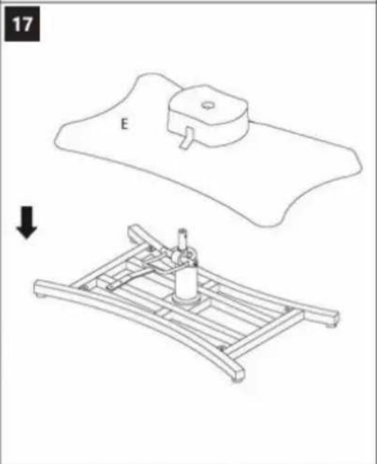
text_image
18 Ox4 Ox4
3.2. Cleaning and maintenance
a) Use only non-corrosive cleaners to clean the surface.
b) Store the unit in a dry, cool place, free from moisture and direct exposure to sunlight.
c) Do not spray the device with a water jet or submerge it in water.
d) The device must be regularly inspected to check its technical efficiency and spot any damage.
e) Use a soft, damp cloth for cleaning.
f) Do not use sharp and/or metal objects for cleaning (e.g. a wire brush or a metal spatula) because they may damage the surface material of the appliance.
g) Do not clean the device with an acidic substance, agents of medical purposes, thinners, fuel, oils or other chemical substances because it may damage the device.
h) Clean and disinfect the bed between uses, following manufacturer recommendations and using suitable cleaning agents.

Ax1![]() | Bx1![]() | Cx1![]() | Dx1![]() | Ex1![]() | Fx1![]() |
Gx1![]() | Hx2![]() | Ix1![]() | Jx1![]() | Kx2![]() | Lx1![]() |
Mx1![]() | Nx1![]() | Ox4![]() | Px1![]() | Qx1![]() |
- Montaż produktu:

text_image
1 C B Rx2 Sx16PL

text_image
6 G G-1
text_image
7 M M-1 M-2 M-3
text_image
9 M-2 L-1 Sx2 M-2 L-1 L-2 Sx2
text_image
8 L L-1 L-2
text_image
10 M-1 M-1 M-3
text_image
11 J Rx2 J Rx2
text_image
12 F Tx6
text_image
13 X X ✓
text_image
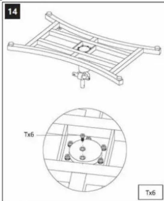
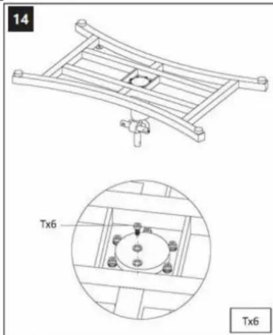
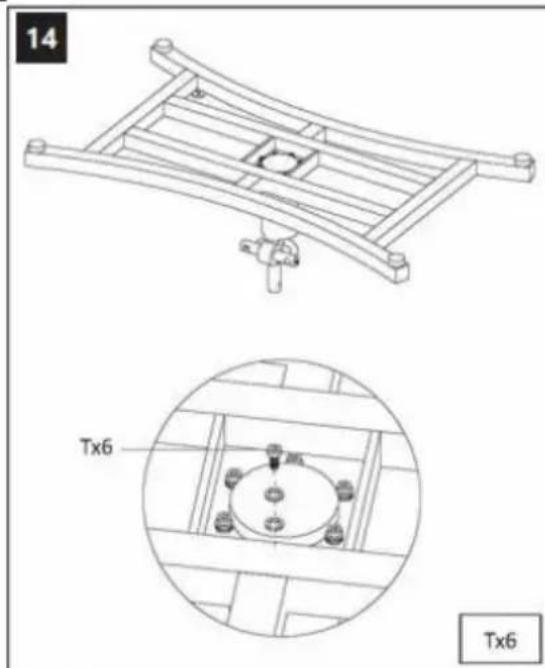
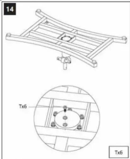
14 Tx6 Tx6
text_image
15 J J-2 J-1 J-2x2
text_image
16 J-1 J-1
natural_image
Technical line drawing showing a mechanical assembly with a base plate and a supporting frame, no text or symbols present.
natural_image
Close-up of a mechanical clamp or bracket assembly with metallic components and a metal rod, mounted on a white frame (no visible text or symbols)PL
Ax1![]() | Bx1![]() | Cx1![]() | Dx1![]() | Ex1![]() | Fx1![]() |
Gx1![]() | Hx2![]() | Ix1![]() | Jx1![]() | Kx2![]() | Lx1![]() |
Mx1![]() | Nx1![]() | Ox4![]() | Px1![]() | Qx1![]() |
text_image
3 D Sx4 Sx4
text_image
4 G G-1
text_image
5 G Sx2 Sx2
text_image
6 G G-1
text_image
7 M M-1 M-2 M-3
text_image
9 M-2 L-1 Sx2 M-2 L-1 L-2 Sx2
text_image
8 L L-1 L-2
text_image
6 G G-1 7 M M-1 M-2 M-3 9 M-2 L-1 Sx2 8 L L-1 L-2 L-1 L-2 Sx2
text_image
10 M-1 M-1 M-3
text_image
11 J Rx2 J Rx2
text_image
12 F Tx6
text_image
13 X X ✓
natural_image
Technical line drawing of a mechanical structure with a detailed inset showing a circular component labeled Tx6 (no text or symbols beyond labels)
text_image
15 J J-2 J-1 J-2x2
text_image
16 J-1 J-1
natural_image
Technical line drawing showing a mechanical assembly with a base plate and a supporting frame, no text or symbols present.
natural_image
Close-up of a mechanical clamp or bracket assembly with metallic components and a metal rod, mounted on a white frame (no visible text or symbols)text_image
18 Ox4 Ox4
Ax1![]() | Bx1![]() | Cx1![]() | Dx1![]() | Ex1![]() | Fx1![]() |
Gx1![]() | Hx2![]() | Ix1![]() | Jx1![]() | Kx2![]() | Lx1![]() |
Mx1![]() | Nx1![]() | Ox4![]() | Px1![]() | Qx1![]() |
text_image
11 J Rx2 J Rx2
text_image
12 F ↑ Tx6
text_image
13 X X ✓FR
Ax1![]() | Bx1![]() | Cx1![]() | Dx1![]() | Ex1![]() | Fx1![]() |
Gx1![]() | Hx2![]() | Ix1![]() | Jx1![]() | Kx2![]() | Lx1![]() |
Mx1![]() | Nx1![]() | Ox4![]() | Px1![]() | Qx1![]() |
text_image
3 D Sx4 Sx4
text_image
4 G G-1
text_image
5 G Sx2 Sx2
text_image
6 G G-1
text_image
7 M M-1 M-2 M-3
text_image
9 M-2 L-1 Sx2 M-2 L-1 L-2 Sx2
text_image
8 L L-1 L-2
text_image
10 M-1 M-1 M-3
text_image
11 J Rx2 J Rx2
text_image
12 F Tx6
text_image
13 × × √
natural_image
Technical line drawing of a mechanical frame assembly with a detailed close-up view showing internal components (no text or symbols)
text_image
15 J J-2 J-1 J-2x2
text_image
16 J-1 J-1
natural_image
Technical line drawing showing a mechanical assembly with a base plate and a supporting frame, no text or symbols present.
natural_image
Close-up of a mechanical clamp or bracket with a metallic rod and metal frame, mounted on a white frame against a dark blue background (no text or symbols visible)text_image
18 Ox4 Ox4
| Ax1 | Bx1 | Cx1 | Dx1 | Ex1 | Fx1 |
![]() | ![]() | ![]() | ![]() | ![]() | ![]() |
| Gx1 | Hx2 | Ix1 | Jx1 | Kx2 | Lx1 |
![]() | ![]() | ![]() | ![]() | ![]() | ![]() |
| Mx1 | Nx1 | Ox4 | Px1 | Qx1 | |
![]() | ![]() | ![]() | ![]() | ![]() |
text_image
3 D Sx4 Sx4
text_image
4 G G-1
text_image
5 G Sx2 Sx2
text_image
6 G G-1
text_image
7 M M-1 M-2 M-3
text_image
9 M-2 L-1 Sx2 M-2 L-1 L-2 Sx2
text_image
8 L L-1 L-2
text_image
10 M-1 M-1 M-3
text_image
11 J Rx2 J Rx2
text_image
12 F Tx6
text_image
13 X X ✓
natural_image
Technical line drawing of a mechanical frame assembly with a detailed close-up view showing internal components (no text or symbols)
text_image
15 J J-2 J-1 J-2x2
text_image
16 J-1 J-1
natural_image
Technical line drawing showing a mechanical assembly with a base plate and a supporting frame, no text or symbols present.
natural_image
Close-up of a mechanical clamp or bracket assembly with a metallic rod and metal frame, mounted on a white frame (no visible text or symbols)ES
Ax1![]() | Bx1![]() | Cx1![]() | Dx1![]() | Ex1![]() | Fx1![]() |
Gx1![]() | Hx2![]() | Ix1![]() | Jx1![]() | Kx2![]() | Lx1![]() |
Mx1![]() | Nx1![]() | Ox4![]() | Px1![]() | Qx1![]() |
text_image
3 D Sx4 Sx4
text_image
4 G G-1
text_image
5 G Sx2 Sx2
text_image
6 G G-1
text_image
7 M M-1 M-2 M-3
text_image
9 M-2 L-1 Sx2 M-2 L-1 L-2 Sx2
text_image
8 L L-1 L-2
text_image
6 G G-1 7 M M-1 M-2 M-3 9 M-2 L-1 Sx2 8 L L-1 L-2 L-1 L-2 Sx2
text_image
10 M-1 M-1 M-3
text_image
11 J Rx2 J Rx2
text_image
12 F Tx6
text_image
13 X X ✓
natural_image
Technical line drawing of a mechanical frame assembly with a detailed close-up view showing internal components (no text or symbols)
text_image
15 J J-2 J-1 J-2x2
text_image
16 J-1 J-1
natural_image
Technical line drawing showing a mechanical assembly with a base plate and a supporting frame, no text or symbols present.
natural_image
Close-up of a mechanical clamp or bracket assembly with a metallic rod and metal frame, mounted on a white frame (no visible text or symbols)text_image
18 Ox4 Ox4
APPARATETS PLACERING
| Ax1 | Bx1 | Cx1 | Dx1 | Ex1 | Fx1 |
![]() | ![]() | ![]() | ![]() | ![]() | ![]() |
![]() | ![]() | Ix1![]() | ![]() | ![]() | ![]() |
![]() | ![]() | Ox![]() | ![]() | ![]() | |
text_image
3 D Sx4 Sx4
text_image
4 G G-1
text_image
5 G Sx2 Sx2
text_image
6 G G-1
text_image
7 M M-1 M-2 M-3
text_image
9 M-2 L-1 Sx2 M-2 L-1 L-2 Sx2
text_image
8 L L-1 L-2
text_image
6 G G-1 7 M M-1 M-2 M-3 9 M-2 L-1 Sx2 8 L L-1 L-2 L-1 L-2 Sx2
text_image
10 M-1 M-1 M-3
text_image
11 J Rx2 J Rx2
text_image
12 F ↑ Tx6
text_image
13 X X ✓
natural_image
Technical line drawing of a mechanical frame assembly with a detailed close-up view showing internal components (no text or symbols)
text_image
15 J J-2 J-1 J-2x2
text_image
16 J-1 J-1
natural_image
Technical line drawing showing a mechanical assembly with a base plate and a supporting frame, no text or symbols present.
natural_image
Close-up of a mechanical clamp or bracket assembly with metallic components and a metal rod, mounted on a white frame (no visible text or symbols)text_image
3 D Sx4 Sx4
text_image
4 G G-1
text_image
5 G Sx2 Sx2
text_image
6 G G-1
text_image
7 M M-1 M-2 M-3
text_image
9 M-2 L-1 Sx2 M-2 L-1 L-2 Sx2
text_image
8 L L-1 L-2
text_image
10 M-1 M-1 M-3
text_image
11 J Rx2 J Rx2
text_image
12 F ↑ Tx6
text_image
13 × × √
natural_image
Technical line drawing of a mechanical structure with a detailed inset showing a circular component labeled Tx6 (no text or symbols present)
text_image
15 J J-2 J-1 J-2x2
text_image
16 J-1 J-1
natural_image
Technical line drawing showing a mechanical assembly with a base plate and a supporting frame, no text or symbols present.
natural_image
Close-up of a mechanical clamp or bracket with a metallic rod and metal frame, mounted on a white frame against a dark blue background (no text or symbols visible)PLAATS VAN HET APPARAAT
Ax1![]() | Bx1![]() | Cx1![]() | Dx1![]() | Ex1![]() | Fx1![]() |
Gx1![]() | Hx2![]() | Ix1![]() | Jx1![]() | Kx2![]() | Lx1![]() |
Mx1![]() | Nx1![]() | Ox4![]() | Px1![]() | Qx1![]() |
text_image
3 D Sx4 Sx4
text_image
4 G G-1
text_image
5 G Sx2 Sx2
text_image
6 G G-1
text_image
7 M M-1 M-2 M-3
text_image
9 M-2 L-1 Sx2 M-2 L-1 L-2 Sx2
text_image
8 L L-1 L-2
text_image
6 G G-1 7 M M-1 M-2 M-3 9 M-2 L-1 Sx2 8 L L-1 L-2 L-1 L-2 Sx2
text_image
10 M-1 M-1 M-3
text_image
11 J Rx2 J Rx2
text_image
12 F ↑ Tx6
text_image
13 X X ✓
natural_image
Technical line drawing of a mechanical structure with two views: top shows a curved frame component, bottom shows a circular component labeled Tx6 (no text or symbols beyond labels)
text_image
15 J J-2 J-1 J-2x2
text_image
16 J-1 J-1
natural_image
Technical line drawing showing a mechanical assembly with a base plate and a supporting frame, no text or symbols present.
natural_image
Close-up of a mechanical clamp or bracket assembly with metallic components and a metal rod, mounted on a white frame (no visible text or symbols)text_image
3 D Sx4 Sx4
text_image
4 G G-1
text_image
5 G Sx2 Sx2
text_image
6 G G-1
text_image
7 M M-1 M-2 M-3
text_image
9 M-2 L-1 Sx2 M-2 L-1 L-2 Sx2
text_image
8 L L-1 L-2
text_image
6 G G-1 7 M M-1 M-2 M-3 9 M-2 L-1 Sx2 8 L L-1 L-2 L-1 L-2 Sx2
text_image
10 M-1 M-1 M-3
text_image
11 J Rx2 J Rx2
text_image
12 F ↑ Tx6
text_image
13 × × √
text_image
14 Tx6 Tx6
text_image
15 J J-2 J-1 J-2x2
text_image
16 J-1 J-1
natural_image
Technical line drawing showing a mechanical assembly with a base plate and a supporting frame, no text or symbols present.
natural_image
Close-up of a mechanical clamp or bracket assembly with a metallic rod and metal frame, mounted on a white frame (no visible text or symbols)APPARATENS PLACERING
| Ax1 | Bx1 | Cx1 | Dx1 | Ex1 | Fx1 |
![]() | ![]() | ![]() | ![]() | ![]() | ![]() |
![]() | ![]() | Ix1![]() | ![]() | ![]() | ![]() |
![]() | ![]() | Ox![]() | ![]() | ![]() | |
text_image
3 D Sx4 Sx4
text_image
4 G G-1
text_image
5 G Sx2 Sx2
text_image
6 G G-1
text_image
7 M M-1 M-2 M-3
text_image
9 M-2 L-1 Sx2 M-2 L-1 L-2 Sx2
text_image
8 L L-1 L-2
text_image
10 M-1 M-1 M-3
text_image
11 J Rx2 J Rx2
text_image
12 F Tx6
text_image
13 X X ✓
natural_image
Technical line drawing of a mechanical structure with a detailed inset showing a circular component labeled Tx6 (no text or symbols beyond labels)
text_image
15 J J-2 J-1 J-2x2
text_image
16 J-1 J-1
natural_image
Technical line drawing showing a mechanical assembly with a base plate and a supporting frame, no text or symbols present.
natural_image
Close-up of a mechanical clamp or bracket assembly with metallic components and a metal rod, mounted on a white frame (no visible text or symbols)| Ax1 | Bx1 | Cx1 | Dx1 | Ex1 | Fx1 |
![]() | ![]() | ![]() | ![]() | ![]() | ![]() |
![]() | ![]() | Ix1![]() | ![]() | ![]() | ![]() |
![]() | ![]() | Ox![]() | ![]() | ![]() | |
text_image
3 D Sx4 Sx4
text_image
4 G G-1
text_image
5 G Sx2 Sx2
text_image
6 G G-1
text_image
7 M M-1 M-2 M-3
text_image
9 M-2 L-1 Sx2 M-2 L-1 L-2 Sx2
text_image
8 L L-1 L-2
text_image
6 G G-1 7 M M-1 M-2 M-3 9 M-2 L-1 Sx2 8 L L-1 L-2 L-1 L-2 Sx2
text_image
10 M-1 M-1 M-3
text_image
11 J Rx2 J Rx2
text_image
12 F Tx6
text_image
13 X X ✓
natural_image
Technical line drawing of a mechanical structure with two views: top shows a curved frame component, bottom shows a circular component labeled Tx6 (no text or symbols beyond labels)
text_image
15 J J-2 J-1 J-2x2
text_image
16 J-1 J-1
natural_image
Technical line drawing showing a mechanical assembly with a base plate and a supporting frame, no text or symbols present.
natural_image
Close-up of a mechanical clamp or bracket assembly with metallic components and a metal rod, mounted on a white frame (no visible text or symbols)text_image
18 Ox4 Ox4
Ax1![]() | Bx1![]() | Cx1![]() | Dx1![]() | Ex1![]() | Fx1![]() |
Gx1![]() | Hx2![]() | Ix1![]() | Jx1![]() | Kx2![]() | Lx1![]() |
Mx1![]() | Nx1![]() | Ox4![]() | Px1![]() | Qx1![]() |
• Zostavenie produktu:

text_image
1 C B Rx2 Sx16 x2
text_image
2 C B Lx2 Sx4 Sx8
text_image
3 D Sx4 Sx4
text_image
4 G G-1
text_image
5 G Sx2 Sx2
text_image
6 G G-1
text_image
7 M M-1 M-2 M-3
text_image
9 M-2 L-1 Sx2 M-2 L-1 L-2 Sx2
text_image
8 L L-1 L-2
text_image
6 G G-1 7 M M-1 M-2 M-3 9 M-2 L-1 Sx2 8 L L-1 L-2 L-1 L-2 Sx2
text_image
10 M-1 M-1 M-3
text_image
11 J Rx2 J Rx2
text_image
12 F ↑ Tx6
text_image
13 × × ✓
natural_image
Technical line drawing of a mechanical structure with two views: top shows a curved frame component, bottom shows a circular component labeled Tx6 (no text or symbols beyond labels)
text_image
15 J J-2 J-1 J-2x2
text_image
16 J-1 J-1
natural_image
Technical line drawing showing a mechanical assembly with a base plate and a supporting frame, no text or symbols present.
natural_image
Close-up of a mechanical clamp or bracket assembly with a metallic rod and metal frame, mounted on a white frame against a dark blue background (no text or symbols visible)text_image
18 Ox4 Ox4
| Ax1 | Bx1 | Cx1 | Dx1 | Ex1 | Fx1 |
![]() | ![]() | ![]() | ![]() | ![]() | ![]() |
| Gx1 | Hx2 | Ix1 | Jx1 | Kx2 | Lx1 |
![]() | ![]() | ![]() | ![]() | ![]() | ![]() |
| Mx1 | Nx1 | Ox4 | Px1 | Qx1 | |
![]() | ![]() | ![]() | ![]() | ![]() |
text_image
3 D Sx4 Sx4
text_image
4 G G-1
text_image
5 G Sx2 Sx2
text_image
6 G G-1
text_image
7 M M-1 M-2 M-3
text_image
9 M-2 L-1 Sx2 M-2 L-1 L-2 Sx2
text_image
8 L L-1 L-2
text_image
6 G G-1 7 M M-1 M-2 M-3 9 M-2 L-1 Sx2 8 L L-1 L-2 L-1 L-2 Sx2
text_image
10 M-1 M-1 M-3
text_image
11 J Rx2 J Rx2
text_image
12 F ↑ Tx6
text_image
13 X X ✓text_image
18 Ox4 Ox4
Ax1![]() | Bx1![]() | Cx1![]() | Dx1![]() | Ex1![]() | Fx1![]() |
Gx1![]() | Hx2![]() | Ix1![]() | Jx1![]() | Kx2![]() | Lx1![]() |
Mx1![]() | Nx1![]() | Ox4![]() | Px1![]() | Qx1![]() |
text_image
3 D Sx4 Sx4
text_image
4 G G-1
text_image
5 G Sx2 Sx2
text_image
6 G G-1
text_image
7 M M-1 M-2 M-3
text_image
9 M-2 L-1 Sx2 M-2 L-1 L-2 Sx2
text_image
8 L L-1 L-2
text_image
6 G G-1 7 M M-1 M-2 M-3 9 M-2 L-1 Sx2 8 L L-1 L-2 L-1 L-2 Sx2
Rx2

natural_image
Technical line drawing of a mechanical frame assembly with a detailed close-up view showing internal components (no text or symbols)
text_image
15 J J-2 J-1 J-2x2
text_image
16 J-1 J-1
natural_image
Technical line drawing showing a mechanical assembly with a base plate and a supporting frame, no text or symbols present.
natural_image
Close-up of a mechanical clamp or bracket with a metallic rod and metal frame, mounted on a white frame against a dark blue background (no text or symbols visible)text_image
18 Ox4 Ox4
text_image
3 D Sx4 Sx4
text_image
4 G G-1
text_image
5 G Sx2 Sx2
text_image
6 G G-1
text_image
7 M M-1 M-2 M-3
text_image
9 M-2 L-1 Sx2 M-2 L-1 L-2 Sx2
text_image
8 L L-1 L-2
text_image
6 G G-1 7 M M-1 M-2 M-3 9 M-2 L-1 Sx2 8 L L-1 L-2 L-1 L-2 Sx2
text_image
10 M-1 M-1 M-3
text_image
11 J Rx2 J Rx2
text_image
12 F Tx6
text_image
13 X X ✓
natural_image
Technical line drawing of a mechanical frame assembly with a detailed close-up view showing internal components (no text or symbols)
text_image
15 J J-2 J-1 J-2x2
text_image
16 J-1 J-1
natural_image
Technical line drawing showing a mechanical assembly with a base plate and a supporting frame, no text or symbols present.
natural_image
Close-up of a mechanical clamp or bracket assembly with metallic components and a metal rod, mounted on a white frame (no visible text or symbols)text_image
18 Ox4 Ox4
text_image
Technical diagram illustrating three-step car seat assembly process with directional arrows and labeled components3.2. Čišćenje i održavanje
Ax1![]() | Bx1![]() | Cx1![]() | Dx1![]() | Ex1![]() | Fx1![]() |
Gx1![]() | Hx2![]() | Ix1![]() | Jx1![]() | Kx2![]() | Lx1![]() |
Mx1![]() | Nx1![]() | Ox4![]() | Px1![]() | Qx1![]() |
• Gaminio surinkimas:
LT
text_image
1 C B Rx2 Sx16
text_image
2 C B Lx2 Sx4 Sx8
text_image
3 D Sx4 Sx4
text_image
4 G G-1
text_image
5 G Sx2 Sx2
text_image
6 G G-1
text_image
7 M M-1 M-2 M-3
text_image
9 M-2 L-1 Sx2 M-2 L-1 L-2 Sx2
text_image
8 L L-1 L-2
text_image
6 G G-1 7 M M-1 M-2 M-3 9 M-2 L-1 Sx2 8 L L-1 L-2 L-1 L-2 Sx2
text_image
10 M-1 M-1 M-3
text_image
11 J Rx2 J Rx2
text_image
12 F Tx6
text_image
13 × × ✓
natural_image
Technical line drawing of a mechanical structure with a detailed inset showing a circular component labeled Tx6 (no text or symbols beyond labels)
text_image
15 J J-2 J-1 J-2x2
text_image
16 J-1 J-1
natural_image
Technical line drawing showing a mechanical assembly with a base plate and a supporting frame, no text or symbols present.
natural_image
Close-up of a mechanical clamp or bracket assembly with a metallic rod and metal frame, mounted on a white frame against a dark blue background (no text or symbols visible)natural_image
Technical line drawing of a mechanical component with an inset magnified view showing a circular detail labeled 'Ox4' (no text or symbols beyond labels)
Ax1![]() | Bx1[30GG] | Cx1![]() | Dx1![]() | Ex1![]() | Fx1[YXD6] |
Gx1![]() | Hx2![]() | Ix1![]() | Jx1![]() | Kx2![]() | Lx1![]() |
Mx1![]() | Nx1![]() | Ox4![]() | Px1![]() | Qx1![]() |
• Asamblarea produsului:
text_image
1 C B Rx2 Sx16
text_image
2 C B Lx2 Sx4 Sx8
text_image
3 D Sx4 Sx4
text_image
4 G G-1
text_image
5 G Sx2 Sx2
text_image
6 G G-1
text_image
7 M M-1 M-2 M-3
text_image
9 M-2 L-1 Sx2 M-2 L-1 L-2 Sx2
text_image
8 L L-1 L-2
text_image
6 G G-1 7 M M-1 M-2 M-3 9 M-2 L-1 Sx2 8 L L-1 L-2 L-1 L-2 Sx2
text_image
10 M-1 M-1 M-3
text_image
11 J Rx2 J Rx2
text_image
12 F Tx6
text_image
13 X X ✓
text_image
14 Tx6 Tx6
text_image
15 J J-2 J-1 J-2x2
text_image
16 J-1 J-1
natural_image
Technical line drawing showing a mechanical assembly with a base plate and a supporting frame, no text or symbols present.
natural_image
Close-up of a mechanical clamp or bracket assembly with metallic components and a metal rod, mounted on a white frame (no visible text or symbols)natural_image
Technical line drawing of a mechanical component with an inset magnified view showing a circular detail labeled 'Ox4' (no text or symbols beyond labels)
text_image
Technical diagram illustrating three-step car seat assembly process with directional arrows and labeled componentstext_image
3 D Sx4 Sx4
text_image
4 G G-1
text_image
5 G Sx2 Sx2
text_image
6 G G-1
text_image
7 M M-1 M-2 M-3
text_image
9 M-2 L-1 Sx2 M-2 L-1 L-2 Sx2
text_image
8 L L-1 L-2
text_image
6 G G-1 7 M M-1 M-2 M-3 9 M-2 L-1 Sx2 8 L L-1 L-2 L-1 L-2 Sx2
text_image
10 M-1 M-1 M-3
text_image
11 J Rx2 J Rx2
text_image
12 F Tx6
text_image
13 X X ✓SL
natural_image
Technical line drawing of a mechanical component with an inset magnified view showing structural details (no text or symbols)
text_image
Technical diagram illustrating three-step car seat assembly process with directional arrows and labeled componentsFor the disposal of the device please consider and act according to the national and local rules and regulations.
CONTACT
expondo Polska sp. z o.o. sp. k.