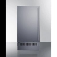
BIM182OS - Ice Maker Summit - Free user manual and instructions
Find the device manual for free BIM182OS Summit in PDF.


| Product type | Under-counter automatic ice maker |
| Brand | Summit |
| Model | BIM182OS |
| Dimensions (W x D x H) | 450 x 575 x 820 mm |
| Weight | 38 kg |
| Power supply | 110-120 V AC, 60 Hz, 15 A |
| Refrigerant | R290 (39 g) |
| Ice production capacity | 60 lbs/24h (27.2 kg/24h) |
| Maximum ice storage | 15 kg |
| Ice cube shape | Cube |
| Ice cube dimensions | 22 x 22 x 22 mm |
| Required water pressure | 15 – 80 PSIG |
| Operating ambient temperature | 10 °C – 38 °C |
| Supply water temperature | 5 °C – 32 °C |
| Main functions | Automatic ice making, automatic harvest, shut-off when bin full, programmable timer, ice size selection (small, medium, large), UV light, interior light |
| Maintenance and cleaning | Clean condenser every 6 months, descale system, clean interior with disinfectant solution (diluted bleach), clean water distributor tube |
| Safety | Grounding required, no extension cord, automatic shut-off if water shortage, door open alarm, compressor protection, use of flammable refrigerant R290 |
| Spare parts and repairability | Parts available through Summit Appliance; repair by qualified technician recommended |
| Warranty | 1 year parts and labor, compressor warranty 5 years (parts only) |
| General information | Designed for under-counter or freestanding installation; requires water supply and drain; adjustable leveling feet; door reversal possible |
Frequently Asked Questions - BIM182OS Summit
Refer to the Installation section of the manual for more details.
User questions about BIM182OS Summit
0 question about this device. Answer the ones you know or ask your own.
Ask a new question about this device
Download the instructions for your Ice Maker in PDF format for free! Find your manual BIM182OS - Summit and take your electronic device back in hand. On this page are published all the documents necessary for the use of your device. BIM182OS by Summit.
USER MANUAL BIM182OS Summit
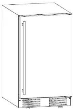
Automatic Undercounter Icemaker
natural_image
Line drawing of a rectangular refrigerator with front panel and side panel (no text or symbols)MODEL
BIM182ADA/ BIM182
BIM182OS/ BIM182OSADA/ LBIM18
DBBIM1863ADA/ DBBIMOS1864ADA
User's Manual
BEFORE USE, PLEASE READ AND FOLLOW ALL SAFETY RULES AND OPERATING INSTRUCTIONS
Be sure icemaker has been standing upright for 24 hours before it is plugged in.
Write Model And Serial Number here:
Model No: ____
Serial No.:
Felix Storch, Inc.
An ISO 9001:2015 registered company
770 Garrison Avenue
Bronx, NY 10474
www.summitappliance.com
TABLE OF CONTENTS
Page
ICEMAKER SAFETY 2
IMPORTANT SAFEGUARDS ....3 - 5
TECHNICAL INFORMATION 6
INTRODUCTION....7
PARTS LOCATIONS....7 - 8
ICEMAKER INSTALLATION....9 - 16
Unpacking....9
Location Requirements 9 - 10
Electrical Requirements 11 - 12
Leveling the Icemaker....12
Water Supply....12 - 13
Drain 14 - 15
Installation Types....16
OPERATION 17 - 21
Final Checklist Before Initial Use....17
Using Your Icemaker....17 - 18
How the Machine Makes Ice....18
How the Machine Uses the Water....19 - 20
Icemaking Diagram....20
Sounds Your Icemaker Makes ....21
Preparing the Icemaker for Vacation 21
CLEANING AND MAINTENANCE 22 - 25
Cleaning the Exterior....22
Cleaning the Interior 23
Cleaning the Condenser 23 - 24
Cleaning the Water Distribution Tube 24
Cleaning the Ice-Making System.... 24-25
CONTROL PANEL....26-27
REVERSING THE DOOR SWING....28-30
INSTALLING THE HANDLE....31
NOTES ABOUT YOUR UNIT 32
TROUBLESHOOTING 32-33
APPENDIX....34-38
NOTES....39
LIMITED WARRANTY....40
We reserve the right to make changes in specifications and design without prior notice.
ICEMAKER SAFETY
Your safety and the safety of others are very important.
We have provided many important safety messages in this manual and on your appliance. Always read and obey all safety messages.
This is the Safety Alert Symbol. This symbol alerts you to potential hazards that can injure or kill you and others.
Safety messages will follow the Safety Alert Symbol and either the words "DANGER", "WARNING" OR "CAUTION".
DANGER means that failure to heed this safety statement may result in severe personal injury or death.
WARNING means that failure to heed this safety statement may result in extensive product damage, serious personal injury, or death.
CAUTION means that failure to heed this safety statement may result in minor or moderate personal injury, or property or equipment damage.
All safety messages will alert you to what the potential hazard is, tell you how to reduce the chance of injury, and let you know what can happen if the instructions are not followed.
IMPORTANT SAFETY INSTRUCTIONS
WARNING: To reduce the risk of fire, electric shock or injury when using your icemaker, follow these basic precautions:
Plug into grounded 3-prong outlet.
Do not remove grounding prong.
Do not use an adapter.
Do not use an extension cord.
• Disconnect power before cleaning.
- Disconnect power before servicing.
- Replace all panels before operating.
- Use two or more people to move & install icemaker.
SAVE THESE INSTRUCTIONS
IMPORTANT SAFEGUARDS
Before the icemaker is used, it must be properly positioned and installed as described in this manual, so read the manual carefully. Our team strongly recommends that you have a professional install your new machine. The warranty may be affected or voided by an incorrect
installation. To reduce the risk of fire, electrical shock or injury when using the icemaker, follow basic precautions, including the following:
! DANGER !
Plug into a grounded 3-prong outlet; do not remove grounding prong, do not use an adapter, and do not use an extension cord.
It is recommended that a separate circuit, serving only your icemaker, be provided. Use receptacles that cannot be turned off by a switch or pull chain.
Do not connect or disconnect the electric plug when your hands are wet.
Never unplug the icemaker by pulling on the power cord. Always grip the plug firmly and pull straight out from the outlet.
Never clean icemaker parts with flammable fluids. Do not store or use gasoline or other flammable vapors and liquids in the vicinity of this or any other appliance. The fumes can create a fire hazard or explosion.
Before proceeding with cleaning and maintenance operations, make sure the power line of the unit is disconnected and the water line is shut off.
Before operating, put all panels back into place.
Never allow children to operate, play with or crawl inside the icemaker.
Do not touch the evaporator with your hand when the machine is operating.
Unplug the icemaker or disconnect power before cleaning or servicing. Failure to do so can result in electrical shock or death.
Do not attempt to repair or replace any part of your icemaker unless it is specifically recommended in this manual. All other servicing should be referred to a qualified technician.
WARNING
Use two or more people to move and install the icemaker. Failure to do so can result in back or other injury.
Never install or operate the unit in an enclosed area, such as a closed cabinet. To ensure proper ventilation for your icemaker, the front of the unit must be completely unobstructed. Choose a well-ventilated area with temperatures above 50^ F ( 10^ C) and below 100^ F ( 38^ C). This unit MUST be installed in an area protected from the elements, such as wind, rain, water spray or drips.
The icemaker should not be located next to ovens, grills, or other sources of high heat. The icemaker must be installed with all electrical and water connections in accordance with state and local codes. A standard electrical supply (110-120V AC, 60 Hz, 15 A), properly grounded in accordance with the National Electrical Code and local codes and ordinances, is required.
Do not kink or pinch the power supply cord between the icemaker and cabinet.
The fuse (or circuit breaker) size should be 15 amperes.
It is important for the icemaker to be leveled in order to work properly. Otherwise, water may not flow properly through the evaporator (ice mold). The ice production will be less than normal. You may need to make several adjustments to level it.
All installations must be in accordance with local plumbing code requirements.
Make certain that hoses are not pinched, kinked, or damaged during installation.
Check for leaks after water line is connected.
Although the unit has been evaluated and cleaned at the factory, due to long-term transit and storage, the first batch of cubes must be discarded.
Remove the packing materials and clean the icemaker before using.
Turn on the water supply tap before switching on the icemaker. Never turn the water supply tap off when the icemaker is working.
Except to take ice from the unit, keep the door closed in order to reduce ice melting and to promote proper ice formation.
If the icemaker will not be used for a long time before the next use it must be thoroughly cleaned. Follow carefully any instructions provided for cleaning or use of sanitizing solution. Do not leave any solution inside the icemaker after cleaning.
Do not touch the condenser fins. They are sharp and can be easily damaged.
DO NOT use solvent-based cleaning agents or abrasives on the interior. These cleaners may transmit taste to the ice cubes, or damage or discolor the interior.
The ice machine cleaner contains acids. Do not use or mix with any other solvent-based cleaning products. Use rubber gloves to protect hands. Carefully read the safety instructions on the container of the ice machine cleaner.
Do not use the apparatus other than for its intended purpose.
Children should be supervised to ensure that they do not play with the appliance.
Do not store explosive substances such as aerosol cans with a flammable propellant in this appliance.
WARNING: Keep clear of obstruction to all ventilation openings in the appliance enclosure or in the structure for building-in.
WARNING: Do not use mechanical devices or other means to accelerate the defrosting process, other than those recommended by the manufacturer.
WARNING: Do not damage the refrigerating circuit.
WARNING: Do not use electrical appliances inside the food/ice storage compartments unless they are of the type recommended by the manufacturer.
If the SUPPLY CORD is damaged, it must be replaced by the manufacturer, its service agent, or similarly qualified persons in order to avoid a hazard.
ENVIRONMENT
This product use FLAMMABLE REFRIGERANTS, at the end of its life, the appliance should be recycled separately from other domestic waste.
It should therefore be disposed of at a selective collection center for electrical and/or electronic appliances or, if you are buying an equivalent product, by the retailer of the new product.
The user is responsible for taking the appliance to the appropriate collection center at the end of its useful life. Selective and appropriate collection for the recycling of no-longer-used appliances and their disposal and destruction in an environmentally friendly manner helps to prevent potential negative effects on the environment and health and encourages the recycling of materials used to make the product.
For more detailed information about available collection systems. contact your local waste collection organization or the retail outlet where you bought the product.
SAVE THESE INSTRUCTIONS
Electrical Connection
Do not, under any circumstances, cut or remove the third (grounding) prong from the power cord. For personal safety, this appliance must be properly grounded. The power cord of this appliance is equipped with a 3-prong grounding plug that mates with a standard 3-prong grounding wall outlet to minimize the possibility of electric shock hazard from the appliance. Have the wall outlet and circuit checked by a qualified electrician to make sure the outlet is properly grounded. When a standard 2-prong wall outlet is encountered, it is your responsibility and obligation to have it replaced with a properly grounded 3-prong wall outlet. The icemaker should always be plugged into its own individual electrical outlet which has a voltage rating that matches the rating label on the appliance. This provides the best performance and also prevents overloading house wiring circuits which could cause a fire hazard from overheated wires.
Never unplug your icemaker by pulling on the power cord. Always grip the plug firmly and pull it straight out from the outlet. Repair or replace immediately all power cords that have become frayed or otherwise damaged. Do not use a cord that shows cracks or abrasion damage along its length or at either end. When moving the icemaker, be careful not to damage the power cord.
Extension Cord
Because of potential safety hazards under certain conditions, it is strongly recommended that you do not use an extension cord with this icemaker.
UV Light
This appliance contains a UV light.
- Unintended use of the appliance or damage to the housing may result in the leakage of dangerous UV-C radiation, UV-C radiation may, even in small doses, cause harm to the eyes and skin.
- Appliances that are damaged must not be operated
- Read the maintenance instructions before opening the appliance.
- The appliance must be disconnected from the supply before replacing the UV light.
WARNING: UV radiation is dangerous for the eyes and skin. Do not operate the UV-C emitter outside the appliance.
The Fire Symbol
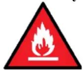
This symbol shows that this appliance uses a flammable refrigerant. If the refrigerant is leaked and exposed to an external ignition source, there is a risk of fire.
TECHNICAL INFORMATION
| INDOOR and OUTDOOR | |
| Model: | BIM182ADA (see additional model numbers on cover) |
| Electrical power: | 110-120V AC ~ 60Hz |
| Power consumption: | 11.8 kWh/ 100 lbs. of ice |
| Ice-making /-harvest rated current: | 2.8A |
| Refrigerant | R290,1.37oz (39g). |
| High/Low side pressure: | 330 PSIG/160 PSIG |
| Width x depth x height: | 450 x 575 x 820 mm / 17.7” x 22.63” x 32.28” |
| Unit weight: | 38 kg / 84 lbs. |
| Maximum ice storage: | 15 kg / 33 lbs. |
| Ice-making capacity: | 60 lbs. ice/24h* |
| Ice shape: | Cube |
| Ice cube dimension | 22 x 22 x 22 mm / .87” x .87” x .87” |
The technical data and performance index listed above should be used for reference only. They are subject to change.
*The actual quantity of ice produced per day can vary with room and water conditions.
Climate class
The climate class of the appliance is 4. The meaning of Class 4 as below:
| Test room climate class | Dry bulb temperature °C (F°) | Relative humidity % | Dew point °C (F°) | Water vapor mass in dry air g/kg |
| 4 | 30/86 | 55 | 20.0/68.0 | 14.8 |
INTRODUCTION
This icemaker produces hard, crystal-clear, gourmet cube ice and offers convenience for homeowners and hotel guests. It comes with a built-in insulated ice storage bin. This unit must be operated with an external drainage system.
This user's manual is intended as a resource for the persons installing, using, and servicing this icemaker. It contains valuable information on safety and maintenance. Our team strongly recommends that the manual be kept in a place where it can be easily accessed when needed.
This icemaker is designed and manufactured according to the highest standards of safety and performance. It meets or exceeds the safety standard of UL 60335-1, 60335-2-89 and 60335-2-24.
Our team assumes no liability or responsibility of any kind for products manufactured by SUMMIT that have been altered in any way, including the use of any parts and/or other components not specifically approved by SUMMIT. Our team reserves the right to make design changes and/or improvements at any time. Specifications and designs are subject to change without notice.
PARTS LOCATIONS
Parts should be replaced with similar parts to minimize the risk of possible ignition due to incorrect parts.
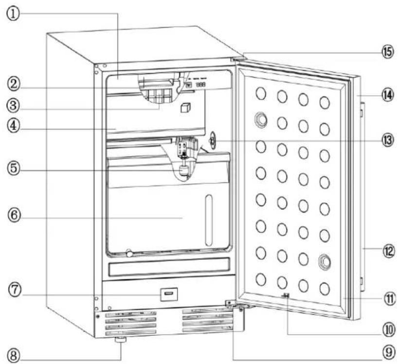
| 1 | Control panel |
| 2 | Water distribution tube |
| 3 | Evaporator (ice mold) |
| 4 | Baffle |
| 5 | Float |
| 6 | Ice storage bin |
| 7 | Mechanical switch (UV light) |
| 8 | Adjustable feet |
| 9 | Lower hinge |
| 10 | Mechanical switch (UV light) |
| 11 | Door gasket |
| 12 | Handle |
| 13 | UV light |
| 14 | Door |
| 15 | Upper hinge |
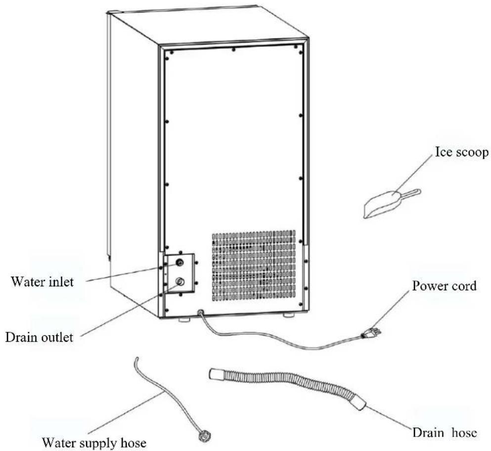
ICEMAKER INSTALLATION
The appliance is to be installed in accordance with the Safety Standard for Refrigeration Systems, ANSI/ASHRAE 15
Unpacking

WARNING
Excessive Weight Hazard
Use two or more people to move and install the icemaker. Failure to do so can result in back or other types of injuries.
Removing packaging materials.
IMPORTANT: Do not remove any permanent instruction labels or the rating label on your icemaker.
Remove tape and glue from your icemaker before using it for the first time.
To remove any remaining tape or glue, rub the area briskly with your thumb. Tape or glue residue can also be easily removed by rubbing a small amount of liquid dish soap over the adhesive with your fingers. Wipe with warm water and dry.
Do not use sharp instruments, rubbing alcohol, flammable fluids, or abrasive cleaners to remove tape or glue. These products can damage the surface of your icemaker.
Cleaning before use
After you remove all of the packaging materials, clean the inside of your icemaker before using it. See "Interior cleaning" in the Cleaning and Maintenance section.
Location Requirements
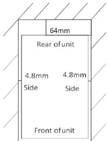
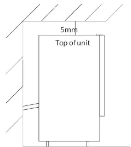
INSTALLATION CLEARANCES:
TOP VIEW SIDE VIEW
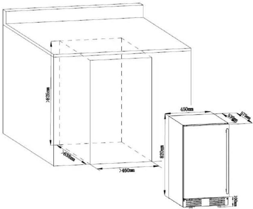
This icemaker should be professionally installed by qualified personnel.
To ensure proper ventilation for your icemaker, the front of the unit must be completely unobstructed.
When installing the icemaker under a counter, follow the recommended spacing dimensions shown. Allow at least 64 mm (2.5") clearance at the rear, 5 mm (.2") at the top, and 4.8 mm (.2") at the sides for proper air circulation. The installation should allow the icemaker to be pulled forward for servicing if necessary.
Choose a well-ventilated area with room temperatures within the normal range. This unit MUST be installed in an area protected from the elements, such as wind, rain, water spray or drips.
The unit should not be located next to ovens, grills, or other high heat sources.
Installation of the icemaker requires a cold water supply inlet of 6.35mm soft copper tubing with a shut-off valve.
The icemaker requires a continuous water supply with a minimum pressure of 15 PSIG and a static pressure not to exceed 80 PSIG. The temperature of the water feeding into the icemaker should be between 41^ (5°C) and 90^ (32°C) for proper operation.
WARNING
Operating temperature should be within the range of normal room temperatures. Normal operating water temperature should be between 41^ F ( 5^ C) and 90^ F ( 32^ C). Operation of the icemaker for extended periods outside of these normal temperature ranges may affect production capacity.
We strongly recommend that a water filter be used. A filter, if it is of the proper type, can remove taste and odors as well as particles. Some water can be very hard, and softened water may result in white, mushy cubes that stick together. Deionized water is not recommended.
The icemaker must be installed with electrical and water connections in accordance with all state and local codes.
The unit should be located on a firm and level surface. The icemaker needs to be leveled to work properly. If needed, you can adjust the height of the icemaker by adjusting the caster. See the Leveling the Icemaker section.
A standard electrical supply (110V AC only, 60Hz, 15A), properly grounded in accordance with the National Electrical Code and local codes and ordinances, is required.
IMPORTANT: Do not kink or pinch the power supply cord between the icemaker and the wall or cabinet.
Electrical Requirements
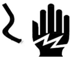
! DANGER !
natural_image
Two black electrical hazard symbols: a curved line and a lightning bolt symbol (no text or labels)Electrical Shock Hazard
Plug into a grounded 3-prong outlet.
Never remove the ground prong from the plug.
Never use an adapter.
Never use an extension cord.
Failure to follow these instructions can result in fire, electrical shock, or death.
Before you move your icemaker into its final location, it is important to make sure you have the proper electrical connection.
A standard electrical supply (110V AC only, 60Hz, 15A), properly grounded in accordance with the National Electrical Code and local codes and ordinances, is required. The icemaker should always be plugged into its own individual electrical outlet.
It is recommended that a separate circuit, serving only your icemaker, be provided. Use a receptacle that cannot be turned off by a switch or pull chain.
The fuse (or circuit breaker) size should be 15 amperes.
Recommended grounding method
For your personal safety, this appliance must be grounded. This appliance is equipped with a power supply cord having a 3-prong grounding plug. To minimize possible shock hazard, the cord must be plugged into a mating 3-pronged and grounding-type wall receptacle, grounded in accordance with the National Electrical Code and local codes and ordinances. If a mating wall receptacle is not available, it is the personal responsibility of the customer to have a properly grounded, 3-prong wall receptacle installed by a qualified electrician.
Leveling the Icemaker
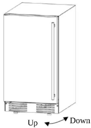
It is important for the icemaker to be leveled in order to work properly. Otherwise, water will not flow properly through the evaporator (ice mold). The ice production will be less than normal, and may be noisy. The unit can be raised or lowered by rotating the four adjustable feet on the bottom of the machine. If you find that the surface is not level, rotate the feet until the icemaker becomes level. You may need to make several adjustments to level it. We recommend using a carpenter's level to check the machine
natural_image
Line drawing of a refrigerator with labeled 'Up' and 'Down' arrows indicating front and back sides (no text or symbols on the device itself)-
Place a carpenter's level on top of the unit to see if the icemaker is level from front to back and side to side.
-
Adjust the height of the adjustable feet as follows:
Turn the leveling feet to the right to lower that side of the icemaker.
Turn the leveling feet to the left to raise that side of the icemaker.
You will find that the feet make it easy for one person to move the machine. This is useful for cleaning and sanitizing the surface on which the icemaker is installed because it allows you to move the unit and have easy access to the surface to be cleaned.
IMPORTANT: When the icemaker is ready to be installed in a cabinet or directly on the floor, you must adjust the feet to level the icemaker and lock the rollers. If the floor is level, just adjust the two front feet until they touch the floor.
Water Supply
The water supply should be ready at the point of installation. The water supply pressure should be a minimum of 15 PSIG with a static pressure no greater than 80 PSIG. (A wall outlet directly behind the ice machine will make installation easier.)
IMPORTANT:
- All installations must be in accordance with local plumbing code requirements. Professional installation is recommended.
- Make certain the hoses are not pinched kinked or damaged during installation.
- Check for leaks after connection.
Tools required:
12mm open-end wrench, Phillips screwdriver
Connecting the water line:
- Turn off the main water supply. Turn on the nearest faucet long enough to clear line of water.
- Find a 12mm to 19mm vertical cold water pipe near the installation location. The distance should be less than 3m. The water supply hose provided with the icemaker is about 3m long.
- A shut-off valve must be installed to the main water supply. If the water pipe has a plain piece of copper tubing, attach a 19mm O.D. compression union to the tubing and remove the nut.
- Connect the nut of the water supply hose to the tap and connect the other end with the water inlet. Tighten firmly by hand, then one-half turn with wrench.
- Turn on main water supply and tap. Check for water supply connection leaks. Tighten every connection (including connection at the water inlet).
IMPORTANT: When you connect the water supply hose and the drain hose, pay attention to the indications of “Water inlet” and “Drain outlet” on the machine.
Drain
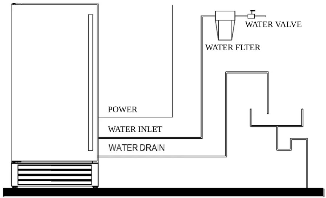
You must connect the drain line before using the icemaker. Follow the steps below.
There are two types of ice machine modes, one that drains by gravity and one that has an internal drain pump.
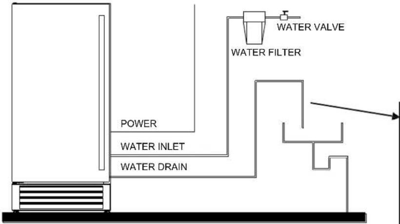
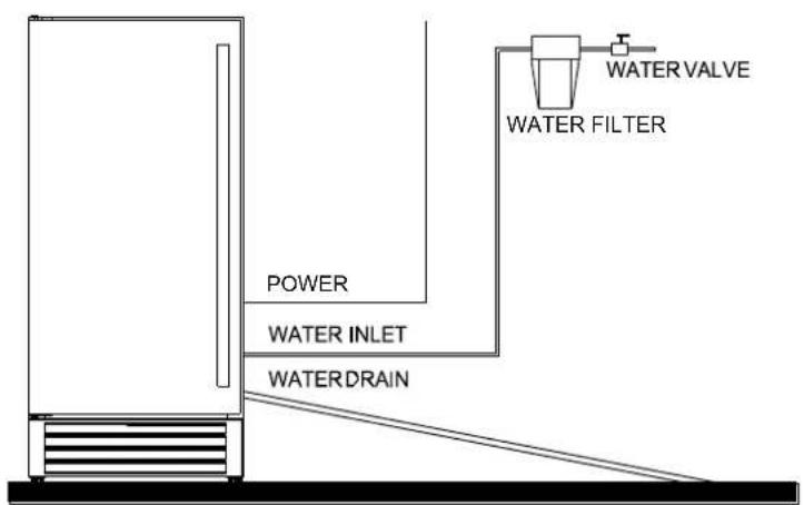
This unit can pump out water up to a rise of 1.5m (5ft)
flowchart
graph TD
    A["Power"] --> B["WATER INLET"]
    B --> C["WATER DRAIN"]
    C --> D["Water FLTER"]
    D --> E["WATER VALVE"]
or over a horizontal length of 1.5m (5ft).
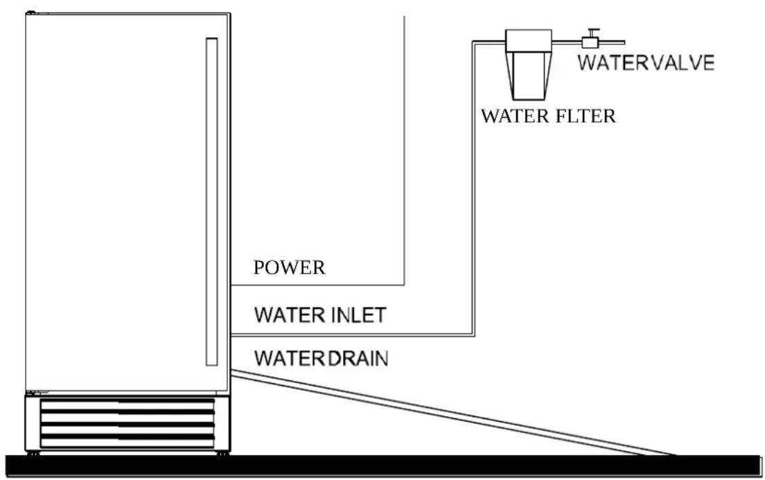
Connecting the drain line:
NOTE: If there is a drain line near the icemaker, the best choice is to drain water to the drain line through the drain water hose provided with icemaker.
- Locate the floor drain near the icemaker. The distance should be less than 2m since the length of the long drain water hose provided with the ice is about 2m.
- Find the drain outlet on the back of icemaker. Connect the water draining hose to the drain outlet and insert the other end of the hose into the drain line.
NOTE: Never allow the drain hose to hang or loop higher than the floor of the ice storage bin.
-
All horizontal runs of drain lines must have a fall of 6.35mm per foot. An air gap will likely be required between the icemaker drain tube and the drain/waste receptacle. A standpipe with a trap below it would be acceptable for the drain/waste receptacle. A floor drain is also acceptable. If this is not possible, the use of the condensate pump is recommended.
-
Pour 3.7L (1 gallon) of water into the ice storage bin to check for leaks in the drainage system. Tighten any connections that leak.
IMPORTANT: This icemaker is not a freezer. Infrequent drainage will cause a high rate of melting in the ice storage bin.
Installation Types
This icemaker has been designed for free-standing installations. However, it can also be installed under a cabinet or built in.
Free-standing installation:
A free-standing installation will allow you to install the icemaker in any place you desire provided you have access to a water supply. You must follow the stated instructions for
a. Electrical requirements
b. Water supply
c. Leveling the icemaker.
Enclosed Installation:
An enclosed installation will allow you to install the icemaker under a cabinet or in a kitchen cabinet provided the required clearance space around the icemaker is followed. This installation has the same requirements as a free-standing installation.
Built-in installation:
If this method of installation is chosen, it will still be necessary to allow adequate ventilation space around the unit. The following additional items must be observed.
- Place icemaker in front of the installation location. Remove the feet and place the unit flat on the floor or a platform depending on your installation requirements.
- The water supply line must be plumbed before connecting to the icemaker.
- Turn on the main water supply and the tap. Check for water supply connection leaks. Tighten every connection (including connection at the water inlet).
- If the electrical outlet for the icemaker is behind the cabinet, plug in the icemaker.
- Push the icemaker into position.
- Using an approved caulking compound, seal all around the edges of the cabinet floor.
IMPORTANT: Be sure the drain hose is connected and fed into the drain line before the icemaker is moved into its final position.
OPERATION
Final Check List Before Initial Use
- Have all packing materials and tape been removed from the interior and exterior of the icemaker?
- Did you clean the ice storage bin?
- Were the installation instructions followed, including connecting the machine to water and electricity?
- Has the machine been leveled?
- Is the icemaker in a site where the ambient temperature is within the range of normal room temperatures and the water temperature between 41^ F ( 5^ C) and 90^ F ( 32^ C) all year round?
- Has the water supply pressure been checked to ensure a minimum of 15 PSIG with a static pressure not to exceed 80 PSIG?
- Is there a clearance of at least 35 mm at the rear, 5 mm at the top, and 4.8 mm at the sides for proper air circulation?
- Has the power supply voltage been checked or tested against the electrical data on the rating label? And has proper grounding been installed in the icemaker?
- Is the icemaker plugged in?
- Have you turned on the main water supply and tap?
- Have you checked for leaks at all water supply connections?
Using Your Icemaker
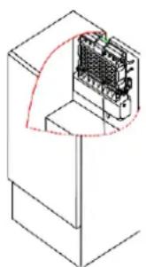
- Turn on the water tap, let the water trough fill, then press the ON/OFF button on the front panel. The icemaker will start working automatically.
During the initial set-up, the icemaker will flush itself for 10 seconds, at which time the cleaning indicator on the panel will light up and the wastewater will be discharged into the wastewater tank.
natural_image
Isometric line drawing of a mechanical or electronic component with a red curved arrow indicating direction (no text or symbols)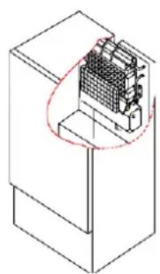
natural_image
Isometric technical drawing of a mechanical component with internal grid structure (no text or symbols)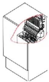
natural_image
Isometric line drawing of a mechanical component with internal structure (no text or symbols)Ice making stage Ice harvesting stage Bin is full
-
After the flushing is complete, the machine will automatically enter the ice-making stage, and the sound of water flowing will be heard.
-
When a batch of ice has been fully formed, ice will automatically be harvested to the ice storage bin.
-
When the ice storage bin is full, the sheet of cubes will not fall completely and will hold the bin-full probe open. The machine will stop making ice automatically.
-
Once the ice cubes are removed, the full bin probe will swing back to its operational position Then, the unit will start making ice again after 3 minutes.
-
Top light: The top light is controlled by a magnetic reed switch that has been installed on the inner surface of the door. It is turned on or off automatically with the opening or closing of the door.
-
Pump Water Drain System (if used): When the water in the wastewater tank or other remaining overflow water reaches the maximum water level, the drainage pump starts to discharge the wastewater into the wastewater tank.
IMPORTANT:
Although the unit has been evaluated and cleaned at the factory, due to long-term transit and storage, the first batch of cubes must be discarded.
Never turn the water supply tap off when the icemaker is working.
Never touch the evaporator when the unit is running!
Unless you are taking ice from the unit, keep the door closed to reduce melting and ensure proper ice formation.
How The Machine Makes Ice
Set the ON/OFF button to the ON position. The machine will automatically go to the ice-making stage.
There are two distinct cycles: ice freeze and harvest.
The freeze cycle happens when water flows to the evaporator surface. The harvest cycle is when the ice is released, and water enters the machine. A complete cycle takes about 20 minutes, but it depends on temperature and operating conditions.
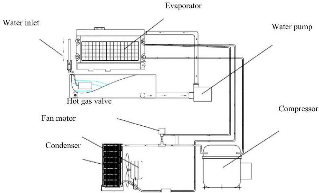
Freeze: During the freeze cycle the compressor is pumping refrigerant, the fan motor is blowing air, and the water pump is circulating water. When the batch of ice has been fully formed, the icemaker stops the freeze cycle, and the harvest cycle begins.
Harvest: During the harvest cycle the compressor is still operating, but the water pump has stopped. The hot gas valve opens, diverting hot refrigerant gas into the evaporator. The hot refrigerant gas warms the evaporator, causing the cubes to slide as a unit off the evaporator and into the storage bin. The freeze cycle will restart when all the cubes have been harvested.
How The Machine Uses the Water
The icemaker begins with a fixed charge of water that is contained in the water trough. As the water flows to the freezing evaporator surface, the portion of water that does not contain mineral impurities freezes and sticks to the ice cube molds. The water containing impurities falls back into the water trough. During the ice making process, fresh water enters into the water trough continuously as the water in the trough freezes continuously in the evaporator.
How The Drain System Operates When Water Is Pumped Out
The components of the Pump-Out Water Drain System are
Water reservoir
PC Board & Water level switch 1, 2
Water Drain Pump
OPERATION
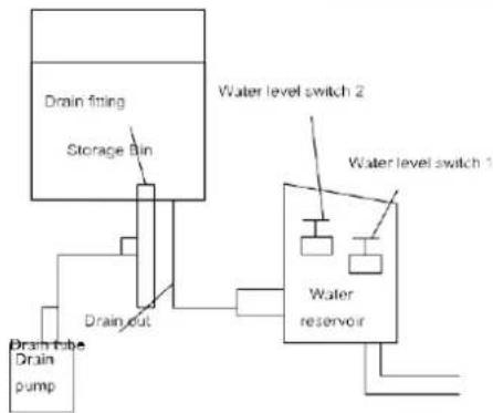
All water coming from the overflow and the melted ice is collected in the water reservoir.
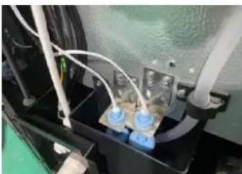
As soon as the water in the reservoir reaches the maximum level, the water level switch 1 closes, transmitting a low voltage current to the PC Board.
natural_image
Close-up of a mechanical or electrical component with blue and white components, no visible text or symbols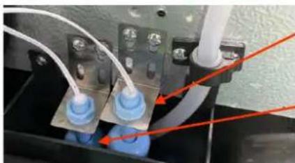
natural_image
Close-up of industrial piping and electrical components with blue connectors and white cables (no visible text or symbols)Water level switch 2
Water level switch 1
The PC board activates the water drain pump for 10 seconds, pumping out most of the water contained in the water reservoir.
The water can be pumped out up an incline of 1.5m or over a horizontal length of 1.5m.
flowchart
graph TD
    A["Power"] --> B["WATER INLET"]
    B --> C["WATER DRAIN"]
    C --> D["Water FILTER"]
    D --> E["WATER VALVE"]
natural_image
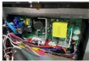
Interior view of an electronic device showing exposed circuit board, wires, and components (no visible text or symbols)NOTE:
The outlet of the drain hose must be raised higher than the water surface to prevent the drained water from flowing back into the water reservoir.
If water level switch 2 closes, it transmits a low-voltage current to the PC board, the PC board activates the buzzer alarm, informing you that the drain pump, water level switch, or drain tube may be malfunctioning.
WARNING!
If the alarm goes off, turn off the icemaker and the water supply, remove all ice from the storage bin and wipe up any water that may have overflowed. Check if there is any water in the water trough at the back of the unit; if there is no water, the drainage pump may not be receiving the proper amount of power. Check the power source. If the problem has been corrected, turn on the unit again. Also, check that none of the water lines are kinked. If the problem remains, contact SUMMIT Customer Service.
Icemaking Diagram
flowchart
graph TD
    A["Drain tube Drain pump"] --> B["Drain out"]
    B --> C["Storage Bin"]
    C --> D["Drain fitting"]
    D --> E["Water level switch 1"]
    E --> F["Water level switch 2"]
    F --> G["Water reservoir"]
    G --> H["Ground"]
Sounds Your Icemaker Makes
Your new icemaker may make sounds that are not familiar to you. Most of the sounds are normal. Hard surfaces like the floor and walls can make the sounds seem louder than they are. The following list describes the sounds that might be new to you and what may be causing them.
Rattling noises may come from the flow of the refrigerant or the water line. Items stored on top of the icemaker can also make noises.
The high-efficiency compressor may make a pulsating or high-pitched sound.
Running water may make a splashing sound.
You may hear air being forced over the condenser by the condenser fan.
During the harvest cycle, you may hear the sound of ice cubes falling into the ice storage bin.
You will occasionally hear the sound of the drain pump operating.
Preparing the Icemaker for Vacation
If the icemaker will not be used for a long time or is to be moved to another place, it will be necessary to drain the system of water.
- Shut off the water supply at the main water source.
- Disconnect the water supply line from the water inlet.
- Shut off the electric supply at the main electrical power source.
- Take out the ice storage bin to remove any remaining ice and water. Dry the bin.
- Pull the drainage tube from the water trough to drain all the water.
- Leave the door open to allow for circulation and to prevent mold and mildew.
- Leave the water supply line and power cord disconnected until ready to reuse.
IMPORTANT:
Do not touch the power plug when your hands are wet.
Never unplug the unit by pulling on the cord. Grasp the plug and pull out firmly.
CLEANING AND MAINTENANCE
If the icemaker is left unused for a long time, it must be thoroughly cleaned before the next use. Carefully follow any instructions provided for cleaning or the use of sanitizing solutions. Do not leave any solution inside the icemaker after cleaning.
Periodic cleaning and proper maintenance will ensure efficiency, top performance, and a long life for your life. The maintenance intervals listed are based on normal conditions.
You may want to shorten the intervals if you have pets, or if there are other special considerations.
NOTE:
Never keep anything in the ice storage bin that is not ice: objects like wine and beer bottles are not only unsanitary, but the labels may slip off and plug up the drain.
Parts to Keep Clean
There are 5 things to keep clean:
- The exterior
- The interior
- The condenser
- Water distribution tube
- The ice-making system
Before proceeding with cleaning and maintenance operations, make sure the power line of the unit is disconnected and the water line is shut off.
Cleaning the exterior
The door and cabinet may be cleaned with a mild detergent and warm water solution such as 30ml (1 oz.) of dishwashing liquid mixed with 7.5L (2 gallons) of warm water. Do not use solvent-based or abrasive cleaners. Use a soft sponge and rinse with clean water. Wipe with a soft, clean towel to prevent water spotting.
If the door panel is stainless steel, stainless steel can discolor when exposed to chlorine gas and moisture. Clean stainless steel with a mild detergent and warm water solution and a damp cloth. Never use an abrasive cleaning agent.
Cleaning the Interior
The ice storage bin should be sanitized occasionally. Clean the water trough before the icemaker is used for the first time and reused after stopping for an extended period of time. It is usually convenient to sanitize the trough after the ice making system has been cleaned and the ice storage bin is empty.
- Disconnect the power to the unit.
- Open the door and take out the removable ice storage bin. With a clean cloth, wipe down the interior of unit and ice bin with a sanitizing solution made of 30ml (1 ounce) of household bleach or chlorine and 7.5L (2 gallons) of hot (95°F – 115°F) water.
- Pull off the soft plug of drain hose of the water trough to drain off all water.
- Rinse thoroughly with clear water.
- After draining off all water, put back the soft plug of drain hose of the water
trough into the original location.
-
Put the ice storage bin inside the unit.
-
Reconnect power to the unit.
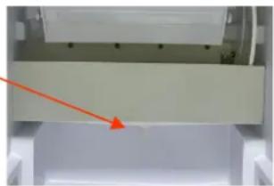
Correct location of the drain hose
natural_image
Close-up of a white mechanical component with a red arrow pointing to a small rectangular area (no visible text or symbols)The ice scoop should be washed regularly. Wash it just like any other food container.
WARNING
DO NOT use solvent-based cleaning agents or abrasives on the interior. These cleaners may transmit taste to the ice cubes and damage or discolor the interior.
Cleaning the Condenser
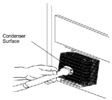
A dirty or clogged condenser prevents proper airflow, reduces ice-making capacity, and causes higher than recommended operating temperatures that may lead to component failure. Have the condenser cleaned at least once every six months.
- Unplug the icemaker or disconnect the power.
- Gently pull off the lower front grille.
- Remove dirt and lint from the condenser and the unit compartment with the brush attachment of a vacuum cleaner.
- Reassemble the lower front grille.
- Plug in the icemaker or reconnect power.

WARNING
DO NOT touch the condenser. Edges are sharp and can be easily damaged.
Cleaning the Water Distribution Tube
If you find the ice cubes are incompletely formed or the output is low, the water distribution tube may be blocked. Turn off the unit, gently take out the water distribution tube, locate the holes in the distribution tube, and use a pointed object such as a toothpick to dredge the holes. Then put the water distribution tube back in its original position. If the tube is heavily blocked, clean it as follows:
- Shut off the water supply
- Disconnect the water hose from the distribution tube.
- Gently take out the distribution tube.
- With a brush, clean the tube with a diluted solution of warm water and a mild detergent such as dishwashing liquid. After removing the dirt and lint from the surface, rinse the tube with clean water.
- Reinstall the distribution tube.
- Reconnect the water supply.
Cleaning the Ice-making System
Minerals that are removed from the water during the freezing cycle will eventually form a hard, scaly deposit in the water system. Cleaning the system regularly helps remove the mineral scale buildup. How often to clean the system depends upon how hard your water is or how effective your filtration may be. If the hard water is of 15 to 20 grains/gal. (4 to 5 grains/ liter), you may need to clean the system as often as once every 6 months.
-
Make sure that all the ice cubes are removed from the evaporator. If the machine is in the ice making process, wait until the deicing is complete, and then press the
On/Pause/Off button to pause the icemaker. At this time, the display will show P.
If you do not want to wait, press and hold the UV and Timer buttons for 3 seconds to enable the manual deicing, at this time the digital screen will display FF, look at the ice on the ice mold, if the ice has been cleaned, press and hold the UV and Timer button for 3 seconds again to exit the manual deicing, after exiting the manual deicing, it will automatically pause again, the display will again show P.
While manual deicing, if the ice is thicker than normal and the deicing switch is triggered, the manual deicing process will stop and will return to the paused state. -
Open the door and take out all the ice in the ice storage bin.
- Keep the icemaker connected to the water supply, pour in a Nickel-Safe icemaker cleaning solution, then press the Clean button, and the machine will automatically
operate in cleaning mode. After 20 minutes of cleaning, the water will automatically be discharged from the wastewater tank. After completion, the ice machine will automatically revert to the paused state
- Press Clean button again and rinse thoroughly with clear water. NOTE: Do not drain the wastewater to the inside of the cabinet.
NOTE: Icemaker Cleaner Solution in the water bin while rinsing is not needed.
The ice machine cleaner contains acids.
DO NOT use or mix with any other solvent-based cleaner products.
Use rubber gloves to protect hands. Carefully read the safety instructions on the container of the ice machine cleaner.
Discard the first batch of ice produced after cleaning.
- Prepare a sanitizing solution made of 1 ounce of household bleach and 2 gallons of hot water (95°F to 115°F). Wipe the entire bin inside and outside, covering the entire surface of the walls.
- Fill a spray bottle with the sanitizing solution and spray all corners and edges, making sure to cover all surfaces with the solution.
- Allow the solution to rest for at least 3 minutes, then dry.
- Repeat step 4 to rinse the ice-making system one more time.
- Press the On/Pause/Off button again. The machine will return to the regular ice-making mode. Discard the first batch of ice.
Control Panel:

Description of LEDs and buttons:
- Bin Full LED: Full bin indicator light
When this is lit, the ice storage bin is full of ice, or something is blocking the full bin probe. The unit will stop working. When ice cubes are removed from the ice storage bin, freeing the full bin probe, the LED will turn off automatically, then the unit will restart and return to ice-making mode.
- Ice Making LED: Ice making indicator light
When this is lit, the unit is in ice-making mode, which is controlled by a temperature probe on the evaporator. When this LED is flashing, the unit is in ice-making mode but controlled by a fixed timer.
- Water LED: Insufficient water indicator light
When this is lit and the alarm sounds, there is not enough water in the water trough. The LED will light up and the alarm will go off when the water inlet valve has been opened for 6 minutes and the water float does not move. Press any button to shut off the alarm. The alarm will automatically shut off once the float in the water trough floats up to the OFF position. While in this state, the unit will open the water inlet valve for 1 minute and then close it for 1 minute until the alarm is turned off or the issue is fixed and water flows through the valve again.
-
On/Pause/Off button:
-
Press to start the ice making process, the LED will flash to signify it is starting the process after there has been no additional input for 5 seconds.
- Press the button again to pause the process, the LED will flash.
-
Press and hold for 3 seconds to power off.
-
Clean button:
-
Press Clean to enter cleaning mode, the icemaker will start cleaning after the LED flash for 5 seconds. After 3 cycles of cleaning, it will automatically exit cleaning mode and return to ice making, and the LED will turn off.
While in cleaning mode, press Clean for 3 seconds to force the unit to exit cleaning mode. - If Clean is pressed during the ice making process, the cleaning process will start after the end of deicing.
6. Ice size button:
Press Ice Size to select the size of the ice. The button can cycle between the three available sizes: large, medium, and small. The corresponding LED showing the chosen size will light up
NOTE: The factory default setting is medium.
7. UV button:
- Press the button to turn on the UV light, the LED will turn on. Press it again to turn off the UV light. The UV light automatically turns on when the door closes and turns off when the door is opened.
- Press and hold UV button for 3 seconds to toggle on or off the logo light.
8. Timer button:
- Press and hold the Timer button for 3 seconds to enter Timer Mode. The digital display will show you the timer to start the icemaking operation or to stop it (Depending on if you choose Timer Off or Timer On). The timer's range can span from 1 hour to 24 hours. Each press of the button deducts 1 hour from the timer. After 3 seconds with no input, the LED will stop blinking and the settings will be confirmed. If you wish to adjust the settings again, press the Timer button again.
Timer on (LED): When the icemaker is powered off, press, and hold the Timer button for 3 seconds until the Timer On LED turns on. The digital display will show the timer until the unit starts operation. The factory default is 12 hours, but that can be adjusted to your preference. If you wish to exit the timer setup, press Timer for 3 seconds.
Timer Off (LED): When the icemaker is powered on or paused, press the Timer button for 3 seconds. The Timer On LED will light up and the digital display will show the timer until the unit shuts down. The factory default is 12 hours but that can be adjusted to your preference. If you wish to exit the timer setup, press Timer for 3 seconds.
Alarm and Error codes:
-
L1: Evaporation sensor failure: Press any buttons to stop the alarm
-
L2: The ambient temperature sensor is faulty: Press any buttons to stop the alarm
-
E1: Deicing failure: Press any buttons to stop the alarm
-
E2: Drainage failure: Press any buttons to stop the alarm
-
E3: Cleaning fault: The alarm is on, but the icemaker keeps ice making process,
-
E4: Refrigeration failure
-
E5: Door opening alarm: The alarm will stop when door closed or press any button to stop the alarm.
Manual de-icing
Press UV and Timer for 3s to start manual de-icing function, the digital screen will display “FF”. Press UV and Timer for 3s again to stop the manual deicing function, and the icemaker stops making ice and digital screen display “P”. Press On/Paus/Off to start making ice again.
REVERSING THE DOOR SWING
(Note: select options, such as custom handles, may not allow the door to be reversed post-purchase. Consult our website for more information)
The left upper hinge and the left lower hinge are packaged in the accessories bag. Save them in case you wish to reverse your door's swing.
The icemaker's door is mounted on the right hinge by default. If you wish, you can change it to the left hinge by following the instructions below:
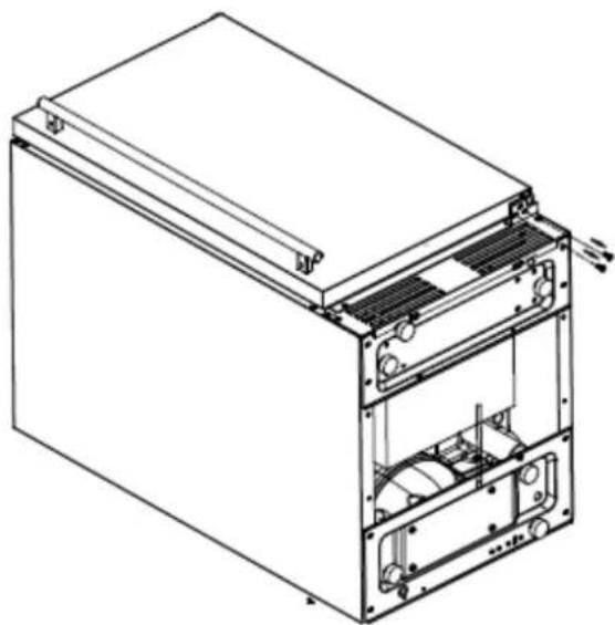
- Place the unit on its back and on a soft surface.
- Remove the screw on the lower hinge.
natural_image
Technical line drawing of a multi-chamber electronic device with internal components (no text or symbols)-
Remove the door and place it on a soft surface.
-
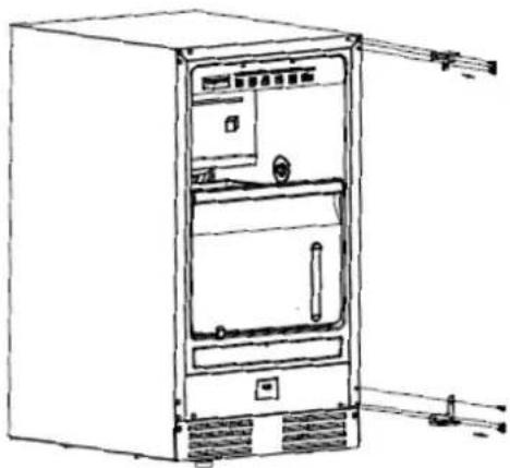
Remove the right upper and lower hinge.
natural_image
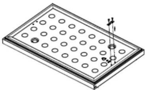
Line drawing of a refrigerator with doors, front panel, and side door (no text or symbols)- Remove the UV magnetic switch on the door and save for Step 9.
natural_image
Isometric technical drawing of a perforated plate with circular holes and a small cylindrical component inserted (no text or symbols)- Rotate the door by 180^
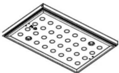
natural_image
Isometric view of a rectangular tray with circular indentations and a side tab (no text or symbols)- Take out the hinges that were included in the manual bag and attach the upper and lower hinge to the left side of the unit.
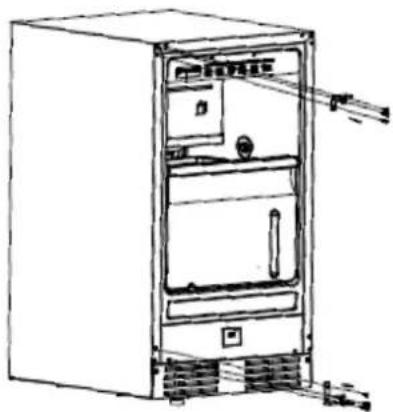
natural_image
Line drawing of a refrigerator with doors, front panel, and side-mounted legs (no text or symbols)- Install the door on the product and affix the screws.
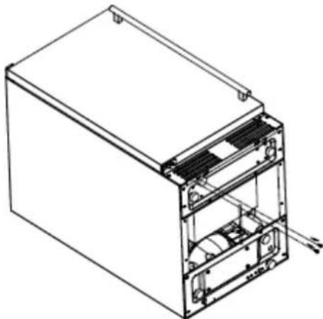
natural_image
Technical line drawing of a mechanical device with internal components and mounting brackets (no text or symbols)- Install the UV magnetic switch on the door.
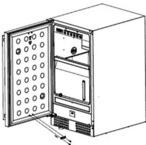
natural_image
Line drawing of an open refrigerator with circular vent slots and internal compartments (no text or symbols)INSTALLATING THE HANDLE.
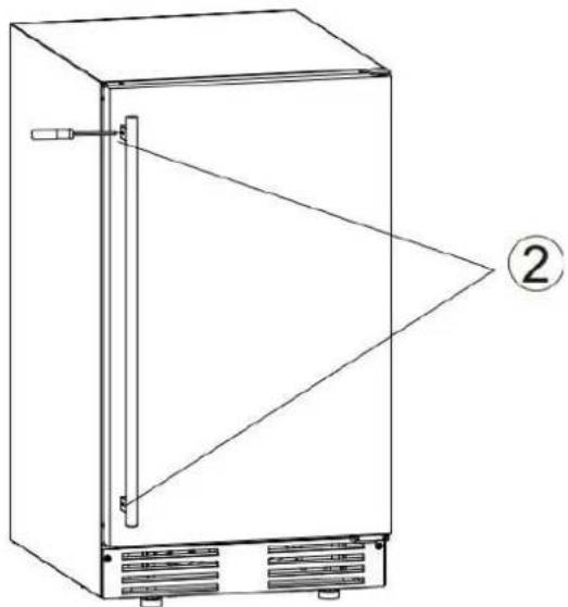
The handle's mounting stubs and screwdriver are packaged in the accessories bag. Save them in case you need to remove the handle.
This icemaker comes with a stainless steel handle, follow the instructions below to install it:
- Install the handle's mounting stubs on the door.
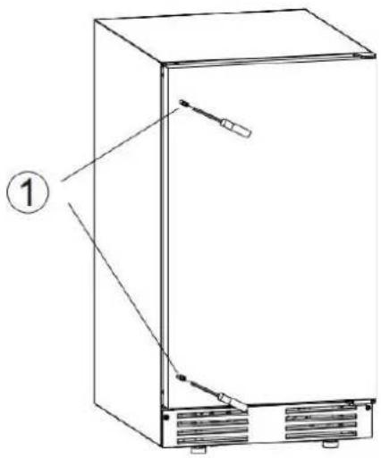
- Install the handle onto the stubs, then use the screwdriver to tighten the screws on the handle.
natural_image
Line drawing of a refrigerator with labeled components and an arrow pointing to the front panel (no text or symbols present)NOTES ABOUT YOUR UNIT
- The operating procedure is completely automatic.
- When the ice bin is full of ice, the machine will automatically stop making ice. It will resume ice-making operation once the ice bin is emptied.
- Using your unit's sensitive probe and accurate timer will optimize the unit's ice-making capabilities.
- The unit has a compressor protection system built in.
TROUBLESHOOTING
Before Calling for Service
If the unit appears to be malfunctioning, read the OPERATION section of this manual first. If the problem persists, check the Troubleshooting Guide on the following pages. Some of the problems mentioned in the Guide can be solved easily without a service call. If you have checked the table below and find that you still need help with your appliance, call our Customer Service facility at 800-932-4267 (Ext. 513) between 9:00 AM and 5:00 PM ET or visit summitappliance.com/support. We will do our best to answer your questions.
Troubleshooting Guide
| Problem | Possible Cause | Solution |
| The machine does not operate. | The icemaker is unplugged. | Plug the icemaker in. |
| The fuse is blown. | Replace fuse. If it happens again, call for service to check for a short circuit in the unit. | |
| The icemaker power button is set to OFF. | Switch the icemaker power button to ON. | |
| The ice storage bin is full of ice. | Remove some ice cubes. Make sure the ice-full probe is free of ice. | |
| The water does not feed in after the machine after it starts. | The water supply tap is turned off | Turn on the water supply tap. |
| The water supply pipe is not properly connected. | Reconnect the water supply pipe. | |
| Machine makes ice, but bin does not fill up with ice. | The condenser may be dirty.The airflow to the icemaker may be obstructed. The ambient temperature and water temperature are high, or unit is near some heat source. | Clean the condenser.Check the installation. Check the installation. |
| Water is leaking out of the unit. | Some water falls to the floor when you open the door to remove ice from the storage bin. | Normal condensation on the door or some water together with ice. Take care when you take out ice. |
| The water supply connection is leaking. | Tighten fitting. See: Connecting the water line. | |
| The drainpipe is higher than the drain outlet. | Lower drainpipe. | |
| Cubes are partially formed or are white on the bottom. | Not enough water in the water trough. | Check if the water supply pressure is below 15 PSIG. |
| Check water supply or filter may be restricted. | ||
| Check for a water leak at the water trough. | ||
| Noise during operation. | The feet are not leveled and locked. | Level and lock the feet. See Leveling the Icemaker. |
| Certain sounds are normal. | See Normal Sounds. | |
| The icemaker stops suddenly while making ice. | The electricity is off. | Reconnect the power supply line. |
| The room temperature is out of the stated range. | Cut off the electricity and leave the icemaker disconnected until the temperature returns to within the stated range. | |
| The ice storage bin is full of ice. | Remove some ice cubes; make sure the ice-full probe is free of ice. | |
| The body of the ice maker is electrified. | The ground line is not in the socket. | Use a socket meeting the grounding requirements. |
| Scaling occurs frequently inside the machine. | The hardness level of the water is too high. | Install a water-softening device in front of the water inlet. |
| Water leaks from the ice storage bin. | The drain hole below the ice storage bin is blocked. | Remove the ice storage bin and clean the drain hole. |
| The drain hose is kinked or improperly placed higher than the floor storage bin. | Check the drain hose to be sure water can be drained out unhindered. |
Appendix
101.DVS.3.3 Qualification of workers
Every working procedure that affects safety means shall only be carried out by competent persons.
Examples for such working procedures are
a) Breaking into the refrigerating circuit
b) Opening of sealed components
c) Opening of ventilated enclosures
101.DVS.4.2 Checks to the area
Prior to beginning work on systems containing FLAMMABLE REFRIGERANTS, safety checks are necessary to ensure that the risk of ignition is minimized. For repair to the REFRIGERATING SYSTEM.
101.DVS.4.3 Work procedure
Work shall be undertaken under a controlled procedure so as to minimize the risk of a flammable gas or vapor being present while the work is being performed.
101.DVS.4.4 General work area
All maintenance staff and others working in the local area shall be instructed on the nature of work being carried out. Work in confined spaces shall be avoided.
101.DVS.4.5 Checking for presence of refrigerant
The area shall be checked with an appropriate refrigerant detector prior to and during work, to ensure the technician is aware of potentially toxic or flammable atmospheres.
Ensure that the leak detection equipment being used is suitable for use with all applicable refrigerants, i.e., non-sparking, adequately sealed, or intrinsically safe.
101.DVS.4.6 Presence of fire extinguisher
If any hot work is to be conducted on the refrigerating equipment or any associated parts, appropriate fire extinguishing equipment shall be available on hand. A dry chemical or CO_2 fire extinguisher should be adjacent to the charging area.
101.DVS.4.7 No ignition sources
No person carrying out work in relation to a REFRIGERATING SYSTEM which involves exposing any pipe work shall use any sources of ignition in such a manner that it may lead to the risk of fire or explosion. All possible ignition sources, including cigarette smoking, should be kept sufficiently far away from the site of installation, repairing, removing and disposal, during which refrigerant can possibly be released to the surrounding space. Prior to work taking place, the area around the equipment shall be surveyed to make sure that there are no flammable hazards or ignition risks. “No Smoking” signs shall be displayed.
101.DVS.4.8 Ventilated area
Ensure that the area is in the open or that it is adequately ventilated before breaking into the system or conducting any hot work. A degree of ventilation shall continue during the period that the work is carried out. The ventilation should safely disperse any released refrigerant and preferably expel it externally into the atmosphere.
101.DVS.4.9 Checks to the refrigerating equipment
Where electrical components are being changed, they shall be fit for the purpose and to the correct specification. At all times, the manufacturer's maintenance and service guidelines shall be followed. If in doubt, consult the manufacturer's technical department for assistance.
The following checks shall be applied to installations using FLAMMABLE REFRIGERANTS:
a) The actual REFRIGERANT CHARGE is in accordance with the room size within which the refrigerant
containing parts are installed
b) The ventilation machinery and outlets are operating adequately and are not obstructed
c) If an indirect refrigerating circuit is being used, the secondary circuit shall be checked for the presence of refrigerant
d) Marking to the equipment continues to be visible and legible. Markings and signs that are illegible shall be corrected
e) Refrigerating pipe or components are installed in a position where they are unlikely to be exposed to any substance which may corrode refrigerant containing components, unless the components are constructed of materials which are inherently resistant to being corroded or are suitably protected against being so corroded
101.DVS.4.10 Checks to electrical devices
Repair and maintenance to electrical components shall include initial safety checks and component inspection procedures. If a fault exists that could compromise safety, then no electrical supply shall be connected to the circuit until it is satisfactorily dealt with. If the fault cannot be corrected immediately but it is necessary to continue operation, an adequate temporary solution shall be used. This shall be reported to the owner of the equipment, so all parties are advised.
Initial safety checks shall include:
a) That capacitors are discharged: this shall be done in a safe manner to avoid possibility of sparking
b) That no live electrical components and wiring are exposed while charging, recovering or purging the system
c) That there is continuity of earth bonding
101.DVS.5 Repairs to sealed components
101.DVS.5.1 During repairs to sealed components, all electrical supplies shall be disconnected from the equipment being worked upon prior to any removal of sealed covers, etc. If it is absolutely necessary to have an electrical supply to equipment during servicing, then a permanently operating form of leak detection shall be located at the most critical point to warn of a potentially hazardous situation.
101.DVS.5.2 Particular attention shall be paid to the following to ensure that by working on electrical components, the casing is not altered in such a way that the level of protection is affected. This shall include damage to cables, excessive number of connections, terminals not made to original specification, damage to seals, incorrect fitting of glands, etc.
Ensure that the apparatus is mounted securely.
Ensure that seals or sealing materials have not degraded to the point that they no longer serve the purpose of preventing the ingress of flammable atmospheres. Replacement parts shall be in accordance with the manufacturer's specifications.
101.DVS.6 Repair to intrinsically safe components
Do not apply any permanent inductive or capacitance loads to the circuit without ensuring that this will not exceed the permissible voltage and current permitted for the equipment in use.
Intrinsically safe components are the only types that can be worked on while live in the presence of a flammable atmosphere. The test apparatus shall be at the correct rating.
Replace components only with parts specified by the manufacturer. Other parts can result in the ignition of refrigerant in the atmosphere from a leak.
NOTE: The use of silicon sealant can inhibit the effectiveness of some types of leak detection equipment.
Intrinsically safe components do not have to be isolated prior to working on them.
101.DVS.7 Cabling
Check that cabling will not be subject to wear, corrosion, excessive pressure, vibration, sharp edges, or any other adverse environmental effects. The check shall also take into account the effects of aging or continual vibration from sources such as compressors or fans.
101.DVS.8 Detection of flammable refrigerants
Under no circumstances shall potentially sources of ignition be used in the searching for or detection of refrigerant leaks. A halide torch (or any other detector using a naked flame) shall not be used.
The following leak detection methods are deemed acceptable for all refrigerant systems.
Electronic leak detectors may be used to detect refrigerant leaks but, in the case of FLAMMABLE REFRIGERANTS, the sensitivity might not be adequate, or might need recalibration. (Detection equipment shall be calibrated in a refrigerant-free area.) Ensure that the detector is not a potential source of ignition and is suitable for the refrigerant used.
Leak detection equipment shall be set at a percentage of the LFL of the refrigerant and shall be calibrated to the refrigerant employed, and the appropriate percentage of gas (25 % maximum) is confirmed.
Leak detection fluids are also suitable for use with most refrigerants but the use of detergents containing chlorine shall be avoided as the chlorine can react with the refrigerant and corrode the copper pipe-work.
NOTE: Examples of leak detection fluids are
- bubble method
– fluorescent method agents
If a leak is suspected, all naked flames shall be removed/extinguished.
If a leakage of refrigerant is found which requires brazing, all of the refrigerant shall be recovered from the system, or isolated (by means of shut off valves) in a part of the system remote from the leak. Removal of refrigerant shall be according to Clause 101.DVS.9.
101.DVS.9 Removal and evacuation
When breaking into the refrigerant circuit to make repairs – or for any other purpose – conventional procedures shall be used. However, for flammable refrigerants it is important that best practice be followed, since flammability is a consideration. The following procedure shall be adhered to:
a) Safely remove refrigerant following local and national regulations
b) Purge the circuit with inert gas
c) Evacuate (optional for A2L)
d) Purge with inert gas (optional for A2L)
e) Open the circuit by cutting or brazing
The refrigerant charge shall be recovered into the correct recovery cylinders if venting is not allowed by local and national codes. For appliances containing flammable refrigerants, the system shall be purged with oxygen-free nitrogen to render the appliance safe for flammable refrigerants. This process might need to be repeated several times.
Compressed air or oxygen shall not be used for purging refrigerant systems.
For appliances containing flammable refrigerants, refrigerants purging shall be achieved by breaking the vacuum in the system with oxygen-free nitrogen and continuing to fill until the working pressure is achieved, then venting to atmosphere, and finally pulling down to a vacuum (optional for A2L). This process shall be repeated until no refrigerant is within the system (optional for A2L). When the final oxygen-free nitrogen charge is used, the system
shall be vented down to atmospheric pressure to enable work to take place.
Ensure that the outlet for the vacuum pump is not close to any potential ignition sources and that ventilation is available.
101.DVS.10 Charging procedures
In addition to conventional charging procedures, the following requirements shall be followed.
a) Ensure that contamination of different refrigerants does not occur when using charging equipment. Hoses or lines shall be as short as possible to minimize the amount of refrigerant contained in them.
b) Cylinders shall be kept in an appropriate position according to the instructions.
c) Ensure that the REFRIGERATING SYSTEM is earthed prior to charging the system with refrigerant.
d) Label the system when charging is complete (if not already).
e) Extreme care shall be taken not to overfill the REFRIGERATING SYSTEM. Prior to recharging the system, it shall be pressure-tested with the appropriate purging gas. The system shall be leak-tested on completion of charging but prior to commissioning. A follow up leak test shall be carried out prior to leaving the site.
101.DVS.11 Decommissioning
Before carrying out this procedure, it is essential that the technician is completely familiar with the equipment and all its detail. It is recommended good practice that all refrigerants are recovered safely. Prior to the task being carried out, an oil and refrigerant sample shall be taken in case analysis is required prior to re-use of recovered refrigerant. It is essential that electrical power is available before the task is commenced.
a) Become familiar with the equipment and its operation.
b) Isolate the system electrically.
c) Before attempting the procedure, ensure that:
i) mechanical handling equipment is available, if required, for handling refrigerant cylinders;
ii) all personal protective equipment is available and being used correctly;
iii) the recovery process is supervised at all times by a competent person;
iv) recovery equipment and cylinders conform to the appropriate standards.
d) Pump down refrigerant system, if possible.
e) If a vacuum is not possible, make a manifold so that refrigerant can be removed from various parts of the system.
f) Make sure that cylinder is situated on the scales before recovery takes place.
g) Start the recovery machine and operate in accordance with instructions.
h) Do not overfill cylinders (no more than 80 % volume liquid charge).
i) Do not exceed the maximum working pressure of the cylinder, even temporarily.
j) When the cylinders have been filled correctly and the process completed, make sure that the cylinders and the equipment are removed from site promptly and all isolation valves on the equipment are closed off.
k) Recovered refrigerant shall not be charged into another REFRIGERATING SYSTEM unless it has been cleaned and checked.
101.DVS.12 Labelling
Equipment shall be labelled stating that it has been de-commissioned and emptied of refrigerant. The label shall be dated and signed. For appliances containing FLAMMABLE REFRIGERANTS, ensure that there are labels on the equipment stating the equipment contains FLAMMABLE REFRIGERANT.
101.DVS.13 Recovery
When removing refrigerant from a system, either for servicing or decommissioning, it is recommended good practice that all refrigerants are removed safely.
When transferring refrigerant into cylinders, ensure that only appropriate refrigerant recovery cylinders are employed. Ensure that the correct number of cylinders for holding the total system charge is available. All cylinders to be used are designated for the recovered refrigerant and labelled for that refrigerant (i.e., special cylinders for the recovery of refrigerant). Cylinders shall be complete with pressure-relief valve and associated shut-off valves in good working order. Empty recovery cylinders are evacuated and, if possible, cooled before recovery occurs.
The recovery equipment shall be in good working order with a set of instructions concerning the equipment that is at hand and shall be suitable for the recovery of all appropriate refrigerants including, when applicable, FLAMMABLE REFRIGERANTS. In addition, a set of calibrated weighing scales shall be available and in
good working order. Hoses shall be complete with leak-free disconnect couplings and in good condition. Before using the recovery machine, check that it is in satisfactory working order, has been properly maintained and that any associated electrical components are sealed to prevent ignition in the event of a refrigerant release. Consult manufacturer if in doubt.
The recovered refrigerant shall be returned to the refrigerant supplier in the correct recovery cylinder, and the relevant waste transfer note arranged. Do not mix refrigerants in recovery units and especially not in cylinders. If compressors or compressor oils are to be removed, ensure that they have been evacuated to an acceptable level to make certain that FLAMMABLE REFRIGERANT does not remain within the lubricant. The evacuation process shall be carried out prior to returning the compressor to the suppliers. Only electric heating to the compressor body shall be employed to accelerate this process. When oil is drained from a system, it shall be carried out safely.
NOTES
LIMITED WARRANTY
ONE-YEAR LIMITED WARRANTY
Within the 48 contiguous United States, for one year from the date of purchase, when this appliance is operated and maintained according to instructions attached to or furnished with the product, warrantor will pay for factory- specified parts and repair labor to correct defects in materials or workmanship. Service must be provided by a designated service company. Outside the 48 states, all parts are warranted for one year from manufacturing defects. Plastic parts, shelves and cabinets are warranted to be manufactured to commercially acceptable standards and are not covered from damage during handling or breakage.
5-YEARS COMPRESSOR WARRANTY
- The compressor is covered for 5 years.
2 Replacement does not include labor.
ITEMS WARRANTOR WILL NOT PAY FOR:
- Service calls to correct the installation of your appliance, to instruct you how to use your appliance, to replace or repair fuses or to correct wiring or plumbing.
2 Service calls to repair or replace appliance light bulbs or broken shelves. Consumable parts (such as filters) are excluded from warranty coverage. - Damage resulting from accident, alteration, misuse, abuse, fire, flood, acts of God, improper installation, installation not in accordance with electrical or plumbing codes, or use of products not approved by warrantor.
- Replacement parts or repair labor costs for units operated outside the United States.
- Repairs to parts or systems resulting from unauthorized modifications made to the appliance.
- The removal and reinstallation of your appliance if it is installed in an inaccessible location or is not installed in accordance with published installation instructions.
DISCLAIMER OF IMPLIED WARRANTIES; LIMITATION OF REMEDIES
CUSTOMER'S SOLE AND EXCLUSIVE REMEDY UNDER THIS LIMITED WARRANTY SHALL BE PRODUCT REPAIR AS PROVIDED HEREIN. IMPLIED WARRANTIES, INCLUDING WARRANTIES OF MERCHANTABILITY OR FITNESS FOR A PARTICULAR PURPOSE, ARE LIMITED TO ONE YEAR. WARRANTOR SHALL NOT BE LIABLE FOR INCIDENTAL OR CONSEQUENTIAL DAMAGES. SOME STATES DO NOT ALLOW THE EXCLUSION OR LIMITATION OF INCIDENTAL OR CONSEQUENTIAL DAMAGES, OR LIMITATIONS ON THE DURATION OF IMPLIED WARRANTIES OF MERCHANTABILITY OR FITNESS, SO THESE EXCLUSIONS OR LIMITATIONS MAY NOT APPLY TO YOU. THIS WARRANTY GIVES YOU SPECIFIC LEGAL RIGHTS AND YOU MAY ALSO HAVE OTHER RIGHTS, WHICH VARY FROM STATE TO STATE.

WARNING: This product can expose you to chemicals including Nickel (Metallic) which is known to the State of
California to cause cancer. For more information go to www.P65Warnings.ca.gov
Note: Nickel is a component in all stainless steel and some other metal components.
Felix Storch, Inc.
An ISO 9001:2015 registered company
770 Garrison Ave
Bronx, New York 10474
www.summitappliance.com

For parts and accessory ordering,
troubleshooting and helpful hints, visit:
www.summitappliance.com/support
natural_image
Line drawing of a rectangular refrigerator with front panel and side door (no text or symbols)MODÈLE
BIM182ADA/ BIM182 BIM182OS/ BIM182OSADA/ LBIM18 DBBIM1863ADA/ DBBIMOS1864ADA
natural_image
Warning symbol with exclamation mark inside a triangle (no text or numbers)natural_image
Two black electrical hazard symbols: a curved line and a lightning bolt symbol (no text or labels)natural_image
Line drawing of a refrigerator with labeled 'Up' and 'Down' directional arrows (no text or symbols on the device itself)natural_image
Isometric technical drawing of a mechanical assembly with internal components (no text or symbols)natural_image
Isometric line drawing of a mechanical component with internal grid structure (no text or symbols)natural_image
Isometric technical drawing of a mechanical component with no visible text or symbolsL e bac est plein
natural_image
Close-up of a mechanical or electronic component with blue and white components, no visible text or symbols
natural_image
Close-up of a mechanical or electrical component with blue and white components, no visible text or symbolsnatural_image
Interior view of an electronic device showing exposed circuit board and wiring (no visible text or symbols)NOTE :
natural_image
Close-up of a white electronic device with a red arrow pointing to a component (no visible text or symbols)natural_image
Technical line drawing of an open refrigerator with internal compartments and a close-up inset showing mechanical components (no text or symbols)natural_image
Line drawing of a refrigerator with doors open and side arm, showing internal compartments and ventilation slots (no text or labels)natural_image
Isometric technical drawing of a rectangular plate with circular holes and a vertical rod inserted into it (no text or symbols)natural_image
Isometric view of a rectangular tray with evenly spaced circular holes (no text or symbols)natural_image
Line drawing of a refrigerator interior showing front and rear panels with no text or symbolsnatural_image
Technical line drawing of a rectangular electronic device with internal components and wiring (no text or symbols)natural_image
Line drawing of an open refrigerator with ventilation slots and doors (no text or symbols)INSTALLATION DU POIGNÉE.
natural_image
Line drawing of a refrigerator with labeled components (no text or symbols present)natural_image
Line drawing of a refrigerator with labeled components and an arrow pointing to the interior panel (no text or symbols present)REMARQUES SUR VOTRE UNITÉ
Equipment shall be labelled stating that it has been de-commissioned and emptied of refrigerant. The label shall be dated and signed. For appliances containing FLAMMABLE REFRIGERANTS, ensure that there are labels on the equipment stating the equipment contains FLAMMABLE REFRIGERANT.
GARANTIE LIMITÉE D'UN AN


- Automatic Undercounter Icemaker
- MODEL
- User's Manual
- TABLE OF CONTENTS
- ICEMAKER SAFETY
- IMPORTANT SAFETY INSTRUCTIONS
- SAVE THESE INSTRUCTIONS
- IMPORTANT SAFEGUARDS
- ! DANGER !
- WARNING
- ENVIRONMENT
- Electrical Connection
- Extension Cord
- UV Light
- The Fire Symbol
- Climate class
- INTRODUCTION
- PARTS LOCATIONS
- ICEMAKER INSTALLATION
- Unpacking
- Excessive Weight Hazard
- Cleaning before use
- Location Requirements
- Electrical Requirements
- Electrical Shock Hazard
- Recommended grounding method
- Leveling the Icemaker
- Water Supply
- IMPORTANT:
- Tools required:
- Connecting the water line:
- Drain
- Connecting the drain line:
- NOTE: If there is a drain line near the icemaker, the best choice is to drain water to the drain line through the drain water hose provided with icemaker.
- Installation Types
- Free-standing installation:
- Enclosed Installation:
- Built-in installation:
- OPERATION
- Final Check List Before Initial Use
- Using Your Icemaker
- How The Machine Makes Ice
- How The Machine Uses the Water
- How The Drain System Operates When Water Is Pumped Out
- NOTE:
- WARNING!
- Icemaking Diagram
- Sounds Your Icemaker Makes
- Preparing the Icemaker for Vacation
- CLEANING AND MAINTENANCE
- Parts to Keep Clean
- Cleaning the exterior
- Cleaning the Interior
- Cleaning the Condenser
- Cleaning the Water Distribution Tube
- Cleaning the Ice-making System
- Control Panel:
- Description of LEDs and buttons:
- Ice size button:
- UV button:
- Timer button:
- Alarm and Error codes:
- Manual de-icing
- REVERSING THE DOOR SWING
- INSTALLATING THE HANDLE.
- NOTES ABOUT YOUR UNIT
- TROUBLESHOOTING
- Before Calling for Service
- Appendix
- 101.DVS.3.3 Qualification of workers
- 101.DVS.4.2 Checks to the area
- 101.DVS.4.3 Work procedure
- 101.DVS.4.4 General work area
- 101.DVS.4.5 Checking for presence of refrigerant
- 101.DVS.4.6 Presence of fire extinguisher
- 101.DVS.4.7 No ignition sources
- 101.DVS.4.8 Ventilated area
- 101.DVS.4.9 Checks to the refrigerating equipment
- 101.DVS.4.10 Checks to electrical devices
- 101.DVS.5 Repairs to sealed components
- 101.DVS.6 Repair to intrinsically safe components
- 101.DVS.7 Cabling
- 101.DVS.8 Detection of flammable refrigerants
- 101.DVS.9 Removal and evacuation
- 101.DVS.10 Charging procedures
- 101.DVS.11 Decommissioning
- 101.DVS.12 Labelling
- 101.DVS.13 Recovery
- NOTES
- LIMITED WARRANTY
- ONE-YEAR LIMITED WARRANTY
- 5-YEARS COMPRESSOR WARRANTY
- ITEMS WARRANTOR WILL NOT PAY FOR:
- DISCLAIMER OF IMPLIED WARRANTIES; LIMITATION OF REMEDIES
- MODÈLE
- NOTE :
- INSTALLATION DU POIGNÉE.
- REMARQUES SUR VOTRE UNITÉ
- GARANTIE LIMITÉE D'UN AN
Brand : Summit
Model : BIM182OS
Category : Ice Maker