
AMAP151CW - Air Conditioning AMANA - Free user manual and instructions
Find the device manual for free AMAP151CW AMANA in PDF.

| Product Type | Individual window air conditioner |
| Brand | Amana |
| Model | AMAP151CW |
| Cooling Capacity | 15 000 BTU |
| Power Supply | 115 V, 12 A, 60 Hz |
| Electrical Protection | 15 A time-delay fuse or circuit breaker |
| Required Outlet | 3-prong grounded outlet |
| Dimensions (window opening) | Width: 71.1 to 104.2 cm; free height: 48.3 cm |
| Operating Modes | Cooling, Dehumidification, Fan, Eco, Sleep |
| Fan Speeds | Low, Medium, High, Auto |
| Timer | Delayed stop and start from 0.5 h to 24 h |
| Remote Control | Yes, with AAA batteries (2 included) |
| Display | LED screen with mode and temperature indicators |
| Air Filter | Washable, with cleaning reminder every 500 hours |
| Maintenance | Clean filter every 2 weeks; clean front panel with a soft cloth |
| Safety | Power cord with RESET/TEST; do not use an extension cord |
| Installation | In a double-hung window; requires 2 people |
| Spare Parts | Air filter, remote control, foam seals, brackets |
| Warranty | 1 year limited (parts and labor) |
| Customer Service (Canada) | 1-800-207-1156 |
Frequently Asked Questions - AMAP151CW AMANA
User questions about AMAP151CW AMANA
0 question about this device. Answer the ones you know or ask your own.
Ask a new question about this device
Download the instructions for your Air Conditioning in PDF format for free! Find your manual AMAP151CW - AMANA and take your electronic device back in hand. On this page are published all the documents necessary for the use of your device. AMAP151CW by AMANA.
USER MANUAL AMAP151CW AMANA
For questions about features, operation/performance, parts, or service, call: 1-800-207-1156. In Canada, for assistance, installation, or service, call: 1-800-207-1156.
Table of Contents
AIR CONDITIONER SAFETY 2
INSTALLATION REQUIREMENTS....3
INSTALLATION INSTRUCTIONS—6,000-12,000 BTU MODELS....7
WINDOW INSTALLATION INSTRUCTIONS—15,000-24,000 BTU MODELS....10
WALL INSTALLATION INSTRUCTIONS—15,000-24,000 BTU MODELS....14
USING YOUR AIR CONDITIONER....16
AIR CONDITIONER CARE....19
TROUBLESHOOTING 20
ASSISTANCE OR SERVICE....21
XLS PRODUCTS WARRANTY FOR AMANA® AIR CONDITIONERS....22
Climatiseur
ASSISTANCE OU SERVICE....42
GARANTIE DE XLS PRODUCTS POUR LES CLIMATISEURS AMANA®......43
AMAP061BW AMAP151BW AMAP081BW AMAP182BW AMAP101BW AMAP222BW AMAP121BW AMAP242BW
®/TM ©2018 Amana. All rights reserved. Manufactured under license by XLS Products, Pennsylvania.
Your safety and the safety of others are very important.
We have provided many important safety messages in this manual and on your appliance. Always read and obey all safety messages.

This is the safety alert symbol.
This symbol alerts you to potential hazards that can kill or hurt you and others.
All safety messages will follow the safety alert symbol and either the word "DANGER" or "WARNING." These words mean:
! DANGER
You can be killed or seriously injured if you don't immediately follow instructions.
WARNING
You can be killed or seriously injured if you don't follow instructions.
All safety messages will tell you what the potential hazard is, tell you how to reduce the chance of injury, and tell you what can happen if the instructions are not followed.
IMPORTANT SAFETY INSTRUCTIONS
WARNING: To reduce the risk of fire, electrical shock or injury when using your air conditioner, follow these basic precautions:
■ Plug into a grounded 3 prong outlet.
■ Do not remove ground prong.
■ Do not use an adapter.
This appliance is not intended for use by persons (including children) with reduced physical, sensory, or mental capabilities, or lack experience and knowledge, unless they have been given supervision or instruction concerning the use of appliance by a person responsible for their safety.
■ Do not use an extension cord.
■ Unplug air conditioner before servicing.
■ Use two or more people to move and install air conditioner.
■ Do not drink water collected in the water bucket.
■ Children should be supervised to ensure that they do not play with the appliance.
SAVE THESE INSTRUCTIONS
INSTALLATION REQUIREMENTS
Electrical Requirements—All Models
WARNING

Electrical Shock Hazard
Plug into a grounded 3 prong outlet.
Do not remove ground prong.
Do not use an adapter.
Do not use an extension cord.
Failure to follow these instructions can result in death, fire, or electrical shock.
The electrical ratings for your air conditioner are listed on the model and serial number label. The model and serial number label is located on the right-hand side of the air conditioner cabinet.
Specific electrical requirements are listed in the “Electrical Requirements” sections. Follow the requirements for the type of plug shown in these sections.
Electrical Requirements—115 V Models
Model BTUs - 6,000; 8,000; 10,000; 12,000; 15,000
All models -
■115 volts - (103.5 min. - 126.5 max.)
If there is a "Single Circuit Only" label on the unit, use on a dedicated single-outlet circuit only. If a dedicated single-outlet circuit is not available, then it is the customer's responsibility to have a single-outlet circuit installed by a qualified electrician.
■If there is no “Single Circuit Only” label on the unit, the unit may be used on any branch circuit of correct voltage and adequate current protection rating.
6,000-8,000 BTU models -
■0-8 amps
■10-amp time-delay fuse or circuit breaker
10,000-15,000 BTU models -
■0-12 amps
■15-amp time-delay fuse or circuit breaker
Electrical Requirements—230 V Models
Model BTUs - 18,000; 22,000; 24,000
■230 volts (208 min. - 240 max.)
■6.6-11 amps
■15-amp time-delay fuse or circuit breaker
■If there is a “Single Circuit Only” label on the unit, use on a dedicated single-outlet circuit only.
If a dedicated single-outlet circuit is not available, then it is the customer's responsibility to have a single-outlet circuit installed by a qualified electrician.
■If there is no "Single Circuit Only" label on the unit, the unit may be used on any branch circuit of correct voltage and adequate current protection rating.
Recommended Grounding Method
This air conditioner must be grounded. This air conditioner is equipped with a power supply cord having a grounded 3 prong plug. To minimize possible shock hazard, the cord must be plugged into a mating, grounded 3 prong outlet, grounded in accordance with all local codes and ordinances. If a mating outlet is not available, it is the customer's responsibility to have a properly grounded 3 prong outlet installed by a qualified electrical installer. It is the customer's responsibility:
■To contact a qualified electrical installer.
■To assure that the electrical installation is adequate and in conformance with National Electrical Code, ANSI/NFPA 70—latest edition, and all local codes and ordinances.
Copies of the standards listed may be obtained from:
National Fire Protection Association
1 Batterymarch Park
Quincy, MA 02269
Power Supply Cord—All Models
WARNING

Electrical Shock Hazard
Plug into a grounded 3 prong outlet.
Do not remove ground prong.
Do not use an adapter.
Do not use an extension cord.
Failure to follow these instructions can result in death, fire, or electrical shock.
NOTE: Your air conditioner's power supply cord may differ from those shown.
This air conditioner is equipped with a power supply cord required by UL. This power supply cord contains state-of-the-art electronics that sense leakage current. If the cord is crushed, the electronics detect leakage current and power will be disconnected in a fraction of a second.
To test your power supply cord:
- Plug power supply cord into a grounded 3 prong outlet.
- Press RESET (on some models, a green light will turn on).
- Press TEST (listen for click; Reset button will trip, and on some devices, a green light will turn off).
- Press and release RESET (listen for click; Reset button will latch, and on some devices, a green light will turn on). The power supply cord is ready for operation.
NOTES:
■The Reset button must be pushed in for proper operation.
■The power supply cord must be replaced if it fails to trip when the test button is pressed or fails to reset.
■Do not use the power supply cord as an off/on switch. The power supply cord is designed as a protective device.
■A damaged power supply cord must be replaced with a new power supply cord obtained from the product manufacturer and must not be repaired.
■The power supply cord contains no user-serviceable parts. Opening the tamper-resistant case voids all warranty and performance claims.
Tools Required—All Models
Gather the required tools and parts before starting installation. Read and follow the instructions provided with any tools listed here.
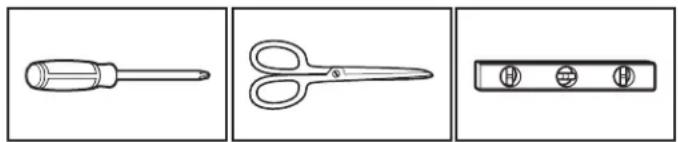
Phillips screwdriver
Scissors
Level
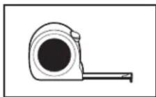
Tape measure
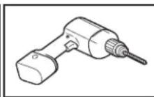
Cordless drill and 1/8" bit

Pencil
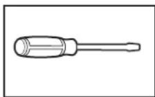
Flathead screwdriver Adjustable wrench or pliers
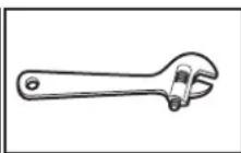
Adjustable wrench or pliers
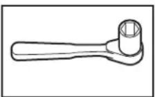
Socket wrenches
Parts Supplied: 6,000-12,000 BTU models
Check that all parts are included in parts package.
NOTE: Not all parts are included with all models.
A. Foam seal with adhesive strip
B. Foam seal without adhesive strip
C. Sash lock x1
D. Lock frame x2
E. 1/2" screws x3
F. 3/4" screws x4
G. Side curtains x2
H. 3/8" screws x4
I. Top channel (appearance may vary)
Other: AAA batteries x2
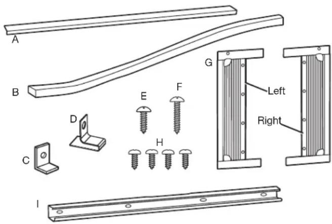
Parts Supplied—15,000-24,000 BTU Models
Check that all parts are included in parts package.
NOTE: Not all parts are included with all models.
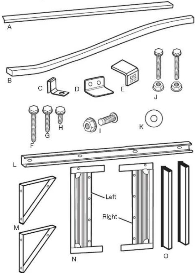
A. Foam seal with adhesive strip
B. Foam seal without adhesive strip
C. Side curtain bracket x2
D. Safety lock
E. Sill angle bracket x2
F. 1/2" hex-head screw x2
G. 5/8" hex-head screw x4
H. 5/16" hex-head screw x10
I. 5/8" flathead bolt with locknut x2
J. 1/2" flathead bolt with locknut x4
K. Gasket x2
L. Top channel (appearance may vary)
M. Window support bracket x2
N. Side curtains x2
O. Side retainers x2
Other: AAA batteries x2
Location Requirements—Window Installation
IMPORTANT: Observe all governing codes and ordinances.
Check the location where the air conditioner will be installed. Make sure you have everything necessary for correct installation.
The location should provide:
■Grounded electrical outlet within 6 ft (183 cm) of where the power cord exits the air conditioner. Do not use an extension cord.
■Free movement of air in room to be cooled.
■A large enough opening for the air conditioner. Installation parts are supplied for double-hung windows.
NOTE: The air conditioner can be installed without the side panels to fit in a narrow window opening.
■Adequate wall support for weight of air conditioner.
■Firm wood, masonry, or metal to secure to supporting parts.
NOTE: Cabinet louvers must not be obstructed. Air must be able to pass freely through the cabinet louvers.
Window Opening Measurements
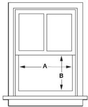
| Model BTUs Width (A) Minimum | Opening (B) | |
| 6,000-8,000 | 23"-36"(58.4 cm-91.4 cm) | 14 12 "(36.8 cm) |
| 10,000-12,000 | 26"-36"(66 cm-91.4 cm) | 16"(40.6 cm) |
| 15,000-18,000 28" | -41"(71.1 cm-104.2 cm) | 19"(48.3 cm) |
| 22,000-24,000 | 30"-41"(76.2 cm-104.2 cm) | 19 12 "(49.5 cm) |
Prepare Window Opening
1. Measure and mark center line
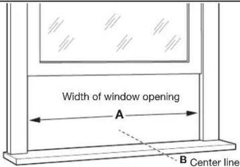
Measure the width of the window opening (A). Mark the center line (B) of the window on the inside windowsill.
2. Attach upper foam seal
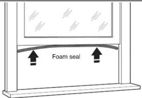
Attach the foam seal with adhesive strip to the bottom of the window sash.
Preparing Window with Storm Window or Other Obstruction
Follow the steps in "Prepare Window Opening".
If possible, remove the storm window frame or other obstruction.
If the storm window frame or obstruction CANNOT be removed, a wood spacer will be required to ensure that the air conditioner slopes to the outside. This will allow condensation and rainwater to drain away. Make sure that drain holes or slots are not caulked or painted shut.
1. Measure size of spacer needed
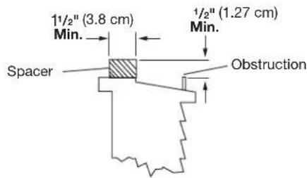
Using a level and measuring tape, determine thickness of wood spacer needed to allow the air conditioner to slope downward slightly to the outdoors. The block should provide at least 1/2" (1.27 cm) of height above the obstruction.
2. Place block on windowsill
A. Piece of wood
B. Windowsill
C Indoors
D. Outdoors
E. Storm window frame or other obstruction
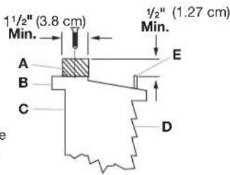
Place wood spacer on windowsill. Spacer should be at least the full width of the air conditioner cabinet.
INSTALLATION INSTRUCTIONS—6,000-12,000 BTU MODELS
Prepare Air Conditioner for Installation
WARNING
Excessive Weight Hazard
Use two or more people to move and install air conditioner.
Failure to do so can result in back or other injury.
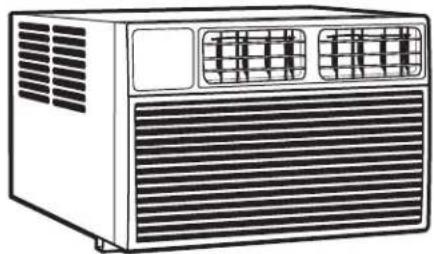
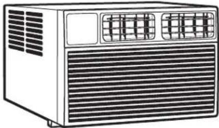
1. Unpack the Air Conditioner
natural_image
Line drawing of a portable air conditioner unit with ventilation grilles and ventilation grilles (no text or symbols)Remove Packaging Materials:
■Handle the air conditioner gently while unpacking the unit.
■Place the air conditioner on a hard, flat surface.
■Remove tape and glue residue from surfaces before turning on the air conditioner. Rub a small amount of liquid dish soap over the adhesive with your fingers. Wipe with a damp cloth and dry.
■Do not use sharp instruments, rubbing alcohol, flammable fluids, or abrasive cleaners to remove tape or glue. These products can damage the surface of your air conditioner.
■Remove any packaging materials inserted into the side louvers.
■Dispose of/recycle packaging materials in an appropriate way.
2. Install top channel
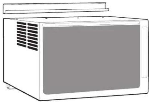
natural_image
Line drawing of a microwave oven with ventilation grilles and lid (no text or symbols)Place the top channel on the top of the air conditioner, lining up the holes in the top channel with the holes in the top of the air conditioner.
3. Attach screws
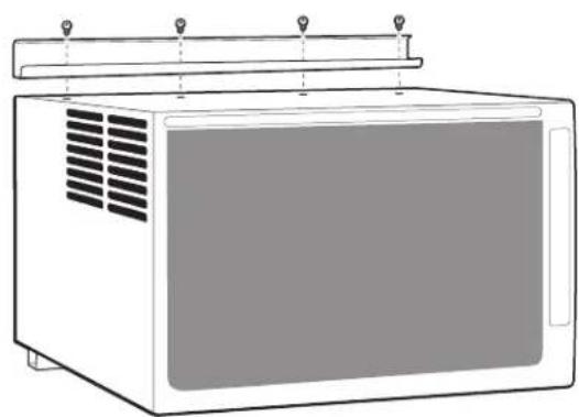
natural_image
Line drawing of a microwave oven with ventilation grilles and top-mounted lid (no text or symbols)Using four 3/8" screws, attach the top channel to the air conditioner.
Install Side Curtains
NOTE: Attach curtains to the air conditioner before placing the air conditioner in window.
1. Install side curtain
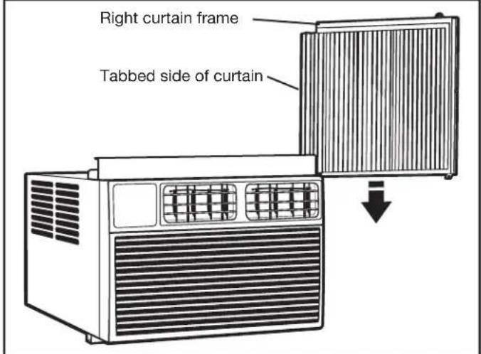
Holding the center of the right-hand side panel in one hand, pull the curtain open. Place the tabbed side of the side curtain in the track on the right-hand side of the air conditioner cabinet.
Slide the side curtain down the track, making sure to leave enough space to slip the top and bottom of the frame into the channels on the cabinet.
2. Insert curtain frame into channels
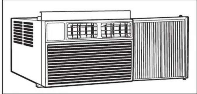
natural_image
Line drawing of a portable air conditioner unit with ventilation grilles and front panel (no text or symbols)Slide the side curtain frame into the top channel and bottom channels of the air conditioner. Make slight adjustments until the panel sits securely inside the channels.
Repeat steps 1 and 2 for other side curtain and frame.
Install Air Conditioner in Window
WARNING
Excessive Weight Hazard
Use two or more people to move and install air conditioner.
Failure to do so can result in back or other injury.
IMPORTANT:
■Be sure your air conditioner does not fall out of the opening during installation or removal.
■The place where the power cord exits the air conditioner should be no more than 6 ft (183 cm) from a grounded outlet
■To maximize cooling efficiency and air circulation, do not block the air intake or discharge louvers in the front panel.
■To reduce cycling on and off of the compressor and reduce the risk of freezing up or damage to the unit, do not block the louvers on the outside of the air conditioner.
1. Position air conditioner in window
A. Air conditioner
C Windowsill
B. Bottom channel
D. Outside
Using two or more people, place the air conditioner into the window opening so the bottom of the air conditioner frame is against the window sill. Tilt the back of the unit slightly downward to allow accumulated rain water to drain out.
2. Lower window sash into place
A. Side curtain against window channel
B. Window sash behind top channel
C. Bottom channel behind window sill
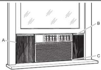
Lower the window sash behind the top channel to hold the air conditioner in place.
NOTE: Your model may differ from the one shown.
Extend side curtains out until they fit into the window channels.
Attach the right angle sash lock with a 3/4" screw.
Slide a side bracket over the bottom corner of each side curtain frame.
Using a 1/8" drill bit, drill a starter hole through the hole in the side curtain bracket and into the windowsill.
Insert the foam seal without adhesive strip between the top of the lower window sash and the glass of the upper window.
Remove any remaining clear plastic film from the control panel and plastic front panel.
Secure each bracket to the windowsill with a 3/4" screw.
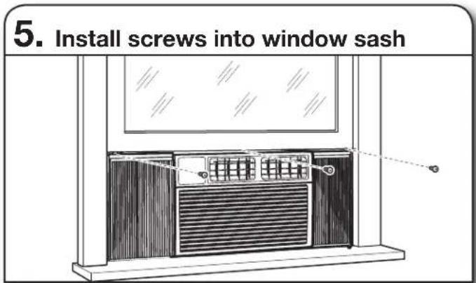
Use a 1/8" drill bit to drill a starter hole through the holes in the top rail and the top corners of the side curtains into the window sash.
Secure with three 1/2" screws through the holes in the top rail and side curtain and into the window sash.
WINDOW INSTALLATION INSTRUCTIONS—15,000-24,000 BTU MODELS
Prepare Air Conditioner for Installation
WARNING
Excessive Weight Hazard
Use two or more people to move and install air conditioner.
Failure to do so can result in back or other injury.
1. Unpack the Air Conditioner
natural_image
Line drawing of a portable air conditioner unit with ventilation grilles and ventilation grilles (no text or symbols)Remove Packaging Materials:
■Handle the air conditioner gently while unpacking the unit.
■Place the air conditioner on a hard, flat surface.
■Remove tape and glue residue from surfaces before turning on the air conditioner. Rub a small amount of liquid dish soap over the adhesive with your fingers. Wipe with a damp cloth and dry.
■Do not use sharp instruments, rubbing alcohol, flammable fluids, or abrasive cleaners to remove tape or glue. These products can damage the surface of your air conditioner.
■Remove any packaging materials inserted into the side louvers.
■Dispose of/recycle packaging materials in an appropriate way.
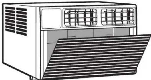
2. Remove filter and front panel
natural_image
Line drawing of a portable air conditioner unit with ventilation grilles and ventilation grilles (no text or symbols)Pull down the front panel and remove the filter. Lift the front panel upwards and remove from the air conditioner. Place to the side.
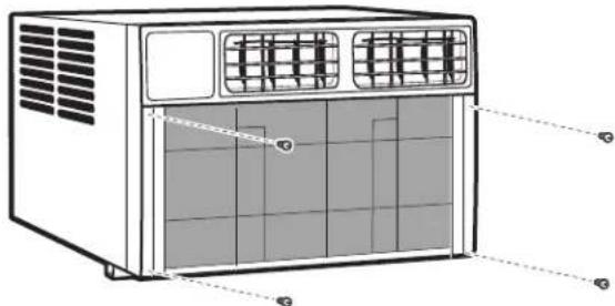
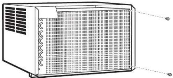
3. Remove faceplate screws
natural_image
Illustration of a portable air conditioner unit with labeled panel edges (no text or symbols present)Remove the four faceplate screws.
NOTE: The faceplate screws must be reinstalled before mounting the air conditioner.
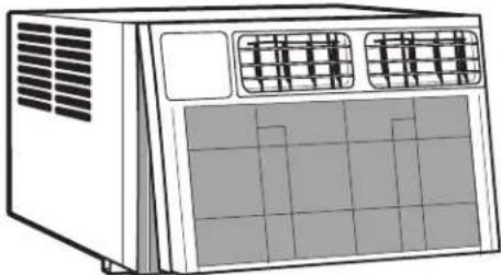
4. Remove faceplate
natural_image
Line drawing of a portable air conditioner unit with ventilation grilles and control panel (no text or symbols)Gently remove the faceplate from the air conditioner cabinet.
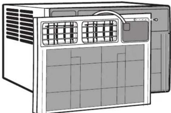
5. Remove control panel screw
natural_image
Illustration of a server rack unit with ventilation grilles and ventilation ducts (no text or symbols)Remove the control panel screw from the front panel.
- Remove right-side screws
natural_image
Technical line drawing of a rectangular industrial fan or enclosure with ventilation grilles and heat sinks (no text or symbols)Remove the screws from the right side of the cabinet.
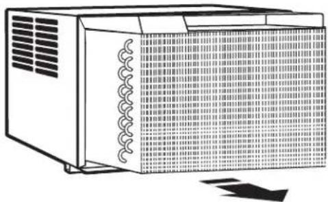
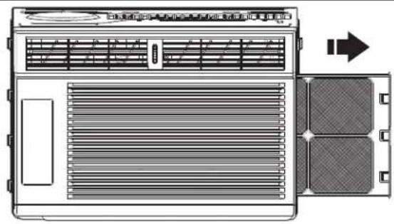
- Remove chassis
natural_image
Line drawing of a microwave oven with ventilation grilles and a coiled cord (no text or symbols)IMPORTANT: To avoid damage, do not pull or lift near the top of the unit.
Hold the cabinet while pulling on the base handle to carefully remove the unit.
Install Top Channel and Side Bracket
1. Attach foam gasket
Place air conditioner on a hard, flat surface. Attach the foam gasket to the top angle channel.
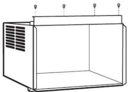
- Install top angle channel
natural_image
Line drawing of a rectangular industrial enclosure with ventilation grilles and three hanging lights (no text or symbols)Attach the top angle channel to the cabinet with four 5/16" hex-head screws.
- Slide in side panels
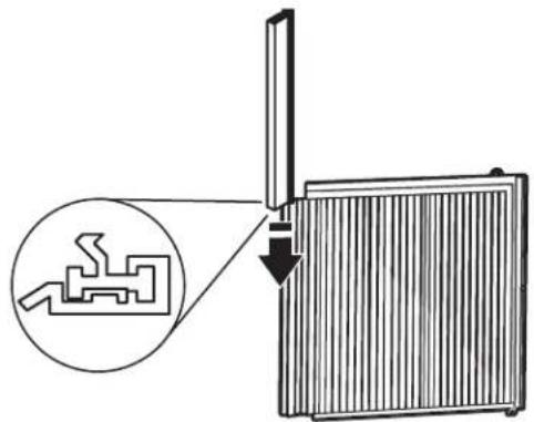
Slide the "I" section of the window panel into the side bracket f the cabinet. Do this for both sides.
- Attach side panels
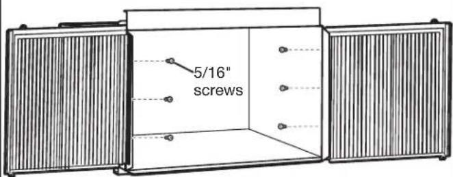
Insert the top and bottom legs of the window filler panel frame into the top angle channel and bottom channel. Secure with 5/16" screws. Repeat on the other side and install side retainer into cabinet.
Install Air Conditioner in Window
WARNING
Excessive Weight Hazard
Use two or more people to move and install air conditioner.
Failure to do so can result in back or other injury.
IMPORTANT:
■Be sure your air conditioner does not fall out of the opening during installation or removal.
■The place where the power cord exits the air conditioner should be no more than 6 ft (183 cm) from a grounded outlet.
■To maximize cooling efficiency and air circulation, do not block the air intake or discharge louvers in the front panel.
■To reduce cycling on and off of the compressor and reduce the risk of freezing up or damage to the unit, do not block the louvers on the outside of the air conditioner.
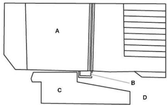
1. Position air conditioner in window
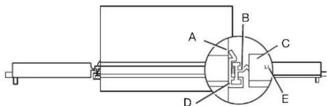
A. Air conditioner
D. "I" section
B. Side panel
E. Locking screw hole
C. Plastic frame
Using two or more people, place the air conditioner into the window opening so the bottom of the air conditioner frame is against the window sill.
2. Close window
Make sure the bottom channel is seated over the window sill as shown. Bring the window down temporarily behind the top angle channel to hold the cabinet in place. Tilt the back of the unit slightly downward to allow accumulated rain water to drain out.
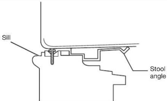
3. Secure cabinet
natural_image
Line drawing of a cabinet with two doors and a ceiling fixture (no text or symbols)NOTE: If necessary, pre-drill holes in windowsill. Fasten the cabinet to the windowsill using two 5/8" round-head screws. Add the bottom channel seal over the screws. For 22,000 and 24,000 BTU models, the bottom channel seal should sit on a gasket.
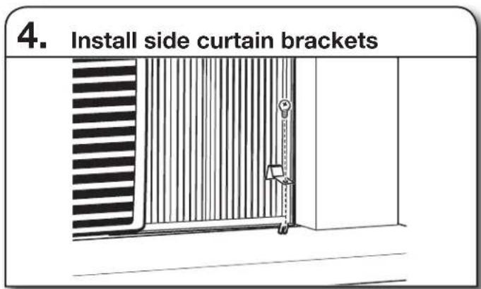
Install Support Brackets
NOTE: Attach curtains to the air conditioner before placing the air conditioner in window.
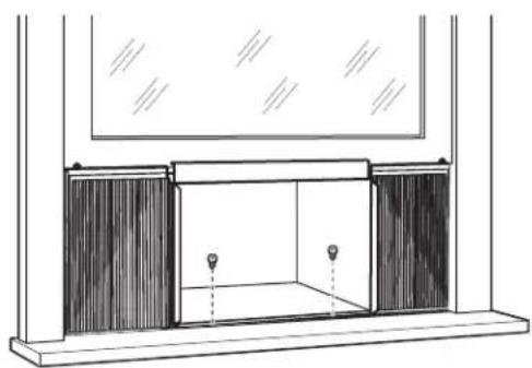
1. Mark bracket location
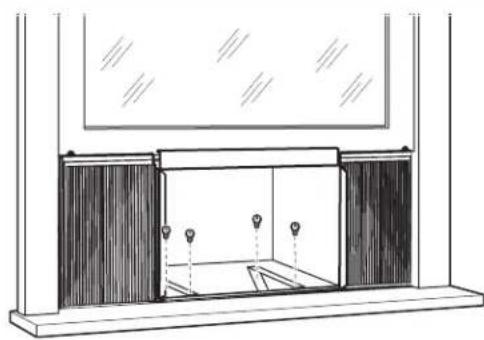
natural_image
Line drawing of a room interior with curtains and a window (no text or symbols)Hold each support bracket flush against the outside of the window sill. Tighten each bracket to the bottom of the cabinet. Mark the location of the brackets at the top level of the windowsill. Remove the brackets.
2. Assemble brackets
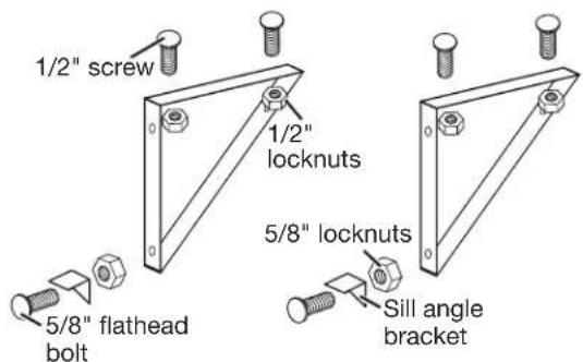
Attach the sill angle brackets to the support brackets with 1/2" screws, flat head bolts, and locknuts as shown. Hand tighten screws loosely to accommodate changes that may be required later in installation.
3. Attach assembled brackets
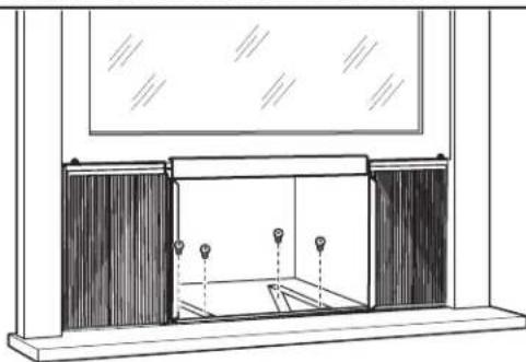
natural_image
Line drawing of a cabinet or enclosure with windows and doors, no text or symbols presentAttach the support brackets (with sill angle brackets attached) to the bottom of the cabinet with 1/2" screws and locknuts as shown. Tighten all six bolts securely.
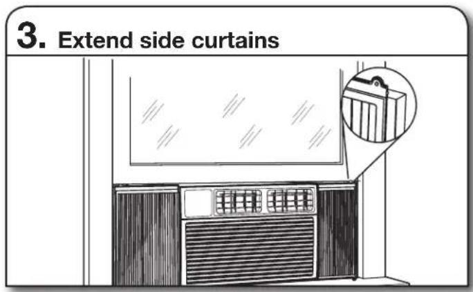
Extend Side Panels
- Loosen locking screws
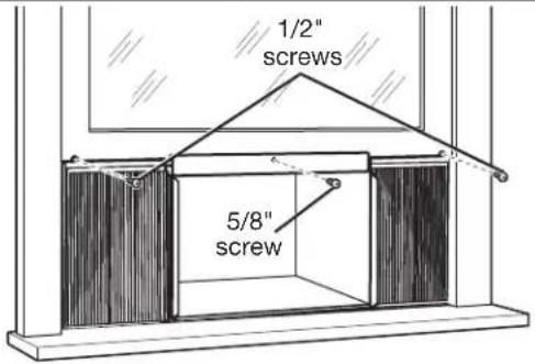
Raise the window to expose the window side panel and panel frame. Loosen the locking screws so the side panels slide easily.
2. Extend window panels
Extend each panel to completely fill the width of the window. Tighten the locking screws when the panels are fully extended.
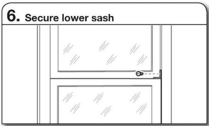
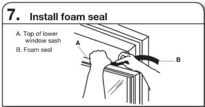
Install Window Lock and Sash Seal
NOTE: Attach curtains to the air conditioner before placing the air conditioner in window.
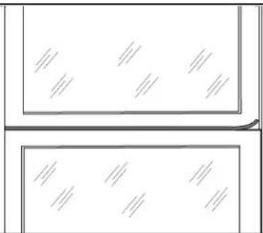
- Insert sash seal
natural_image
Two rectangular panels with diagonal lines inside, no text or symbols presentTrim the sash seal to fit the width of the window. Insert the sash seal into the space between the upper and lower sashes.
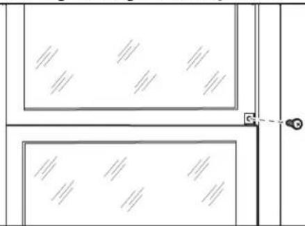
- Attach right angle safety lock
natural_image
Pure architectural floor plan lines without any text, numbers, or symbolsAttach the right angle safety lock with a 5/8" hex-head screw.
Install the Chassis into the Cabinet
WARNING
Excessive Weight Hazard
Use two or more people to move and install air conditioner.
Failure to do so can result in back or other injury.
1. Reinsert air conditioner chassis
IMPORTANT: To prevent damage to the unit, do not push on the controls or finned coils.
Using two people, lift the air conditioner chassis and carefully slide it into the cabinet. Let the front of the air conditioner hang out approximately 6" (15.24 cm). Be sure the chassis is firmly seated in the back of the cabinet.
2. Reassemble air conditioner
Insert all screws removed during window installation. Reattach the front faceplate, front panel, and air filter. Refer to the "Prepare Air Conditioner for Installation" section for more information.
WALL INSTALLATION INSTRUCTIONS—15,000-24,000 BTU MODELS
Additional Tools Required
Gather the required tools and parts before starting installation. Read and follow the instructions provided with any tools listed here.
■Wood frame
■Shims
■10 wood screws - 1" (2.54 cm) long minimum
Selecting a Wall Installation Site
The air conditioner has a slide-out chassis so that it can be installed through an outside wall.
Max wall thickness: 8" (20.32 cm)
IMPORTANT: In order to ensure proper airflow, the side louvers must never be blocked.
Wall requirements:
■Allows unblocked airflow from the rear and sides of the air conditioner
■Located near existing electrical outlets or where another outlet can or will be installed
■Does not support major structural loads, such as the frame construction at ends of windows, under truss-bearing points, etc.
■Does not have plumbing or wiring inside
■Does not have objects blocking the air vents
Preparing the Wall Installation Site
The air conditioner has a slide-out chassis, so that it can be installed through an outside wall. Prepare the wall in-frame construction (including brick and stucco veneer).
1. Cut a hole on sides of center stud
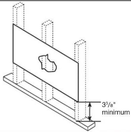
Working from inside the room, find the wall stud that is nearest to the center of the installation area. Cut a hole on each side of the center stud, leaving at least 3^3/_8 " (8.57 cm) below the hole.
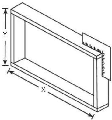
Using the below table to find installation dimensions, measure between the inside edges of every other stud.
Width X=inside model plus twice the thickness of the framing material used.
Height Y= inside model height plus twice the thickness of the framing material used.
| 15K/18K models 22 | K/24K models | |
| Inside-frame height | 18 14 " (46.4 cm) | 19 12 " (49.5 cm) |
| Inside-frame width | 23 78 " (60.6 cm) 26 | ^9/_10 " (68.3 cm) |
natural_image
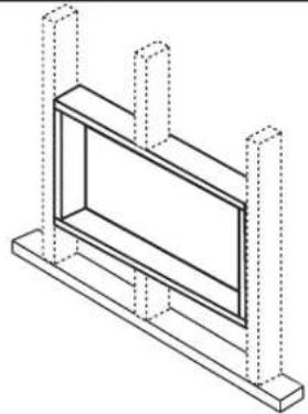
Isometric line drawing of a rectangular frame with labeled dimensions X, Y, and Z (no text or symbols beyond measurement indicators)2. Build frame
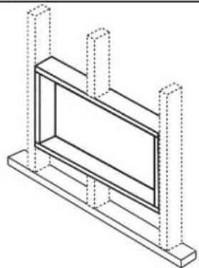
natural_image
Isometric line drawing of a rectangular frame mounted on a base, with vertical supports and no text or symbols present.Build a wooden frame with the inside dimensions of your model listed above. The frame depth should be the same as the wall thickness. Fill in extra space from the opening to the studs with wood spacers as shown.
Nail the spacers to the studs. They should be flush with the drywall.
NOTE: If the wall thickness is 8½" (21.59 cm) or more, add aluminum flashing over the bottom of the frame opening to assure water is unable to enter the area between the inner and outer wall.

Prepare and Install the Cabinet
1. Remove chassis
Slide the chassis from the cabinet. See the "Prepare Air Conditioner for Installation" section for more details.
2. Place and position cabinet
Gap size 5/16" to 3/8"
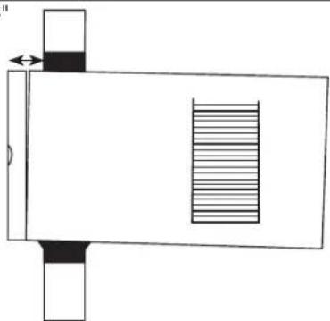
natural_image
Pure technical diagram of a rectangular container with internal striped pattern and side supports (no text or symbols)Place the cabinet into the opening with the bottom channel resting firmly on the bottom rail of the wood frame. Position the cabinet so it is properly tilted for water removal.
3. Secure bottom channel to frame
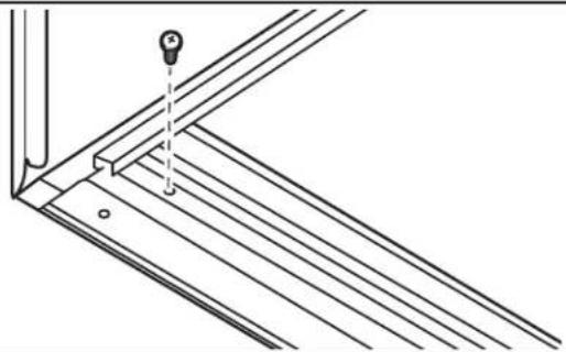
natural_image
Technical line drawing of a structural bracket with diagonal braces and a vertical pin (no text or symbols)Secure the bottom channel to the wood frame with two large 1" (2.5 cm) wood screws.
- Place and position cabinet
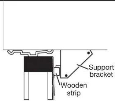
Assemble brackets. See "Install Support Brackets" in the "Window Installation" section. Nail a wooden strip to the outside wall to be used in conjunction with the angled sill support brackets.
5. Secure cabinet and install chassis
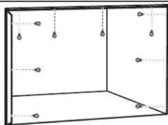
natural_image
Simple line drawing of a 3D rectangular room with hanging lights and dashed lines indicating positions (no text or symbols)Screw or nail the cabinet to the wooden frame using shims if the frame is oversized to eliminate possible noise. Remember to maintain proper slope for water elimination.
Reinstall the chassis into the cabinet. See the "Install the Chassis into the Cabinet" section.
Masonry Construction
- Cut or build a wall opening in the masonry wall similar to the frame contraction. See the "Wall Installation Instructions – 240 V Models" section for a wall thickness greater than 8 12 " (21.59 cm).
- Secure the cabinet in place using masonry nails or masonry anchor screws. Or build a frame using the instructions found in the "Wall Installation Instructions – 240 V Models" section.
- Make sure the masonry above the cabinet is supported well. Use the existing holes in the cabinet or additional drilled holes to fasten the cabinet at various positions. Make sure that the side louvers are clear of any obstructions.
- Install the exterior cabinet support brackets according to "Prepare and Install the Cabinet" in the "Wall Installation Instructions - 240 V Models" section. Caulk or flash with aluminum if needed. This will provide a tight seal around the top and sides of the cabinet.
- For a more aesthetically pleasing installation, apply wood trim molding around the sides of the cabinet without obstructing the side louvers.
USING YOUR AIR CONDITIONER
Operating your air conditioner properly helps you to obtain the best possible results.
This section explains proper air conditioner operation.
IMPORTANT:
■If you turn off the air conditioner, wait at least 3 minutes before turning it back on. This prevents the air conditioner from blowing a fuse or tripping a circuit breaker.
■Do not try to operate your air conditioner in the Cool mode when outside temperature is below 65^ F ( 18^ C). The inside evaporator coil will freeze up, and the air conditioner will not operate properly.
NOTE: In the event of a power failure, your air conditioner will operate at the previous settings when the power is restored.
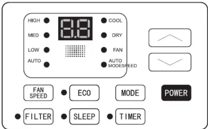
Turning on the Air Conditioner
- Press POWER to turn on air conditioner.
- Press POWER again to turn off the air conditioner.
POWER
Selecting the Mode
- Press MODE to cycle through modes.
- Choose Cool, Dry, or Fan.
■Cool—Cools the room and reduces air humidity. Press MODE to activate the cooling function. Press the up or down arrow button to adjust the temperature.
■Dry Mode—Reduces the humidity of the air. Press MODE to set the Dry mode. An automatic function of alternating cooling cycles and air fan is activated.
■Fan—Only the fan runs. Press MODE to set the Fan mode. Press FAN SPEED to select High, Med, and Low. The remote control stores the speed set in the previous mode of operation. In Auto mode, the unit automatically chooses the fan speed and the mode of operation (Cool, Dry, or Fan).
NOTE: After 5 seconds, display will show the current room temperature.
Features
■Eco—Conserves energy by turning off compressor when room reaches desired temperature. The fan motor will run for 10 minutes, stop for 20 seconds, then run again. The compressor will turn back on when the room temperature rises above the set temperature. Press ECO to turn Eco feature on and off. When the unit is in Eco mode, the light will turn on.
HIGH

■Sleep—Automatically adjusts the temperature and fan speed to make the room more comfortable during the night. Press and hold the SLEEP button for 10 seconds until the sleep light turns on. All of the left lights will turn off. The set temperature will automatically raise by 1.8^ F ( 1^ C) every 30-60 minutes. At most, the temperature will change six times until the temperature reaches 82^ F ( 28^ C). Running time depends upon the set temperature.
MED

LOW

AUTO SPEED

NOTE: After 5 seconds, display will show the current room temperature.
Selecting the Fan Speed
- Press FAN until the LED indicator for the desired setting is lit.
- Choose Low, Med, or High.
■Low—Low fan speed
■Med—Normal fan speed
■High—Maximum fan speed
NOTES:
■Auto fan speed and temperature cannot be selected in Fan Only mode.
■In Eco and Sleep modes, Auto fan speed is selected automatically.
■After 5 seconds, the display will show the current room temperature.
Adjusting the Temperature
Press the up arrow button to increase the set temperature.
Press the down arrow button to decrease the set temperature.
NOTE: After 5 seconds, the display on the air conditioner control panel will show the current room temperature.

Using the Timer
Delayed Shutoff:
Use the timer to set the air conditioner to turn off automatically after a 0.5- to 24-hour delay (the air conditioner must be on):
- Press TIMER. The display will show remaining time before the air conditioner will turn off.
- Press the up or down arrow button to change the delayed shut-off time from 0.5 to 24 hours. The time can be set in 0.5-hour increments below 10 hours and 1-hour increments for 10 hours or above.
- Press TIMER again to confirm setting.
NOTE: The Set light will turn on while setting.
Delayed Start:
You can also set the air conditioner to turn on automatically after a 0.5- to 24-hour delay.
NOTE: After the set delay, the air conditioner will turn on with the previous settings. Change the mode, fan speed, and/or temperature before setting the timer, if desired.
- Turn off the air conditioner.
- Press TIMER. Set the temperature by pressing the up or down arrow button.
- Press TIMER a second time to set the rest time. Press the up or down arrow button to change the delay time from 0.5 to 24 hours, then press TIMER again.
- Press TIMER again while the time remaining is shown on the display.
To Cancel Timer:
After the timer has been set, press TIMER.
Changing Air Direction
Use tab to adjust air direction
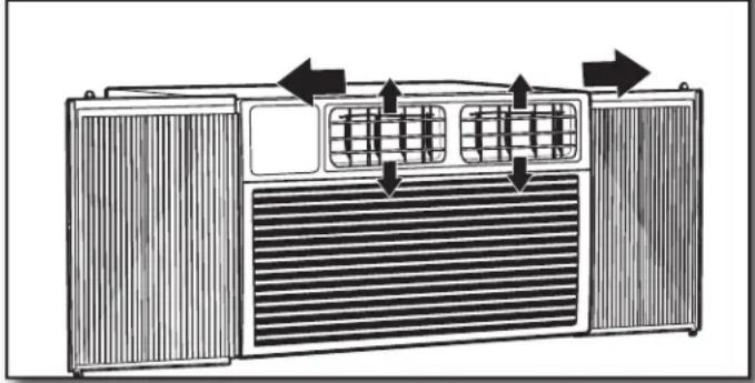
natural_image
Diagram of an air conditioner unit with ventilation grilles and airflow arrows (no text or labels)Use the thumb wheel on the vent louvers to adjust the air direction left or right.
Normal Operating Sounds
When your air conditioner is operating normally, you may hear sounds such as:
■Droplets of water hitting the condenser, causing a pinging or clicking sound. The water droplets help cool the condenser.
■Air movement from the fan.
■Clicks from the thermostat cycle.
■Vibrations or noise due to poor wall or window construction.
■A high-pitched hum or pulsating noise caused by the modern high-efficiency compressor cycling on and off.
■Water will collect in the base pan during rain or days of high humidity. The water may overflow and drip from the outside part of the unit.
Clean Filter Reminder
To help maximize energy efficiency, this air conditioner features a Clear Filter reminder. After 500 hours of operation, FILTER will illuminate as a reminder that it is time to

clean the filter. Once the light is illuminated, it can be turned off by pressing the FILTER button. See the "Air Conditioner Care" section for instructions on how to clean the filter.
Using the Remote Control
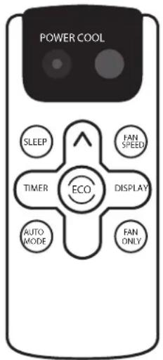
Power
- Press POWER to turn on air conditioner.
- Press POWER again to turn off the air conditioner.
Cool
Press COOL to enter Cool mode.


Fan Speed
- Press FAN SPEED until you see the bar LED on the air conditioner control panel display for the desired setting.

- Choose Low, Medium, or High.
NOTES:
■Auto fan speed and Temperature cannot be selected in Fan mode.
In Energy Saver (on some models) and Cool modes, Auto fan speed is selected automatically.
Eco
■Conserves energy by turning off compressor when room reaches desired temperature. The fan motor will run for 10 minutes, stop for 20 seconds, then run again. The compressor will turn back on when the room temperature rises above the set temperature. Press ECO to turn Eco feature on and off. When the unit is in Eco mode, the light will turn on.

Adjusting Temperature
Press the up arrow button to increase the set temperature. Press the down button to decrease the set temperature.
NOTE: After 5 seconds, the display on the air conditioner control panel will show the current room temperature.

Sleep
Automatically adjusts the temperature and fan speed to make the room more comfortable during the night. Press and hold the SLEEP button for 10 seconds until the Sleep light turns on. All of the left lights will turn off. The set temperature will automatically raise by 1.8^ F ( 1^ C) every 30-60 minutes. At most, the temperature will change six times until the temperature reaches 82^ F ( 28^ C). Running time depends upon the set temperature.

Timer
Delayed Shutoff:
Use the timer to set the air conditioner to turn off automatically after a 0.5- to 24-hour delay (the air conditioner must be on):
- Press TIMER. The display will show remaining time before the air conditioner will turn off.
- Press the up or down arrow button to change the delayed shut-off time from 0.5 to 24 hours. The time can be set in 0.5-hour increments below 10 hours and 1-hour increments for 10 hours or above.

- Press TIMER again to confirm setting.
NOTE: The Set light will turn on while setting.
Delayed Start:
You can also set the air conditioner to turn on automatically after a 0.5- to 24-hour delay.
NOTE: After the set delay, the air conditioner will turn on with the previous settings. Change the mode, fan speed, and/or temperature before setting the timer, if desired.
- Turn off the air conditioner.
- Press TIMER. Set the temperature by pressing the up or down arrow button.
- Press TIMER a second time to set the rest time. Press the up or down arrow button to change the delay time from 0.5 to 24 hours, then press TIMER again.
- Press TIMER again while the time remaining is shown on the display.
To Cancel Timer:
After the timer has been set, press TIMER.
Auto:
Press AUTO MODE to enter into Auto mode. In this mode, the fan speed and temperature are set automatically according to the room temperature as tested by the indoor temperature sensor.

Display:
Press DISPLAY to switch on/off all lights or the LED display.

Fan only:
Press the Fan Only button to enter Fan Only mode.

Replacing the battery
Remove and replace batteries
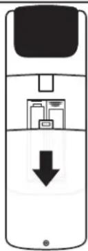
natural_image
Diagram of a mobile phone showing internal components and a downward arrow (no text or symbols)Use a small Phillips screwdriver to loosen the battery cover screw. Slide the battery cover down with two thumbs to remove. Remove and properly dispose of old batteries, then replace with two new AAA batteries. Replace the battery cover and tighten the screw.
AIR CONDITIONER CARE
Your new air conditioner is designed to give you many years of dependable service. This section tells you how to clean and care for your air conditioner properly.
Air Filter Removal—Top Insert
On some models, the air filter is located behind the intake grille of air conditioner.
1. Removing the intake grille
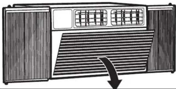
natural_image
Diagram of an air conditioner unit with ventilation grilles and a downward arrow indicating airflow (no text or symbols)Turn off the air conditioner.
Remove the air filter by pressing down on the tabs on the air intake grille and pulling the grille away from the air conditioner.
2. Removing the air filter
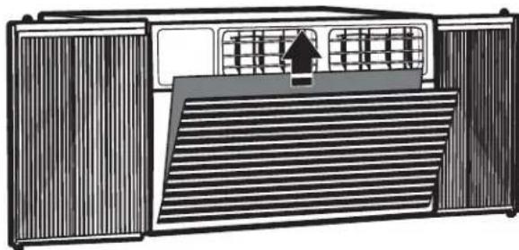
natural_image
Diagram of an air vent system with ventilation grilles and a directional arrow (no text or labels)Remove the filter from the grille by lifting to release the slotted tabs on the top and bottom of the grille.
Reinstalling the air filter:
- Reattach the air filter to the air intake grille.
- Insert the air intake grille into the slots on the air conditioner and snap into place.
Air Filter Removal—Side Insert
On some models, the air filter slides out the side of the intake grille.
1. Removing the air filter
natural_image
Top-down schematic of an air conditioner unit with ventilation grilles and buttons, no text or symbols presentRemove the filter by grasping the tab on the filter and pulling it out of the grille to the side.
Reinstalling the air filter:
- Slide the filter back into the grille.
Cleaning the Air Filter
The air filter is removable for easy cleaning. A clean filter helps remove dust, lint, and other particles from the air and is important for best cooling and operating efficiency. Check the filter at least once per month to see whether it needs cleaning.
NOTE: Do not operate the air conditioner without the filter in place. Doing so will degrade the unit performance over time. Use a vacuum cleaner to clean air filter. If the air filter is very dirty, wash it in warm water with a mild detergent.
NOTE: Do not wash the air filter in the dishwasher or use any chemical cleaners; it may damage the filter. Air dry the air filter completely before replacing to ensure maximum efficiency.
Cleaning the Front Panel
- Unplug the air conditioner to prevent shock or a fire hazard.
- Wipe the front panel with a soft, damp cloth.
- Air dry the front panel completely.
Repairing Paint Damage
Check once or twice a year for paint damage. This is very important, especially in areas near saltwater or where rust is a problem. If needed, touch up with a good grade enamel paint.
Winter Storage
- Remove the air conditioner according to the installation instructions.
- Cover the air conditioner with plastic or place it back into the original box.
TROUBLESHOOTING
Before calling for service, try the suggestions below to see whether you can solve your problem without outside help.
WARNING

Electrical Shock Hazard
Plug into a grounded 3 prong outlet.
Do not remove ground prong.
Do not use an adapter.
Do not use an extension cord.
Failure to follow these instructions can result in death, fire, or electrical shock.
| PROBLEM POSSIBLE CA | USES RECOMMENDED SOLUTIONS | |
| The Air Conditioner Will Not Start | The air conditioner is unplugged. Make sure the power supply cord is plugged into a grounded 3 prong outlet. | |
| The fuse is blown/circuit breaker is tripped. Check the house fuse/circuit breaker box and replace the fuse or reset the breaker. | ||
| Power failure The unit will automatically restart when power is restored. There is a protective time delay (approximately 3 minutes) to prevent tripping of the compressor overload. The unit may not start normal cooling for 3 minutes after it is turned back on. | ||
| The power cord reset button is tripped. Press the reset button located on the power cord plug. If the reset button will not stay engaged, discontinue use of the air conditioner and contact a qualified service technician. | ||
| The Air Conditioner Is Not Cooling Properly | Airflow is restricted. Make sure there are no curtains, blinds, or furniture blocking the front of the air conditioner. | |
| The temperature control is not set correctly. Lower the set thermostat temperature. | ||
| The air filter is dirty. Clean the filter. See the “Air Conditioner Care” section. | ||
| The room is too warm. Allow time for the room to cool down after turning on the air conditioner. | ||
| Cold air is escaping. Close all open doors and/or windows where warm air may be entering. | ||
| The cooling coils are frozen. See “The Air Conditioner Is Freezing Up” below. | ||
| The Air Conditioner Is Freezing Up | Ice is blocking the airflow. Turn off the unit and allow it to thaw until the ice has melted, then operate on a higher fan speed. If this continues to occur, contact customer service for additional help. | |
| The Remote Control Is Not Working | Batteries are inserted incorrectly. | Check that the batteries are inserted in the correct direction. |
| Batteries are dead. | Replace the batteries and dispose of them in a responsible manner. | |
| Water Is Dripping From the Unit on the Outdoor Side | The weather is hot and humid. This is normal | during periods of high humidity.NOTE: Do not drill a hole into the bottom of the metal base pan; doing so will reduce cooling performance. |
| Water Is Dripping Inside the Room | The air conditioner is not properly leveled. | The air conditioner should slope slightly downward toward the outside. Level the air conditioner to provide a downward slope toward the outside to ensure proper drainage. See the “Installation Instructions” section.NOTE: Do not drill a hole into the bottom of the metal base pan; doing so will reduce cooling performance. |
| Water Collects in the Base Pan | Moisture removed from the air is collecting in the base pan. | This is normal. Water that collects in the base pan will evaporate to the outside air. This helps with the unit's cooling process.NOTE: Do not drill a hole into the bottom of the metal base pan; doing so will reduce cooling performance. |
ASSISTANCE OR SERVICE
Before calling for assistance or service, please check the "Troubleshooting" section. It may save you the cost of a service call. If you still need help, follow the instructions below.
When calling, please know the purchase date and the complete model and serial numbers of your appliance. This information will help us to better respond to your request.
In the USA
Call XLS Products Customer Service toll free: 1-800-207-1156.
Our consultants provide assistance with:
■ Features and specifications on our full line of appliances.
■ Installation information.
■ Use and maintenance procedures.
■ Accessory and repair parts.
■ Specialized customer assistance.
■ Referrals to local dealers, repair parts distributors, and service companies. XLS Products-designated service technicians are trained to fulfill the product warranty and provide after-warranty service, anywhere in the United States.
For further assistance:
If you need further assistance, you can write to XLS Products with any questions or concerns at:
XLS Products, Inc.
Customer Service
P.O. Box 16262
Philadelphia, PA 19114-0262
Please include a daytime phone number in your correspondence.
In Canada
Call XLS Products Customer Service toll free: 1-800-207-1156.
Our consultants provide assistance with:
■ Features and specifications on our full line of appliances.
■ Use and maintenance procedures.
■ Accessory and repair parts.
■ Referrals to local dealers, repair parts distributors, and service companies. XLS Products-designated service technicians are trained to fulfill the product warranty and provide after-warranty service, anywhere in Canada.
For further assistance:
If you need further assistance, you can write to XLS Products with any questions or concerns at:
XLS Products, Inc.
Customer Service
P.O. Box 16262
Philadelphia, PA 19114-0262
Please include a daytime phone number in your correspondence.
XLS PRODUCTS WARRANTY FOR
AMANA® AIR CONDITIONERS
ONE YEAR LIMITED WARRANTY
For one year from the date of purchase, when this product is operated and maintained according to instructions attached to or furnished with the product, XLS Products will pay for replacement parts and repair labor to correct defects in materials or workmanship or replace the product at our discretion. Service must be provided by a XLS Products designated service company. This warranty does not cover the air filter.
ITEMS XLS PRODUCTS WILL NOT PAY FOR
- Service calls to correct the installation of your product, instruct you how to use your product, to replace house fuses or reset circuit breakers, replace or clean filters, or correct house wiring.
- Service calls to repair or replace air filters. Those consumable parts are excluded from warranty coverage.
- Repairs when your product is used for other than normal, single-family household use.
- Damage resulting from accident, alteration, misuse, abuse, fire, flood, acts of God, improper installation, installation not in accordance with electrical or plumbing codes, or use of products not approved by XLS Products.
- Replacement parts or repair labor costs for units operated outside the United States or Canada.
- Pickup and delivery. This product is designed to be repaired in the home.
- Repairs to parts or systems resulting from unauthorized modifications made to the appliance.
- Expenses for travel and transportation for product service in remote locations.
- The removal and reinstallation of your appliance if it is installed in an inaccessible location or is not installed in accordance with published installation instructions.
DISCLAIMER OF IMPLIED WARRANTIES; LIMITATION OF REMEDIES
CUSTOMER'S SOLE AND EXCLUSIVE REMEDY UNDER THIS LIMITED WARRANTY SHALL BE PRODUCT REPAIR AS PROVIDED HEREIN. IMPLIED WARRANTIES, INCLUDING WARRANTIES OF MERCHANTABILITY OR FITNESS FOR A PARTICULAR PURPOSE, ARE LIMITED TO ONE YEAR OR THE SHORTEST PERIOD ALLOWED BY LAW. XLS PRODUCTS SHALL NOT BE LIABLE FOR INCIDENTAL OR CONSEQUENTIAL DAMAGES. SOME STATES AND PROVINCES DO NOT ALLOW THE EXCLUSION OR LIMITATION OF INCIDENTAL OR CONSEQUENTIAL DAMAGES, OR LIMITATIONS ON THE DURATION OF IMPLIED WARRANTIES OF MERCHANTABILITY OR FITNESS, SO THESE EXCLUSIONS OR LIMITATIONS MAY NOT APPLY TO YOU. THIS WARRANTY GIVES YOU SPECIFIC LEGAL RIGHTS AND YOU MAY ALSO HAVE OTHER RIGHTS, WHICH VARY, FROM STATE TO STATE OR PROVINCE TO PROVINCE.
Outside the 50 United States and Canada, this warranty does not apply. Contact your authorized XLS Products dealer to determine if another warranty applies.
If you need service, first see the “Troubleshooting” section of the Use & Care Guide. After checking “Troubleshooting,” additional help can be found by checking the “Assistance or Service” section or by calling XLS Products. In the U.S.A., call 1-800-207-1156. In Canada, call 1-800-207-1156.
Keep this book and your sales slip together for future reference. You must provide proof of purchase or installation date for in-warranty service.
Write down the following information about your air conditioner to better help you obtain assistance or service if you ever need it. You will need to know your complete model number and serial number. You can find this information on the model and serial number label located on the product.
Dealer name ____
Address ____
Phone number ____
Model number ____
Serial number ____
Purchase date ____
National Fire Protection Association
1 Batterymarch Park
Quincy, MA 02269
natural_image
Line drawing of a portable air conditioner unit with ventilation grilles and ventilation grilles (no text or symbols)natural_image
Line drawing of a microwave oven with ventilation grilles and lid (no text or symbols)natural_image
Line drawing of a microwave oven with ventilation grilles and top-mounted dish (no text or symbols)natural_image
Line drawing of a portable air conditioner unit with ventilation grilles and front panel (no text or symbols)natural_image
Line drawing of a room interior with a window, cabinet, and wall-mounted air conditioner (no text or symbols)natural_image
Pure architectural line drawing of two doors with windows and a door, no text or symbols presentnatural_image
Simple line drawing of a door with vertical stripes and a hanging weight (no text or symbols)natural_image
Technical line drawing of an air conditioner unit with ventilation grilles and a mounted panel (no text or symbols)natural_image
Line drawing of a portable air conditioner unit with ventilation grilles and ventilation grilles (no text or symbols)natural_image
Illustration of a portable air conditioner unit with ventilation grilles and slatted back panel (no text or symbols)natural_image
Line drawing of a portable air conditioner unit with ventilation grilles and control panel (no text or symbols)natural_image
Line drawing of a portable air conditioner unit with ventilation grilles and control panel (no text or symbols)natural_image
Illustration of a portable air conditioner unit with ventilation grilles and control panel (no text or symbols)natural_image
Technical line drawing of a rectangular industrial fan or enclosure with ventilation grilles and heat sinks (no text or symbols)natural_image
Line drawing of a microwave oven with ventilation grilles and a grid-patterned front panel (no text or symbols)natural_image
Line drawing of a rectangular industrial enclosure with ventilation grilles and three hanging lights (no text or symbols)natural_image
Line drawing of a simple indoor enclosure with two windows and a ceiling fixture (no text or symbols)natural_image
Line drawing of a window with curtains and a ceiling fixture (no text or symbols)3. Fixer supports assemblés

natural_image
Line drawing of a cabinet or enclosure with windows and doors, no text or symbols presentnatural_image
Two rectangular panels with diagonal lines inside, no text or symbols presentnatural_image
Pure architectural floor plan lines without any text, numbers, or symbolsnatural_image
Isometric line drawing of a rectangular frame with X and Y axis labels (no text or symbols beyond measurement indicators)natural_image
Isometric line drawing of a rectangular frame mounted on a base, with vertical supports and dotted lines indicating hidden edges (no text or symbols)natural_image
Technical line drawing of a structural bracket with diagonal braces and a vertical bolt (no text or symbols)natural_image
Simple line drawing of a room with hanging lights and dashed lines indicating positions (no text or symbols)natural_image
Diagram of an air conditioner unit with heat exchangers and ventilation grilles (no text or labels)natural_image
Diagram of a mobile phone showing internal components and a downward arrow (no text or symbols)natural_image
Diagram of an air conditioner unit with ventilation grilles and a downward arrow indicating airflow (no text or symbols)natural_image
Diagram of an air vent system with ventilation grilles and a directional arrow (no text or labels)natural_image
Top-down schematic of an air conditioner unit with ventilation grilles and fan (no text or labels)ASSISTANCE OU SERVICE
Philadelphia, PA 19114-0262
Philadelphia, PA 19114-0262
Btu de Modelos - 6,000; 8,000; 10,000; 12,000; 15,000

Todos modelos -
National Fire Protection Association
1 Batterymarch Park
Quincy, MA 02269
natural_image
Three technical illustrations of different tool designs: a screwdriver, a pair of scissors, and a rectangular electronic component (no text or symbols)Destornillador Phillips
Tijeras
Nivel

natural_image
Three technical illustrations: a tape measure, a drill bit, and a pencil (no text or symbols present)natural_image
Line drawings of three different wrench tools: a standard screwdriver, an adjustable wrench, and a compact wrench (no text or symbols present)natural_image
Line drawing of a portable air conditioner unit with ventilation grilles and ventilation grilles (no text or symbols)natural_image
Line drawing of a microwave oven with ventilation grilles and lid (no text or symbols)natural_image
Line drawing of a microwave oven with ventilation grilles and top-mounted dish (no text or symbols)natural_image
Line drawing of an air conditioner unit with a magnified inset showing the exterior wall (no text or symbols)natural_image
Line drawing of a door with vertical slats and a hanging lock, no text or symbols presentnatural_image
Technical line drawing of an air conditioner unit with ventilation grilles and a mounted panel (no text or symbols)natural_image
Pure architectural floor plan lines without any text, numbers, or symbolsnatural_image
Line drawing of a portable air conditioner unit with ventilation grilles and ventilation grilles (no text or symbols)natural_image
Line drawing of a portable air conditioner unit with ventilation grilles and slatted back panel (no text or symbols)natural_image
Line drawing of a portable air conditioner unit with ventilation grilles and control panel (no text or symbols)natural_image
Line drawing of a portable air conditioner unit with ventilation grilles and grid panels (no text or symbols)natural_image
Illustration of a portable air conditioner unit with ventilation grilles and control panel (no text or symbols)natural_image
Technical line drawing of a server rack unit with ventilation grilles and ventilation grilles (no text or symbols)natural_image
Line drawing of a microwave oven with ventilation grilles and a grid-patterned front panel (no text or symbols)IMPORTANTE:
natural_image
Line drawing of a rectangular industrial enclosure with ventilation grilles and three light bulbs on top (no text or symbols)natural_image
Line drawing of a cabinet with two doors and a ceiling fixture (no text or symbols)natural_image
Line drawing of a cabinet interior with doors and windows, no text or symbols presentnatural_image
Line drawing of a cabinet with doors, windows, and ceiling-mounted fixtures (no text or symbols)natural_image
Pure architectural floor plan lines without any text, numbers, or symbolsnatural_image
Simple line drawing of two rectangular windows with diagonal lines and a small lock on the right wall (no text or symbols)natural_image
Isometric line drawing of a rectangular frame with labeled dimensions X, Y, and Z (no text or symbols beyond measurement indicators)2. Construya marco
natural_image
Isometric line drawing of a rectangular frame mounted on a base, with vertical supports (no text or symbols)natural_image
Technical line drawing of a structural joint or bracket assembly (no text or symbols)natural_image
Simple line drawing of a 3D room with hanging lights and dashed lines indicating positions (no text or symbols)natural_image
Diagram of an air conditioner unit with heat exchangers and ventilation grilles (no text or labels)natural_image
Diagram of a mobile phone with a downward arrow indicating download or exit (no text or symbols present)natural_image
Diagram of an air conditioner unit with ventilation grilles and a downward arrow indicating airflow (no text or symbols)natural_image
Diagram of a ventilation system with heat exchangers and airflow path (no text or labels)natural_image
Top-down schematic of an air conditioner unit with ventilation grilles and heat sinks (no text or labels)Philadelphia, PA 19114-0262
Philadelphia, PA 19114-0262
®/TM ©2018 Amana. All rights reserved. Manufactured under license by XLS Products, Pennsylvania.
- Table of Contents
- Climatiseur
- Your safety and the safety of others are very important.
- ! DANGER
- WARNING
- IMPORTANT SAFETY INSTRUCTIONS
- SAVE THESE INSTRUCTIONS
- INSTALLATION REQUIREMENTS
- Electrical Requirements—All Models
- Electrical Shock Hazard
- Electrical Requirements—115 V Models
- All models -
- 6,000-8,000 BTU models -
- 10,000-15,000 BTU models -
- Electrical Requirements—230 V Models
- Recommended Grounding Method
- Power Supply Cord—All Models
- To test your power supply cord:
- NOTES:
- Tools Required—All Models
- Parts Supplied: 6,000-12,000 BTU models
- Parts Supplied—15,000-24,000 BTU Models
- Location Requirements—Window Installation
- Window Opening Measurements
- Prepare Window Opening
- Measure and mark center line
- Attach upper foam seal
- Preparing Window with Storm Window or Other Obstruction
- Measure size of spacer needed
- Place block on windowsill
- INSTALLATION INSTRUCTIONS—6,000-12,000 BTU MODELS
- Prepare Air Conditioner for Installation
- Unpack the Air Conditioner
- Remove Packaging Materials:
- Install top channel
- Attach screws
- Install Side Curtains
- Install side curtain
- Insert curtain frame into channels
- Install Air Conditioner in Window
- IMPORTANT:
- Position air conditioner in window
- Lower window sash into place
- WINDOW INSTALLATION INSTRUCTIONS—15,000-24,000 BTU MODELS
- Remove filter and front panel
- Remove faceplate screws
- Remove faceplate
- Remove control panel screw
- Install Top Channel and Side Bracket
- Attach foam gasket
- Close window
- Secure cabinet
- Install Support Brackets
- Mark bracket location
- Assemble brackets
- Attach assembled brackets
- Extend Side Panels
- Extend window panels
- Install Window Lock and Sash Seal
- Install the Chassis into the Cabinet
- Reinsert air conditioner chassis
- Reassemble air conditioner
- WALL INSTALLATION INSTRUCTIONS—15,000-24,000 BTU MODELS
- Additional Tools Required
- Selecting a Wall Installation Site
- Wall requirements:
- Preparing the Wall Installation Site
- Cut a hole on sides of center stud
- Build frame
- Remove chassis
- Place and position cabinet
- Secure bottom channel to frame
- Secure cabinet and install chassis
- Masonry Construction
- USING YOUR AIR CONDITIONER
- Turning on the Air Conditioner
- POWER
- Selecting the Mode
- Features
- Selecting the Fan Speed
- Adjusting the Temperature
- Using the Timer
- Delayed Shutoff:
- Delayed Start:
- To Cancel Timer:
- Changing Air Direction
- Normal Operating Sounds
- Clean Filter Reminder
- Using the Remote Control
- Cool
- Fan Speed
- Eco
- Adjusting Temperature
- Sleep
- Timer
- Auto:
- Display:
- Fan only:
- Replacing the battery
- Remove and replace batteries
- AIR CONDITIONER CARE
- Air Filter Removal—Top Insert
- Removing the intake grille
- Removing the air filter
- Reinstalling the air filter:
- Air Filter Removal—Side Insert
- Removing the air filter
- Cleaning the Air Filter
- Cleaning the Front Panel
- Repairing Paint Damage
- Winter Storage
- TROUBLESHOOTING
- ASSISTANCE OR SERVICE
- In the USA
- Call XLS Products Customer Service toll free: 1-800-207-1156.
- For further assistance:
- In Canada
- XLS PRODUCTS WARRANTY FOR
- AMANA® AIR CONDITIONERS
- ONE YEAR LIMITED WARRANTY
- ITEMS XLS PRODUCTS WILL NOT PAY FOR
- DISCLAIMER OF IMPLIED WARRANTIES; LIMITATION OF REMEDIES
- Fixer supports assemblés
- ASSISTANCE OU SERVICE
- Todos modelos -
- IMPORTANTE:
- Construya marco
Brand : AMANA
Model : AMAP151CW
Category : Air Conditioning