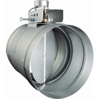
MD8TU - Ventilation system BEST - Free user manual and instructions
Find the device manual for free MD8TU BEST in PDF.



| Product Type | Automatic make-up air damper for kitchen range hood |
| Model | MD8TU (8 inches / 20.3 cm) |
| Brand | BEST (by Broan) |
| Power Supply | 24 V AC via included transformer |
| Duct Dimensions | 8 in (20.3 cm) diameter |
| Included Components | Motorized damper, transformer, pressure switch, probe, 1/4 in ID PVC tube (30 cm), gasket, 6 sheet metal screws |
| Main Function | Allows fresh outdoor air intake when a compatible hood (BEST, Broan Elite, Broan) is operating |
| Trigger Method | By pressure switch detecting an increase in static pressure (≥ 0.05 in Ps) |
| Intended Use | Installation in a residence, protected from moisture, accessible for inspection |
| Regular Maintenance | Clean exterior bird screen, clean/replace filters, remove snow/debris, annual inspection by a professional |
| Safety - Power Disconnect | Disconnect power at the electrical panel before any maintenance or cleaning |
| Safety - Installation | Performed by a qualified professional, in accordance with local codes (NFPA, ASHRAE, building codes) |
| Minimum Air Intake Distance | 10 ft (3 m) from any combustion appliance vent, chimney, bathroom/kitchen vent |
| Minimum Air Intake Height | 1 ft (30 cm) above ground |
| Undesired Triggering | Possible in extreme conditions; can be resolved by adding a backdraft damper |
| Available Replacement Parts | Pressure switch assembly (97018853), 24 V transformer (97013273), motorized damper 6/8/10 in (99527207/08/460) |
| Recommended Wall Cap Compatibility | Broan models: 641FA (6 in), 643FA (8 in), WC638, 639, etc. |
| Minimum Return Air Temperature | Must comply with the heating/cooling system manufacturer's requirements |
| Warranty | See www.broan.ca for warranty statement |
Frequently Asked Questions - MD8TU BEST
User questions about MD8TU BEST
0 question about this device. Answer the ones you know or ask your own.
Ask a new question about this device
Download the instructions for your Ventilation system in PDF format for free! Find your manual MD8TU - BEST and take your electronic device back in hand. On this page are published all the documents necessary for the use of your device. MD8TU by BEST.
USER MANUAL MD8TU BEST
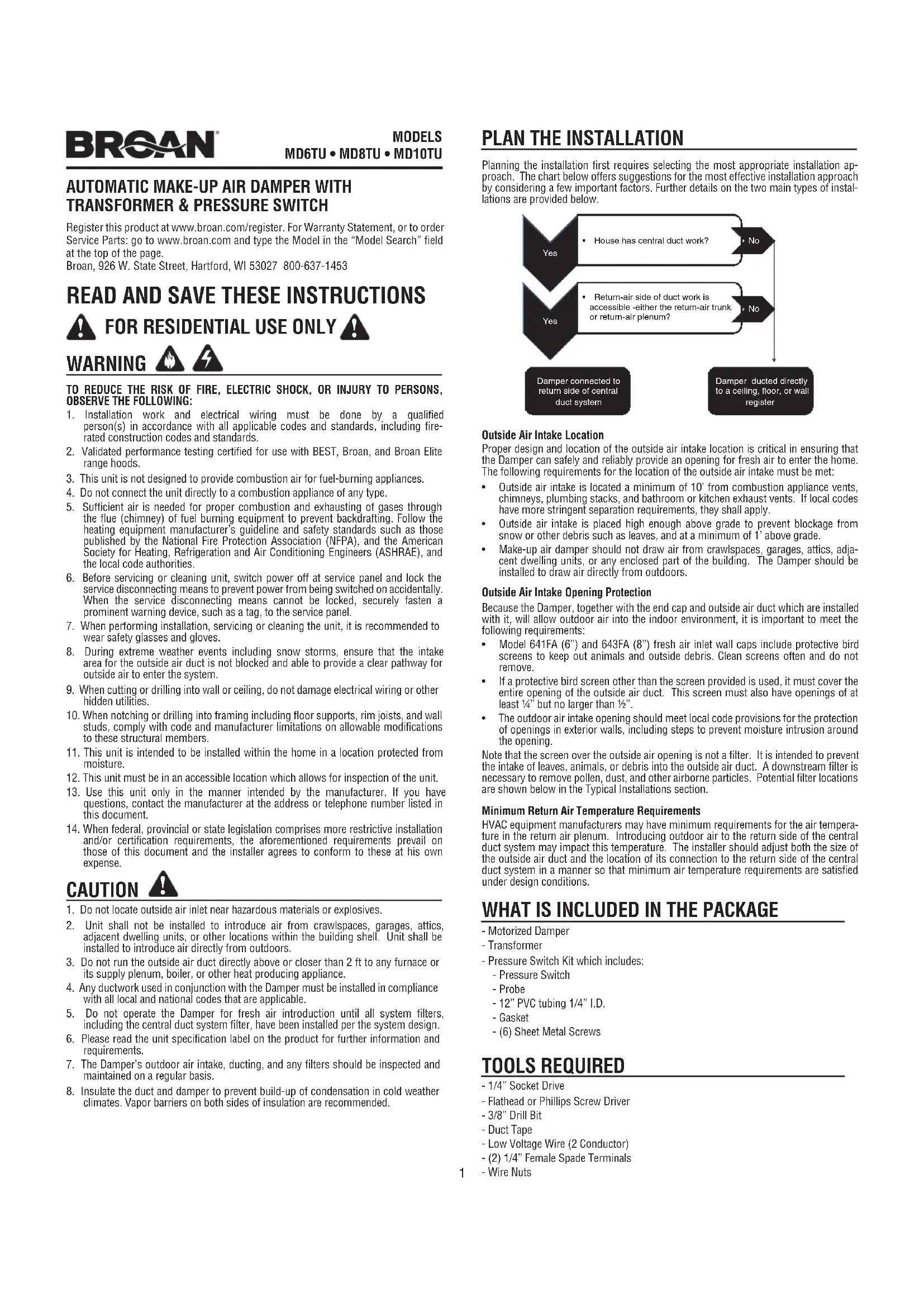
AUTOMATIC MAKE-UP AIR DAMPER WITH TRANSFORMER & PRESSURE SWITCH
Register this product at www.broan.com/register. For Warranty Statement, or to order Service Parts: go to www.broan.com and type the Model in the "Model Search" field at the top of the page.
Broan, 926 W. State Street, Hartford, WI 53027 800-637-1453
READ AND SAVE THESE INSTRUCTIONS

- Installation work and electrical wiring must be done by a qualified person(s) in accordance with all applicable codes and standards, including fire-rated construction codes and standards.
- Validated performance testing certified for use with BEST, Broan, and Broan Elite range hoods.
- This unit is not designed to provide combustion air for fuel-burning appliances.
- Do not connect the unit directly to a combustion appliance of any type.
- Sufficient air is needed for proper combustion and exhausting of gases through the flue (chimney) of fuel burning equipment to prevent backdrafting. Follow the heating equipment manufacturer's guideline and safety standards such as those published by the National Fire Protection Association (NFPA), and the American Society for Heating, Refrigeration and Air Conditioning Engineers (ASHRAE), and the local code authorities.
- Before servicing or cleaning unit, switch power off at service panel and lock the service disconnecting means to prevent power from being switched on accidentally. When the service disconnecting means cannot be locked, securely fasten a prominent warning device, such as a tag, to the service panel.
- When performing installation, servicing or cleaning the unit, it is recommended to wear safety glasses and gloves.
- During extreme weather events including snow storms, ensure that the intake area for the outside air duct is not blocked and able to provide a clear pathway for outside air to enter the system.
- When cutting or drilling into wall or ceiling, do not damage electrical wiring or other hidden utilities.
- When notching or drilling into framing including floor supports, rim joists, and wall studs, comply with code and manufacturer limitations on allowable modifications to these structural members.
- This unit is intended to be installed within the home in a location protected from moisture.
- This unit must be in an accessible location which allows for inspection of the unit.
- Use this unit only in the manner intended by the manufacturer. If you have questions, contact the manufacturer at the address or telephone number listed in this document.
- When federal, provincial or state legislation comprises more restrictive installation and/or certification requirements, the aforementioned requirements prevail on those of this document and the installer agrees to conform to these at his own expense.
CAUTION

- Do not locate outside air inlet near hazardous materials or explosives.
- Unit shall not be installed to introduce air from crawlspaces, garages, attics, adjacent dwelling units, or other locations within the building shell. Unit shall be installed to introduce air directly from outdoors.
- Do not run the outside air duct directly above or closer than 2 ft to any furnace or its supply plenum, boiler, or other heat producing appliance.
- Any ductwork used in conjunction with the Damper must be installed in compliance with all local and national codes that are applicable.
- Do not operate the Damper for fresh air introduction until all system filters, including the central duct system filter, have been installed per the system design.
- Please read the unit specification label on the product for further information and requirements.
- The Damper's outdoor air intake, ducting, and any filters should be inspected and maintained on a regular basis.
- Insulate the duct and damper to prevent build-up of condensation in cold weather climates. Vapor barriers on both sides of insulation are recommended.
PLAN THE INSTALLATION
Planning the installation first requires selecting the most appropriate installation approach. The chart below offers suggestions for the most effective installation approach by considering a few important factors. Further details on the two main types of installations are provided below.
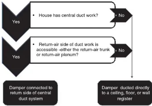
flowchart
graph TD
    A["Yes"] --> B["House has central duct work?"]
    A --> C["Return-air side of duct work is accessible -either the return-air trunk or return-air plenum?"]
    B --> D["No"]
    C --> E["No"]
    F["Damper connected to return side of central duct system"] --> G["Damper ducted directly to a ceiling, floor, or wall register"]
Outside Air Intake Location
Proper design and location of the outside air intake location is critical in ensuring that the Damper can safely and reliably provide an opening for fresh air to enter the home. The following requirements for the location of the outside air intake must be met:
- Outside air intake is located a minimum of 10' from combustion appliance vents, chimneys, plumbing stacks, and bathroom or kitchen exhaust vents. If local codes have more stringent separation requirements, they shall apply.
- Outside air intake is placed high enough above grade to prevent blockage from snow or other debris such as leaves, and at a minimum of 1' above grade.
- Make-up air damper should not draw air from crawlspaces, garages, attics, adjacent dwelling units, or any enclosed part of the building. The Damper should be installed to draw air directly from outdoors.
Outside Air Intake Opening Protection
Because the Damper, together with the end cap and outside air duct which are installed with it, will allow outdoor air into the indoor environment, it is important to meet the following requirements:
- Model 641FA (6") and 643FA (8") fresh air inlet wall caps include protective bird screens to keep out animals and outside debris. Clean screens often and do not remove.
- If a protective bird screen other than the screen provided is used, it must cover the entire opening of the outside air duct. This screen must also have openings of at least 14 " but no larger than 12 ".
- The outdoor air intake opening should meet local code provisions for the protection of openings in exterior walls, including steps to prevent moisture intrusion around the opening.
Note that the screen over the outside air opening is not a filter. It is intended to prevent the intake of leaves, animals, or debris into the outside air duct. A downstream filter is necessary to remove pollen, dust, and other airborne particles. Potential filter locations are shown below in the Typical Installations section.
Minimum Return Air Temperature Requirements
HVAC equipment manufacturers may have minimum requirements for the air temperature in the return air plenum. Introducing outdoor air to the return side of the central duct system may impact this temperature. The installer should adjust both the size of the outside air duct and the location of its connection to the return side of the central duct system in a manner so that minimum air temperature requirements are satisfied under design conditions.
WHAT IS INCLUDED IN THE PACKAGE
- Motorized Damper
- Transformer
-
Pressure Switch Kit which includes:
-
Pressure Switch
- Probe
- 12" PVC tubing 1/4" I.D.
- Gasket
- (6) Sheet Metal Screws
TOOLS REQUIRED
- 1/4" Socket Drive
- Flathead or Phillips Screw Driver
- 3/8" Drill Bit
- Duct Tape
- Low Voltage Wire (2 Conductor)
- (2) 1/4" Female Spade Terminals
- Wire Nuts
TYPICAL INSTALLATIONS
Installations will vary according to the location in the home where the unit is installed and which model Damper is used. Use the following illustrations and notes as guidance for your own installation. Always comply with local code requirements and in any instance where a detail shown below conflicts with local code, the local code provision shall apply.
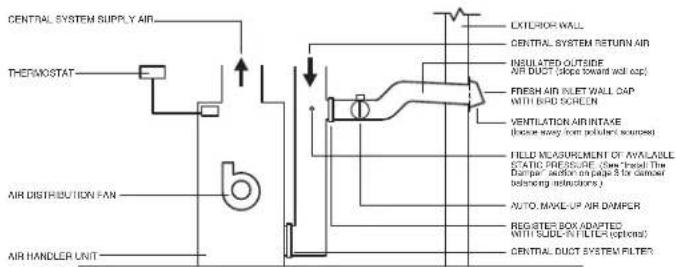
Damper connected to return side of central duct system.
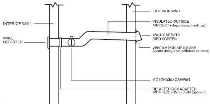
Damper and outside air duct connected directly to a ceiling, floor, or wall register.
INSTALL THE DAMPER
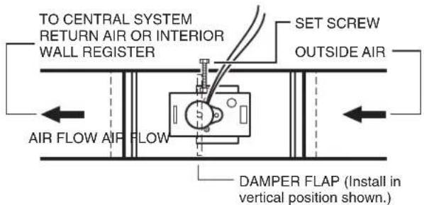
Install the damper as shown. Make sure damper flap is in a vertical position when closed and power is off. The set screw can be used to adjust the damper opening - thereby balancing the inside and outside air pressure when the range hood exhausts at high speed.
The pressure switch is designed to operate when the static pressure increases to 0.05" Ps or more. It may not operate at low speeds since the pressure is below this limit.
MULTIPLE DAMPERS
More than one damper may be required to balance the system. If more than one is required use (1) MD6TU or MD8TU and then use the MD6 or MD8 dampers as additional dampers.
INSTALLATION OF PRESSURE SWITCH AND PROBE
For the probe & pressure switch to work effectively the roof or wall cap must have a spring loaded damper. The following Broan products are recommended:
Roof Cap models:
437 - High capacity up to
1200 cfm
634 / 644 - For 3 14 x 10" and
up to 8" round
634M – For 6" round
Wall Cap models:
WC638 - For 3¼" x 14" duct
639 / 649 - For 3 14 x 10" duct
647 - For 7" round duct
843BL / 641 - For 6" round duct
643 / 643FA – For 8" round duct
613 - For 12" round duct
441 - For 10" round duct.
LOCATION OF PROBE AND PRESSURE SWITCH
The probe must be mounted between the range hood damper and the wall cap, roof cap, in-line blower or external blower. Mount the probe as close to the hood outlet as possible but make sure the hood damper operation is not affected.
The pressure switch should be mounted so it is accessible for any future service. The switch can mounted no more than 72" away from the probe. If longer tubing is required then what is supplied, purchase 1/4" I.D. PVC tubing from a local source. See the illustrations below for possible installation scenarios.
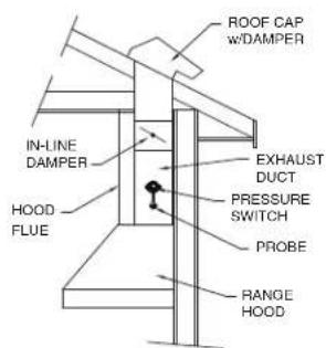
TYPICAL INSTALLATION WITH INTERNAL BLOWER AND ROOF VENT
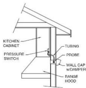
TYPICAL INSTALLATION WITH INTERNAL BLOWER AND HORIZONTAL DUCTING w/ WALL VENT
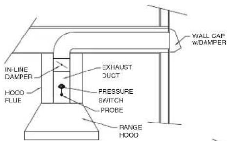
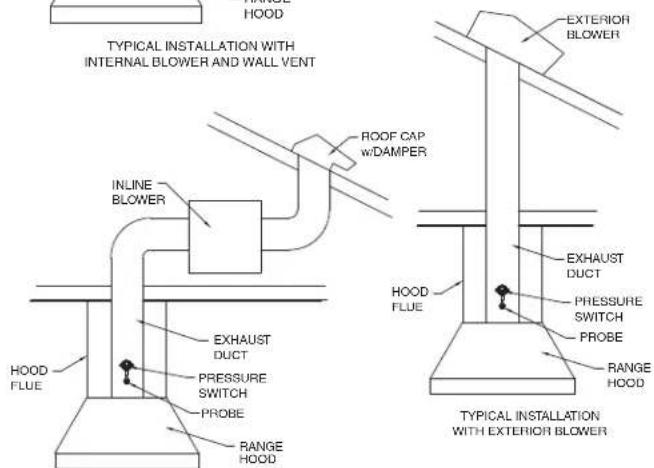
TYPICAL INSTALLATION WITH INLINE BLOWER
MOUNTING POSITIONS OF PROBE & PRESSURE SWITCH
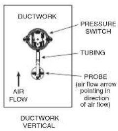
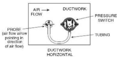
MOUNT THE PROBE & PRESSURE SWITCH
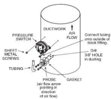
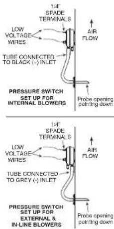
WIRE THE SYSTEM
Wire the system as shown.
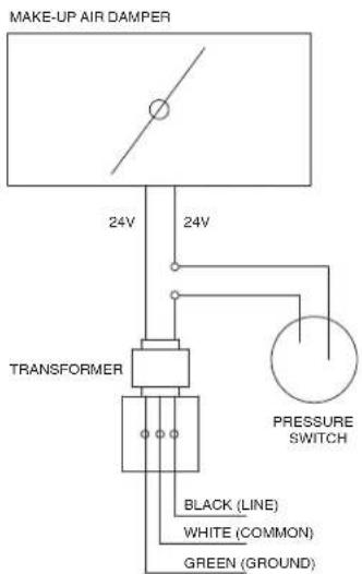
WIRING DIAGRAM ONE DAMPER
WIRE THE SYSTEM (Continued)
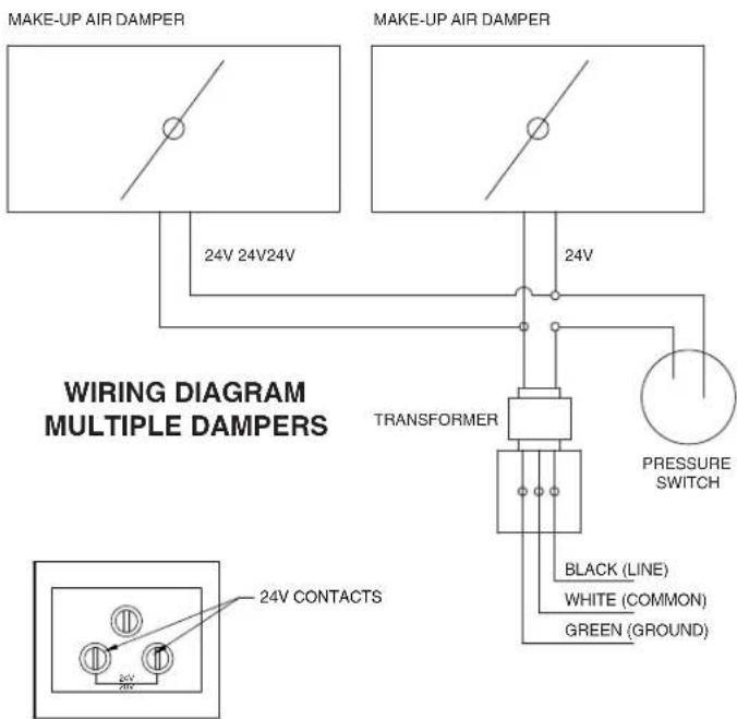
TRANSFORMER WIRING
TEST THE SYSTEM
Once the damper, pressure switch, and probe is installed. Turn on the range hood to high speed and confirm that the damper opens. Turn off the hood and check to see if the damper closes.
A qualified HVAC contractor should also ensure the proper operation and venting of all combustion equipment in the home.
FALSE TRIPPING
Under certain extreme conditions there could be false tripping of the damper (opening when the range hood blower is off). If false tripping is encountered, place an in-line backdraft damper (7" model no. 97, 8" model no. 438, 10" model no. 421) between the probe and the roof or wall cap.
SERVICE PARTS
97018853 Pressure Switch Kit
97013273 24V Transformer
99527207 6" Motorized Damper
99527208 8" Motorized Damper
99528460 10" Motorized Damper
MAINTENANCE
Regular maintenance is necessary to ensure the proper operation of the Damper system. Failure to conduct such routine maintenance can jeopardize the ability of the Damper to introduce fresh air into the home. Regular maintenance should include the following activities:
- Clean the outside bird screen to ensure it is free from debris and open to allow fresh air to enter.
- Clean or replace the interior filter(s) which serve to filter fresh air before it enters the home.
- Maintain a clear opening at the outdoor end cap, which means preventing the buildup of snow, leaves, or vegetation at the end cap.
- During regular HVAC maintenance, have the mechanical contractor inspect the Damper system for proper operation.
1. What does the Broan Automatic Make-Up Air Damper do?
The Broan Automatic Make-Up Air Damper (the "Damper") provides a pathway for fresh air to enter a home from outdoors when a compatible exhaust device is operating. The Damper opens when a compatible BEST, Broan Elite or Broan range hood is operating, thereby creating a known, controlled point for fresh air to enter the home while air is being exhausted from the building by the range hood.
By operating in this manner, the Damper provides two key benefits for the home:
- It facilitates air exchange between indoors and outdoors, by helping to allow fresh air into the home to replace air which is exhausted out of the home.
- By allowing fresh air into the building when a compatible exhaust device is on, the Damper helps to avoid negative pressure conditions within the home which may interfere with the proper operation of combustion equipment within the home.
Overall, the Damper let's your BEST, Broan Elite or Broan exhaust devices do their job more effectively and without interfering with the proper operation of other home systems.
2. Does the "Damper" provide combustion air for combustion appliances like a water heater or a furnace?
No. The Damper helps to replace air which is exhausted by a compatible range hood. But it does NOT help to replace air which is drawn from the indoors by a combustion appliance like a natural gas water heater, and it should not be relied upon to perform this function. One main reason for this restriction is that the Damper is only open when the range hood that it's connected to is operating. So there is no assurance that the Damper would be open when other appliances, like a water heater, are operating. Other means must be provided to ensure adequate combustion air for these appliances.
3. How do I know if I need make-up air for my range hood?
In some cases the local building code may tell you that make-up air is necessary. For example, some codes specify that range hoods with exhaust flows of 300 cubic feet per minute (CFM) or higher need a mechanical system to introduce make-up air.
In other cases, make-up air for a range hood is desirable regardless of whether code requires it. This is especially true for:
• larger range hoods (those over 300 cfm)
- homes which are well air-sealed - so outside air may not be able to easily find its way into the home through cracks, to replace air which is exhausted out
- homes with atmospherically vented combustion appliances (i.e. a water heater or natural draft fireplace), which are more susceptible to improper venting if depressurization occurs in the home.
In homes with any one of these factors make-up air is advised. And in homes with more than one of these conditions make-up air for the range hood is strongly advised.
4. What are the benefits of providing make-up air to replace air which is exhausted out of the home by a range hood?
Range hoods are designed to pull out pollutants like cooking odors or moisture at the source, so they don't linger in the home. Because these fans pull air out of the house, this air needs to be replaced with "new" air from outdoors. Normally this make-up air enters the home through cracks and holes in the "shell" of the building. But modern homes are air-sealed much more thoroughly so there are not as many cracks and openings. Plus some exhaust fans like range hoods exhaust a lot more air than can be replaced through normal cracks in the building shell.
By providing an intentionally designed opening for fresh air to replace air which is exhausted out by the range hood, several important benefits result:
- The make-up air entering the home comes in at a known point, where it is also filtered
- Negative pressure conditions, which could arise if air is exhausted from a home without being replaced by new fresh air, are prevented
- Pollutants are more effectively exhausted from the home while fresh replacement air is drawn into the home, improving ventilation
5. Does ASHRAE 62.2-2007 – “Ventilation and Acceptable Indoor Air Quality in Low-Rise Residential Buildings” – require the use of a make-up air damper?
ASHRAE 62.2-2007 does not specifically require make-up air dampers. In a few limited circumstances, this standard does require that net exhaust flows from a house be limited. For example, Section 6.4 of the standard limits the net exhaust flow from a home's two largest exhaust appliances if the home has atmospherically vented or solid-fuel burning appliances located within the pressure boundary of the house. This standard is available at www.ashrae.org.
6. Can I use the Broan Automatic Make-Up Air Damper with other equipment in my home?
No. The Broan Automatic Make-Up Air Damper may only be used with compatible BEST, Broan Elite or Broan range hoods. More information on exact models of the Damper and compatible exhaust devices can be found in the Broan Automatic Make-Up Air Damper Application Guide.
7. What are the different ways that the Damper can be installed in my home?
The most common way to install the Damper is to connect it to a home's central duct system. In this application, outside fresh air enters the home through the Damper and is then routed and distributed through the home's ducts. More information on this installation approach can be found in the Broan Automatic Make-Up Air Damper Application Guide on our web site: www.broan.com.
8. What if my home doesn't have ducts?
Homes without ducts can still utilize the Damper to help replace air which is exhausted from the home by the range hood. An installation illustration for this situation is included in the Broan Automatic Make-Up Air Damper Application Guide on our web site: www.broan.com.
9. What happens after a power outage?
The Damper system and the associated exhaust devices will not lose their settings following a power outage. So the system will resume its normal operation following a power outage, based on the settings it used prior to the outage.
CLAPET AUTOMATIQUE D'AIR DE COMPENSATION AVEC TRANSFORMATEUR ET MANOCONTACTEUR
Broan, 926 W. State Street, Hartford, WI 53027 800-637-1453
LIRE CES DIRECTIVES ET LES CONSERVER

POUR USAGE RÉSIDENTIEL SEULEMENT

AVERTISSEMENT


OBSERVEZ LES DIRECTIVES CI-DESSOUS AFIN DE RÉDUIRE LES RISQUES D'INCENDIE, DE CHOC ELECTRIQUE OU DE BLESSURES CORPORELLES :
Broan, 926 W. State Street, Hartford, WI 53027 800-637-1453
LEA Y CONSERVE ESTAS INSTRUCCIONES
SOLO PARA USO RESIDENCIAL
ADVERTENCIA

PARA REDUCIR EL RIESGO DE INCENDIOS, DESCARGAS ELÉCTRICAS O LESIONES PERSONALES, SIGA LAS SIGUIENTES PRECAUCIONES:

- AUTOMATIC MAKE-UP AIR DAMPER WITH TRANSFORMER & PRESSURE SWITCH
- READ AND SAVE THESE INSTRUCTIONS
- CAUTION
- PLAN THE INSTALLATION
- Outside Air Intake Location
- Outside Air Intake Opening Protection
- Minimum Return Air Temperature Requirements
- WHAT IS INCLUDED IN THE PACKAGE
- TOOLS REQUIRED
- TYPICAL INSTALLATIONS
- INSTALL THE DAMPER
- MULTIPLE DAMPERS
- INSTALLATION OF PRESSURE SWITCH AND PROBE
- Roof Cap models:
- Wall Cap models:
- LOCATION OF PROBE AND PRESSURE SWITCH
- MOUNTING POSITIONS OF PROBE & PRESSURE SWITCH
- MOUNT THE PROBE & PRESSURE SWITCH
- WIRE THE SYSTEM
- WIRE THE SYSTEM (Continued)
- TEST THE SYSTEM
- FALSE TRIPPING
- SERVICE PARTS
- MAINTENANCE
- What does the Broan Automatic Make-Up Air Damper do?
- Does the "Damper" provide combustion air for combustion appliances like a water heater or a furnace?
- How do I know if I need make-up air for my range hood?
- What are the benefits of providing make-up air to replace air which is exhausted out of the home by a range hood?
- Does ASHRAE 62.2-2007 – “Ventilation and Acceptable Indoor Air Quality in Low-Rise Residential Buildings” – require the use of a make-up air damper?
- Can I use the Broan Automatic Make-Up Air Damper with other equipment in my home?
- What are the different ways that the Damper can be installed in my home?
- What if my home doesn't have ducts?
- What happens after a power outage?
- CLAPET AUTOMATIQUE D'AIR DE COMPENSATION AVEC TRANSFORMATEUR ET MANOCONTACTEUR
- LIRE CES DIRECTIVES ET LES CONSERVER
- POUR USAGE RÉSIDENTIEL SEULEMENT
- AVERTISSEMENT
- OBSERVEZ LES DIRECTIVES CI-DESSOUS AFIN DE RÉDUIRE LES RISQUES D'INCENDIE, DE CHOC ELECTRIQUE OU DE BLESSURES CORPORELLES :
- LEA Y CONSERVE ESTAS INSTRUCCIONES
- SOLO PARA USO RESIDENCIAL
- ADVERTENCIA
- PARA REDUCIR EL RIESGO DE INCENDIOS, DESCARGAS ELÉCTRICAS O LESIONES PERSONALES, SIGA LAS SIGUIENTES PRECAUCIONES:
Brand : BEST
Model : MD8TU
Category : Ventilation system