P2 Auto - Welding machine GYS - Free user manual and instructions
Find the device manual for free P2 Auto GYS in PDF.

User questions about P2 Auto GYS
0 question about this device. Answer the ones you know or ask your own.
Ask a new question about this device
Download the instructions for your Welding machine in PDF format for free! Find your manual P2 Auto - GYS and take your electronic device back in hand. On this page are published all the documents necessary for the use of your device. P2 Auto by GYS.
USER MANUAL P2 Auto GYS
natural_image
Line drawings of three industrial electrical control cabinets with wheels and control panels (no text or symbols)| FR | 2 - 4 / 5 - 19 / 78 - 88 |
| UK | 2 - 4 / 20 - 28 / 78 - 88 |
| DE | 2 - 4 / 29 - 38 / 78 - 88 |
| ES | 2 - 4 / 39 - 47 / 78 - 88 |
| RU | 2 - 4 / 48 - 57 / 78 - 88 |
| NL | 2 - 4 / 58 - 67 / 78 - 88 |
| IT | 2 - 4 / 68 - 77 / 78 - 88 |
P1 / P2 / P3 GYS AUTO
Générateur MIG/MAG MIG/MAG - welding machine Schweissgerät für MIG/MAG Equipo de soldadura MIG/MAG Сварочный аппарат МИГ/МАГ MIG/MAG lasapparaat Dispositivo saldatura MIG/MAG
P1 GYS AUTO
P2 GYS AUTO
P3 GYS AUTO
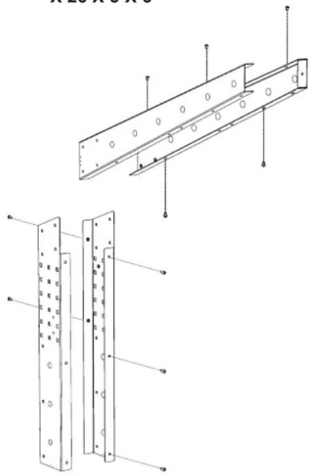
POTENCE SEULE / BALANCING ARM ONLY / AUSLEGER / SOPORTE SOLO / КРОНШТЕЙН / STEUN ALLEEN / BRACCIO DI SOSTEGNO SINGOLO | 077300
M6X12 M6X40 M6


X 26 X 3 X 3
natural_image
Technical line drawing of a structural panel assembly with mounting holes and mounting holes (no text or symbols)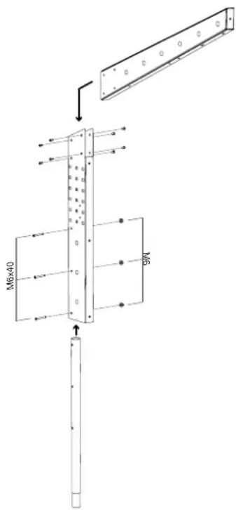
text_image
M6×40 MP4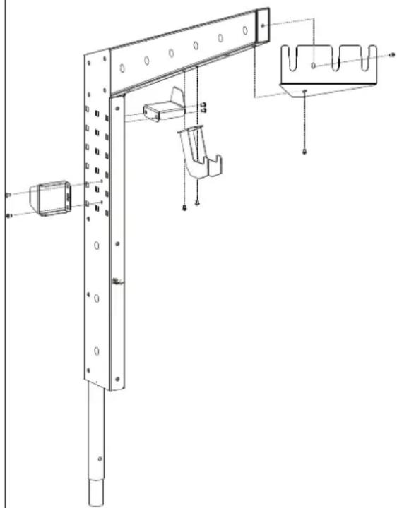
natural_image
Technical line drawing of a mechanical bracket assembly with mounting holes and support components (no text or symbols)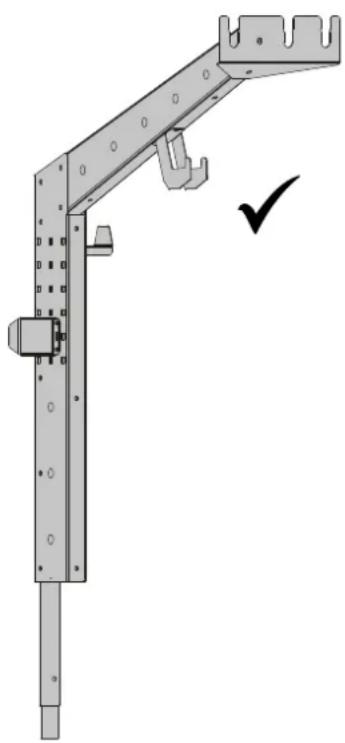
natural_image
Mechanical bracket assembly diagram with no visible text or symbols
natural_image
Technical line drawing of a mechanical assembly with three views showing structural components (no text or symbols)SUPPORT BOUTEILLE / BOTTLE SUPPORT / FLASCHENHALTER / PORTABOTELLAS / FLESSENHOU-DER / PORTABOTTIGLIE
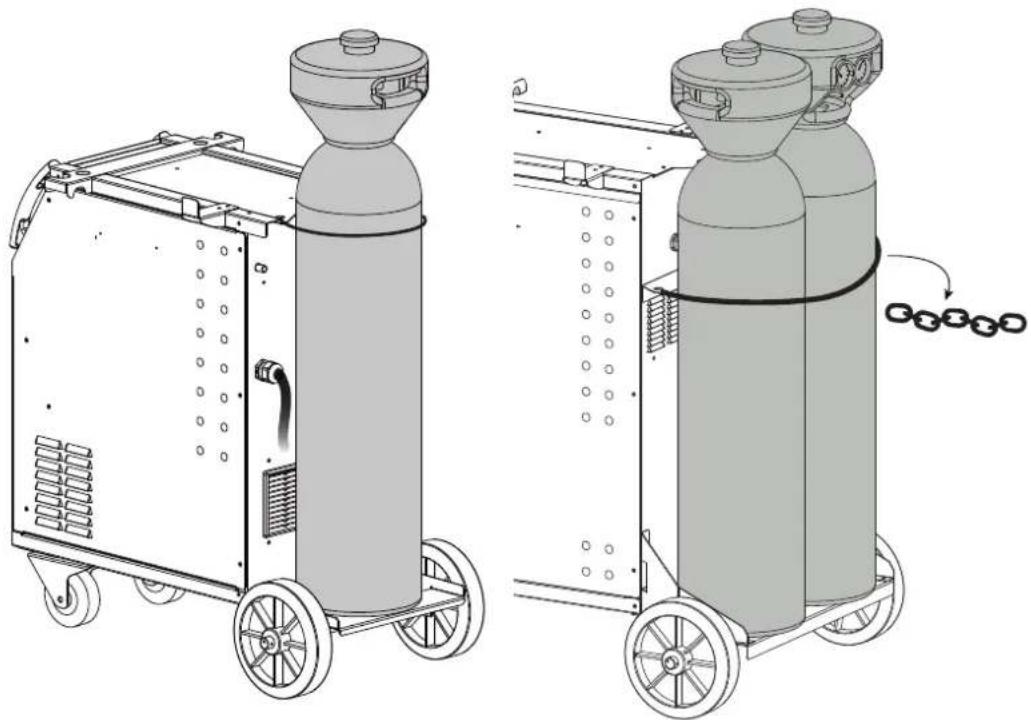
natural_image
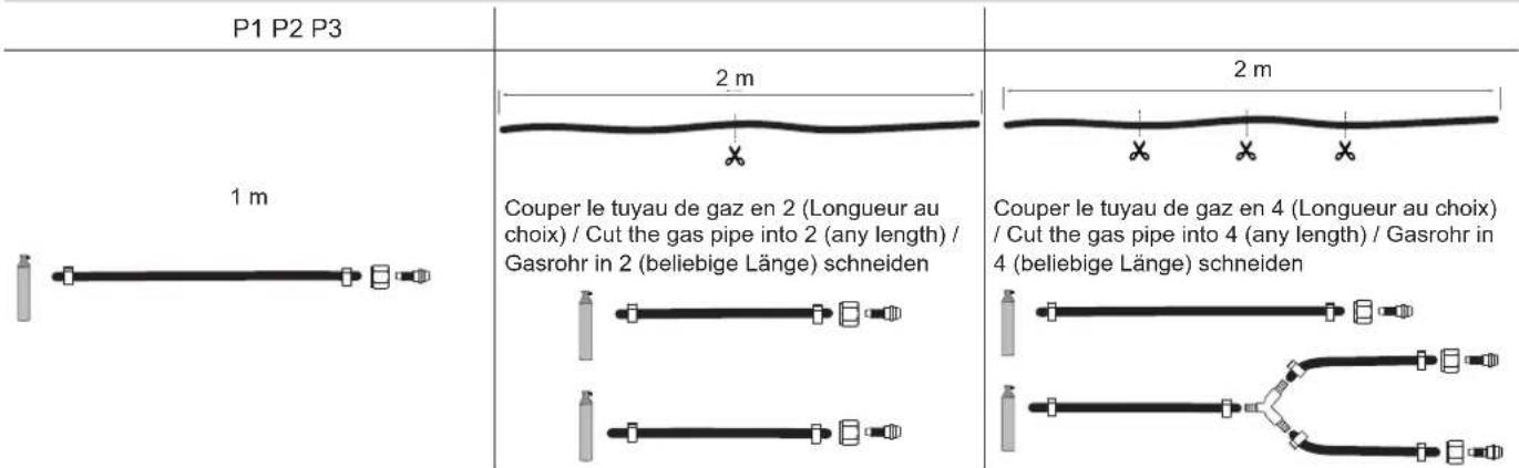
Technical line drawings of two cylindrical industrial machines with wheels, showing internal components and a rotation arrow (no text or symbols)P1 GYS AUTO 4 m³ max P2 et P3 GYS AUTO 2 x 4 m
^3 max
PROCÉDURE DE MISE À JOUR / UPDATE PROCEDURE
Clé USB non fournie / USB key not included.
| 1 | 2 | |
| STOP | ||
| 345 | ||
| START | System Update - V1.02 Please Wait ... Auto-Full-202 Full.egf Check File Integrity | |
RACCORD GAZ / GAS FITTINGS / GASANSCHLUSS / CONEXIÓN DE GAS / ГАЗОВОЕ СОЕДИНЕНИЕ / GAS AANSLUITING / COLLEGAMENTO GAS
text_image
Technical diagram of a mechanical device with numbered components for identification and assembly reference.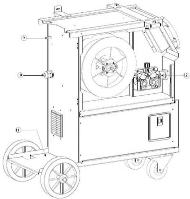
text_image
Technical diagram of a mechanical device with numbered components for identificationP2
text_image
Technical diagram of a mechanical device with numbered components and labeled parts, likely for assembly or maintenance reference.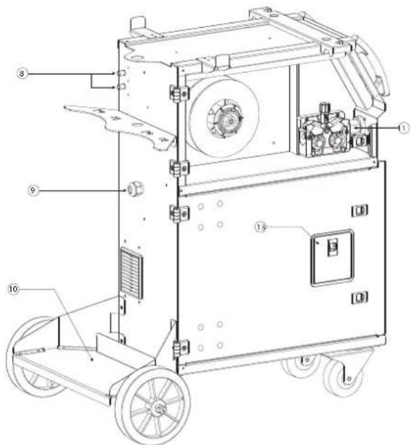
text_image
Technical diagram of a mechanical device with numbered components for identificationP3
text_image
Technical diagram of a mechanical device with numbered components for identification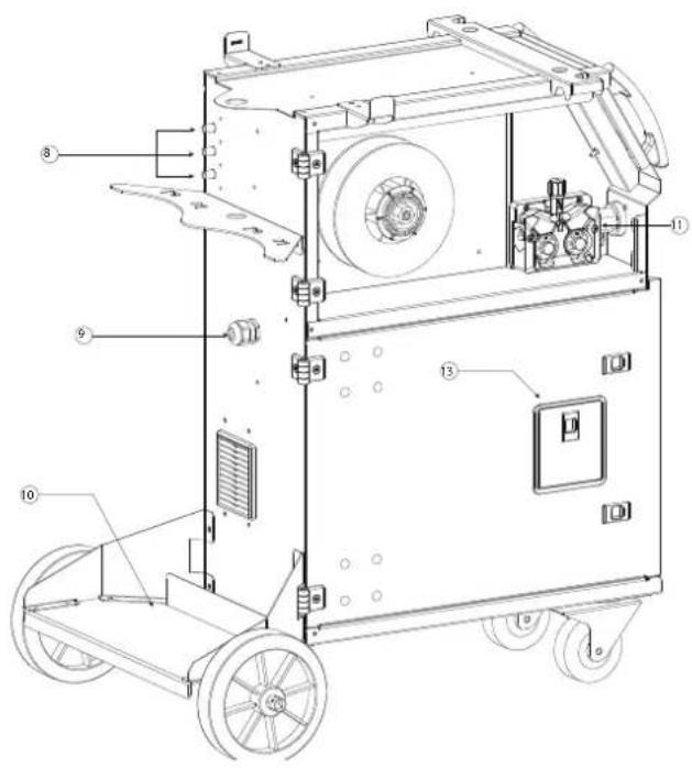
text_image
Technical diagram of a mechanical device with numbered components for identificationAVERTISSEMENTS - RÈGLES DE SÉCURITÉ
CONSIGNE GÉNÉRALE
INSTALLATION - FONCTIONNEMENT PRODUIT
INTERFACE HOMME-MACHINE (IHM)

natural_image
Technical line drawing of a mechanical assembly with labeled parts (a and b), no readable text or symbols present.natural_image
Pure diagram of a vertical cylindrical structure with directional arrows indicating flow or movement (no text or symbols)natural_image
Technical line drawing of a mechanical component with no visible text or symbolsANOMALIES, CAUSES, REMÈDES
CONDITIONS DE GARANTIE
These instructions must be read and understood before any operation.
Any modification or maintenance not indicated in the manual must not be undertaken.
The manufacturer will not be held responsible for any damage to persons or property resulting from use which does not comply with the instructions in this manual.
In the event of any problem or uncertainty, please consult a qualified person in order to handle the installation correctly.
ENVIRONMENT
This equipment must only be used for welding operations within the limits indicated on the nameplate and/or in the manual. Safety instructions must be observed. In the event of inappropriate or dangerous use, the manufacturer cannot be held responsible.
The installation must be used in a room free from dust, acids, flammable gases or other corrosive substances. The same applies to storage. Ensure air circulation during use.
Temperature range:
Use between -10 and +40°C (+14 and +104°F).
Storage between -20 and +55°C (-4 and 131°F).
Air humidity:
Less than or equal to 50% at 40°C (104°F).
Less than or equal to 90% at 20°C (68°F).
Altitude:
Up to 1000m above sea level (3280 feet)
PERSONAL AND PERSONAL PROTECTION INDIVIDUAL AND OTHER
Arc welding can be dangerous and cause serious or even fatal injuries.
Welding exposes people to a dangerous source of heat, radiation from the arc, electromagnetic fields (beware of pacemaker wearers), risk of electrocution, noise and gaseous fumes.
To protect yourself and others, observe the following safety instructions:

To protect yourself from burns and radiation, wear clothing that is cuffless, insulating, dry, fireproof and in good condition, and that covers the whole body.

Use gloves that guarantee electrical and thermal insulation.

Use welding protection and/or a welding bonnet with a sufficient level of protection (depending on the application). Protect your eyes during cleaning operations. Contact lenses in particular are not recommended.
It is sometimes necessary to delimit areas with fireproof curtains to protect the welding zone from the rays of the arc, projections and incandescent waste.
Inform people in the welding zone not to stare at the rays of the arc or molten parts and to wear appropriate clothing to protect themselves.

Use noise-cancelling headphones if the welding process produces a noise level in excess of the authorised limit (the same applies to anyone in the welding area).
Keep hands, hair and clothing away from moving parts (fan).
Never remove the cooling unit housing protectors when the welding current source is live, as the manufacturer cannot be held responsible in the event of an accident.
Parts that have just been welded are hot and can cause burns when handled. When servicing the torch or electrode holder, ensure that it is sufficiently cold by waiting at least 10 minutes before servicing. The cooling unit must be switched on when using a water-cooled torch to ensure that the liquid cannot cause burns.
It is important to secure the work area before leaving it in order to protect people and property.
WELDING FUMES AND GASES

The fumes, gases and dusts emitted by welding are hazardous to health. Sufficient ventilation must be provided, and an air supply is sometimes necessary. A fresh-air mask can be a solution if ventilation is inadequate.
Check that the extraction system is effective by checking it against safety standards.
Warning: welding in small spaces requires supervision from a safe distance. In addition, soldering certain materials containing lead, cadmium, zinc or mercury, or even beryllium, can be particularly harmful.
Cylinders must be stored in open or well-ventilated premises. They should be in an upright position and held on a support or trolley.
Welding should not be carried out near grease or paint.
RISK OF FIRE AND EXPLOSION

Fully protect the welding area; flammable materials must be at least 11 metres away. Fire-fighting equipment must be available in the vicinity of welding operations.
Beware of hot material or sparks, as even through cracks they can be a source of fire or explosion.
Keep people, flammable objects and pressurised containers at a safe distance.
Do not weld in closed containers or tubes, and if they are open, empty them of all flammable or explosive materials (oil, fuel, gas residues, etc.).
Do not grind in the direction of the welding current source or flammable materials.
GAS CYLINDERS

The gas coming out of the cylinders can be a source of suffocation if concentrated in the welding area (ventilate well).
Cylinders must be transported in complete safety, with the cylinders closed and the welding current source switched off. They must be stored vertically and held by a support to limit the risk of falling.
Close the cylinder between uses. Beware of temperature variations and exposure to sunlight.
The cylinder must not come into contact with a flame, electric arc, torch, earth clamp or any other source of heat or incandescence.
Keep away from electrical and welding circuits and never weld a cylinder under pressure.
When opening the cylinder valve, keep the head away from the fittings and ensure that the gas used is suitable for the welding process.
ELECTRICAL SAFETY

The electrical network used must be earthed. Use the fuse size recommended on the rating plate.
An electric shock can be a source of serious direct or indirect accident, or even death.
Never touch live parts inside or outside the live current source (torches, clamps, cables, electrodes) as these are connected to the welding circuit.
Before opening the welding current source, disconnect it from the mains and wait 2 minutes. so that all the capacitors are discharged.
Do not touch the torch or electrode holder and the earth clamp at the same time.
If the cables or torches are damaged, they should be replaced by qualified and authorised personnel. Size the cable cross-section to suit the application. Always use dry clothing in good condition to insulate yourself from the welding circuit. Wear insulating footwear in all working environments.
CEM CLASSIFICATION OF EQUIPMENT

This Class A equipment is not intended for use in a residential site where the electrical current is supplied by the public low-voltage supply network. There may be potential difficulties in ensuring electromagnetic compatibility in such sites, due to conducted, as well as radiated, radio frequency interference.
Provided that the impedance of the public low voltage supply network at the point of common coupling is less than Zmax = 0.450 Ohms, this equipment complies with IEC 61000-3-11 and may be connected to the public low voltage supply networks. It is the responsibility of the installer or user of the equipment to ensure, by consulting the distribution network operator if necessary, that the network impedance complies with the impedance restrictions.
This equipment complies with IEC 61000-3-12.
ELECTRO-MAGNETICS
Electric current passing through any conductor produces localised electric and magnetic fields (EMF). Welding current produces an electromagnetic field around the welding circuit and welding equipment.
Electromagnetic EMF fields can interfere with certain medical implants, such as pacemakers. Protective measures must be taken for people with medical implants. For example, access restrictions for bystanders or an individual risk assessment for welders.
All welders should use the following procedures to minimise exposure to electromagnetic fields from the welding circuit:
- position the welding cables together - secure them with a clamp, if possible;
•position themselves (torso and head) as far away from the welding circuit as possible; - never wrap the welding cables around the body;
•do not position the body between the welding cables. Hold both welding cables on the same side of the body; - connect the return cable to the workpiece as close as possible to the area to be welded;
- do not work next to the welding power source, do not sit on it or lean against it;
- do not weld when transporting the welding power source or the wire feeder.

Pacemaker wearers should consult a physician before using this equipment.
Exposure to electromagnetic fields during welding may have other health effects that are not yet known.
RECOMMENDATIONS FOR ASSESSING THE WELDING AREA AND INSTALLATION
General
The user is responsible for installing and using the arc welding equipment in accordance with the manufacturer's instructions. If electromagnetic interference is detected, it must be the responsibility of the user of the arc welding equipment to resolve the situation with the manufacturer's technical assistance. In some cases, this corrective action may be as simple as earthing the welding circuit. In other cases, it may be necessary to construct an electromagnetic shield around the welding current source and the entire workpiece, with input filters fitted. In all cases, electromagnetic interference should be reduced until it is no longer a nuisance.
Assessment of the welding area
Before installing any arc welding equipment, the user should assess the potential electromagnetic problems in the surrounding area. The following should be considered:
a) the presence above, below and adjacent to the arc welding equipment of other power, control, signalling and telephone cables;
b) radio and television receivers and transmitters;
c) computers and other control equipment;
d) safety-critical equipment, e.g. protection of industrial equipment;
e) the health of neighbouring persons, e.g. use of pacemakers or hearing aids;
f) equipment used for calibration or measurement;
g) the immunity of other equipment in the environment.
The user must ensure that other equipment used in the environment is compatible. This may require additional protective measures;
h) the time of day when welding or other activities are to be carried out.
The size of the surrounding area to be taken into account depends on the structure of the building and other activities taking place within it. The surrounding area may extend beyond the boundaries of the facilities.
Welding facility assessment
In addition to the area assessment, the arc welding facility assessment can be used to identify and resolve cases of disturbance. The assessment of emissions should include in situ measurements as specified in Article 10 of CISPR 11. In situ measurements can also be used to confirm the effectiveness of mitigation measures.
RECOMMENDATIONS ON METHODS OF REDUCING ELECTROMAGNETIC EMISSIONS
a. Public mains supply: Arc welding equipment should be connected to the public mains supply in accordance with the manufacturer's recommendations. If interference occurs, it may be necessary to take additional preventive measures such as filtering the public power supply. It is advisable to envisage shielding of the supply cable in metal conduit or equivalent from permanently installed arc welding equipment. The electrical continuity of the shielding must be ensured along its entire length. The shield should be connected to the welding power source to ensure good electrical contact between the conduit and the enclosure of the welding power source.
b. Maintenance of arc welding equipment: Arc welding equipment should be subject to routine maintenance in accordance with the manufacturer's recommendations. All accesses, service doors and covers should be closed and properly locked when the arc welding equipment is in use. Arc welding equipment should not be modified in any way other than those modifications and adjustments specified in the manufacturer's instructions. In particular, the arc splitter of arc starting and stabilising devices should be adjusted and maintained in accordance with the manufacturer's recommendations.
c. Welding cables: Cables should be as short as possible, laid close together near the floor or on the floor.
d. Equipotential bonding: Consideration should be given to bonding all metal objects in the surrounding area. However, metal objects connected to the part to be welded increase the risk of electric shock to the operator if he touches both these metal elements and the electrode. The operator should be isolated from such metal objects.
e. Earthing the workpiece: Where the workpiece to be welded is not earthed for electrical safety or because of its size and location, for example ship hulls or structural steel in buildings, an earthed connection to the workpiece may, in some but not all cases, reduce emissions. Care should be taken to avoid earthing parts which could increase the risk of injury to users or damage to other electrical equipment. If necessary, the connection of the part to be welded to earth should be made directly, but in some countries where this direct connection is not permitted, the connection should be made with an appropriate capacitor chosen in accordance with national regulations.
f. Protection and shielding: Selective protection and shielding of other cables and equipment in the surrounding area can limit interference problems. Protection of the entire welding area may be considered for special applications.
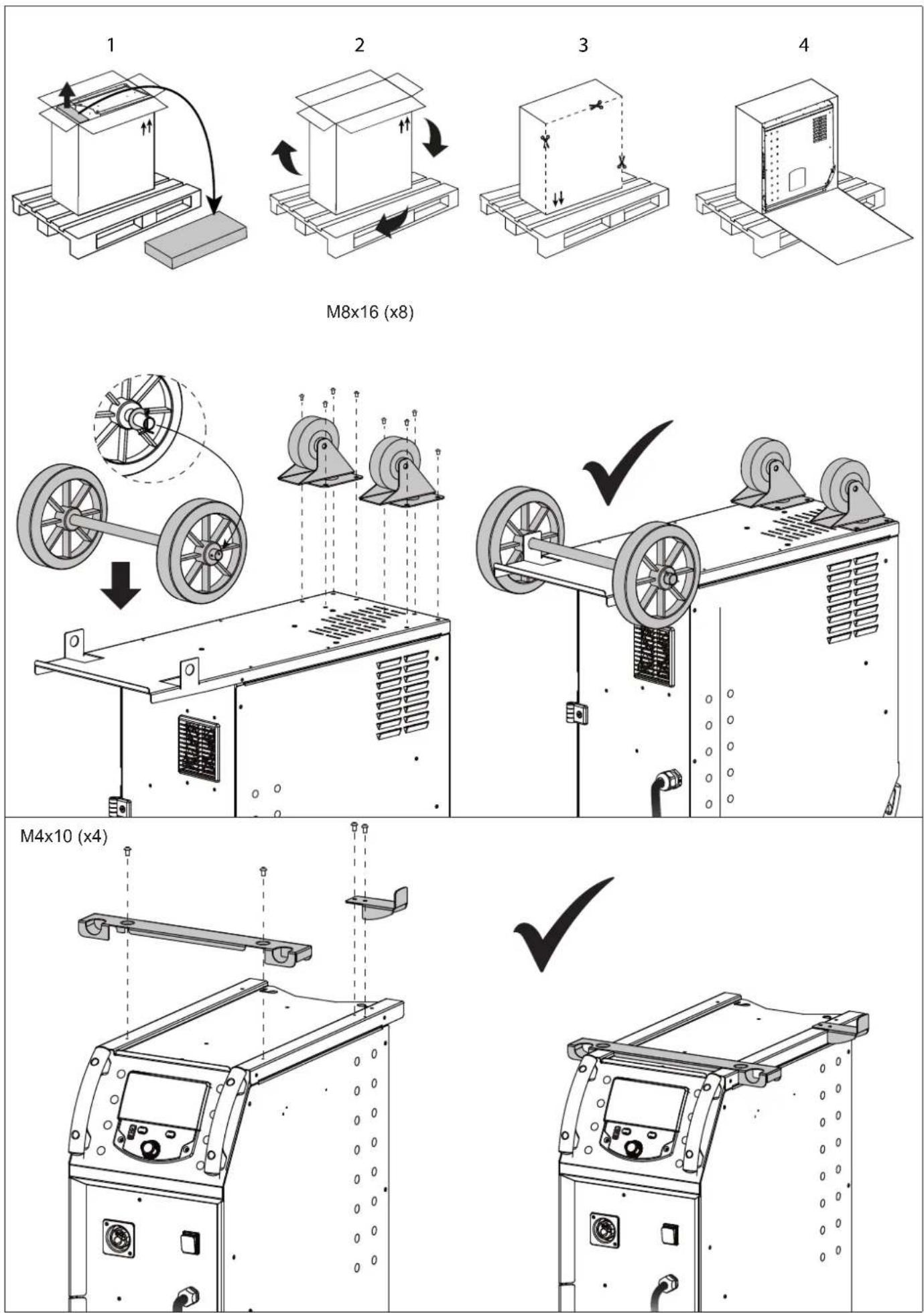
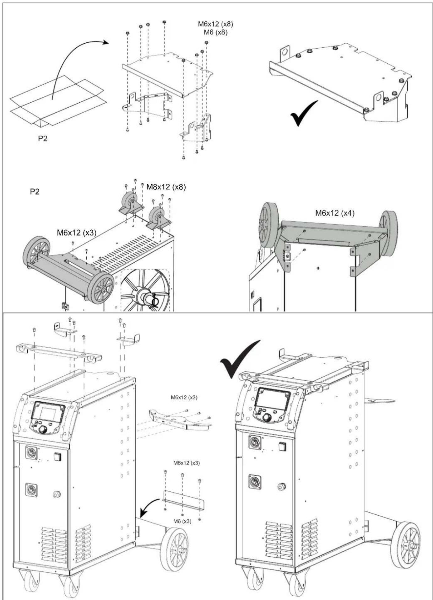
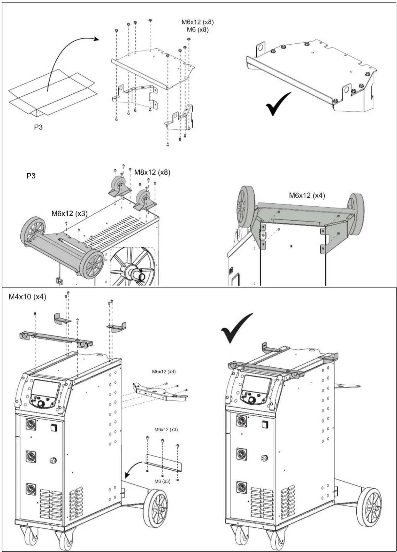
TRANSPORT AND TRANSIT OF WELDING CURRENT SOURCE

Do not use the cables or torch to move the welding current source. It must be moved in a vertical position. Do not run the current source over people or objects.
Never lift a gas cylinder and the welding current source at the same time. Their transport standards are different. It is preferable to remove the wire spool before lifting or transporting the welding power source.
INSTALLATION OF EQUIPMENT
- Place the welding power source on a floor with a maximum gradient of 10^ .
- Provide sufficient space to ventilate the welding power source and access the controls.
- Do not use in an environment containing conductive metal dust.
- The welding power source must be protected from driving rain and must not be exposed to direct sunlight.
•The equipment has an IP23S degree of protection, meaning: - protection against access to dangerous parts of solid bodies with a diameter >12.5 mm and,
- protection against rain directed at 60° to the vertical when its moving parts (fan) are stationary.
This equipment can therefore be stored outdoors in accordance with the IP23S degree of protection.
Stray welding currents can destroy earth conductors, damage electrical equipment and devices and cause components to overheat, leading to fire.
- All welding connections must be firmly connected and checked regularly!
- Ensure that the workpiece is securely fastened and free from electrical problems!
- Attach or suspend all electrically conductive parts of the welding source such as the chassis, trolley and lifting systems so that they are insulated!
- Do not place other equipment such as drills, grinding devices, etc. on the welding source, trolley or lifting systems unless they are insulated!
- Always place welding torches or electrode holders on an insulated surface when not in use!
Power supply, extension and welding cables must be completely unwound to avoid overheating.

The manufacturer accepts no responsibility for damage to persons or property caused by incorrect and dangerous use of this equipment.
- Maintenance must only be carried out by a qualified person. Annual maintenance is recommended.
- Switch off the power supply by pulling the plug and wait two minutes before working on the equipment. The voltages and currents inside are high and dangerous.
•Regularly remove the cover and blow off the dust. Take the opportunity to have the electrical connections checked with an insulated tool by qualified personnel.
- Regularly check the condition of the power cord. If the power cable is damaged, it must be replaced by the manufacturer, its after-sales service or a similarly qualified person, to avoid any danger.
- Leave the welding power source vents free for air intake and exhaust.
- Do not use this welding current source to defrost pipes, recharge batteries/accumulators or start motors.
INSTALLATION - OPERATION PRODUCT
Only experienced personnel authorised by the manufacturer may carry out the installation. During installation, make sure that the generator is disconnected from the mains. Do not connect the generator in series or in parallel. It is recommended to use the welding cables supplied with the equipment in order to obtain optimum product settings.
DESCRIPTION
This equipment is a single-phase power source for semi-automatic "synergic" welding (MIG or MAG). The P1 GYS AUTO accepts ∅ 200 and 300 mm wire reels. The P3 accepts ∅ 200 wire reels.
DESCRIPTION OF EQUIPMENT (II)
P1
1- Reel support ∅ 200/300 mm 9- Gas connector
2- Accessory box hatch 10- Mains connection
3- Cable support 11-4m
4- Torch support 12- Motor hose reel
5- HMI (Human Machine Interface) 13- USB connection
6- START/STOP switch
7- Ground cable (-) 3.5 m
8- Euro connector (torch x1)
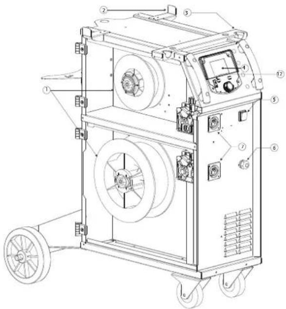
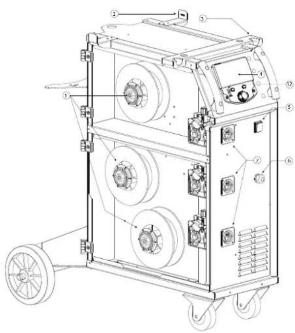
P2
1- Reel support ∅ 200/300 mm 8- Gas connector
2- Cable support 9- Mains connection
3- Torch support 10- bottle support 2x4m
4- HMI (Human Machine Interface) 11- Motor hose reel
5- START/STOP switch 12- USB connection
6- Ground cable (-) 3.5 m 13- Accessory box hatch
7- Euro connector (torch x2)
P3
1- Reel support ∅ 200 mm 8- Gas connector
2- Cable support 9- Mains connection
3- Torch support 10- bottle support 2x4m
4- HMI (Human Machine Interface) 11- Motor hose reel
5- START/STOP switch 12- USB connection
6- Ground cable (-) 3.5 m 13- Accessory box hatch
7- Euro connector (torch x3)
^3 bottle support
3
3
HUMAN MACHINE INTERFACE (HMI)

HMI
Please read the user manual for the interface (HMI), which is part of the complete equipment documentation.
POWER SUPPLY-START-UP
- The 230 V model is supplied with a 16 A CEE7/7 type plug and must only be used on a 230 V (50 - 60 Hz) single-phase, three-wire electrical installation with an earthed neutral conductor.
•The 208/240 V model is supplied without a plug and must only be used on a single-phase 208-240 V (50-60 Hz) three-wire electrical installation with an earthed neutral conductor.
The effective absorbed current (I1eff) is indicated on the appliance for maximum operating conditions. Check that the power supply and its protection (fuse and/or circuit breaker) are compatible with the current required during use. In some countries, it may be necessary to change the plug to enable use under maximum conditions. - The power source is designed to operate on an electrical voltage of 230V - 20% +15% . It goes into protection if the supply voltage is less than 185 Vrms or more than 265 Vrms (a fault code will appear on the display).
- It starts by pressing the START/STOP switch (ON) and stops by pressing the same switch (OFF). Warning! Never switch off the power supply when the unit is under load.
CONNECTION TO GENERATOR
This equipment can operate with generators provided that the auxiliary power meets the following requirements:
- The voltage must be alternating, with an RMS value of 230 V -20% +15%, and a peak voltage of less than 400 V,
- The frequency must be between 50 and 60 Hz.
It is essential to check these conditions, as many generators produce high voltage peaks which can damage the equipment.
USE OF EXTENSION LEAD
All extension leads must be of a length and cross-section appropriate for the voltage of the equipment. Use an extension lead which complies with national regulations.
| Input voltage Length - Section of extension lead (Length < 45m) | |
| 230 V 2.5 mm ^2 | |
| 208/240 V 4 mm | ^2 (AWG 12) |
INSTALLATION OF COIL

text_image
a b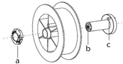
text_image
a b c- Remove the nozzle (a) and contact tube (b) from your MIG/MAG torch.
- Open the generator hatch.
- Position the coil on its support.
- Take note of the drive pin (c) on the coil support. To fit a 200 mm coil, tighten the plastic coil holder (a) as far as it will go.
- Adjust the brake knob (b) to prevent the inertia of the spool tangling the wire when the weld is stopped. As a general rule, do not overtighten, as this will cause the motor to overheat.
LOADING OF FILLER WIRE
natural_image
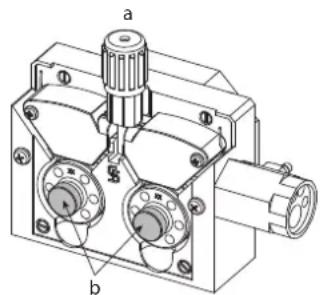
Technical line drawing of a mechanical device with labeled parts (a and b), no readable text or symbols present.To change the rollers, proceed as follows:
- Loosen the knob (a) as far as it will go and lower it.
- Unlock the rollers by unscrewing the retaining screws (b).
- Fit the correct motor rollers for your application and screw the retaining screws back in.
The rollers supplied are double groove rollers: - aluminium ∅ 1.0/1.2 (P1 + P2 + P3)
- steel ∅ 0.8/1.0 (P2 + P3)
- steel ∅ 0.6/0.8 (P3).
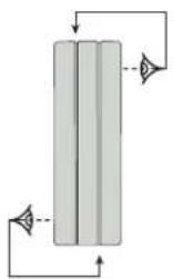
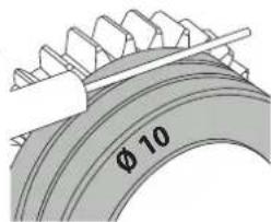
- Check the marking on the roller to ensure that the rollers are suitable for the wire diameter and the wire material (for a ∅ 1.0 wire, use the ∅ 1.0 groove).
- Use V-grooved rollers for steel and other hard wires.
- Use U-grooved rollers for aluminium and other soft alloy wires.
For example: 10 = ∅ 1.0) →: groove to be used
text_image
φ 10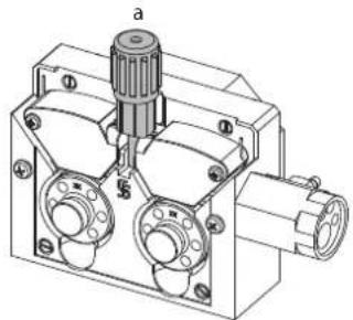
natural_image
Technical line drawing of a mechanical component with no visible text or symbolsTo install the filler metal wire, proceed as follows:
- Loosen the knob as far as it will go and lower it.
- Insert the wire, then close the motorised winder and tighten the knob as indicated.
- Press the torch trigger to activate the motor, a procedure will be displayed on the screen.

Notes:
- A sheath that is too narrow can cause unwinding problems and overheating of the motor.
- The torch connector must also be tight to avoid overheating.
- Make sure that neither the wire nor the spool touches the mechanics of the device, otherwise there is a risk of short-circuit.
RISK OF INJURY FROM MOVING PARTS

Wire feeders have moving parts that can catch hands, hair, clothes or tools and cause injury!
- Do not touch rotating or moving components or drive parts!
- Ensure that housing covers or protective covers remain closed during operation!
- Do not wear gloves when threading the filler wire or changing the filler wire spool.
SEMI- AUTOMATIC WELDING IN STEEL/STEEL (MIG MODE) AUTOMATIC WELDING IN STEEL/STAINLESS STEEL (MAG MODE)
The equipment can weld steel and stainless steel wire from ∅ 0.6 to 1.0 mm (I-A).
Use in steel requires a specific welding gas (Ar+CO2). The proportion of CO2 may vary according to the type of gas used. For stainless steel, use a 2% CO2 mixture. When welding with pure CO2, it is necessary to connect agas preheater to the gas cylinder. For specific gas requirements, please contact your gas distributor. The gas flow rate for steel is between 8 and 15 litres / minute, depending on the environment. To check the gas flow rate on the manometer without unwinding the filler wire, press and hold the n°1 push-button and follow the procedure on the screen. This check should be carried out periodically to ensure optimum welding performance. Refer to the HMI manual.
- Use specific rollers for steel/stainless steel welding.
- Use the capillary tube (designed to guide the wire between the wire feeder rollers and the EURO connector) only for steel/stainless steel welding (I-B).
- Use a special steel/stainless steel torch.
- Contact tube: use a SPECIAL steel/stainless steel contact tube corresponding to the diameter of the wire.
SEMI-AUTOMATIC WELDING IN ALUMINIUM (MIG MODE)
The equipment can weld aluminium wire from ∅ 0.8 to 1.2 mm (I-B).
Use with aluminium requires a specific pure argon gas (Ar). The contact tube, roller groove and torch sheath are designed for this application. Ask your gas distributor for advice on the choice of gas. The gas flow rate for aluminium is between 15 and 20 l/min, depending on the environment and the welder's experience.
When using red or blue sheath (aluminium welding), we recommend using accessory 90950 (I-C). This stainless steel sheath guide improves sheath centring and facilitates wire flow.

Video
- Use specific rollers for aluminium welding.
- Apply minimum pressure to the motorised winder pressure rollers to avoid crushing the wire.
- Use a special aluminium torch. This torch has a Teflon sheath to reduce friction. DO NOT cut the sheath at the edge of the fitting! This sheath is used to guide the wire from the rollers.
- Contact tube: use a SPÉCIAL alu contact tube corresponding to the diameter of the wire.
SEMI-AUTOMATIC WELDING IN CUSI AND CUAL (BRASHING MODE)
The equipment can weld CuSi and CuAl wire of ∅ 0.8 and 1.0 mm.
In the same way as for steel, the capillary tube must be fitted and a torch with a steel sheath must be used. When brazing, pure argon (Ar) must be used.
GAS CONNECTION
- Fit a suitable pressure reducer to the gas cylinder. Connect it to the welding unit using the hose supplied. Fit the clamps to prevent leaks.
- Make sure the gas cylinder is securely held in place by securing the chain to the generator.
- Adjust the gas flow rate by turning the knob on the pressure regulator.
NB: to make it easier to adjust the gas flow rate, activate the motorised reel rollers by pressing the torch trigger (loosen the motorised reel brake knob to avoid dragging the wire). Maximum gas pressure: 0.5 MPa (5 bar).
This procedure does not apply to welding in "No Gas" mode.
RECOMMENDED COMBINATIONS
| (mm) | Current (A) ∅ Wire (mm) ∅ Nozzle (mm) Flow rate (L/min) | ||||
| MIG | 0.8 > 2 20 > 100 | 0.8 12 10-12 | |||
| 2 > 4 100 > 200 | 1.0 12-15 12-15 | ||||
| 4 > 8 200 > 300 | 1.0/1.2 15-16 15-18 | ||||
| 8 > 15 300 > 500 | 1.2/1.6 | 16 18-25 | |||
| MAG | 0.6 > 1.5 15 > 80 | 0.6 12 | 8-10 | ||
| 1.5 > 3 80 > 150 | 0.8 12-15 10-12 | ||||
| 3 > 8 150 > 300 | 1.0/1.2 | 15-16 12-15 | |||
| 8 > 20 300 > 500 | 1.2/1.6 | 16 15-18 | |||
MIG / MAG WELDING MODE (GMAW/FCAW)
| Welding processes | ||||
| Parameters | Settings | Manual | Synergic | |
| Torque material/gas | - Fe Ar 15% CO2- ... | - | ✓ | Choice of material to be welded.Synergic welding parameters |
| Wire diameter | ∅ 0.6 > ∅ 1.2 mm | - | ✓ | Choice of wire diameter |
| Trigger behaviour | 2T, 4T | ✓ | ✓ | Choice of trigger weld management mode |
| Tacking mode | Spot, Spot-Delay | Choice of aiming mode | ||
| 1^st Setting | ThicknessCurrentSpeed | - | ✓ | Choice of main setting to be displayed (Thickness of the part to be welded, average welding current or wire speed). |
Access to certain welding parameters depends on the display mode selected: Parameters/Display mode: Easy or Expert. Refer to the HMI manual.
WELDING PROCESSES
For more information on GYS synergies and welding processes, scan the QR code :

EASY
2 WELDING MODES
•Welding (continuous)
- Chain-stitch
This welding mode is used to join very thin sheet metal, limiting the risk of piercing and distorting the sheet. Chain-stitch welding is performed manually using the trigger.
EXPERT
TACKING MODE
- Spot
This welding mode is used to pre-assemble parts before welding. Tacking can be manual using the trigger or timed with a predefined tacking delay. This tacking time ensures better reproducibility and non-oxidised points.
- Spot-Delay
This is a tacking mode similar to Spot, but with a sequence of tacks and a defined stop time as long as the trigger is held down. This function can be used to weld very thin steel or aluminium sheets, limiting the risk of drilling and deformation of the sheet (especially for aluminium welding).
WELDING MODE
- 2T or 4T
SETTING THE PARAMETERS
| Unit | ||
| Burnback - | Function preventing the risk of wire sticking at the end of the bead. This time corresponds to a rise of the wire out of the molten bath. | |
| Crater Filler %/s | This stop current is a phase after the current descent ramp.It is adjusted in intensity (% of the welding current) and in time (seconds). | |
| Delay s Time between the end of a spot (excluding Post-gas) and the start of a new spot (including Pre-gas). | ||
| Thickness mm | Synergy allows fully automatic parameter setting. Action on the thickness automatically sets the appropriate voltage and wire speed. | |
| Fogging s Current descent ramp. | ||
| Hot Start %/s | Hot Start is an overcurrent at start-up to prevent the wire sticking to the workpiece. It is set in intensity (% of the welding current) and time (seconds). | |
| Intensity A The welding current is set according to the type of wire used and the material to be welded. | ||
| I Start - Adjustment of the starting current. | ||
| Arc length - Used to adjust the distance between the end of the wire and the molten pool (tension adjustment). | ||
| Pre-gas s Time for purging the torch and creating the gas protection before striking. | ||
| Point s Defined duration. | ||
| Post-gas | s | Time for maintaining the gas protection after the arc is extinguished. This protects the workpiece and electrode against oxidation. |
| Self | - | Dampens the welding current to a greater or lesser extent. To be set according to the welding position. |
| Spot | s Defined duration. | |
| Voltage | V Influence on the width of the bead. | |
| Upslope | s Gradual ramping up of the current. | |
| Approach speed | - | Progressive wire speed. Before priming, the wire arrives slowly to create the first contact without causing jolts. |
| Wire speed | m/min | Quantity of filler metal deposited and indirectly the welding intensity and penetration. |
Access to certain welding and tacking parameters depends on the welding process (Manual, Synergic) and the display mode selected (Easy or Expert). Refer to the HMI manual.
CHECKING THE GAS FLOW
To check the gas flow on the pressure gauge without unwinding the welding wire, press and hold the n°1 push-button and follow the procedure on the screen. This check should be carried out periodically to ensure optimum welding performance. Refer to the HMI manual.
FAULTS, CAUSES, REMEDIES
| SYMPTOMS | POSSIBLE CAUSES | REMEDIES |
| The flow of welding wire is not constant. | Spatter is obstructing the orifice | Clean the contact tube or replace it. |
| The wire is slipping in the rollers. | Replace the anti-adhesion product. | |
| One of the rollers is slipping. | Check that the roller screw is tight. | |
| The torch cable is twisted. | The torch cable must be as straight as possible. | |
| The unwinding motor does not work. | Coil brake or roller too tight. | Loosen brake and rollers |
| Poor wire feed. | Wire guide sheath dirty or damaged. | Clean or replace. |
| Roller shaft key missing | Reposition the key in its seat | |
| Spool brake too tight. | Release the brake. | |
| No current or wrong welding current. | Wrong mains plug connection. | Check the plug connection and check that there is power to the plug. |
| Poor earth connection. | Check the earth cable (connection and condition of the clamp). | |
| No power. | Check the torch trigger. | |
| Wire clogs after the rollers. | Wire guide sheath crushed. Check the sheath and torch body. | |
| Wire jammed in the torch. Replace or clean. | ||
| No capillary tube. Check presence of capillary tube. | ||
| Wire speed too high. Reduce wire speed. | ||
| Welding bead porous. | Gas flow insufficient. | Adjustment range 15 to 20 L / min.Clean the base metal. |
| Empty gas cylinder. Replace it. | ||
| Unsatisfactory gas quality. Replace it. | ||
| Air circulation or influence of wind. Prevent draughts, protect the welding area. | ||
| Gas nozzle too dirty. Clean the gas nozzle or replace it. | ||
| Poor quality of wire. Use a wire suitable for MIG-MAG welding. | ||
| Poor quality of the surface to be welded (rust, etc.) | Clean the workpiece before welding | |
| Gas not connected | Check that the gas is connected to the generator inlet. | |
| Very large spark particles. | Arc voltage too low or too high. See welding parameters. | |
| Incorrect earth connection. | Check and position the earth clamp as close as possible to the area to be welded. | |
| Insufficient shielding gas. Adjust the gas flow. | ||
| No gas at torch outlet Incorrect gas connection | Check the gas inlet connection | |
| Check that the solenoid valve is working | ||
| Error when downloading | The data on the USB key is incorrect or corrupted. | Check your data. |
| Backup problem | You have exceeded the maximum number of backups. | You need to delete programs.The number of backups is limited to 200. |
| Automatic deletion of JOBS. | Some of your jobs have been deleted because they were no longer valid with the new synergies. | - |
| USB key problem | No JOB is detected on the USB key - | |
| More memory space in the product Free up space on the USB key. | ||
| File problem | The "..." file does not match the synergies downloaded to the product | The file was created with synergies that are not present on the machine. |
| Update problem | The USB key does not seem to be recognised.The display for step 4 of the update procedure does not appear on the screen. | 1- Insert the USB key into its slot.2- Switch on the generator.3- Press and hold down the HMI wheel to force the update. |
WARRANTY CONDITIONS
The warranty covers all manufacturing defects or faults for 2 years from the date of purchase (parts and labour).
The warranty does not cover:
• Any other damage due to transport.
•Normal wear and tear of parts (e.g. cables, clamps, etc.).
- Incidents due to incorrect use (incorrect power supply, dropping, dismantling).
•Environment-related faults (pollution, rust, dust).
In the event of a fault, return the appliance to your distributor, enclosing:
- dated proof of purchase (till receipt, invoice, etc.)
- a note explaining the fault.
natural_image
Pure diagram of a vertical cylindrical structure with directional arrows indicating flow or movement (no text or symbols)natural_image
Technical line drawing of a mechanical component with no visible text or symbolsnatural_image
Technical line drawing of a mechanical device with labeled parts (a and b), no readable text or symbols present.natural_image
Technical line drawing of a mechanical component with no visible text or symbolsWAARSCHUWINGEN - VEILIGHEIDSINSTRUCTIES
ALGEMENE INSTRUCTIES
natural_image
Technical line drawing of a mechanical device with labeled parts (a and b), no readable text or symbols present.natural_image
Pure diagram of a vertical cylindrical vessel with internal flow arrows, no text or symbols presentnatural_image
Technical line drawing of a mechanical component with labeled parts (a, b, c) and no readable text or symbols.natural_image
Technical line drawing of a mechanical component with labeled parts (a and b), no readable text or symbols present.natural_image
Technical line drawing of a mechanical component with no visible text or symbolstext_image
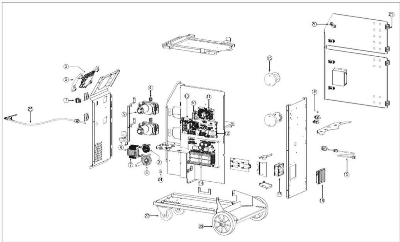
Exploded view diagram of a mechanical device with numbered parts for identification and assembly reference.P2
text_image
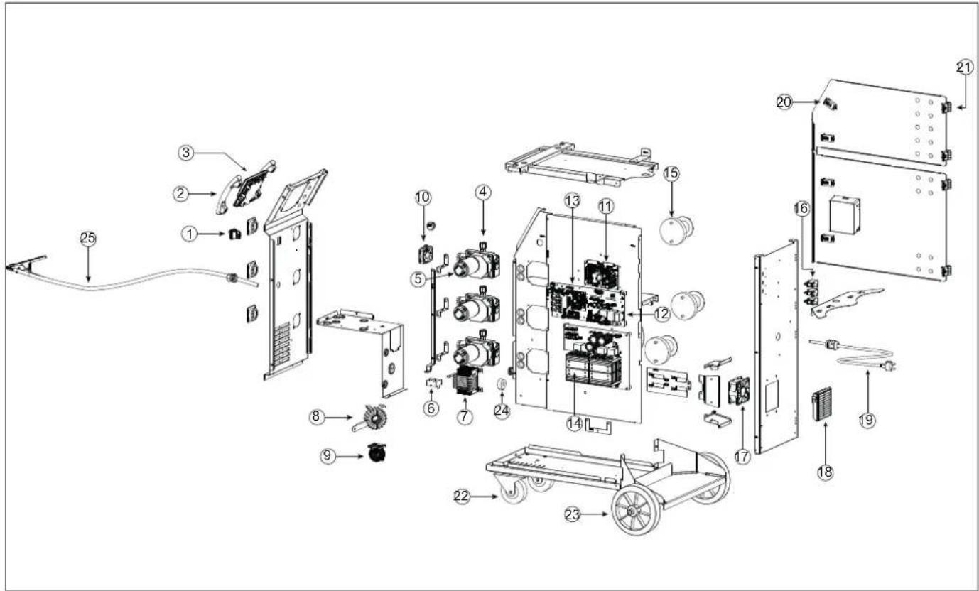
Exploded view diagram of an electronic device with numbered components for identificationP3
text_image
Exploded view diagram of a mechanical device with numbered components for identification| P1 GYS AUTO P2 GYS AUTO P3 GYS AUTO | |||||||
| 230 V | 208/240 V | 230 V | 208/240 V | 230 V | 208/240 V | ||
| 1 | Interrupteur bipolaire / Two-pole switch / Zweipoliger Schalter / Interruptor bipolar /Двухполюсный переключатель / Tweepolige schakelaar / Interruttore bipolare | 52472 | 52472 | 52472 | |||
| 2 | Poignée plastique / Plastic handle / Kunststoffgriff / Asa de plástico / Пластиковая ручка /Plastic handvat / Maniglia in plastica | 56047 | 56047 | 56047 | |||
| 3 | HM / HMI E0255C E0255C E0255C | ||||||
| 4 | Motodévidoir / Wire feeder motor / 51207 51207 51207 | ||||||
| 5 | Carte tachymétrie / Tachometer board / Tachymeterkarte / Tarjeta de taquimetría / Плататахометра / Tachometerbord / Scheda tachimetrica | E0153C | E0153C | E0153C | |||
| 6 | Capteur de courant / Current sensor / Stromsensor / Sensor de corriente / Датчик тока /Huidige sensor / Sensore di corrente | 64463 | 64463 | 64463 | |||
| 7 | Self de sortie / Output self / Ausgangsdrossel / Inductancia de salida / Вывести себя /Induttanza di uscita | 63739 | 63739 | 63739 | |||
| 8 | Transformateur torique / Toroidal transformer / Ringkerntransformator / Transformadortoroidal / Тороидальный трансформатор / Ringkerntransformator / Trasformatore toroidale | 63561 | 63561 | 63561 | |||
| 9 | Self PFC 63691 63691 63691 | ||||||
| 10 | Ventilateur 60x60x20 / Fan 60x60x20 / Ventilator 60x60x20 / Ventilador 60x60x20 /Вентилятор 60x60x20 / Ventilator 60x60x20 / Ventilatore 60x60x20 | 51018 | 51018 | 51018 | |||
| 11 | Carte alimentation / Power supply board / Stromversorgungsplatine / Tarjeta de alimentación / Плата питания / Voedingskaart / Scheda di alimentazione | E0169C | E0169C | E0169C | |||
| 12 | Circuit principal / Main circuit / Hauptstromkreis / Circuito principal / Главная цепь / Hoo-fdcircuit / Circuito principale | E0201C | E0238C | E0202C | |||
| 13 | Circuit contrôle / Control circuit / Kontrollkreis / Circuito de control / Схема управления /Besturingscircuit / Circuito di controllo | E0215C | E0215C | E0215C | |||
| 14 | Carte de puissance / Power board / Power-Karte / Tarjeta de alimentación / Силоваяплата | E0223C | E0223C | E0223C | |||
| 15 | Support bobine / Reel Holder / Spulenhalter / Portabobinas / Поддержка бобины / Spoel-houder / Supporto per bobine | 71613 | 71602 | 71608 | 71602 | ||
| 16 | Electrovanne / Solenoid valve / Magnetventil / Electroválvula / Электромагнитныйклапан / Magneetventiel / Valvola a solenoide | 70991 | 70991 | 70991 | |||
| 17 | Ventilateur 92x92x38 / Fan 92x92x38 / Ventilator 92x92x38 / Ventilador 92x92x38 /Вентилятор 92x92x38 / Ventilator 92x92x38 / Ventilatore 92x92x38 | 50999 | 50999 | 50999 | |||
| 18 | Grille plastique ventilateur / Plastic fan grill / Ventilator mit Kunststoffgitter / Rejilla deplástico del ventilador / Пластиковая решетка вентилятора / Plastic ventilatorrooster /Griglia della ventola in plastica | 51011 | 51011 | 51011 | |||
| 19 | Cordon secteur / Mains cable / Netzkabel / Cable de red / Сетевой кабель / Netkabel /Cavo di rete | 21588 F | 1018 21588 | F1018 2 | 1588 F1018 | ||
| 20 | Verrou affleurant / Lock / Sperren / Cerradura / Замок / Slot / Blocco | 71003 | 71003 | 71003 | |||
| 21 | Charnière / Hinge / Scharnier / Bisagra / петля / Scharnier / Cerniera | 56239 | 56239 | 56239 | |||
| 22 | Roue pivotante / Castor whell / Schwenkbares Rad / Rueda giratoria / Кастор хелл /Zwenkwiel / Ruota girevole | 71360 | 71360 | 71360 | |||
| 23 | Roue de diamètre 200 / Wheel diameter 200 / Rad mit einem Durchmesser von 200 /Rueda de 200 mm de diámetro / Диаметр колеса 200 / Diameter wiel 200 / Ruota da 200mm di diametro | 71375 | 71375 | 71375 | |||
| 24 | Transformateur de courant / Current transformer / Stromtransformator / Transformador decorriente / Трансформатор тока / Stroomtransformator / Trasformatore di corrente | 63832 | 63832 | 63832 | |||
| 25 | Câble de masse / Earth cable / Erdungskabel / Cable de tierra / Земляной кабель /Aardkabel / Cavo di terra | A0216ST | A0216ST | A0216ST | |||
CIRCUIT DIAGRAM / SCHALTPLAN / DIAGRAMA ELECTRICO / ЭЛЕКТРИЧЕСКАЯ СХЕМА / ELEKTRISCHE SCHEMA / SCEMA ELETTRICO
P1 230V & 208/240V
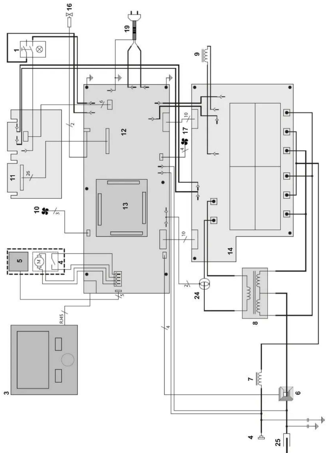
text_image
Technical schematic diagram of an electrical or mechanical system with numbered components and labeled connectionsCIRCUIT DIAGRAM / SCHALTPLAN / DIAGRAMA ELECTRICO / ЭЛЕКТРИЧЕСКАЯ СХЕМА / ELEKTRISCHE SCHEMA / SCEMA ELETTRICO
P2 230V & 208/240V
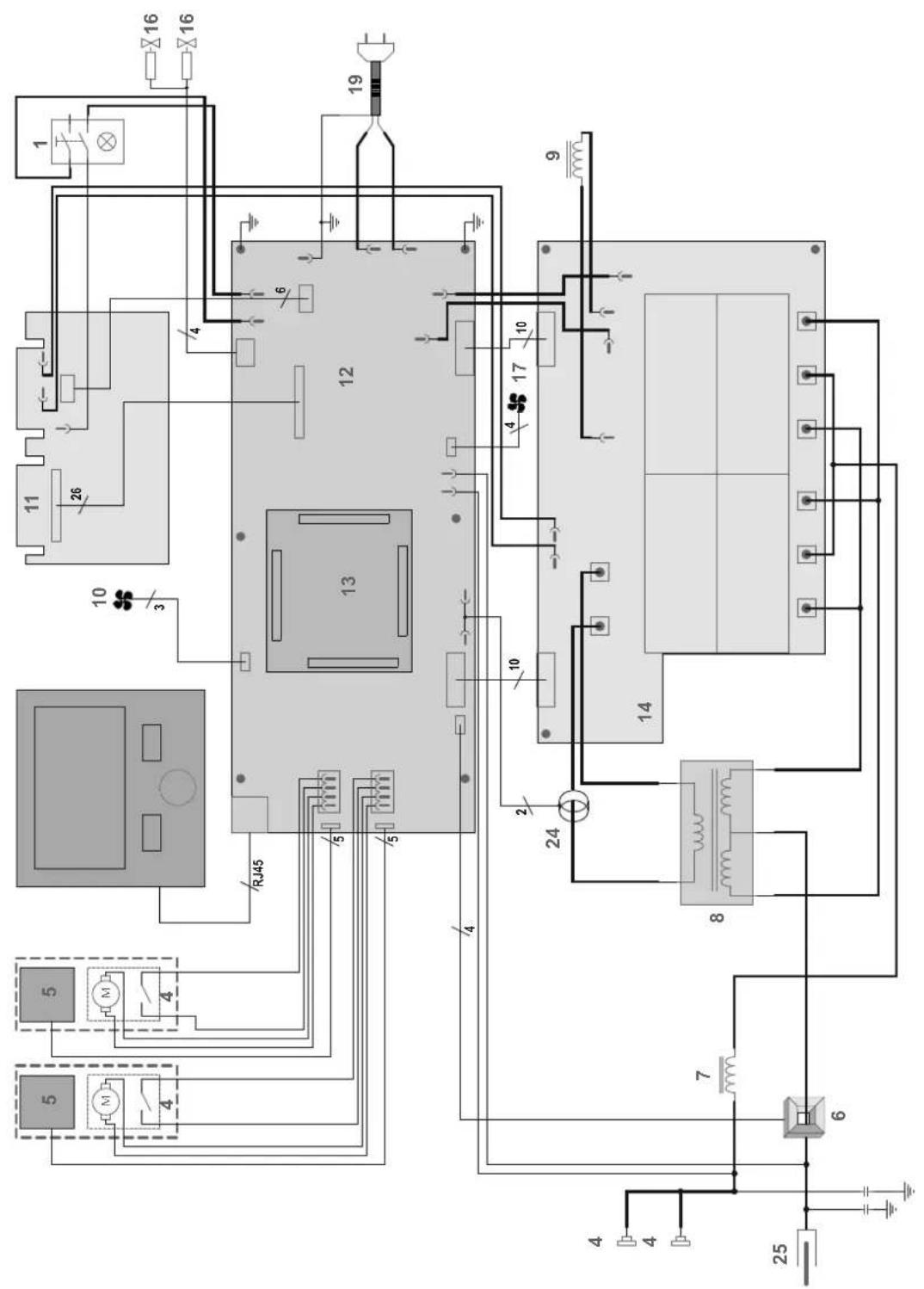
text_image
Electrical schematic diagram with numbered components and wiring connectionsCIRCUIT DIAGRAM / SCHALTPLAN / DIAGRAMA ELECTRICO / ЭЛЕКТРИЧЕСКАЯ СХЕМА / ELEKTRISCHE SCHEMA / SCEMA ELETTRICO
P3 230V & 208/240V
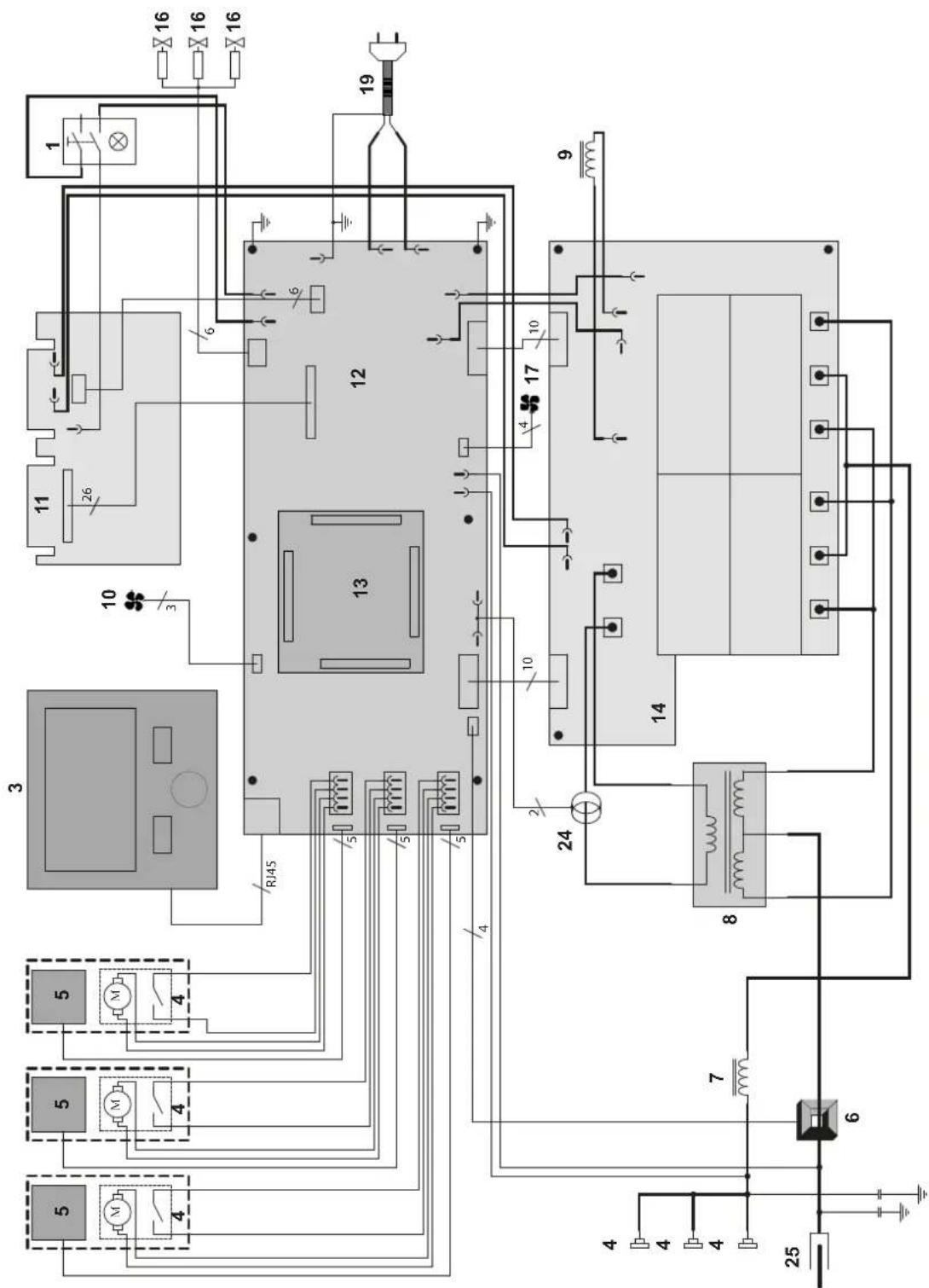
text_image
Electrical schematic diagram with numbered components and wiring connectionsTECHNICAL SPECIFICATIONS / TECHNISCHE DATEN / ESPECIFICACIONES TÉCNICAS / ТЕХНИЧЕСКИЕ СПЕЦИФИКАЦИИ / TECHNISCHE GEGEVENS / SPECIFICHE TECNICHE
| P1 GYS AUTO P2 GYS AUTO P3 GYS AUTO | |||||||
| 230 V 208/240 V 230 V 208/240 V 230 V 208/240 V | |||||||
| Tension d'alimentation / Power supply voltage / Versorgungsspannung / Tensión de red eléctrica /Напряжение питания / Voedingsspanning / Tensione di alimentazione | U1 | 230 V 208/240 V 230 V 208/240 V 230 V 208/240 V | |||||
| Fréquence secteur / Mains frequency / Netzfrequenz / Frecuencia / Частота сети / Frequentie sector / Frequenza settore | 50 / 60 Hz | ||||||
| Nombre de phases / Number of phases / Anzahl der Phasen / Número de fases / Количество фаз / Aantal fasen / Numero difase | 1 | ||||||
| Fusible disjoncteur / Fuse / Sicherung / Fusible disyuntor / Плавкий предохранитель прерывателя / Zekering hoofdschakelaar / Fusibile disgiuntore | 16 A | ||||||
| Courant d'alimentation effectif maximal / Maximum effective supply current / Corriente de alimentación efectiva máxima / Maximale effectieve voedingsstroom / Corrente di alimentazione effettiva massima /Maksymalny efektywny prąd zasilania | I1eff | 13.8 A 15.7 | A 13.8 A 15.7 A 13.8 A 15.7 A | ||||
| Courant d'alimentation maximal / Maximum supply current / Corriente de alimentación máxima / Maximalevoedingsstroom / Corrente di alimentazione massima / Maksymalny prąd zasilania | I1max | 30.4 A 33.6 | A 30.3 A 33.6 A 30.4 A 33.6 A | ||||
| Section du cordon secteur / Mains cable section / Sectie netsnoer / Sección del cable de alimentación / Sezione del cavo di alimentazione / Odcinek przewodu zasilajacego | 3 x 2.5 mm ^2 | x AWG 12 3 x 2.5 | mm ^2 x AWG 12 | 3 x 2.5 mm ^2 x AWG 12 | 3 x 2.5 mm ^2 x AWG 12 | ||
| Puissance active maximale consommée / Maximum active power consumed / Consumo máximo de energía activa / Maximaleactieve verbruikte vermogen / Potenza attiva massima consumata / Maksymalny pobór mocy czynnej | 6550 W | ||||||
| Consommation au ralenti / Idle consumption / Consumo en ralentizado / Stationair verbruik / Consumo al minimo / Zużycie nabiegu jalowym | 15.9 W | ||||||
| Rendement à I2max / Efficiency at I2max / Eficiencia a I2máx / Rendement bij I2max / Efficienza a I2max / Sprawność przyI2max | 84 % | ||||||
| Facteur de puissance à I2max / Power factor at I2max / Factor de potencia a I2max / Inschakelduur bij I2max / Ciclo di potenza a I2max / Współczynnik mocy przy I2max | λ | 0.995 | |||||
| Classe CEM / EMC class / Classe CEM / Klasse CEM / Classe CEM / Klasa EMC A | |||||||
| Secondaire / Secondary / Sekundär / Secundario / Вторичка / Secondair / Secondario | MIG-MAG(GMAW-FCAW) | ||||||
| Tension à vide / No load voltage / Leerlaufspannung / Tensión al vacío / Напряжение холостого хода / Nullastspanning / Tensione a vuoto (TCO) | 67 V | ||||||
| Nature du courant de soudage / Type of welding current / Tipo de corriente de soldadura / Type lasstroom / Tipo di corrente disaldatura / Rodzaj prądu spawania | DC | ||||||
| Modes de soudage / Welding modes / Modos de soldadura / Lasmodules / Modalità di saldatura / Tryby spawania MIG-MAG | |||||||
| Courant de soudage minimal / Minimum welding current / Corriente mínima de soldadura / Minimale lasstroom / Correnteminima di saldatura / Minimalny prąd spawania | 10 A | ||||||
| Courant de sortie nominal / Rate current output / nominaler Arbeitsstrom / Corriente de salida nominal /Номинальный выходной ток / Nominale uitgangsstroom / Corrente di uscita nominale | I2 | 10 → 220 A | |||||
| Tension de sortie conventionnelle / Conventional voltage output / entsprechende Arbeitsspannung / Условноевыходные напряжения / Tensión de salida convencional / Conventionele uitgangsspanning / Tensione diuscita convenzionale | U2 | 14.5 → 25 V | |||||
| Facteur de marche à 40°C (10 min), Norme EN60974-1 / Duty cycle at 40°C (10 min), Standard EN60974-1.Einschaltdauer @ 40°C (10 min), EN60974-1-Norm / Ciclo de trabajo a 40°C (10 min), Norma EN60974-1/ПВ% при 40°C (10 мин), Норма EN60974-1. / Inschakelduur bij 40°C (10 min), Norm EN60974-1, Ciclo di lavoro a 40°C (10 min), Norma EN60974-1. | Imax 20 % | ||||||
| 60 % | 150 A | ||||||
| 100 % | 130 A | ||||||
| Diamètre minimal et maximal du fil d'apport / Minimum and maximum diameter of filler wire / Minimalerund maximaler Durchmesser des Schweißfülldrahtes / Diámetro mínimo y máximo del hilo de soldadura /Минимальный и максимальный диаметр присадочной проволоки / Minimale en maximale diameter vanhet lasdraad / Diametro mínimo e massimo del filo d'apporto | Acier / Steel | 0.6 → 1.0 mm | |||||
| Inox / Stainless | 0.8 → 1.0 mm | ||||||
| Aluminium | 0.8 → 1.2 mm | ||||||
| CuSi / CuA | 0.8 → 1.0 mm | ||||||
| Diamètre minimal et maximal du fil d'apport/ Minimum and maximum diameter of filler wire / Minimaler und maximaler Durch-messer des Schweißfülldrahtes / Diámetro mínimo y máximo del hilo de soldadura / Минимальный и максимальный диаметрприсадочной проволоки / Minimale en maximale diameter van het lasdraad / Diametro mínimo e massimo del filo d'apporto | 0.6 → 1.2 mm | ||||||
| Connectique de torche / Torch connector / Brenneranschluss / Conexiones de antorcha / Соединения горелки / Aansluitingtoorts / Connettori della torcia | Euro | ||||||
| Type de galet / Drive roller type / Drahtführungsrolle-Typ / Tipo de rodillo / Тип ролика / Type draadaanvoerrol / Tipo di rullo | B | ||||||
| Vitesse de dévidage / Motor speed / Motor-Drehzahl / Velocidad de motor / Скорость двигателя / Snelheid motor / Velocità delmotore | 1.0 → 20 m/min | ||||||
| Puissance du moteur / Motor power / Leistung des Motors / Potencia del motor / Vermogen van de motor / Potenza del motore | 50 W | ||||||
| Diamètre maximal de la bobine d'apport / Maximum diameter of the supply reel / Maximaler Durchmesser der Schweißfülldra-htspule / Diámetro máximo de la bobina de alambre / Максимальный диаметр проволочной бобины / Maximale diameter vande spoel / Diametro massimo della bobina d'apporto | ∅ 300 mm ∅ | 300 mm ∅ | 300 mm ∅ | 300 mm ∅ 200 mm ∅ 200 mm | |||
| Poids maximal de la bobine de fil d'apport / Maximum weight of the filler wire reel / Maximales Gewicht der Schweißfülldrahtspule / Peso máximo de la bobina de alambre / Максимальный вес проволочной бобины / Maximale gewicht van de spoel / Peso massimo della bobina del filo d'apporto | 18 kg 18 kg | 18 kg 18 kg 5 kg | 5 kg | ||||
| Pression maximale de gaz / Maximum gas pressure / Maximaler Gasdruck / Presión máxima del gas / Максимальное давление газа / Maximale gasdruk / Pressione massima del gas | 0.5 MPa (5 bar) | ||||||
| Température de fonctionnement / Functionning temperature / Betriebstemperatur / Temperatura de funcionamiento / Рабочая температура / Gebruikstemperatuur / Temperatura di funzionamento | -10°C → +40°C | ||||||
| Température de stockage / Storage temperature / Lagertemperatur / Temperatura de almacenaje / Температура хранения / Bewaartemperatuur / Temperatura di stoccaggio | -20°C → +55°C | ||||||
| Degré de protection / Protection level / Schutzart / Grado de protección / Степень защиты / Beschermingsklasse / Grado di protezione | IP23S | ||||||
| Classe d'isolation minimale des enroulements / Minimum coil insulation class / Clase minima de aislamiento del bobinado / Minimale isolatieklasse omwikkelingen / Classe minima di isolamento degli avvolgimenti / Minimalna klasa izolacji okablowania | B | ||||||
| Dimensions (Lxlxh) / Dimensions (LxWxH) / Abmessungen (Lxbxt) / Dimensiones (Lxlxh) / Размеры (ДхШхВ) / Afmetingen (Lxlxh) / Dimensioni (Lxlxh) | 78 x 45 x 80 cm 86 x 63 x 93 cm 86 x 63 x 93 cm | ||||||
| Poids / Weight / Gewicht / Bec / Peso / Gewicht / Peso 45 kg | 59 kg | 62 kg | |||||
The duty cycles are measured according to standard EN80574-1 à 40°C and on a 10 min cycle. While under intensive use (> to duty cycle) the thermal protection can turn on, in that case, the arc switches off and the indicator switches on. Keep the machine's power supply on to enable cooling until thermal protection cancellation. The welding power source describes an external drooping characteristic. The power supply shows a flat output pattern... In some countries, UO is called TCO.