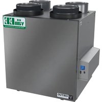
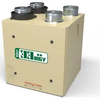
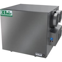
G2400EE - Air Conditioning vänEE - Free user manual and instructions
Find the device manual for free G2400EE vänEE in PDF.

| Product Type | Energy Recovery Ventilator (ERV) |
| Brand | vänEE |
| Model | G2400EE |
| Power Supply | 120 V, 60 Hz, standard 3-prong grounded plug |
| Electrical Protection | 3 A fuse (type 3AG) |
| Motor | Variable speed ECM motor |
| Recovery Core | Energy recovery exchanger (ERV) – 10-year warranty |
| Filters | 2 washable filters (mild soap and warm water) |
| Compatible Controls | X-Touch or Gold-Touch wall controls (main) 20/40/60 minute push buttons (auxiliary, up to 5) |
| Operating Modes | Continuous (CONT), Turbo, 20/40/60 minutes, Recirculation (RECIRC) |
| Defrost | Automatic defrost cycles (Standard, Plus, Discretion) |
| Maximum Airflow (TURBO) | Up to approx. 226 ft³/min (depending on adjustment and installation) |
| Maintenance Indicator | Reminder icon on wall control (about 4 times/year) |
| Seasonal Maintenance | Clean filters every 3 months |
| Annual Maintenance | Clean core and interior of unit |
| Electrical Connection | Class 2 low-voltage wiring for controls and furnace synchronization |
| Installation | Suspended by chains or on wall mount; flexible or rigid ducts |
| Parts Warranty | 5 years |
| Energy Recovery Core Warranty | 10 years |
| Certification | ENERGY STAR® (Canada) |
| Usage | Residential (Group C, D, E, F buildings per building code) |
Frequently Asked Questions - G2400EE vänEE
User questions about G2400EE vänEE
0 question about this device. Answer the ones you know or ask your own.
Ask a new question about this device
Download the instructions for your Air Conditioning in PDF format for free! Find your manual G2400EE - vänEE and take your electronic device back in hand. On this page are published all the documents necessary for the use of your device. G2400EE by vänEE.
USER MANUAL G2400EE vänEE
USER AND INSTALLER MANUAL
natural_image
Simple line drawing of a rectangular structure with four small structures on top and two at the bottom, no text or symbols present.V80165
VENMAR AVS
X24 ERV ECM
X24 HRV ECM
X30 ERV ECM
X30 HRV ECM
VENMAR/VÄNEE
X24 ERV ECM-N
X24 HRV ECM-N
X30 ERV ECM-N
X30 HRV ECM-N
VÄNEE GOLD SERIES
G2400E ECM
G2400H ECM
G3000E ECM
G3000H ECM
ABOUT THESE UNITS
- New information about extended defrost setting, see page 15.
- The only main wall controls compatible with these units are the X-Touch or Gold-Touch.
- New balancing procedure, see page 16.
- The terminal connectors for these units are already mounted to the electronic board.
READ AND SAVE THESE INSTRUCTIONS

7 72371 13550 5

ENERGY STAR
These products earned the ENERGY STAR ^® by meeting strict energy efficiency guidelines set by Natural Resources Canada and the US EPA. They meet ENERGY STAR requirements only when used in Canada.
Please take note that this manual uses the following symbols to emphasize particular information:
WARNING
Identifies an instruction which, if not followed, might cause serious personal injuries including possibility of death.
CAUTION
Denotes an instruction which, if not followed, may severely damage the unit and/or its components.
NOTE: Indicates supplementary information needed to fully complete an instruction.
LIMITATION
For an installation and use in Canada only. Intended for a building on which Part 9 of division B from the effective version of the National Building Code of Canada applies with additional restrictions and exception (see section 4 for more details). Installation work and electrical wiring must be done by a qualified person in accordance with all applicable codes and standards, including fire-rated construction codes and standards.
⚠ WARNING
TO REDUCE THE RISK OF FIRE, ELECTRIC SHOCK, OR INJURY TO PERSON(S) OBSERVE THE FOLLOWING:
- Use this unit only in the manner intended by the manufacturer.
- Before servicing or cleaning this unit, disconnect the power cord from the electrical outlet.
- This unit is not designed to provide combustion and/or dilution air for fuel-burning appliances.
- When cutting or drilling into a wall or ceiling, do not damage electrical wiring and other hidden utilities.
- Do not use this unit with any solid-state speed control device other than those specified in section 6.
- This unit must be grounded. The power supply cord has a 3-prong grounding plug for your personal safety. It must be plugged into a mating 3-prong grounding receptacle, grounded in accordance with the national electrical code and local codes and ordinances. Do not remove the ground prong. Do not use an extension cord.
- Do not install in a cooking area or connect directly to any appliances.
- Do not use to exhaust hazardous or explosive materials and vapors.
- When performing installation, servicing or cleaning this unit, it is recommended to wear safety glasses and gloves.
- When applicable local regulation comprises more restrictive installation and/or certification requirements, the aforementioned requirements prevail on those of this document and the installer agrees to conform to these at his own expense.
- Due to the weight of the unit, two installers are recommended to perform installation
CAUTION
- To avoid prematurely clogged filters, turn the unit OFF during construction or renovation.
- Please read specification label on product for further information and requirements.
- Be sure to duct air outside – Do not intake/exhaust air into spaces within walls or ceiling or into attics, crawl spaces, or garage. Do not attempt to recover the exhaust air from a dryer or a range hood.
- Do not run any air ducts directly above or within 2 ft (0.61 m) of a furnace or its supply plenum, boiler, or other heat-producing appliances. If a duct has to be connected to the furnace return plenum, it must be connected 10' (3.1 m) away from plenum's connection to the furnace.
- The ductwork is intended to be installed in compliance with all applicable local and national codes.
- When leaving the house for a long period of time (more than two weeks), a responsible person should regularly check if the unit operates adequately.
- If the ductwork passes through an unconditioned space (e.g.: attic), the unit must operate continuously except when performing maintenance and/or repair. Also, the ambient temperature of the house should never drop below 18^ C ( 65^ F).
- At least once a year, the unit mechanical and electronic parts should be inspected by qualified service personnel.
- Do not use your unit during construction or renovation of your house or when sanding drywall. Certain types of dust and vapors may damage your ventilation system.
- During winter, make sure that the outside intake and exhaust hoods are free from any snow. During a big snow storm, check that your unit doesn't draw in any snow. If it does, turn the unit OFF for a few hours.
- Since the electronic control system of the unit uses a microprocessor, it may not operate correctly because of external noise or very short power failure. If this happens, unplug the unit and wait approximately 10 seconds. Then, plug the unit in again.
- Do not make excessive use of fragrance appliances or chemicals since some may damage the unit components material.
TABLE OF CONTENTS
- USING THIS UNIT .... 4
- USER SERVICING INSTRUCTIONS ..... 4
2.1 Seasonal maintenance....4
2.2 Annual maintenance....5
- USER'S TROUBLESHOOTING .... 5
-
WARRANTY 6
-
INSTALLATION......8
5.1 Locating the unit....8
5.2 Mounting the unit....8
5.2.1 Using chains and springs....8
5.2.2 Using the wall brackets 9
5.3 Installing the ductwork and the registers .....9
5.3.1 Fully Ducted System....9
5.3.2 Exhaust Ducted System - Supply Side.... 10
5.3.3 Exhaust Ducted System - Return Side.... 10
5.3.4 Simplified Installation - Return/Supply 10
5.3.5 Simplified Installation - Return/Return.....11
5.4 Connecting the ducts to the unit.... 11
5.4.1 Insulated flexible ducts....11
5.4.2 Non-insulated flexible ducts ..... 11
5.4.3 Non-insulated rigid ducts .....11
5.5 Installing the exterior hoods ..... 12
5.6 Connecting the drain 12
- WALL CONTROLS.... 13
6.1 Auxiliary wall controls 13
6.2 Main wall control....14
-
ELECTRICAL CONNECTION TO THE FURNACE 14
-
RECIRCULATION AND DEFROST SETTINGS....15
- BALANCING THE UNIT 16
9.1 Before starting....16
9.2 Balancing the unit....17
-
REPLACEMENT PARTS......21
-
WIRING DIAGRAM 23
- TROUBLESHOOTING....24
PRODUCT REGISTRATION CARD - FICHE D'ENREGISTREMENT DU PRODUIT
Address – Adresse Apt. no. – App. City – Ville Province Postal code – Code postal
Country – Pays E-mail address – Courriel Language preferred – Langue de correspondance
Date of purchase – Date d'achat
A. To ensure quiet operation of the ENERGY STAR certified H/ERV, each product model must be installed using sound attenuation techniques appropriate for the installation.
B. The way your heat/energy-recovery ventilator is installed can make a significant difference to the electrical energy you use. To minimize the electricity use of the heat/energy-recovery ventilator, a stand-alone fully ducted installation is recommended. If you choose a simplified installation that operates your furnace air handler for room-to-room ventilation, an electrically efficient furnace that has an electronically commutated (EC) variable speed blower motor will minimize your electrical energy consumption and operating cost.
C. Installation of a user-accessible control with your product model will improve comfort and may significantly reduce the product model's energy use.
1. USING THIS UNIT
CAUTION
Before using this unit for the first time, please take the time to carefully read page 2 of this guide to ensure it is used safely and properly.
This unit performs a 30-second booting sequence at startup. Your main wall control indicates the progression of the booting sequence in percentage. No command will be taken until the unit is fully booted.
You can control your unit using one main wall control, and up to five optional 20/40/60-minute push-buttons, usually located in bathrooms.
Activation of a 20/40/60-minute push-button overrides the current operation mode of the unit, including defrost cycles, and a timer icon will appear on the main control screen.
For more information on the controls, refer to the Main and auxiliary wall control User Guide included with your unit and available on our website.
text_image
CONTVQ0137
2. USER SERVICING INSTRUCTIONS
This unit requires seasonal and annual maintenance. Your main wall control includes a maintenance reminder that lights up 4 times a year.
-
Unplug the unit.
-
Undo both door latches and open the door.
-
Slide out both filters from the top of the recovery core.
-
Wash the filters with a mild soap and lukewarm water, rinse thoroughly and allow to dry completely.
-
Reinstall the filters in the unit.
-
Close the door and plug unit back. The unit will perform a 30-second booting sequence and will resume operating as previously set.
-
Reset the maintenance indicator by holding both the MODE and TURBO keys for 3 seconds.
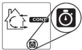
text_image
CONT MVQ0134 Maintenance icon
Would you like to receive occasional informational e-mail offers including product updates and special promotions from us? Yes/No
What problem were you trying to solve with your purchase? (Check each one that applies to you.)
□ Bad odors
□ Respiratory
problems
□ Excess of humidity
□ Temperature
standardization
□ Lack of fresh air
□ Dust
□ Mildew
□ Allerges
□ No specific
problems
□ Others
Please read the following list of criteria carefully. Indicate the importance of your purchase decision on a scale of 1 (less important) to 5 (most important).
Price
Warranty
Product design
Ventilation
capacity
Filler maintenance
indicator
Filtration quality
Recirculation
Heal recovery
Controls
Ease of cleaning
Manufacturer's
reputation
Ease of use
Noise level
Other
Recirculation
Who installed your unit?
Home builder
□ Recommended
installer
□ Friend / family
Contractor
□ Yourself
(1) 2017.1.14
Are you connected? Please do not hesitate to complete the product registration card via our Web site at www.bnv.ca
- Perform steps 1 and 2 from seasonal maintenance.
- Slide both filters and the core out of the unit.
- Clean the inside of the unit with a clean damp cloth and wipe dry.
- Wash the filters with a mild soap and lukewarm water, rinse thoroughly and allow to dry completely.
- Clean the recovery core as follows, according to the type of unit:
| X24 HRV ECM X30 HRV ECM | X24 HRV ECM-N X30 HRV ECM-N | G2400H ECM G3000H ECM | X24 ERV ECM X30 ERV ECM | X24 ERV ECM-N X30 ERV ECM-N | G2400E ECM G3000E ECM |
| Soak the heat recovery core for 3 hours in a solution of lukewarm water and mild soap.Rinse and allow to dry. | CAUTION: DO NOT SOAK THE ENERGY RECOVERY CORERemove the dust on the core using a vacuum cleaner and a soft brush attachment. | ||||
- Reinstall the core back into the unit.
- Reinstall the filters back on the core.
- Close the unit's door.
- Clean the exterior hoods.
- Plug the unit back. The unit will perform a 30-second booting sequence and will resume operating as previously set.
- Reset the maintenance indicator by holding both the MODE and TURBO keys for 3 seconds.
3. USER'S TROUBLESHOOTING
Before trying any of the following, first try unplugging the unit and plugging it back. If the issue is not solved, refer to the table below.
| PROBLEM TRY THIS | ||
| 1. | Nothing works. | Make sure that the unit is plugged in.Make sure that the unit is receiving power from the house circuit breaker or fuse. |
| 2. | An error code starting with E0 (E01, E02, etc.) is displayed on the wall control. | Make sure that the color coded wires have been connected to their appropriate place.Make sure that the wires are correctly connected.Press simultaneously and hold for 10 seconds the % HUM, MODE and TURBO keys to reset the wall control. The user preferences will have to be reset. |
| 3. | An error code starting with E2 (E21, E22, etc.) is displayed on the wall control. | Problem with the ventilation unit. Contact your installer. |
| 4. | A 10-second countdown is displayed on the wall control. | Wait for the end of the countdown without pressing any key. |
| 5. | The snowflake icon is flashing on the wall control screen. | The ventilation unit is in Protection mode; it will get out of this mode by itself.If this situation occurs regularly, or when outdoor temperature is higher than -20°C, contact your installer. |
| 6. | Condensation on windows (air too humid). | Operate the unit on TURBO or CONT mode until the situation is corrected.Leave curtains half-open to allow air circulation.Store all firewood in a closed room with a dehumidifier or in a well ventilated room, or store the wood outdoors.Do not adjust the thermostat of your heating system below 18°C (64°F). |
| 7. | Inside air too dry. | Temporarily use a humidifier.Operate the unit in 20 min/h mode or in RECIRC. mode. |
| 8. | Air too cold at the air supply grille. | Make sure that the exterior hoods are not blocked.Operate the unit in 20 min/h mode or in RECIRC. mode.Install a duct heater. |
| 9. | The main wall control does not work. | The 30-second boot sequence is not completed. See Section 1 on page 4.A 20/40/60-minute push button auxiliary control is in use. See Section 1 on page 4.The protection mode overrides the main control operation (snowflake icon). Refer the main and auxiliary controls user guide. . |
Contact customer service at 1-800-567-3855 for any unresolved issue.
4. WARRANTY
This unit is a high-quality product, built and packaged with care. The manufacturer warrants to the original purchaser of its product, that such product will be free from defects for the period stated below, from the date of original purchase. For all units, the warranty covers parts only against any operational defect. This is a 5-year warranty. Subject to performing the core maintenance according to the recommendations in this guide, the heat recovery core (HRV) has a limited lifetime warranty, and the energy recovery core (ERV) has a 10-year warranty. If any defect should occur, we urge you to read the user guide carefully. If the problem persists, observe the following rules:
RULES TO FOLLOW
If the unit is defective, contact your ventilation contractor (see address on your user manual cover page). The contractor will determine with you the reason for the defect, and if needed, do the replacement or repair. If ever it is impossible to reach your ventilation contractor, call 1-800-567-3855 (in North America); the personnel will be pleased to give you the phone number of a distributor or a service center near you.
REPLACEMENT PARTS AND REPAIR
In order to ensure your ventilation unit remains in good working condition, you must use the manufacturer's genuine replacement parts only. The manufacturer's genuine replacement parts are specially designed for each unit and are manufactured to comply with all the applicable certification standards and maintain a high standard of safety. Any third party replacement part used may cause serious damage and drastically reduce the performance level of your unit, which will result in premature failing. The manufacturer also recommends contacting a service depot certified by the manufacturer for all replacement parts and repair.
BILL OF PURCHASE
No replacement or repair covered by the warranty will be carried out unless the unit is accompanied by a copy of the original bill of purchase. Please retain your original.
MISCELLANEOUS COSTS
In each case, the labor costs for the removal of a defective part and/or installation of a compliant part will not be covered by the manufacturer.
CONDITIONS AND LIMITATIONS
Intended for a building on which Part 9 of division B from the effective version of the National Building Code of Canada applies with additional restrictions and exception as described below.
Part 9 of Division B application according to the effective version of the National Building Code of Canada:
Part 9 of Division B applies to all buildings falling under the effective version of the Canadian Building Code definitions and conditions as listed below:
All building* of 3 storeys or less in building height, having a building area not exceeding 600m^2 , and used for major occupancies classified as of:
Group C ^1 , residential occupancies,
Group D^2 , business and personal services occupancies,
Group E^3 , mercantile occupancies, or
Group F, Divisions 2 ^4 and 3^5 , medium- and low-hazard industrial occupancies.
And all major occupancies classified as of:
Group C ^1 , residential occupancies exceeding 600 m ^2 in building area or exceeding 3 storeys in building height
However, Group F buildings are excluded since the H/ERV have only been evaluated for installation in non-hazardous locations as per the applicable Canadian safety standard.
Refer to the table below for some common examples included in each building group.
| Group & Division Major Occupancy Examples | |
| C Residential Single-family houses, Hostels, | Multi-family buildings |
| D Business and Personal Services Banks, Offices | |
| E Mercantile Department stores, Supermarkets |
Refer to note A-3.1.2.1 from the effective version of the National Building Code of Canada for more examples.
*Building size determination consider internal separation and shall be evaluated in accordance with section 1.3.3.4 from the effective version of the National Building Code of Canada.
For the User
^1 Residential occupancy means the occupancy or use of a building or part thereof by persons for whom sleeping accommodation is provided but who are not harbored for the purpose of receiving care of treatment and are not involuntarily detained.
^2 Business and personal services occupancy (Group D) means the occupancy or use of a building or part thereof for the transaction of business or the rendering or receiving of professional or personal services.
^3 Mercantile occupancy (Group E) means the occupancy or use of a building or part thereof for displaying or selling of retail goods, wares or merchandise.
^4 Medium-hazard industrial occupancy (Group F, Division 2) means an industrial occupancy in which the combustible content is more than 50 kg/m ^2 or 1200 MJ/m ^2 of floor area and no classified as a high-hazard industrial occupancy.
^5 Low-hazard industrial occupancy (Group F, Division 3) means an industrial occupancy in which the combustible content is not more than 50 kg/m^2 or 1200 MJ/m^2 of floor area.
Exception:
Installation within a single classroom is acceptable provided the unit is installed with an independent ducting system, distinct from the HVAC system, which is limited to that classroom and used to ventilate that classroom only. Additional restrictions from this section remain applicable.
Restrictions:
The H/ERV shall not be installed within or be used to exhaust air from an environment that contains:
- Corrosive gas, vapor, emanations or solvents.
- Flammable or explosives gas, vapor, emanations, solvents or dusts.
- High concentrations of perfumes, nail polish or hair treatment products (bleaching, coloring agents, etc) such as from hairdressing or nail salons.
- High concentration of chemical emanations from solvents, paints or other chemical cleaning agent products.
The H/ERV shall not be used to exhaust air exceeding 50% RH and 11° dew point over an extended period (more than 24 hours) when outdoor temperature is below -15°C.
The H/ERV shall not be used to exhaust air from an environment that contains high levels of particles concentration unless the exhaust air is pre-filtered with capture efficiency filters selected relative to the particle size distribution before entering the H/ERV.
The H/ERV shall not be used to exhaust air cooking effluents but could be used to provide ventilation for a kitchen in a group C building of 3 storeys or less in building height, having a building area not exceeding 600 m ^2 only. The stale air exhaust register location must comply with the requirement from the building code and the user manual.
Applications involving airborne pathogens or virus, smoke, harmful gas are not recommended. Such application requires extra care to avoid recirculation and internal cross-contamination. Please contact customer service for more information.
The above warranty applies to all cases where the damage is not a result of poor installation, improper use, mistreatment or negligence, acts of God, or any other circumstances beyond the control of the manufacturer. Furthermore, the manufacturer will not be held responsible for any bodily injury or damage to personal property or real estate, whether caused directly or indirectly by the unit. This warranty supersedes all prior warranties.
CAUTION
Before installing this unit, please take the time to carefully read page 2 of this guide to ensure it is installed safely and properly.
CAUTION
Make sure that no piece of mineral wool will enter in the unit during installation. Otherwise, this could reduce airflow and generate vibrations and noise in the unit.
5. INSTALLATION
5.1 LOCATING THE UNIT
Choose an appropriate location for the unit:
So as to provide easy access to the interior cabinet for quarterly and annual maintenance. Plan for a 27-in. clearance in front of the unit for the door to open. If that is not possible, an 18-in. clearance is acceptable, in which case the door will have to be removed for maintenance to be performed.
- Within a conditioned space with an ambient temperature kept between 18°C (65°F) and 40°C (104°F) and a maximum relative humidity of 60%.
- Close to an exterior wall, so as to limit the length of the insulated flexible duct to and from the unit.
- Away from hot chimneys, electrical panel and other fire hazards.
- Allow for a power source (standard outlet) within 6 feet.
- HRV: close to a drain. If no drain is close by, use a pail to collect run-off.
5.2 MOUNTING THE UNIT
CAUTION
Always make sure that the unit is level.
5.2.1 USING CHAINS AND SPRINGS
The unit can be hung using the provided chains and springs:
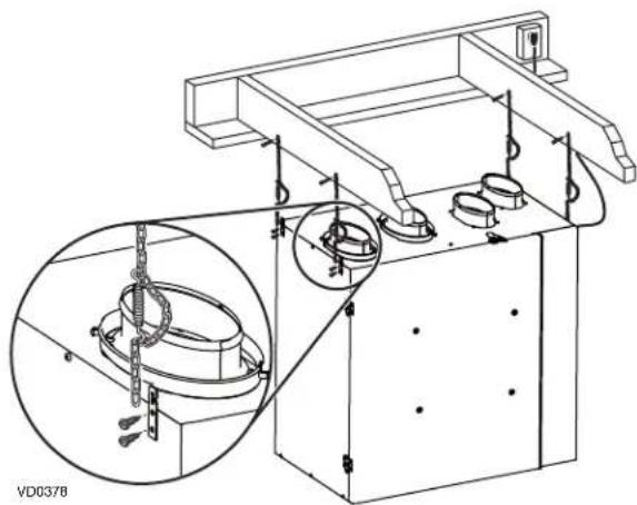
natural_image
Technical line drawing of a mechanical assembly with a magnified inset showing internal components (no text or symbols)For the Installer
5.2.2 USING THE WALL BRACKETS
- Trace a level line on the wall, approximately where the top of the unit will be.
- Using the provided 1.5-in. screws and washers, install the longest of both brackets to the wall making sure to secure it to all of the available studs.
WARNING
The bracket must not be secured to the drywall only.
- Using the provided 1.5-in. screws, assemble both spacers to the lower corners of the back of the unit.
- Using the provided 3/8-in. screws, mount the two other brackets to the top back of the unit, as illustrated below. Do not use an electric screw driver.
- Hang the unit to the bracket on the wall, and secure the smallest bracket to the wall, into a stud if possible.
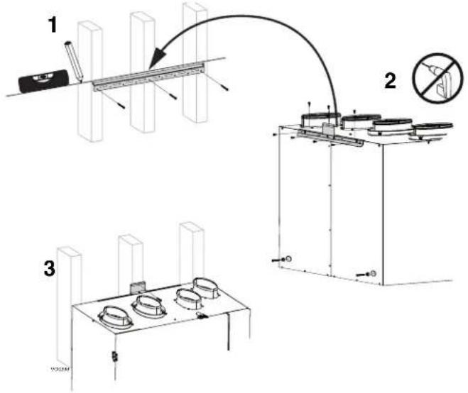
text_image
Technical diagram showing three-step assembly process: tool, measurement setup, and mounting base with no annotations5.3 INSTALLING THE DUCTWORK AND THE REGISTERS
⚠ WARNING
- Never install a stale air exhaust register in a closed room where a combustion device operates, such as a gas furnace, a gas water heater or a fireplace.
- When performing duct connections, always use approved tools and materials. Respect all corresponding laws and safety regulations. Please refer to your local building code.
CAUTION
If ducts have to go through an unconditioned space (e.g.: attic), always use insulated ducts to prevent condensation formation inside and outside ducts, which could cause material damage and/or mold growth. Moreover, if fresh air to building duct and/or stale air from building duct goes/go through an unconditioned space, the unit must be set to operate continuously in cold conditions (below 10°C/50°F). Continuous air movement inside ducts will prevent condensation formation. The unit can be stopped temporarily for maintenance and/or repair purposes in such conditions.
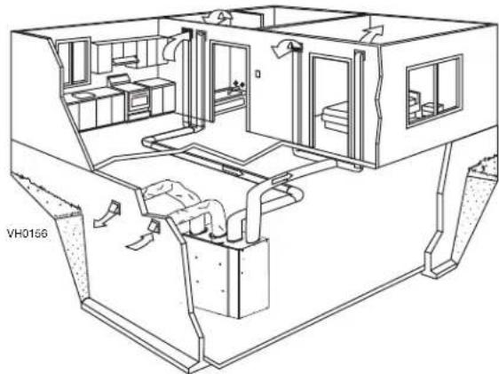
5.3.1 FULLY DUCTED SYSTEM
Stale air from building ductwork:
• Install registers in areas where contaminants are produced: Kitchen, bathrooms, laundry room, etc.
• Install registers on an interior wall, 6 to 12 inches (152 to 305 mm) away from the ceiling OR install them in the ceiling.
• Install the kitchen register at least 4 feet (1.2 m) away from the range.
Fresh air to building ductwork:
• Install registers in bedrooms, dining room, living room and basement.
- Install registers either in the ceiling or high on the walls with the airflow directed towards the ceiling.
- If a register must be installed in the floor, direct the air flow up the wall.
natural_image
Technical line drawing of a multi-level industrial or facility interior with visible structural elements and ventilation ducts (no text or symbols)For the Installer
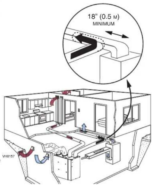
5.3.2 EXHAUST DUCTED SYSTEM - SUPPLY SIDE
CAUTION
When performing duct connections to the furnace supply duct, use metal ducts appropriately sized to support the additional airflow produced by the unit.
Stale air from building ductwork:
• Install registers in areas where contaminants are produced: Kitchen, bathrooms, laundry room, etc.
• Install registers on an interior wall, 6 to 12 inches (152 to 305 mm) away from the ceiling OR install them in the ceiling.
• Install the kitchen register at least 4 feet (1.2 m) away from the range.
Fresh air to building ductwork:
- Cut an opening into the furnace supply duct at least 18 inches (0.5 m) away from the furnace.
- Connect this opening to the fresh air to building port of the unit (use metal ducts, see illustration at right).
- Make sure that the unit duct forms an elbow inside the furnace ductwork.
NOTE : For this type of installation, it is recommended, however, not essential, that the furnace blower be synchronized with the unit.
text_image
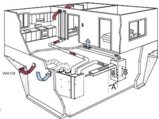
18" (0.5 M) MINIMUM VH01575.3.3 EXHAUST DUCTED SYSTEM - RETURN SIDE
Stale air from building ductwork:
• Install registers in areas where contaminants are produced: Kitchen, bathrooms, laundry room, etc.
• Install registers on an interior wall, 6 to 12 inches (152 to 305 mm) away from the ceiling OR install them in the ceiling.
• Install the kitchen register at least 4 feet (1.2 m) away from the range.
Fresh air to building ductwork:
- Cut an opening into the furnace return duct at least 10 feet (3.1 m) away from the furnace (A+B).
- Connect this opening to the fresh air to building port of the unit (see illustration at right) using metal ducting.
NOTE : For this type of installation, it is recommended, however, not essential, that the furnace blower be synchronized with the unit.
text_image
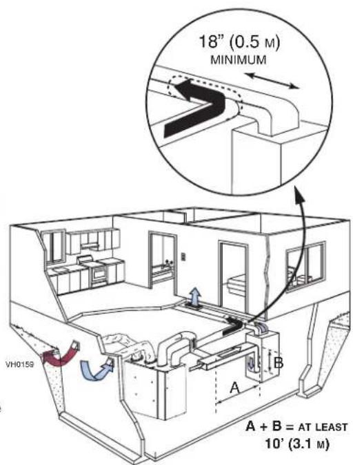
VH0158 A B5.3.4 SIMPLIFIED INSTALLATION - RETURN/SUPPLY
Stale air from building ductwork:
- Cut an opening into the furnace return duct at least 10 feet (3.1 m) (A + B) away from the furnace.
- Connect this opening to the stale air from building port of the unit (as illustrated).
Fresh air to building ductwork:
CAUTION
When performing duct connections to the furnace supply duct, use metal ducts appropriately sized to support the additional airflow produced by the unit.
- Cut an opening into the furnace supply duct at least 18 inches (0.5 m) away from the furnace.
- Connect this opening to the fresh air to building port of the unit (use metal ducts, see illustration at right).
- Make sure that the unit duct forms an elbow inside the furnace ductwork.
NOTE : For this type of installation, it is recommended, however, not essential, that the furnace blower be synchronized with the unit.
text_image
18" (0.5 M) MINIMUM A + B = AT LEAST 10' (3.1 M) VH0159For the Installer
5.3.5 SIMPLIFIED INSTALLATION - RETURN/RETURN
Fresh air to building ductwork:
- Cut an opening into the furnace return duct at least 10 feet (3 m) away from the furnace.
- Connect this opening to the fresh air to building port of the unit (use metal ducts, see illustration at right).
Stale air from building ductwork:
- Cut an opening into the furnace return at least 3 feet (1 m) ahead of the fresh air to building ductwork connection to the furnace return.
- Connect this opening to the stale air from building port of the unit.
- Make sure that both connections to the furnace return duct are at least 3 feet (1 m) apart.
CAUTION
For this type of installation, the furnace must always be synchronized with the unit. See section 7.
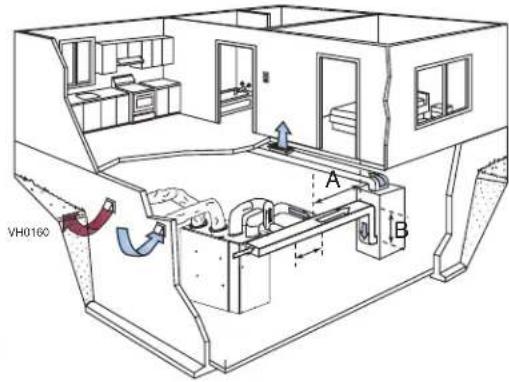
text_image
VH0160 A B5.4 CONNECTING THE DUCTS TO THE UNIT
CAUTION
- If ducts have to go through an unconditioned space (e.g.: attic), always use insulated ducts.
• Make sure the vapor barrier on the insulated ducts does not tear during installation to avoid condensation within the ducts.
• Always use insulated ducts to connect the Fresh air from outdoors and Stale air to outdoors ports with the exterior hood(s).
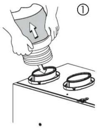
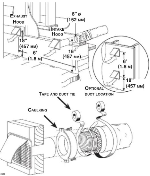
5.4.1 INSULATED FLEXIBLE DUCTS
- Pull back the insulation to expose the flexible 6 in. round duct.
- Attach the flexible duct to the port using tie wrap.
- Pull the insulation over the joint and tuck in between the inner and outer rings of the double collar without compressing it to minimize possible condensation buildup within the duct, as well as minimize building heat loss and gain.
- Pull down the vapor barrier (shaded part in illustrations below) over the outer ring to cover it completely. Fasten in place the vapor barrier using the port strap (included in unit parts bag). To do so, insert one collar pin through the vapor barrier and first strap hole, then insert the other collar pin through the vapor barrier and center strap hole and close the loop by inserting the first collar pin in the last strap hole to create an air-tight path and to minimize building heat loss and gain and reduce the potential for condensation.
natural_image
Illustration of hands using a tool to press or install a component on a gas stove (no text or symbols present)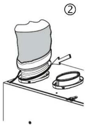
natural_image
Technical line drawing of a mechanical assembly with a base plate and clamped components (no text or symbols)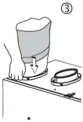
natural_image
Illustration of a hand using a tool to press or install a container on a table, with a magnified inset showing the same object (no text or symbols present)
text_image
COLLAR PINS ④ STRAPVJ0132
5.4.2 NON-INSULATED FLEXIBLE DUCTS
Use tie wraps to perform connections, then seal with duct tape.
5.4.3 NON-INSULATED RIGID DUCTS
To avoid transmission of vibrations, always use a 6-inch section of flexible duct to connect rigid ducts to the unit. Use tie wraps to perform connections, then seal with duct tape.
CAUTION
Make sure to replace insulation around any openings made in the building envelope when installing unit or ducting. Seal insulation with tape or caulk to minimize building heat loss and gain and to reduce the potential for condensation.
For the Installer
5.5 INSTALLING THE EXTERIOR HOODS
Refer to illustration at right to connect the insulated duct to the hoods. An “Anti-Gust Intake Hood” should be installed in regions where a lot of snow is expected to fall.
WARNING
Make sure that both hoods are at least 18 inches above the ground and that the intake hood is at least 6 feet (1.8 m) away from any of the following:
- Exhaust hood
- Dryer exhaust, high efficiency furnace vent, central vacuum vent
• Gas meter exhaust, gas barbecue-grill - Any exhaust from a combustion source
- Garbage bin and any other source of contamination
text_image
EXHAUST HOOD 6" Ø (152 MM) INTAKE HOOD 18" (457 MM) 6' (1.8 M) 18" (457 MM) 6' (1.8 M) 18" (457 MM) TAPE AND DUCT TIE CAULKING OPTIONAL DUCT LOCATION 00395.6 CONNECTING THE DRAIN
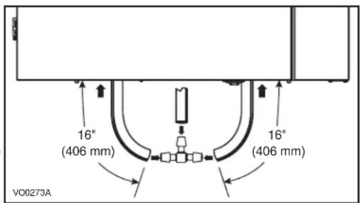
CAUTION
A drain tubing (included) must be installed for all HRV units. It is not required for ERV units, however, it is recommended in climates where the outdoor temperature can remain below -25^ (-13°F) over a 24-hour period for several days in a row, combined with an indoor humidity of 40% or higher.
- Cut 2 sections of plastic tubing of at least 16" each.
- Connect each one of them to the drain fittings located under the unit. If installing a drain on an ERV unit, remove both drain plugs inside the unit before installing the tubing.
- Join their other ends to the «T» junction and remaining tubing as illustrated. This will prevent the unit from drawing unpleasant odors from the drain source.
- Run the tube to the floor drain or to an alternative drain pipe or pail. If using a pail to collect water, locate the tube end approximately 1" into the pail in order to prevent water from being drawn back into the unit.
text_image
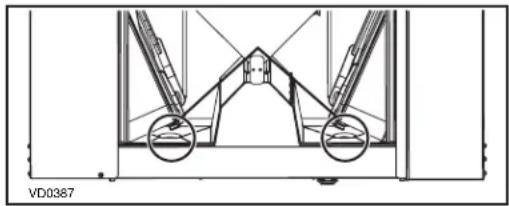
16" (406 mm) 16" (406 mm) VO0273ALOCATION OF THE DRAIN PLUGS ON ERV UNITS
natural_image
Technical line drawing of a mechanical structure with two circular components and connecting rods (no text or symbols)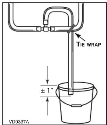
text_image
TIE WRAP ± 1" VD0337A6. WALL CONTROLS
WARNING
Always disconnect the unit before making any connections. Failure to disconnect power could result in electric shock or damage to the wall control or electronic module inside the unit.
CAUTION
Failure to comply with the following can cause erratic operation of the unit and/or the wall control:
Never install more than one main wall control per unit. Make sure that the wires do not short-circuit between themselves or by touching any other components on the wall control. Avoid poor wiring connections. To reduce electrical interference (noise) potential, do not run wall control wiring next to control contactors or near light dimming circuits, electrical motors, dwelling/building power or lighting wiring, or power distribution panel.
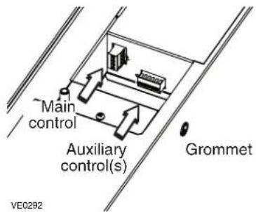
The terminal blocks needed to connect the wall controls are already installed on the electronic board. To access them, open the unit's side panel and remove the terminal blocks from the electronic board.
Run the wall control wires through the grommet before connecting them to the terminal blocks.
text_image
Main control Auxiliary control(s) Grommet VE02926.1 AUXILIARY WALL CONTROLS
Up to 5 20/40/60-minute auxiliary wall controls can be installed with this unit.
text_image
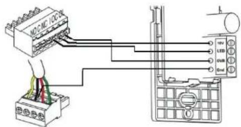
NO.CNC 100Ω TV LED GVB GNDNOTE: The auxiliary wall control can be used with a 3-wire connection by removing the LED signals. This optional wiring will not allow an installation with more than 1 auxiliary wall control to properly synchronize their LEDs on an event requested from a peer. Only the auxiliary wall control having requested the timer event will have the LEDs updated accordingly.
VC0237
Proceed as follows to connect the auxiliary wall control cable(s) to the 6-position terminal block:
- Strip the end of the cable.
- Strip 1/4" off the end of 3 of the wires.
- Insert the wires in their corresponding holes. A wire is correctly inserted when its orange receptacle is lower than another one without wire. On illustration below, wire A is correctly inserted, but wire B is not.
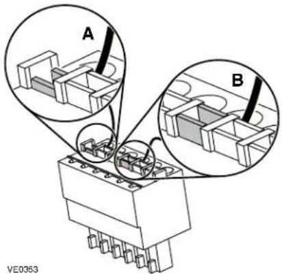
text_image
A B VE0363- Reinstall the terminal block on the electronic board.
- Refer to the controls' installation sheet for information on how to operate them.
For the Installer
6.2 MAIN WALL CONTROL
The only main wall controls compatible with these units are the X-Touch and Gold-Touch. Only one main wall control can be installed for each unit.
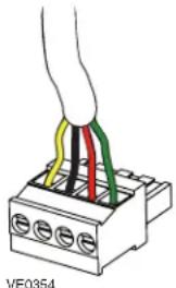
Proceed as follows to connect the main wall control cable to the 4-position terminal block:
- Strip the end of the cable.
- Strip 1/4" off the end of the 4 wires. Do not strip longer than required.
- Using a small flat blade screwdriver, connect each wire to its corresponding terminal by referring to the labels on the unit (YELLOW to Y; BLACK to B; RED to R; GREEN to G).
- Reinstall the terminal block on the electronic board.
- Refer to the controls' installation sheet for information on how to operate it.
natural_image
Diagram of a hand connecting three colored wires to a terminal block (no text or symbols)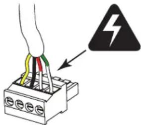
text_image
Diagram showing a cable connector with colored wires and a warning symbol indicating electrical hazard.7. ELECTRICAL CONNECTION TO THE FURNACE
WARNING
Never connect a 120-volt AC circuit to the terminals of the furnace interlock (standard wiring). Only use the low voltage class 2 circuit of the furnace blower control.
For a furnace connected to a cooling system:
On some older thermostats, energizing the "R" and "G" terminals at the furnace has the effect of energizing "Y" at the thermostat and thereby turning on the cooling system. If you identify this type of thermostat, you must use the ALTERNATE FURNACE INTERLOCK WIRING.
STANDARD FURNACE INTERLOCK WIRING
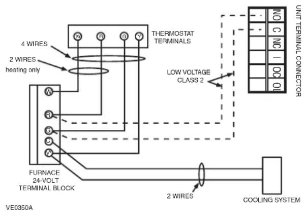
text_image
4 WIRE 2 WIRE heating only THERMOSTAT TERMINALS LOW VOLTAGE CLASS 2 FURNACE 24-VOLT TERMINAL BLOCK VE0350A 2 WIRE COOLING SYSTEM UNIT TERMINAL CONNECTORALTERNATE FURNACE INTERLOCK WIRING
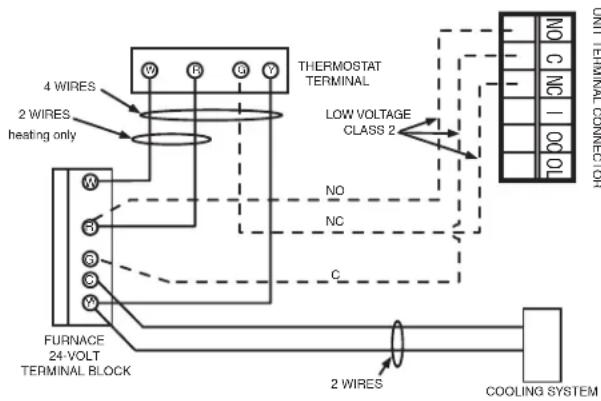
text_image
4 WIRE 2 WIRE heating only W R G Y THERMOSTAT TERMINAL LOW VOLTAGE CLASS 2 NO NC C FURNACE 24-VOLT TERMINAL BLOCK 2 WIRE COOLING SYSTEM UNIT TERMINAL CONNECTOR8. RECIRCULATION AND DEFROST SETTINGS
CAUTION
Set extended defrost on all units located in climates where the outdoor temperature typically remains below -25°C (-13°F) (i.e. Winnipeg, Regina, Quebec, Edmonton, Yellowknife, Whitehorse, Labrador City) over a 24-hour period for several days in a row, combined with an indoor humidity of 40% or higher.
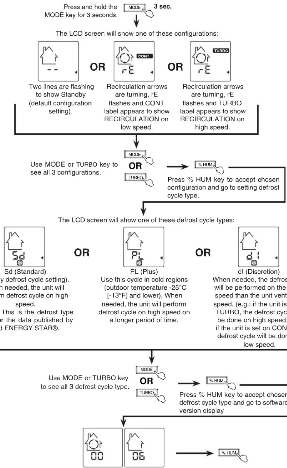
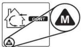
flowchart
graph TD
    A["Press and hold the MODE key for 3 seconds."] --> B["The LCD screen will show one of these configurations:"]
    B --> C["Two lines are flashing to show Standby (default configuration setting)."]
    B --> D["Recirculation arrows are turning, rE flashes and CONT label appears to show RECIRCULATION on low speed."]
    B --> E["Recirculation arrows are turning, rE flashes and TURBO label appears to show RECIRCULATION on high speed."]
    C --> F["Use MODE or TURBO key to see all 3 configurations."]
    D --> F
    E --> F
    F --> G["OR"]
    G --> H["Press % HUM key to accept chosen configuration and go to setting defrost cycle type."]
    H --> I["The LCD screen will show one of these defrost cycle types:"]
    I --> J["Sd (Standard) by defrost cycle setting. In needed, the unit will form defrost cycle on high speed. This is the defrost type for the data published by ENERGY STAR®."]
    I --> K["OR"]
    K --> L["Use this cycle in cold regions (outdoor temperature -25°C [-13°F"] and lower). When needed, the unit will perform defrost cycle on high speed on a longer period of time.]
    I --> M["OR"]
    M --> N["dI (Discretion) When needed, the defrost will be performed on the speed than the unit vent speed. (e.g.: if the unit is TURBO, the defrost cycle be done on high speed, if the unit is set on CON defrost cycle will be done low speed.)"]
    I --> O["OR"]
    O --> P["Use MODE or TURBO key to see all 3 defrost cycle type."]
    P --> Q["TURBO"]
    P --> R["% HUM"]
    R --> S["Press % HUM key to accept chosen defrost cycle type and go to software version display"]
    P --> T["% HUM"]
LCD screen alternates between the house with circled arrows and the house without arrow. The numbers under the house are the software version number.
Press % HUM key OR wait 10 seconds to exit user setting menu.
9.1 BEFORE STARTING
What you need to balance the Unit:
• One X-Touch / Gold-Touch main wall control close to the unit.
- A magnehelic gauge capable of measuring 0 to 1 inch of water (0 to 250 Pa) and 2 plastic tubes.
- The balancing chart and preset speeds table of the unit; affixed on the unit, behind the small control panel.
Before balancing the unit:
- Seal all the unit ductwork with tape. Close all windows and doors.
- Turn off all exhaust devices such as range hood, dryer and bathroom fans.
- Make sure all filters are clean (if it is not the first time the unit is balanced).
NOTE: Make sure that the furnace/air handler blower is ON if the installation is in any way connected to the ductwork of the cold air return. If not, leave furnace/air handler blower OFF.
Installing the magnehelic gauge:
- Place the magnehelic gauge on a level surface and adjust it to zero.
- According to the airflow to be measured, connect tubing from gauge to STALE air flow or FRESH air flow pressure taps (see illustration at right).
- Be sure to connect the tubes to their appropriate high/low fittings. If the gauge drops below zero, reverse the tubing connections.
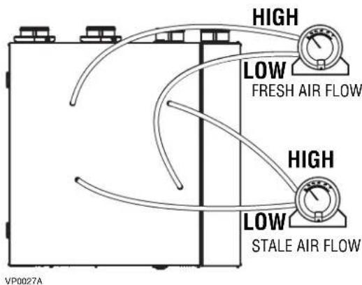
text_image
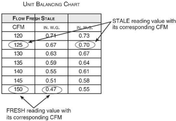
HIGH LOW FRESH AIR FLOW HIGH LOW STALE AIR FLOW VP0027ABalancing Chart and Preset Speeds Table
Use the balancing chart on the unit to convert pressure (in. w.g.) values read by the magnehelic gauge to airflow (CFM) values. While balancing, the X-Touch/Gold-Touch wall control screen shows which pressure taps have to be used. Keep in mind that a difference between flows up to ±10 cfm is acceptable. See example below.
Plug magnehelic gauge tubing to STALE airflow.
Plug magnehelic gauge tubing to FRESH airflow.
other
UNIT BALANCING CHART | Category | FRESH reading value with its corresponding CFM | STALE reading value with its corresponding CFM | |---|---|---| | CFM | IN.W.G. | IN.W.G. | | 120 | 0.71 | 0.73 | | 125 | 0.67 | 0.70 | | 130 | 0.63 | 0.67 | | 135 | 0.59 | 0.64 | | 140 | 0.55 | 0.61 | | 145 | 0.51 | 0.58 | | 150 | 0.47 | 0.55 | FRESH reading value with its corresponding CFMFor the Installer
9.2 BALANCING THE UNIT
① Connect an X-Touch/Gold-Touch main wall control to the unit. The control has to be close to the unit.
GENERAL INFORMATION ABOUT X-TOUCH/GOLD-TOUCH WALL CONTROL USAGE IN UNIT BALANCING PROCEDURE
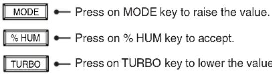
text_image
MODE •— Press on MODE key to raise the value. % HUM •— Press on % HUM key to accept. TURBO •— Press on TURBO key to lower the value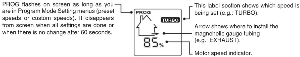
text_image
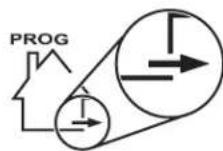
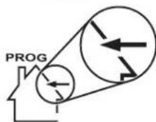
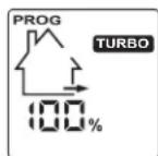
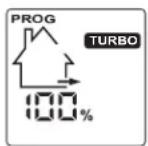
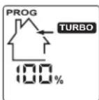
PROG flashes on screen as long as you are in Program Mode Setting menus (preset speeds or custom speeds). It disappears from screen when all settings are done or when there is no change after 60 seconds. This label section shows which speed is being set (e.g.: TURBO). Arrow shows where to install the magnehelic gauge tubing (e.g.: EXHAUST). Motor speed indicator.② Enter Program Mode.
flowchart
graph LR
    A["% HUM"] --> B["AND"]
    C["TURBO"] --> B
    B --> D["PROG Mode"]
    D --> E["MODE OR % HUM TURBO"]
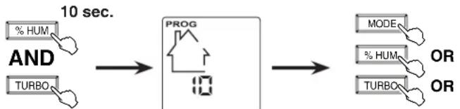
Press and hold both % HUM and TURBO keys for 10 seconds.
PROG start flashing. A 10-second countdown appears.
Press any key to enter program mode. If there is no key pressed before the end of the countdown, the unit will go back to its previous mode.
Choose between two options: • 01, 02, etc.: Preset speeds (balance the unit only, faster option)
- __: Custom speeds (adjust TURBO speed and balance the unit, then set CONT, 20/40/60 min. control and RECIRC speeds).
③ Select the Preset speeds or Custom speeds.
flowchart
graph LR
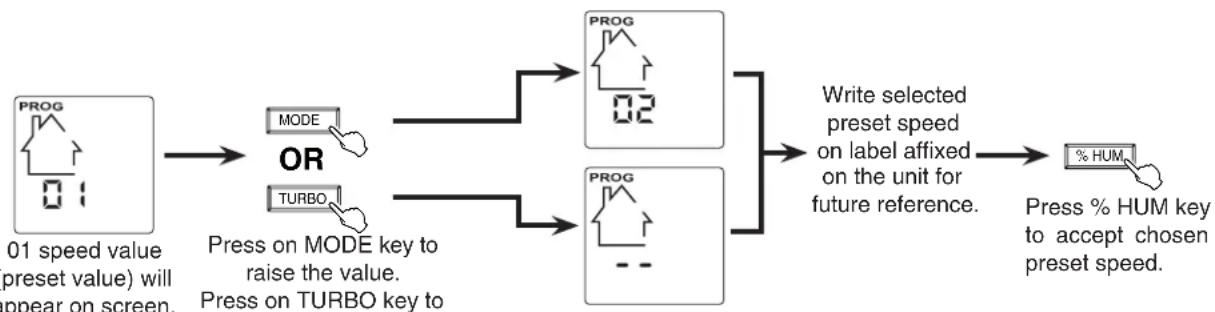
A["PROG 01 speed value (preset value) will appear on screen."] --> B["MODE"]
A --> C["TURBO"]
B --> D["OR"]
C --> D
D --> E["PROG 02"]
D --> F["PROG --"]
E --> G["Write selected preset speed on label affixed on the unit for future reference."]
F --> G
G --> H["% HUM"]
H --> I["Press % HUM key to accept chosen preset speed."]
NOTE: From 01 value, pressing on TURBO key will access to custom speed settings (see page 19).
④ Connect the magnehelic tubings to the unit (see 9.1).
For the Installer
⑤ If the unit speed is set close to its highest speed, we recommend to first measure and note both airflows.
⑥ Refer to the unit balancing chart to find the corresponding CFMs.
⑦ Determine which airflow should be adjusted (the higher airflow must be lowered to equalize the lower one). See example below.
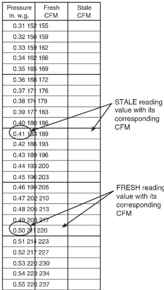
other
| Pressure in. w.g. | Fresh CFM | Stale CFM | |---|---|---| | 0.31 152 155 | | | | 0.32 156 159 | | | | 0.33 159 162 | | | | 0.34 162 166 | | | | 0.35 165 169 | | | | 0.36 168 172 | | | | 0.37 171 176 | | | | 0.38 174 179 | | | | 0.39 177 183 | | | | 0.40 180 186 | | | | 0.41 183 189 | | | | 0.42 186 193 | | | | 0.43 189 196 | | | | 0.44 193 200 | | | | 0.45 196 203 | | | | 0.46 199 206 | | | | 0.47 202 210 | | | | 0.48 205 213 | | | | 0.49 208 217 | | | | 0.50 211 220 | | | | 0.51 214 223 | | | | 0.52 217 227 | | | | 0.53 220 230 | | | | 0.54 223 234 | | | | 0.55 226 237 | | | STALE reading value with its corresponding CFM FRESH reading value with its corresponding CFMNOTE: At first airflow readings, for speed value 01, both stale and fresh airflow values displayed on control screen are 100%.
Before airflow adjustment
STALE airflow reading:
0.41 in. w.g., 189 CFM
FRESH airflow reading:
0.50 in. w.g., 211 CFM
After airflow adjustment
STALE airflow reading:
0.41 in. w.g., 189 CFM
FRESH airflow reading:
0.43 in. w.g., 189 CFM
In that case, the FRESH airflow must be lowered to reach the STALE airflow value.
⑧ Adjust stale air TURBO speed (or press % HUM key to keep it as is).
NOTE: The following shown values are example. The real values vary according to the preset speed chosen, the unit installation, etc.
Take the reading from stale airflow pressure taps.
Press on MODE key to raise the value.
Press on TURBO key to lower the value.
flowchart
graph TD
    A["Start"] --> B["PROG TURBO 85%"]
    C["Start"] --> D["PROG TURBO 84%"]
    B --> E["Output"]
    D --> E
Write selected airflow percentage on label affixed on the unit for future reference.
Press % HUM key to accept chosen percentage.
Check the magnehelic gauge along with the unit balancing chart until the desired airflow is reached.
For the Installer
⑨ Adjust fresh air TURBO speed (or press % HUM key to keep it as is).
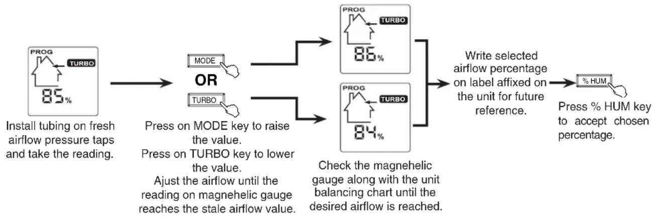
flowchart
graph LR
    A["PROG TURBO 85%"] --> B["MODE"]
    A --> C["TURBO"]
    B --> D["PROG TURBO 86%"]
    C --> E["PROG TURBO 84%"]
    D --> F["Write selected airflow percentage on label affixed on the unit for future reference."]
    E --> F
    F --> G["% HUM"]
    style A fill:#f9f,stroke:#333
    style G fill:#ccf,stroke:#333
If you have selected the preset speed balancing at ②, the balancing procedure is completed.
If you have selected the custom speed balancing, continue with the following:
⑩ Set CONT speed.
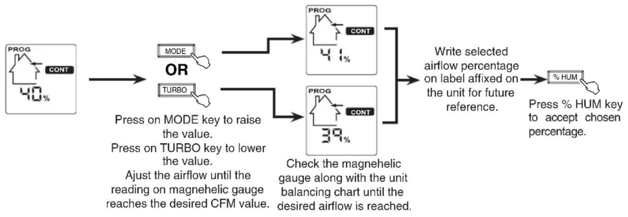
flowchart
graph TD
    A["PROG CONT 40%"] --> B["MODE"]
    A --> C["TURBO"]
    B --> D["PROG CONT 41%"]
    C --> E["PROG CONT 39%"]
    D --> F["Write selected airflow percentage on label affixed on the unit for future reference."]
    E --> F
    F --> G["% HUM"]
    G --> H["Press % HUM key to accept chosen percentage."]
    style A fill:#f9f,stroke:#333
    style B fill:#ccf,stroke:#333
    style C fill:#ccf,stroke:#333
    style D fill:#cfc,stroke:#333
    style E fill:#cfc,stroke:#333
    style F fill:#fcc,stroke:#333
    style G fill:#fcc,stroke:#333
    style H fill:#fcc,stroke:#333
For the Installer
⑪ Set 20/40/60-minute control speed.
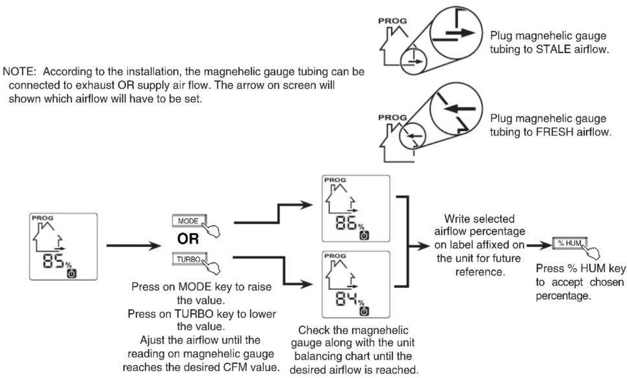
flowchart
graph TD
    A["PROG 85%"] --> B["MODE"]
    A --> C["TURBO"]
    B --> D["OR"]
    C --> D
    D --> E["PROG 86%"]
    D --> F["PROG 84%"]
    E --> G["Write selected airflow percentage on label affixed on the unit for future reference."]
    F --> G
    G --> H["% HUM"]
    H --> I["Press % HUM key to accept chosen percentage."]
⑫ Set RECIRC speed.
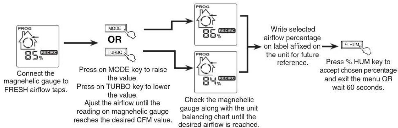
flowchart
graph TD
    A["PROG 85% RECIRC"] --> B["OR"]
    B --> C["MODE"]
    B --> D["TURBO"]
    C --> E["PROG 86% RECIRC"]
    D --> F["PROG 84% RECIRC"]
    E --> G["Write selected airflow percentage on label affixed on the unit for future reference."]
    F --> G
    G --> H["% HUM"]
    I["Connect the magnehelic gauge to FRESH airflow taps."] --> B
    J["Press on MODE key to raise the value.<br>Press on TURBO key to lower the value.<br>Ajust the airflow until the reading on magnehelic gauge reaches the desired CFM value."] --> B
    K["Check the magnehelic gauge along with the unit balancing chart until the desired airflow is reached."] --> F
    L["Press % HUM key to accept chosen percentage and exit the menu OR wait 60 seconds."] --> H
The balancing procedure is completed.
The adjusted airflow values are stored in the unit. If needed, any X-Touch/Gold-Touch main control can be used to adjust the unit speeds and balance the unit again. If a power failure occurs, the unit will keep these setting values in memory. To change the setting values, go to step ⑥ and follow the procedure, the new values will replace the previous ones.
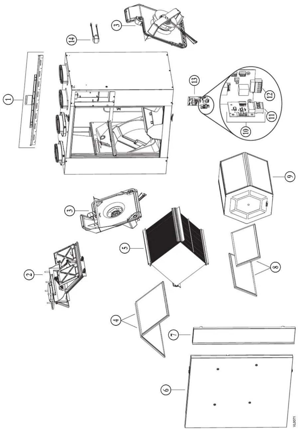
text_image
Exploded view diagram of a device with numbered parts for identification and assembly reference.| No. | DESCRIPTION QTY. | X24 ERV ECM | X24 HRV ECM | X30 ERV ECM | X30 HRV ECM | X24 ERV ECM-N | X24 HRV ECM-N | X30 ERV ECM-N | X30 HRV ECM-N | G2400E ECM | G2400H ECM | G3000E ECM | G3000H ECM | |
| 1 | BRACKET KIT | 1 | 63419 | 63419 | 63419 | 63419 | 63419 | 63419 | 63419 | 63419 | 63419 | 63419 | 63419 | 63419 |
| 2 | DAMPER SYSTEM ASSEMBLY (INCLUDING 2 PLASTIC SCREWS) | 1 63 | 420 634 | 20 634 | 20 6342 | 0 63420 | 63420 634 | 20 63420 | 63420 63420 | 63420 63420 | 420 | |||
| 3 | BLOWER ASSEMBLY (INCLUDING 3 PLASTIC SCREWS) | 2 63 | 421 634 | 21 634 | 21 6342 | 1 63421 | 63421 634 | 21 63421 | 63421 63421 | 63421 63421 | 421 | |||
| 4 | HRV CORE FILTER (PAIR) | 1 | 63426 | 63426 | 63426 | 63426 | 63426 | 63426 | ||||||
| ERV CORE FILTER (PAIR) | 1 | 63433 | 63433 | 63433 | ||||||||||
| 5 | HEAT RECOVERY CORE | 1 | 63422 | 63423 | 63422 | 63423 | 63422 | 63423 | ||||||
| ENERGY RECOVERY CORE | 1 | 63425 | 63425 | 63425 | ||||||||||
| 6 | DOOR ASSEMBLY (INCLUDING NO. 16) | 1 63 | 429 634 | 29 634 | 29 6342 | 9 63429 | 63429 634 | 29 63429 | 63428 63428 | 63428 63428 | 428 | |||
| 7 | RIGHT PANEL | 1 | 63432 | 62495 | 62498 | 62499 | 63432 | 62495 | 62498 | 62499 | 63430 | 62500 | 62502 | 62504 |
| 8 | ERV CORE FILTER (PAIR) | 1 | 63427 | 63427 | 63427 | |||||||||
| 9 | ENERGY RECOVERY CORE | 1 | 63424 | 63424 | 63424 | |||||||||
| 10 | DAUGHTER BOARD (INCLUDING INO. 11) | 1 63 | 437 634 | 37 634 | 37 6343 | 7 63437 | 63437 634 | 37 63437 | 63437 63437 | 63437 63437 | 437 | |||
| 11 | PCB CONNECTOR (MAIN CONTROL) | 1 63 | 434 634 | 34 634 | 34 6343 | 4 63434 | 63434 634 | 34 63434 | 63434 63434 | 63434 63434 | 434 | |||
| 12 | PCB CONNECTOR (AUXILIARY CONTROL) | 1 63 | 435 634 | 35 634 | 35 6343 | 5 63435 | 63435 634 | 35 63435 | 63435 63435 | 63435 63435 | 435 | |||
| 13 | PCB (INCLUDING NOS. 10 &12) | 1 | 63436 | 63441 | 63442 | 63443 | SV64392 | SV64393 | SV64394 | SV64395 | 63436 | 63441 | 63442 | 63443 |
| 14 | TRANSFORMER | 1 | 63438 | 63438 | 63438 | 63438 | 63438 | 63438 | 63438 | 63438 | 63438 | 63438 | 63438 | 63438 |
| * | WARM SIDE THERMISTOR KIT | 1 | 62481 | 62481 | 62481 | 62481 | 62481 | 62481 | 62481 | 62481 | 62481 | 62481 | 62481 | 62481 |
| * | DOOR MAGNETIC SWITCH | 1 | 19060 | 19060 | 19060 | 19060 | 19060 | 19060 | 19060 | 19060 | 19060 | 19060 | 19060 | 19060 |
| * | PLASTIC SCREW (SET OF 6) | 1 | 63439 | 63439 | 63439 | 63439 | 63439 | 63439 | 63439 | 63439 | 63439 | 63439 | 63439 | 63439 |
| * | HARDWARE KIT | 1 | 22488 | 22488 | 22488 | 22488 | 22488 | 22488 | 22488 | 22488 | 22488 | 22488 | 22488 | 22488 |
* Not shown.
In order to ensure your ventilation unit remains in good working condition, you must use the manufacturer genuine replacement parts only. The manufacturer genuine replacement parts are specially designed for each unit and are manufactured to comply with all the applicable certification standards and maintain a high standard of safety. Any third party replacement part used may cause serious damage and drastically reduce the performance level of your unit, which will result in premature failing. The manufacturer recommends to contact a certified service depot for all replacement parts and repairs.
REPLACEMENT PARTS AND REPAIR
11. WIRING DIAGRAM
WARNING
- Risk of electric shocks. Before performing any maintenance or servicing, always disconnect the unit from its power source.
- This product is equipped with an overload protection (fuse). A blown fuse indicates an overload or a short-circuit situation. If the fuse blows, unplug the product from the outlet. Discontinue using the unit and contact technical support.
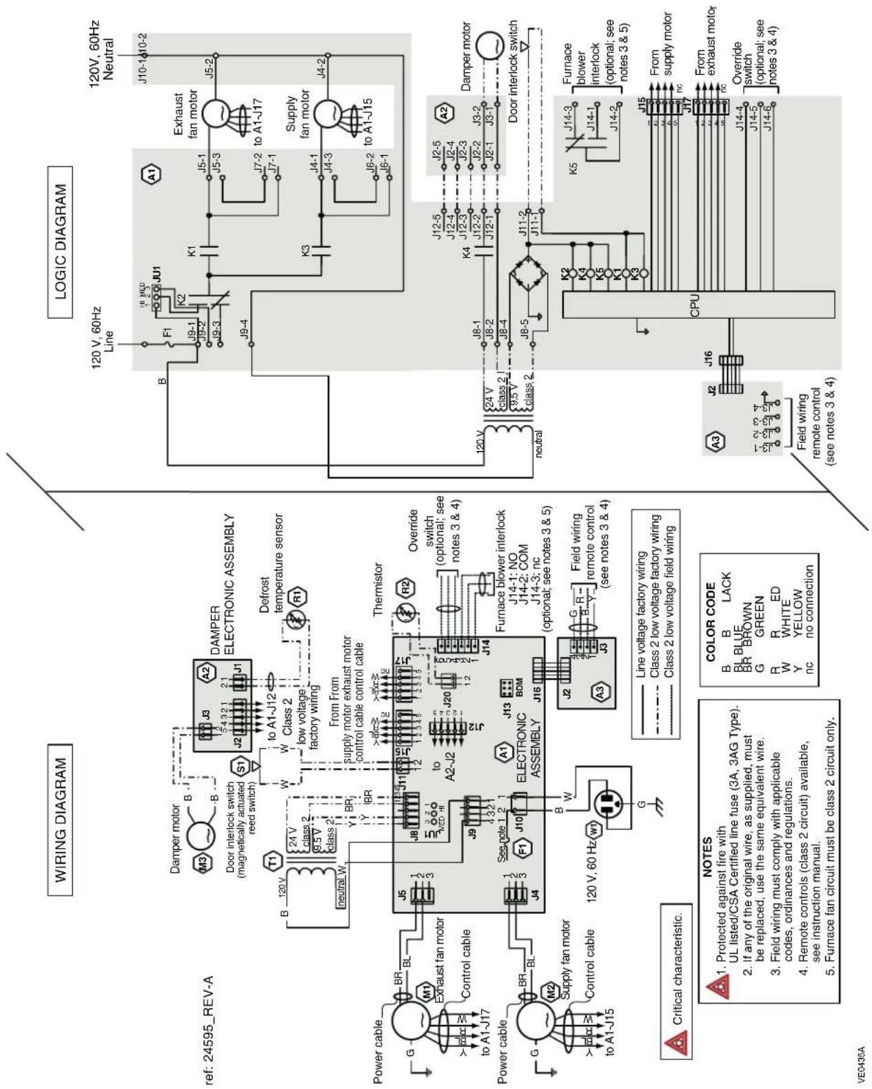
text_image
WIRING DIAGRAM ref: 24595_REV-A Damper motor M3 Door interlock switch (magnetically actuated reed switch) S1 J2 A2 DAMPER ELECTRONIC ASSEMBLY to A1-J12 Class 2 low voltage factory wiring R1 Defrost temperature sensor T1 120 V neutral W 24 V t class 2 8.5 V class 2 From From supply motor exhaust motor control cable control cable J5 J8 J11 J12 J13 J14 J15 J16 J17 J18 J19 J20 J21 J22 J23 J24 J25 J26 J27 J28 J29 J30 J31 J32 J33 J34 J35 J36 J37 J38 J39 J40 J41 J42 J43 J44 J45 J46 J47 J48 J49 J50 J51 J52 J53 J54 J55 J56 J57 J58 J59 J60 J61 J62 J63 J64 J65 J66 J67 J68 J69 J70 J71 J72 J73 J74 J75 J76 J77 J78 J79 J80 J81 J82 J83 J84 J85 J86 J87 J88 J89 J90 J91 J92 J93 J94 J95 J96 J97 J98 J99 J100-14-10-2 Line HLD JU1 A1 Exhaust fan motor J5-2 J5-1 to A1-J17 Supply fan motor J4-2 J4-1 to A1-J15 J6-2 to A1-J15 J4-2 J4-1 to A1-J15 J6-1 J6-1 J6-1 J6-1 J6-1 J6-1 J6-1 J6-1 J6-1 J6-1 J6-1 J6-1 J6-1 J6-1 J6-1 J6-1 J6-1 J6-1 J6-1 J6-1 J6-1 J6-1 J6-1 J6-1 J6-1 J6-2 J4-2 J4-2 J4-2 J4-2 J4-2 J4-2 J4-2 J4-2 J4-2 J4-2 J4-2 J4-2 J4-2 J4-2 J4-2 J4-2 J4-2 J4-2 J4-2 J4-2 J4-2 J4-2 J4-2 J4-2 J4-2 J3-2 Dampere motor Door interlock switch A2 Furnace blower interlock (optional; see notes 3 & 5) J12-5 J2-5 A2 J12-4 J2-4 A2 J12-3 J2-3 A2 J12-2 J2-2 A2 J12-1 CPM CPU K5 K4 K3 K2 K1 K0 K0 K0 K0 K0 K0 K0 K0 K0 K0 K0 K0 K0 K0 K0 K0 K0 K0 K0 K0 K0 K0 K0 K0 K0 K0 K0 K0 K0 K0 K0 K0 K0 K0 K0 K0 K0 K0 K0 K0 K0 K0 K0 K0 K0 K0 K0 K0 K0 K0 K5 F1 F2 F3 F4 F5 F6 F7 F8 F9 F10 F11 F12 F13 F14 F15 F16 F17 F18 F19 F20 F21 F22 F23 F24 F25 F26 F27 F28 F29 F30 F31 F32 F33 F34 F35 F36 F37 F38 F39 F40 F41 F42 F43 F44 F45 F46 F47 F48 F49 F50 F51 F52 F53 F54 F55 F56 F57 F58 F59 F60 F61 F62 F63 F64 F65 F66 F67 F68 F69 F70 F71 F72 F73 F74 F75 F76 F77 F78 F79 F80 F81 F82 F83 F84 F85 F86 F87 F88 F89 F90 F91 F92 F93 F94 F95 F96 F97 F98 F99 G B LACK BL BLUE BR BROWN G GREEN R R ED W WHITE Y YELLOW nc no connection NO NOT TO NOT NOT NOT NOT NOT NOT NOT NOT NOT NOT NOT NOT NOT NOT NOT NOT NOT NOT NOT NOT NOT NOT NOT NOT NOT NOT NOT NOT NOT NOT NOT NOT NOT NOT NOT NOT NOT NOT NOT NOT NOT NOT NOT NOT NOT NOT NOT NOT NOT NOT NOT NOT NOT NOT NOT NOT NOT NOT NOT NOT NOT NOT NOT NOT NOT NOT NOT NOT NOT NOT NOT NOT NOT NOT NOT NOT NOT NOT NOT NOT NOT NOT NOT NOT NOT NOT NOT NOT NOT NOT NOT NOT NOT NOT NOT NOT NOT NOT NOT NOTNOT IN THIS PROCEDURE OF THE PROCEDURE OF THE PROCEDURE OF THE PROCEDURE OF THE PROCEDURE OF THE PROCEDURE OF THE PROCEDURE OF THE PROCEDURE OF THE PROCEDURE OF THE PROCEDURE OF THE PROCEDURE OF THE PROCEDURE OF THE PROCEDURE OF THE PROCEDURE OF THE PROCEDURE OF THE PROCEDURE OF THE PROCEDURE OF THE PROCEDURE OF THE PROCEDURE OF THE PROCEDURE OF THE PROCEDURE OF THE PROCEDURE OF THE PROCEDURE OF THE PROCEDURE OF THE PROCEDURE OF THE PROCEDURE OF THEY#N##N##N##N##N##N##N##N##N##N##N##N##N##N##N##N##N##N##N##N##N##N##N##N##N##N##N##N##N##N##N##N##N##N##N##N##N##N##N##N##N##N##N##N##N##N##N##N##N##N##N### N### N### N### N### N### N### N### N### N### N### N### N### N### N### N### N### N### N### N### N### N### N### N### N### N### N### N### N### N### N### N### N### N### N### N### N### N### N### N### N### N### N### N### N### N### N### N### N### N### N###N#### N#### N#### N#### N#### N#### N#### N#### N#### N#### N#### N#### N#### N#### N#### N#### N#### N#### N#### N#### N#### N#### N#### N#### N#### N#### N#### N#### N#### N#### N#### N#### N#### N#### N#### N#### N#### N#### N#### N#### N#### N#### N#### N#### N#### N#### N#### N#### N#### N#### N####N#### NO Not Not Not Not Not Not Not Not Not Not Not Not Not Not Not Not Not Not Not Not Not Not Not Not Not Not Not Not Not Not Not Not Not Not Not Not Not Not Not Not Not Not Not Not Not Not Not Not Not Not Not Not Not Not Not Not Not Not Not Not Not Not Not Not Not Not Not Not Not Not Not Not Not Not Not Not Not Not Not Not Not Not Not Not Not Not Not Not Not Not Not Not Not Not Not Not Not Not Not NotNot In This Procedure is not in this procedure. The following instructions are not in this procedure. The following instructions must be classified as a class of 3 or 4 by the following instructions must be classified as a class of 3 or 4 by the following instructions must be classified as a class of 3 or 4 by the following instructions must be classified as a class of 3 or 4 by the following instructions must be classified as a class of 3 or 4 by the following instructions must be classified as a class of 3 or 4 by the following instructions must be classified as a class of 3 or 4 by the following instructions must have been replaced with the same equivalent wire. NOTE: Protected against fire with UL listed/CSA Certified line fuse (3A, 3AG Type). If any of the original wire, as supplied, must be replaced, use the same equivalent wire. Field wiring must comply with applicable codes, ordinances and regulations. Remote controls (class 2 circuit) available, see instruction manual. Furnace fan circuit must be class 2 circuit only. COLOR CODE B B LACK BL BLUE BR BROWN G GREEN R R ED W WHITE Y YELLOW nc no connection NO No Not Important Notes in this Procedure. Field wiring remote control (see notes 3 & 4). Field wiring winding remote control (see notes 3 & 4). Field wiring winding main switch to the main switch is not in this procedure. Field wiring switches to the main switch should be replaced with the same equivalent wire. Field wiring switches to the main switch should be replaced with the same equivalent wire. Field wiring switches to the main switch should be replaced with the same equivalent wire. Field wiring switches to the main switch should be replaced with the same equivalent wire. Field wiring switches to the main switch should be replaced with the same equivalent wire. Field wiring switches to the main switch should be replaced with the same equivalent wire. Field wiring switches to the main switch should be replaced with the same equivalent wire. Field wiring switches to other switches: No protection against fire with UL listed/CSA Certified line fuse (3A, 3AG Type). If any of the original wire, as supplied, must be replaced, use the same equivalent wire. Field wiring must comply with applicable codes, ordinances and regulations. Field wiring switches to the main switch should be replaced with the same equivalent wire. Field wiring switches to the main switch should be replaced with the same equivalent wire. Field wiring switches to other switches: No protection against fire with UL listed/CSA Certified line fuse (3A, 3AG Type). If any of the original wire, as supplied, must be replaced, use the same equivalent wire. Field wiring must comply with applicable codes, ordinances and regulations. Field wiring switches to other switches: No protection against fire with UL listed/CSA Certified line fuse (3A, 3AG Type). If any of the original wire, as supplied, must be replaced, use the same equivalent wire. Field wiring switches to other switches: No protection against fire with UL listed/CSA Certified line fuse (3A, 3AG Type). If any of the original wire, as supplied, must be replaced, use the same equivalent wire. Field wiring switches to other switches: No protection against fire with UL listed/CSA Certified line fuse (3A, 3AG Type). If any of the original wire, as supplied, must be replaced, use the same equivalent wires. Field wiring switches to other switches: No protection against fire with UL listed/CSA Certified line fuse (3A, 3AG Type). If any of the original wire, as supplied, must be replaced, use the same equivalent wires. Field wiring switches to other switches: No protection against fire with UL listed/CSA Certified line fuse (3A, 3AG Type). If any of the original wire, as supplied, must be replaced, use the same equivalent wire. Field wiring switches to other switches: No protection against fire with UL listed/CSA Certified line fuse (3A, 3AG Type). If any of the original wire, as supplied, must be replaced, use the same equivalent lines. Field wiring switches to other switches: No protection against fire with UL listed/CSA Certified line fuse (3A, 3AG Type). If any of the original wire, as supplied, must be replaced, use the same equivalent lines. Field wiring switches to other switches: No protection against fire with UL listed/CSA Certified line fuse (3A, 3AG Type). If any of the original wire, as supplied, must be replaced, use the same equivalent wire. Field wiring switches to other switches: No protection against fire with UL listed/CSA Certified line fuse (3A, 3AG Type). If any of the original wire, as supplied, must be replaced, use the same equivalent line. Field wiring switches to other switches: No protection against fire with UL listed/CSA Certified line fuse (3A, 3AG Type). If any of the original wire, as supplied, must be replaced, use the same equivalent wire. Field wiring switches to other switches: No protection against fire with UL listed/CSA Certified line fuse (3A, 3AG Type). If any of the original wire, as supplied, must be replaced, use the same equivalent wine. Field wiring switches to other switches: No protection against fire with UL listed/CSA Certified line fuse (3A, 3AG Type). If any of the original wire, as supplied, must be replaced, use the same equivalent wire. Field wiring switches to other switches: No protection against fire with UL listed/CSA Certified line fuse (3A, 3AG Type). Field wiring switches to other switches: No protection against fire with UL listed/CSA Certified line fuse (3A, 3AG Type). Field wiring switches to other switches: No protection against fire with UL listed/CSA Certified line fuse (3A, 3AG Type). Field wiring switches to other switches: No protection against fire with UL listed/CSA Certified line fuse (3A, 3AG Type). Field wiring switches to other switches: No protective against fire with UL listed/CSA Certified line fuse (3A, 3AG Type). If any of the original wire, as supplied, must be replaced, use the same equivalent wire. Field wiring switches to other switches: No protection against fire with UL listed/CSA Certified line fuse (3A, 3AG Type). Field wiring switches to other switches: No protection against fire with UL listed/CSA Certified line fuse (3A, 3AG Type) Field wiring switches to other switches: No protection against fire with UL listed/CSA Certified line fuse (3A, 3AG Type). Field wiring switches to other switches: No protection against fire with UL listed/CSA Certified line fuse (3A, 3AG Type). Field wiring switches to other switches: No protection against fire with UL listed/CSA Certified line fuse (3A, 3AG Type). Field wiring switches to other switches: No maintenance against fire against fire against fire against fire against fire against fire against fire against fire against fire against fire against fire against fire against fire against fire against fire against fire against fire against fire against fire against fire against fire against fire against fire against fire against fire against fire against fire against fire against fire against fire against fire against fire against fire against fire against fire against fire against fire against fire against fire against fire against fire against fire against fire against fire against fire against fire against fire against fire against fire versus their respective conditions. Critical characteristic.12. TROUBLESHOOTING
WARNING
Risk of electric shocks. Electronic board connections must be checked by qualified personnel only.
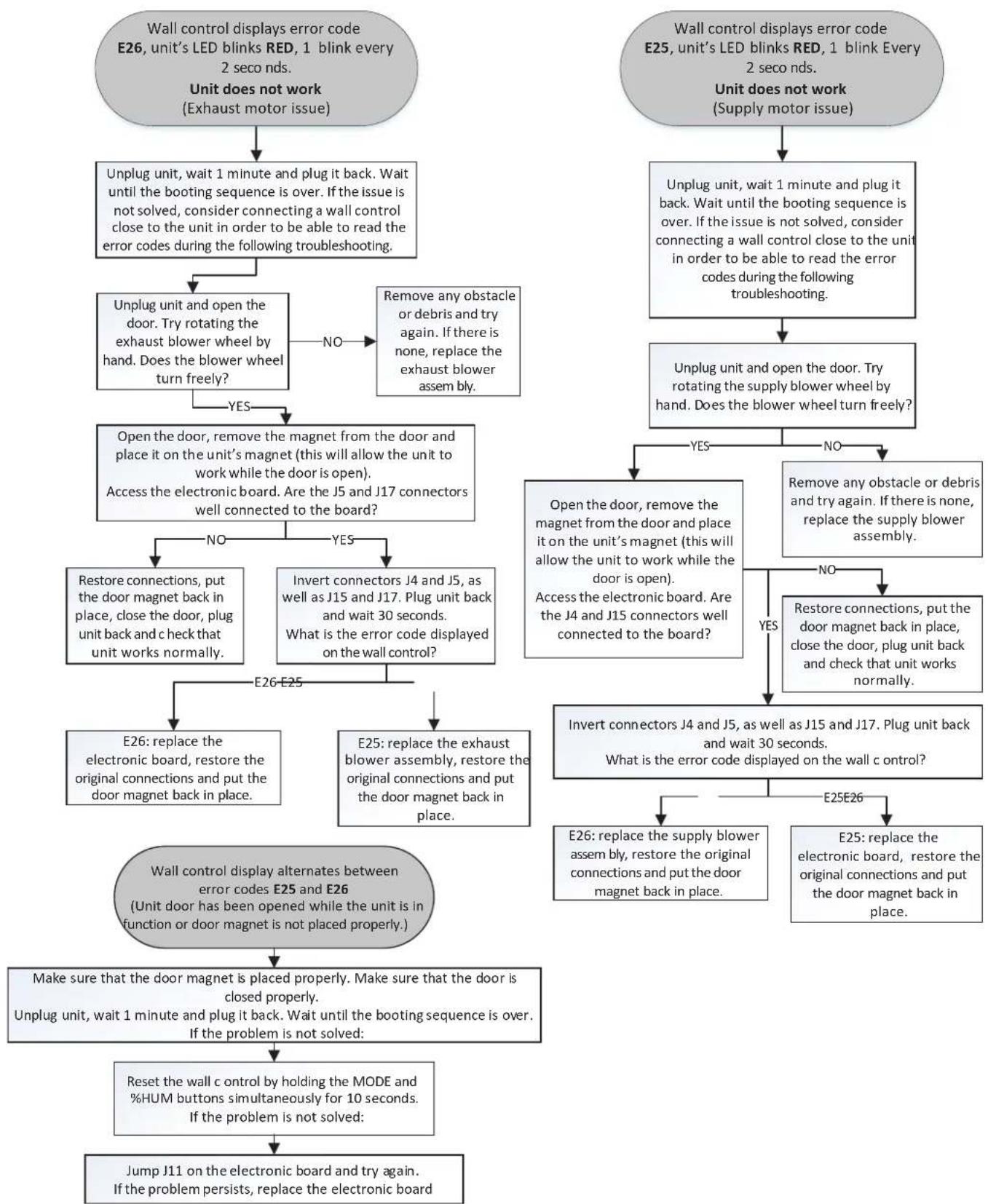
flowchart
graph TD
    A["Wall control displays error code E26, unit's LED blinks RED, 1 blink every 2 seconds.<br>Unit does not work (Exhaust motor issue)"] --> B["Unplug unit, wait 1 minute and plug it back. Wait until the booting sequence is over. If the issue is not solved, consider connecting a wall control close to the unit in order to be able to read the error codes during the following troubleshooting."] --> C["Unplug unit and open the door. Try rotating the exhaust blower wheel by hand. Does the blower wheel turn freely?"]
    C -->|NO| D["Remove any obstacle or debris and try again. If there is none, replace the exhaust blower assembly."]
    C -->|YES| E["Open the door, remove the magnet from the door and place it on the unit's magnet (this will allow the unit to work while the door is open). Access the electronic board. Are the J5 and J17 connectors well connected to the board?"]
    E -->|NO| F["Restore connections, put the door magnet back in place, close the door, plug unit back and check that unit works normally."]
    E -->|YES| G["Invert connectors J4 and J5, as well as J15 and J17. Plug unit back and wait 30 seconds. What is the error code displayed on the wall control?"]
    F --> H["E26: replace the electronic board, restore the original connections and put the door magnet back in place."]
    G --> I["E25: replace the exhaust blower assembly, restore the original connections and put the door magnet back in place."]
    D --> J["Unplug unit and open the door. Try rotating the supply blower wheel by hand. Does the blower wheel turn freely?"]
    J -->|YES| K["Open the door, remove the magnet from the door and place it on the unit's magnet (this will allow the unit to work while the door is open). Access the electronic board. Are the J4 and J15 connectors well connected to the board?"]
    J -->|NO| L["Remove any obstacle or debris and try again. If there is none, replace the supply blower assembly."]
    L --> M["Restore connections, put the door magnet back in place, close the door, plug unit back and check that unit works normally."]
    M --> N["Invert connectors J4 and J5, as well as J15 and J17. Plug unit back and wait 30 seconds.<br>What is the error code displayed on the wall c control?"]
    N --> O["E26: replace the supply blower assembly, restore the original connections and put the door magnet back in place."]
    N --> P["E25: replace the electronic board, restore the original connections and put the door magnet back in place."]
    O --> Q["Make sure that the door magnet is placed properly. Make sure that the door is closed properly.<br>Unplug unit, wait 1 minute and plug it back. Wait until the booting sequence is over. If the problem is not solved:"]
    P --> R["Reset the wall c control by holding the MODE and %HUM buttons simultaneously for 10 seconds.<br>If the problem is not solved:"]
    Q --> S["Jump J11 on the electronic board and try again.<br>If the problem persists, replace the electronic board"]
    R --> S
flowchart
graph TD
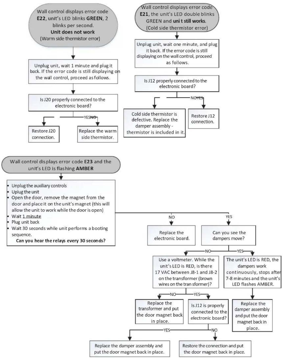
A["Wall control displays error code E22, unit's LED blinks GREEN, 2 blinks per second.<br>Unit does not work<br>(Warm side thermistor error)"] --> B["Unplug unit, wait 1 minute and plug it back. If the error code is still displaying on the wall control, proceed as follows."]
B --> C["Is J20 properly connected to the electronic board?"]
C --> D{Yes/No}
D -->|YES| E["Restore J20 connection."]
D -->|NO| F["Replace the warm side thermistor."]
G["Wall control displays error code E21, unit's LED double blinks GREEN and unit still works.<br>(Cold side thermistor error)"] --> H["Unplug unit, wait one minute, and plug it back. If the error code is still displaying on the wall control, proceed as follows."]
H --> I["Is J12 properly connected to the electronic board?"]
I --> J{NO YES}
J -->|YES| K["Cold side thermistor is defective. Replace the damper assembly - thermistor is included in it."]
J -->|NO YES| L["Restore J12 connection."]
M["Wall control displays error code E23 and the unit's LED is flashing AMBER"] --> N{No}
N --> O["Replace the electronic board."]
N --> P{YES}
O --> Q["Use a voltmeter. While the unit's LED is RED, is there 17 VAC between J8-1 and J8-2 on the transformer (brown wires on the tran sformer)?"]
P --> R{No}
R -->|YES| S["Replace the damper assembly and put the door magnet back in place."]
R --> T{NO}
S --> U["Replace the damper assembly and put the door magnet back in place."]
S --> V["Restore the connection and put the door magnet back in place."]
flowchart
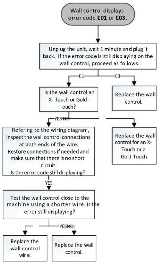
graph TD
    A["Wall control displays error code E01 or E03."] --> B["Unplug the unit, wait 1 minute and plug it back. If the error code is still displaying on the wall control, proceed as follows."]
    B --> C{E1}
    B --> D{E3}
    C --> E["Is the wall control an X- Touch or Gold-Touch?"]
    D --> F["Replace the wall control."]
    E --> G{YES NO}
    F --> H["Replace the wall control for an X- Touch or a Gold-Touch"]
    G --> I["Refering to the wiring diagram, inspect the wall control connections at both ends of the wire.<br>Restore connections if needed and make sure that there is no short circuit.<br>Is the error code still displaying?"]
    H --> J["Test the wall control close to the machine using a shorter wire. Is the error still displaying?"]
    I --> K{YES}
    J --> L["Replace the wall control wire."]
    J --> M{YESNO}
    L --> N["Replace the wall control."]
flowchart
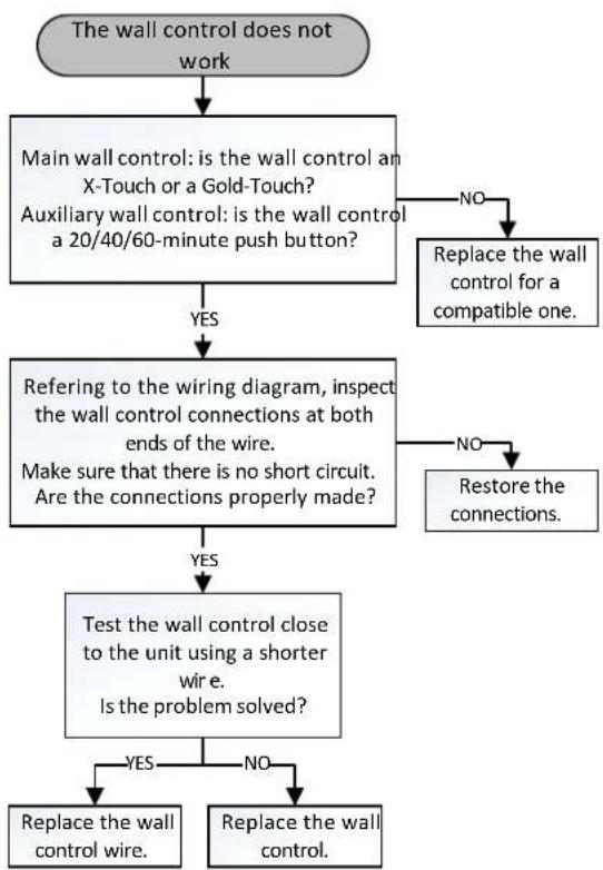
graph TD
    A["The wall control does not work"] --> B["Main wall control: is the wall control an X-Touch or a Gold-Touch? Auxiliary wall control: is the wall control a 20/40/60-minute push button?"]
    B -->|YES| C["Replacing the wall control for a compatible one."]
    B -->|NO| D["Replace the wall control for a compatible one."]
    C --> E["Referring to the wiring diagram, inspect the wall control connections at both ends of the wire. Make sure that there is no short circuit. Are the connections properly made?"]
    D -->|NO| F["Restore the connections."]
    D -->|YES| G["Test the wall control close to the unit using a shorter wire. Is the problem solved?"]
    F --> H["Replace the wall control wire."]
    F --> I["Replace the wall control."]
    G -->|YES| J["Replace the wall control wire."]
    G -->|NO| K["Replace the wall control."]
flowchart
graph TD
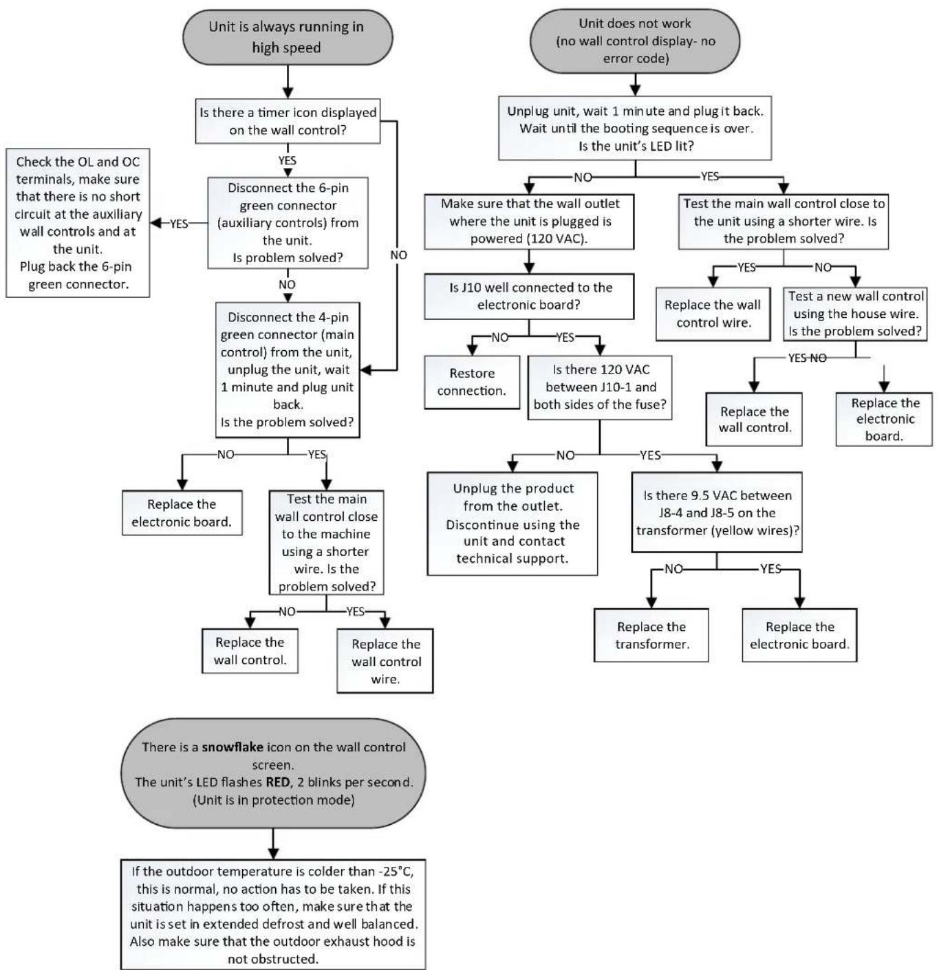
A["Unit is always running in high speed"] --> B["Is there a timer icon displayed on the wall control?"]
B -->|YES| C["Disconnect the 6-pin green connector (auxiliary controls) from the unit. Is problem solved?"]
B -->|NO| D["Check the OL and OC terminals, make sure that there is no short circuit at the auxiliary wall controls and at the unit. Plug back the 6-pin green connector."]
C --> E["Disconnect the 4-pin green connector (main control) from the unit, unplug the unit, wait 1 minute and plug unit back. Is the problem solved?"]
E --> F["Replace the electronic board."]
E --> G["Test the main wall control close to the machine using a shorter wire. Is the problem solved?"]
G --> H["Replace the wall control."]
G --> I["Replace the wall control wire."]
J["Unit does not work (no wall control display- no error code)"] --> K["Unplug unit, wait 1 minute and plug it back. Wait until the booting sequence is over. Is the unit's LED lit?"]
K --> L["Make sure that the wall outlet where the unit is plugged is powered (120 VAC)."]
K --> M["Test the main wall control close to the unit using a shorter wire. Is the problem solved?"]
L --> N["Is J10 well connected to the electronic board?"]
M --> O["Replace the wall control wire."]
M --> P["Test a new wall control using the house wire. Is the problem solved?"]
N --> Q["Restore connection."]
N --> R["Is there 120 VAC between J10-1 and both sides of the fuse?"]
O --> S["Replace the wall control."]
O --> T["Replace the electronic board."]
Q --> U["Unplug the product from the outlet. Discontinue using the unit and contact technical support."]
R --> V["Is there 9.5 VAC between J8-4 and J8-5 on the transformer (yellow wires)?"]
S --> W["Replace the transformer."]
S --> X["Replace the electronic board."]
T --> Y["No"]
T --> Z["Yes"]
U --> AA["Replace the wall control."]
V --> AB["No"]
V --> AC["Yes"]
W --> AD["Replace the electronic board."]
X --> AE["No"]
X --> AF["Yes"]
AG["There is a snowflake icon on the wall control screen.<br>The unit's LED flashes RED, 2 blinks per second.<br>(Unit is in protection mode)"] --> AH["If the outdoor temperature is colder than -25°C, this is normal, no action has to be taken. If this situation happens too often, make sure that the unit is set in extended defrost and well balanced. Also make sure that the outdoor exhaust hood is not obstructed."]
GUIDE D'INSTALLATION ET D'UTILISATION
natural_image
Pure architectural floor plan lines without any text, numbers, or symbolsVE0185
VENMAR AVS
X24 ERV ECM
X24 HRV ECM
X30 ERV ECM
X30 HRV ECM
VENMAR/VÄNEE
X24 ERV ECM-N
X24 HRV ECM-N
X30 ERV ECM-N
X30 HRV ECM-N
VÄNEE GOLD
G2400E ECM
G2400H ECM
G3000E ECM
G3000H ECM
À PROPOS DE CES APPAREILS
Address – Adresse Apt. no. – App. City – Ville Province Postal code – Code postal
Country – Pays E-mail address – Courriel Language preferred – Langue de correspondance
Date of purchase – Date d'achat
flowchart
graph TD
    A["House Icon"] -->|Rotation Arrow| B["CONT"]
    B --> C["Monitor Icon"]
VQ0137
Would you like to receive occasional informational e-mail offers including product updates and special promotions from us? Yes/No
What problem were you trying to solve with your purchase? (Check each one that applies to you.)
| Bad odorsRespiratory problemsExcess of humidityTemperature standardizationLack of fresh air | DustMilewAllergesNo specific problemsOthers | Important to 9 (most important): | |
| PriceWarrantyProduct designVentilation capacityFilter maintenance indicatorFiltration qualityRecirculation | Heal recoveryControlsEase of cleaningManufacturer's reputationEase of useNoise levelOther | ||
| Who installed your unit?Home builderRecommended installer | Friend / familyContractorYourself | ||
Are you connected? Please do not hesitate to complete the product registration card via our Web site at www.bnv.ca
natural_image
Technical line drawing of a mechanical assembly with a magnified inset showing internal components (no text or symbols)Pour l'installateur
5.2.2 À L'AIDE DU SUPPORT MURAL
text_image
Technical diagram showing three stages of a mechanical or electrical assembly with labeled components and directional arrows.5.3 INSTALLATION DES CONDUITS ET DES GRILLES
⚠ AVERTISSEMENT
natural_image
Architectural cross-section diagram of a two-story building with internal fixtures and ventilation ducts (no text or symbols)Pour l'installateur
natural_image
Technical line drawing of a structural frame with circular components and diagonal braces (no text or symbols)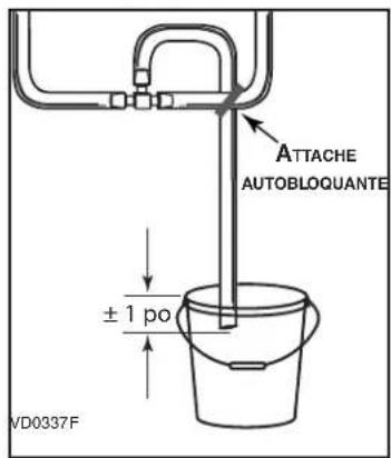
text_image
ATTACHE AUTOBLOQUANTE ± 1 po VD0337F6. COMMANDES MURALES
⚠ AVERTISSEMENT
natural_image
Diagram of a hand connecting three colored wires to a terminal block (no text or symbols)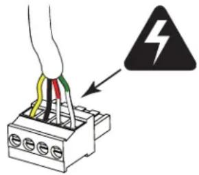
text_image
Diagram showing a cable connector with colored wires and a warning symbol indicating electrical hazard.7. RACCORDEMENT ÉLECTRIQUE À LA FOURNAISE
⚠ AVERTISSEMENT
text_image
Exploded view diagram of a mechanical device with numbered components for identification| N° | DESCRIPTION QTÉ | X24 ERV ECM | X24 HRV ECM | X30 ERV ECM | X30 HRV ECM | X24 ERV ECM-N | X24 HRV ECM-N | X30 ERV ECM-N | X30 HRV ECM-N | G2400E ECM | G2400H ECM | G3000E ECM | G3000H ECM | |
| 1 | ENSEMBLE DE SUPPORTS | 1 | 63419 | 63419 | 63419 | 63419 | 63419 | 63419 | 63419 | 63419 | 63419 | 63419 | 63419 | 63419 |
| 2 | ENS. DE SYSTÈME DE VOLET (INCLUANT 2 VIS DE PLASTIQUE) | 1 63 | 420 634 | 20 634 | 20 6342 | 0 63420 | 63420 634 | 20 63420 6 | 3420 63420 | 63420 63420 | 420 | |||
| 3 | BLOC VENTILATEUR (INCLUANT 3 VIS DE PLASTIQUE) | 2 63 | 421 634 | 21 634 | 21 6342 | 1 63421 | 63421 634 | 21 63421 6 | 3421 63421 | 63421 63421 | 421 | |||
| 4 | FILTRE DE NOYAU VRC (PAIRE) | 1 | 63426 | 63426 | 63426 | 63426 | 63426 | 63426 | ||||||
| FILTRE DE NOYAU VRE (PAIRE) | 1 | 63433 | 63433 | 63433 | ||||||||||
| 5 | NOYAU DE RÉCUP. DE CHALEUR | 1 | 63422 | 63423 | 63422 | 63423 | 63422 | 63423 | ||||||
| NOYAU DE RÉCUP. D'ÉNERGIE | 1 | 63425 | 63425 | 63425 | ||||||||||
| 6 | PORTE ASSEMBLÉE (INCLUANT N° 16) | 1 63 | 429 634 | 29 634 | 29 6342 | 9 63429 | 63429 634 | 29 63429 6 | 3428 63428 | 63428 63428 | 428 | |||
| 7 | PANNEAU DE DROITE | 1 | 63432 | 62495 | 62498 | 62499 | 63432 | 62495 | 62498 | 62499 | 63430 | 62500 | 62502 | 62504 |
| 8 | FILTRE DE NOYAU VRE (PAIRE) | 1 | 63427 | 63427 | 63427 | |||||||||
| 9 | NOYAU DE RÉCUP. D'ÉNERGIE | 1 | 63424 | 63424 | 63424 | |||||||||
| 10 | CARTE FILLE (INCLUANT N° 11) | 1 | 63437 | 63437 | 63437 | 63437 | 63437 | 63437 | 63437 | 63437 | 63437 | 63437 | 63437 | 63437 |
| 11 | BORNIER (POUR COMMANDE PRINCIPALE) | 1 63 | 434 634 | 34 634 | 34 6343 | 4 63434 | 63434 634 | 34 63434 6 | 3434 63434 | 63434 63434 | 434 | |||
| 12 | BORNIER (POUR COMMANDE AUXILIAIRE) | 1 63 | 435 634 | 35 634 | 35 6343 | 5 63435 | 63435 634 | 35 63435 6 | 3435 63435 | 63435 63435 | 435 | |||
| 13 | CARTE ÉLECTRONIQUE (INCLUANT LES N°S 10 ET 12) | 1 | 63436 | 63441 | 63442 | 63443 | SV64392 | SV64393 | SV64394 | SV64395 | 63436 | 63441 | 63442 | 63443 |
| 14 | TRANSFORMATEUR | 1 | 63438 | 63438 | 63438 | 63438 | 63438 | 63438 | 63438 | 63438 | 63438 | 63438 | 63438 | 63438 |
| * | ENSEMBLE THERMISTOR CÔTÉ CHAUD | 1 62 | 481 624 | 481 624 | 481 6248 | 1 62481 | 62481 624 | 81 62481 6 | 2481 62481 | 62481 62481 | 481 | |||
| * | INTER. DE PORTE MAGNÉTIQUE | 1 | 19060 | 19060 | 19060 | 19060 | 19060 | 19060 | 19060 | 19060 | 19060 | 19060 | 19060 | 19060 |
| * | VIS DE PLASTIQUE (JEU DE 6) | 1 | 63439 | 63439 | 63439 | 63439 | 63439 | 63439 | 63439 | 63439 | 63439 | 63439 | 63439 | 63439 |
| * | JEU DE PIÈCES POUR INSTAL. | 1 | 22488 | 22488 | 22488 | 22488 | 22488 | 22488 | 22488 | 22488 | 22488 | 22488 | 22488 | 22488 |