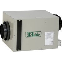
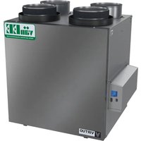
1601510 - Air Conditioning vänEE - Free user manual and instructions
Find the device manual for free 1601510 vänEE in PDF.


| Product Type | Window Air Conditioner |
| Model | 1601510 |
| Brand | vänEE |
| Cooling Capacity | 10,000 BTU/h |
| Power Supply | 115 V ~ 60 Hz, 10 A |
| Dimensions (W x H x D) | 23.6 x 15.4 x 20.5 inches |
| Weight | 65 lbs (29.5 kg) |
| Energy Efficiency Ratio (EER) | 12.0 |
| Refrigerant Type | R-410A |
| Air Flow (CFM) | 350 CFM |
| Noise Level (Indoor/Outdoor) | 52 dB / 65 dB |
| Remote Control | Included (batteries not included) |
| Thermostat Control | Mechanical dial with 7 positions |
| Fan Speeds | 2 (Low, High) + Cool modes |
| Air Direction | Adjustable horizontal louvers |
| Filter Type | Washable mesh filter |
| Filter Cleaning | Every 30 days; vacuum or wash with mild detergent |
| Safety Features | Overload protector, anti-bounce start |
| Spare Parts Availability | Filters, remote, knobs, fan motor available via vänEE website |
| Warranty | 1 year limited (parts and labor) |
Frequently Asked Questions - 1601510 vänEE
User questions about 1601510 vänEE
0 question about this device. Answer the ones you know or ask your own.
Ask a new question about this device
Download the instructions for your Air Conditioning in PDF format for free! Find your manual 1601510 - vänEE and take your electronic device back in hand. On this page are published all the documents necessary for the use of your device. 1601510 by vänEE.
USER MANUAL 1601510 vänEE
AIR EXCHANGERS MODELS
INSTALLATION AND USER MANUAL
READ AND SAVE THESE INSTRUCTIONS
WARNING
- When applicable local regulations comprise more restrictive installation and/or certification requirements, the aforementioned requirements prevail on those of this document and the installer agrees to conform to these at his own expenses.
- This unit must be grounded. The power supply cord has a 3-prong grounding plug for your personal safety. It must be plugged into a mating 3-prong grounding receptacle, grounded in accordance with the national electrical code and local codes and ordinances. Do not remove the ground prong. Do not use an extension cord.
- Risk of electric shocks. All electrical connections must comply with local regulations.
- Installation work and electrical wiring must be done by a qualified person(s) in accordance with all applicable codes and standards, including fire-rated construction codes and standards.
- Before performing any maintenance or servicing, always disconnect the unit from its power source.
- When installing, servicing or cleaning the unit, it is recommended to wear safety glasses and gloves.
- This product employs overload protection (fuse). A blown fuse indicates an overload or short-circuit situation. If the fuse blows, unplug the product and check the polarity and voltage output from the outlet. Replace the fuse as per the servicing instructions (follow marking on power cord tag for proper fuse rating) and check the product. If the replacement fuse blows, a short-circuit may be present and the product should be discarded or returned to an authorized service facility for examination and/or repair.
- Not suitable for use with solid-state speed controls.
- Do not operate any fan with a damaged cord or plug. Discard fan or return to an authorized service facility for examination and/or repair.
- Do not run cord under carpeting. Do not cover cord with throw rugs, runners, or similar coverins. Do not route cord under furniture or appliances. Arrange cord away from traffic area and where it will not be tripped over.
CAUTION
- Do not use your ventilation system when renovating a house or when sanding gypsum. This type of dust may damage the unit.
- The ductwork is intended to be installed in compliance with all applicable codes.
- Do not use your ventilation system when varnishing. Furthermore, if your unit is installed in the attic, we highly insist that you block the stale air intake and fresh air registers. The varnish vapors may damage the unit.
- If your unit is installed in the attic, you should not turn it OFF during the winter time in order to avoid condensation inside the unit and inside the ducts.
TABLE OF CONTENTS
- OPERATIONAL PRINCIPLES....3
- CONTROLS 3-4
- MAINTENANCE 4
- TROUBLESHOOTING....5
- INSTALLATION OF THE SYSTEM....6-12
- WARRANTY 13
1. OPERATIONAL PRINCIPLES
The air exchanger is designed to eliminate problems of excessive humidity, to steady the temperature and the humidity and to filter the air inside your house. The air exchanger carries out the following operations:
AIR CIRCULATION (PRO 200 UNIT ONLY) :
The system circulates the air inside the house, thus steadying the temperature and the humidity throughout.
CIRCULATION WITH AIR EXCHANGE: (ALL UNITS)
While continually circulating the air within the house, the unit also evacuates part of this stale air and replaces it with fresh dry air from the outside.
The following extra benefits are thus obtained: lowering of the humidity, elimination of stale air, cooling of the house on hot summer nights.

FILTRATION:
(ALL UNITS)
When the air flows through the system, a mechanical filter traps dust particles.
2. CONTROLS
2.1 IDENTIFICATION OF PARTS


2.2 How to use the Controls
a) Using the humidity level selector:
Winter: (outside temperature between 5°C and -30°C)
– Position the selector between 50% and 25%, pointing approximately to the corresponding outside temperature.
- If there is condensation or frost on the windows, then lower the humidity level by 1% to 2% every 24 hours until the condensation has evaporated.
- Do not go lower than 25%: The air will become too dry for human comfort.
2. CONTROLS (CONT'D)
2.2 HOW TO USE THE CONTROLS (CONT'D)
a) Using the humidity level selector (cont'd):
Spring and fall:
– Position the selector anywhere between 75% and 50% (higher on warm days, lower on cold days).
- If certain periods during the spring and fall seem more like winter then you should follow the instructions given for humidity control during winter!
Summer:
– Position the selector at 80% during the day.
- If you want to introduce cool fresh air into the house during certain summer nights, then lower the selector to 20% for these nights.
b) Explanations about humidity levels: IMPORTANT
The comfort level for human beings is between 30% and 45% relative humidity. To measure the present humidity level in your house, you can proceed as follows:
– Turn the dial to 80%.
- Turn the dial slowly downwards until you hear a "click". The dial will then be pointing to the value for the present humidity level (precision of 5% ).
Turning the selector lower than the “click” position means that you desire to lower the humidity level in the house. This action will initiate the “air exchange” mode on your ventilation system and means that you are expecting the stale humid air from inside to be replaced with dryer air from outdoors. It is therefore pointless to try and lower the humidity with “air exchange” on rainy or foggy days.
Turning the selector higher than the “click” position means that you are not interested in having your ventilation system function under “air exchange” mode.
Finally keep in mind that the instructions given above are just guidelines. You might prefer different values for the humidity selector, depending on the insulation of your house, the type of windows, or to satisfy the specific needs of certain occupants. After some experimenting, you will eventually develop a control method best adapted to your household needs.
C) Using the circulation selector (Model 11417, for PRO 200 units only)
“Continuous Circulation”: At the exact moment when the desired humidity level is reached, the “air exchange” mode is interrupted and the system continues to operate under “circulation” mode only (see section 1). The “air exchange” mode will be reactivated only if the humidity level in the house goes up higher than the selected value.
“Intermittent Circulation”: At the exact moment when the desired humidity level is reached, the unit goes off. It will automatically start up again in “air exchange” mode if the humidity level in the house goes up higher than the selected value.
Recommendations for a PRO 200 installed in the basement: "Continuous Circulation" during the winter; "Intermittent Circulation" during spring, summer, and fall.
CAUTION
Adjust for "Continuous Circulation" during all 4 seasons if your unit is installed in the attic.
3. MAINTENANCE
Air filter: We recommend that it be cleaned every three months. First, use a vacuum cleaner to remove the accumulated dust. Then wash it in warm soapy water.
Exterior openings: Clean the exterior intake and exhaust screens at least once a year, preferably in autumn.

4. TROUBLESHOOTING
| PROBLEMS | POSSIBLE CAUSES | SOLUTIONS | |
| 1 | Air too dry. | Humidity level incorrectly selected. | Select humidity level according to Section 2. |
| 2 | Persistent condensation. | Humidity level incorrectly selected. | Select humidity level according to Section 2 and give the unit time to respond.Turn on the central heating system.Store the wood outside.Do not completely close curtains, blinds, etc. |
| Too much firewood in the house.Air cannot circulate close to windows.Window frame too cold. | |||
| 3 | Air from distribution register too cold. | Too much air exchange with the exterior. | Install the white ring in the fresh air intake port (section 5.46.1) (Pro 200 model only). |
REPLACEMENT PARTS AND REPAIRS
In order to ensure your ventilation unit remains in good working condition, you must use the manufacturer genuine replacement parts only. The manufacturer replacement parts are specially designed for each unit and are manufactured to comply with all the applicable certification standards and maintain a high standard of safety. Any third party replacement part used may cause serious damage and drastically reduce the performance level of your unit, which will result in premature failing. The manufacturer recommends to contact a certified service depot for all replacement parts and repairs.
5. INSTALLATION OF THE SYSTEM
5.1 INSTALLATION KITS (PRO 100 AND PRO 200 MODELS ONLY)
The table below indicates the installation kits which are needed to correctly install your air exchanger.
Normally, the air exchanger is installed in the basement because it then becomes easier to clean. The model PRO 200, however, can be installed in the attic if a basement installation is impracticable. (Models PRO 100, 41000 and 1601510 should not be installed in the attic.) When you have to install extra registers in the ground floor, use either: two 6" x 10" registers or three 4" x 10" registers.
We strongly recommend that you purchase VENMAR kits and registers.
| YOUR HOUSE | BASEMENTPRO 100 / PRO 200 | ATTICPRO 200 | |
| BUNGALOWBasement stairwell: open, lateral |  | EA 20140 EA 20130 | |
| BUNGALOWBasement stairwell: closed |  | EA 20140+2 OR 3 REGISTERS | EA 20130+2 OR 3 REGISTERS |
| COTTAGEBasement stairwell: closed | 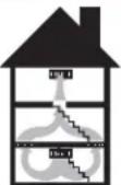 | ||
5.2 LOCATION OF COMPONENTS
Carefully plan the location of all the components before proceeding with the actual installation. The following suggestions will help you find the best location for each components.
Stale air intake register:
- Always locate the register at the highest point in the house, because humidity is concentrated at this point.
- Position the register as far from the stairway as possible and in such a way that the air circulates in all the lived-in spaces in the house.
- Avoid installing the register in a bathroom or a bedroom; place it in a location where the air flows freely (e.g.: living room, kitchen, hallway).
- For silent operation, leave a minimum of 15 feet of flexible duct between the stale air intake register and the unit.
- Do not install the register close to a source of heat. The temperature of the intake air must not exceed 50°C .
Fresh air distribution register:
- Always locate the register in a large, open area in the basement to ensure the greatest possible circulation of air. If, however, your house has no basement or has just an underfloor space, then it will be necessary to locate this register in the ceiling on the first floor and as far as possible from the location of the stale air intake register.
- Position the register as far as possible from the stairway and in such a way that the air circulates in all the lived-in spaces of the house.
- If you have a slow combustion fireplace place the register in such a way that the heat from this fireplace can be distributed throughout the house.
- For silent operation, leave at least 15 feet of flexible duct between the fresh air distribution register and the unit.
5. INSTALLATION OF THE SYSTEM (CONT'D)
5.2 LOCATION OF COMPONENTS (CONT'D)
Extra registers:
- If your basement stairwell is often closed, then you must install 2 or 3 extra registers (not supplied with the kits) in the floor at the ground floor level. As an alternative, you could install one of these registers above the stairwell door or on a wall adjacent to the stairwell. Locate these registers so that the air will be able to circulate freely (living room, hallway, etc.). Avoid placing them near the state air intake register.
Unit:
- Model PRO 200 can be installed in either the basement or the attic. Models PRO 100, 41000 and 1601510 can be installed in the basement only.
- Place the unit as close as possible to an outside wall to minimize the length of the insulated flexible ducts. Place the unit in such a way as to respect the lengths of the ducts supplied in the parts kits (if need be). Place the unit far from the areas of the house where peace and quiet are desired.
- If possible, place the unit close to an electrical outlet. Make sure you have the required wires for the electrical installation: AWG 14/2 wire necessary for all models plus an extra AWG 14/3 wire for model PRO 200.
- Position the unit so as to permit easy access to the filter. Model PRO 200 can be installed upside down, which in certain cases makes it easier to get at the filter (see illustration at right).

PRO 200 in reversed position
Flexible ducts:
- Use closets, cupboards and other storage spaces to run duct from one floor to another (do not use wall cavities). Stretch duct and install in straight lines as much as possible. Do not alter the length of duct supplied with the different kits (if need be). The efficiency of your ventilation system might be reduced.
Control:
- Locate the control on the ground floor of the house in an area where air circulates (e.g.: hallway, living room, dining room, etc.). Never place it near a doorway to the outside, nor on an exterior wall. Place the control approximately 1.5 meters (60 inches) from the floor.
Exterior openings:
- Position the fresh air intake port far from sources of contamination such as the garage, dryer outlet, central vacuum system, gas regulator.
Place the openings at least 45 cm (18 inches) above the ground.
Leave at least 1.8 meters (6 feet) between the two openings.
The prevailing winds should not blow the stale air towards the fresh air intake port.

5. INSTALLATION OF THE SYSTEM (CONT'D)
5.3 SUGGESTED TOOLS

Robertson or a Phillips screwdriver no. 1

Robertson or a Phillips screwdriver no. 2

Flat tip screwdriver

Cutting pliers

Electric drill
VQ0014

Jig saw or hand or electric compass saw

Caulking gun and tube of silicone sealant

Adhesive duct tape roll

Metal shears (if the exterior covering of your house is aluminum or plastic)

Chisel and hammer (if th exterior covering of your house is brick)
VQ0015
5.4 INSTRUCTIONS FOR THE INSTALLATION
Once you have decided on the best location for all the components and for all the various openings that will have to be cut out, and the necessary tools have been procured, then you are ready to commence the actual installation of your system. To facilitate the installation we strongly recommend that you follow the detailed steps below:
1 You will find, on pages 11 and 12, two large drawings which illustrate the different types of installation. Determine which one corresponds to your particular situation and encircle the drawing for easy future reference.
You should follow the procedure below to "connect" an insulated flexible duct to its corresponding opening:
a) Connect the interior flexible duct to the hole using screws and/or a duct tie.
b) Carefully seal the connection with duct tape.
c) Pull the insulation over the joint.
d) Once more apply duct tape to the joint making an airtight seal. Avoid pulling the tape too tight around the duct, as this will compress the insulation making it loose its efficiency.

2 Cut out all the round holes that will permit the flexible duct to pass through walls, floors and ceilings, as well as the holes where you intend to install all round registers (diffusers). A 6" duct requires a 6½" hole and an 8" duct requires an 8¼" hole.
Installation of round registers (included in your kit, if need be):
a) Connect the duct to the plastic support provided (6" ring-pipe assembly).
b) Screw the plastic support into the ceiling.
c) Screw the register onto the plastic support.
5. INSTALLATION OF THE SYSTEM (CONT'D)
5.4 INSTRUCTIONS FOR THE INSTALLATION (CONT'D)
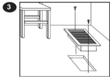
3 Cut out all the rectangular holes in the locations where you intend to install rectangular registers. All 6" x 10" registers require 6" x 9¾" holes and all 4" x 10" registers require 4" x 9¾" holes.
Install the rectangular registers in the correct locations and attach the corresponding flexible duct to these registers. (Attention, if you have “extra registers”, they are not connected to any ducts! See illustration at right.)
4 Cut out the two exterior openings. These holes should measure 4 1/4 " diameter. Basement openings are cut in the end-joists, whereas attic openings are cut in the soffit.
Install the exterior ports and attach the corresponding flexible duct: If in the basement, connect the insulated duct to the intake port and, if in the attic, connect the insulated duct to the exhaust port. Use silicone sealer to waterproof the openings if installed in the basement.
5 Installation of the unit. Attach the 4 hooks to the 4 corners of the unit. Using 4 screws attach the 4 chains to the ceiling joists. Put the springs on the chains. The springs stop the vibrations from the unit being transmitted to the structure of your house. Suspend the unit using the chains and hooks.

6.1 On PRO 200 unit only, install the white ring. Install it in the unit's fresh air from outside port. This ring controls the flow of fresh air. Remove the ring only if you make frequent use of a wood-burning stove.
CAUTION
Make sure the unit is level.

VO0016
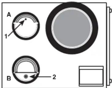
6.2 On PRO 100, 41000 and 1601510 units only, check the stale air to outside (A) and fresh air from outside (B) ports. Those both ports are equipped with special dampers; according to the unit installation position (normal or reversed), set these dampers as follows:
Stale air to outside port damper: The small hole (1) must always be on the upper side of the damper.
Fresh air from outside port damper: The weight (2) must always be on the lower side of the damper.
NOTE: To set the port damper position, simply rotate the port until the right position as been reached.
VJ0044
Unit on normal position

Unit on reversed position
5. INSTALLATION OF THE SYSTEM (CONT'D)
5.4 INSTRUCTIONS FOR THE INSTALLATION (CONT'D)
7 Connect all the flexible ducts to the unit as shown in the drawing which you have previously encircled. (If your unit is installed upside down, correct the drawing accordingly.) Respect the duct lengths supplied with the different kits (if need be). Stretch the ducts and keep them as straight as possible. (Exceptionally, you can shorten the ducts but do not try to add extra length to them.)
8 Electrical Installation.
Make hole in the wall at the chosen location for the control.
Run the AWG 14/2 and, if need be, the AWG 14/3 wire in the walls.
Connect the wires according to the drawings below.
Screw the control onto the wall.


9 rify the operation of your unit:
Connect the unit to a power source. By adjusting the control as described in Sections 2.2b and 2.2c, verify that the unit works properly. If the unit does not work properly, refer to the rules to follow on the warranty document of the unit.
5. INSTALLATION OF THE SYSTEM (CONT'D)
BASEMENT KIT EA 20140

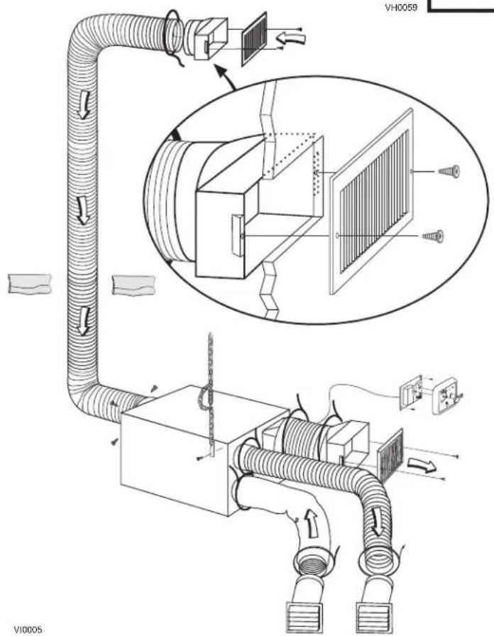
5. INSTALLATION OF THE SYSTEM (CONT'D)
ATTIC
KIT EA 20130


6. WARRANTY
This unit is a high quality product, built and packaged with care. The manufacturer warrants to the original purchaser of its products, that such products will be free from defects for the period stated below, from date of original purchase. For this unit, the warranty covers parts only against any operational defect. This is a 2-year warranty. Subject to perform the core maintenance according to user guide recommendations, the heat recovery core (HRV) has a limited lifetime warranty. If any defect should occur, we urge you to read the user guide carefully. If the problem persists, observe the following rules:
RULES TO FOLLOW
If the unit is defective, contact your ventilation contractor (see address on your user manual cover page). The contractor will determine with you the reason for the defect, and if needed, do the replacement or repair.
If ever it is impossible to reach your ventilation contractor, call 1-800-567-3855 (in North America);
the personnel will be pleased to give you the phone number of a distributor or a service center near you.
REPLACEMENT PARTS AND REPAIR
In order to ensure your ventilation unit remains in good working condition, you must use the manufacturer's genuine replacement parts only. The manufacturer's genuine replacement parts are specially designed for each unit and are manufactured to comply with all the applicable certification standards and maintain a high standard of safety. Any third party replacement part used may cause serious damage and drastically reduce the performance level of your unit, which will result in premature failing. The manufacturer also recommends to contact a service depot certified by the manufacturer for all replacement parts and repair.
BILL OF PURCHASE
No replacement or repair covered by the warranty will be carried out unless the unit is accompanied by a copy of the original bill of purchase. Please retain your original.
MISCELLANEOUS COSTS
In each case, the labor costs for the removal of a defective part and/or installation of a compliant part will not be covered by the manufacturer.
CONDITIONS AND LIMITATIONS
These units are created for residential use only and must be used in a building as defined below:
Building: All structures zoned and/or erected for the act, process or art of human or animal habitation and/or the storage or warehousing of goods. Residential use: Dwelling, lodging, suite: Building, or part of a building, intended to act as either the domicile to one or several people which can include general sanitary, food consumption and rest facilities. Buildings of only one room or a group of rooms including those occupied by a tenant or owner; comprise the lodgings, the individual rooms of the motels, hotels, rooming/lodging houses, boarding/half-way/foster homes, dormitories, and suites, as well as the stores and the business establishments constituted by only one room in a dwelling.
Commercial use: Agricultural establishment, commercial establishment for assembly, care, or detention: Building or part of a building that does not contain a dwelling, situated on land dedicated to agriculture or farming and used primarily to shelter animals, or for the production, the storage or the treatment of agricultural or horticultural products or animal food. Building or part of a building, used for the display or retail of goods, professional or personal services, or commodities. Building, or part of a building used by persons gathering for civic activities, religious or political assembly, tourism, educational/vocational training, recreation or the consumption of food or drink. Building, or part of a building used to shelter persons of impaired physical or psychological states, persons requiring palliative care or medical treatments, or persons for reasons out of their control, cannot escape harm or threat of danger autonomously.
Industrial use: Building, or part of a building, used for the assembly, the manufacture, the creation, the treatment, the repair or the storage of products and combustible materials and that contain fuels that when ignited or exploded in sufficient quantity may constitute a risk of fire.
The above warranty applies to all cases where the damage is not a result of poor installation, improper use, mistreatment or negligence, acts of God, or any other circumstances beyond the control of the manufacturer.
Furthermore, the manufacturer will not be held responsible for any bodily injury or damage to personal property or real estate, whether caused directly or indirectly by the unit. This warranty supersedes all prior warranties.
PRODUCT REGISTRATION CARD - FICHE D'ENREGISTREMENT DU PRODUIT
Country – Pays E-mail address – Courriel Language preferred – Langue de correspondance
Date of purchase – Date d'achat
Would you like to receive occasional informational e-mail offers including product updates and special promotions from us? Yes/No
What problem were you trying to solve with your purchase? (Check each one that applies to you.)
| ☐ Bad odors ☐ Respiratory problems ☐ Excess of humidity ☐ Temperature standardization ☐ Lack of fresh air | ☐ Dust ☐ Mildew ☐ Allergies ☐ No specific problems ☐ Others | Important to 3 (most important). | |
| — Price — Warranty — Product design — Ventilation capacity — Filter maintenance indicator — Filtration quality — Recirculation | — Heat recovery — Controls — Ease of cleaning — Manufacturer's reputation — Ease of use — Noise level — Other | ||
| Who installed your unit? | |||
| ☐ Home builder ☐ Recommended installer | ☐ Friend / Family ☐ Contractor ☐ Yourself | ||
Are you connected? Please do not hesitate to complete the product registration card via our Web site at www.bnv.ca

- AIR EXCHANGERS MODELS
- INSTALLATION AND USER MANUAL
- WARNING
- CAUTION
- TABLE OF CONTENTS
- OPERATIONAL PRINCIPLES
- FILTRATION
- CONTROLS
- 2.1 IDENTIFICATION OF PARTS
- 2.2 HOW TO USE THE CONTROLS
- CONTROLS (CONT'D)
- 2.2 HOW TO USE THE CONTROLS (CONT'D)
- SPRING AND FALL
- SUMMER
- EXPLANATIONS ABOUT HUMIDITY LEVELS: IMPORTANT
- MAINTENANCE
- TROUBLESHOOTING
- REPLACEMENT PARTS AND REPAIRS
- INSTALLATION OF THE SYSTEM
- 5.1 INSTALLATION KITS (PRO 100 AND PRO 200 MODELS ONLY)
- 5.2 LOCATION OF COMPONENTS
- STALE AIR INTAKE REGISTER
- FRESH AIR DISTRIBUTION REGISTER
- INSTALLATION OF THE SYSTEM (CONT'D)
- 5.2 LOCATION OF COMPONENTS (CONT'D)
- EXTRA REGISTERS
- UNIT
- FLEXIBLE DUCTS
- CONTROL
- EXTERIOR OPENINGS
- 5.3 SUGGESTED TOOLS
- 5.4 INSTRUCTIONS FOR THE INSTALLATION
- 5.4 INSTRUCTIONS FOR THE INSTALLATION (CONT'D)
- 8 ELECTRICAL INSTALLATION
- 9 RIFY THE OPERATION OF YOUR UNIT
- WARRANTY
- RULES TO FOLLOW
- REPLACEMENT PARTS AND REPAIR
- BILL OF PURCHASE
- MISCELLANEOUS COSTS
- CONDITIONS AND LIMITATIONS
- PRODUCT REGISTRATION CARD - FICHE D'ENREGISTREMENT DU PRODUIT
Brand : vänEE
Model : 1601510
Category : Air Conditioning