
D28154 - Grinder DEWALT - Free user manual and instructions
Find the device manual for free D28154 DEWALT in PDF.

| Brand | DeWALT |
| Model | D28154 |
| Product type | Angle grinder (grinder) |
| Voltage | 230 V |
| Power consumption | 1200 W |
| No-load speed | 10 000 min⁻¹ |
| Max. wheel/disc diameter | 125 mm |
| Shaft width | M14 |
| Weight | 1.8 kg |
| Recommended fuse | 10 A (for 230 V) |
| Sound pressure level (LpA) | 89.9 dB(A) |
| Sound power level (LWA) | 97.9 dB(A) |
| Vibration (weighted acceleration) | < 2.5 m/s² |
| Double insulation | Yes (class II, no earth connection needed) |
| Soft start | Yes (on models D28152/D28153/D28155/D28156/D28157) |
| Main functions | Grinding, cutting (steel, masonry), brushing, sanding (with optional accessories) |
| Safety protections | Adjustable guard, spindle lock button, removable side handle, on/off switch with continuous lock |
| Maintenance and cleaning | No additional lubrication required; regularly clean ventilation slots with a soft cloth |
| Spare parts and repairability | Repairs by an authorized DEWALT agent only; use original spare parts |
| Warranty | 30 days satisfaction, 1 year free maintenance, 1 year manufacturer's warranty (subject to conditions) |
Frequently Asked Questions - D28154 DEWALT
User questions about D28154 DEWALT
0 question about this device. Answer the ones you know or ask your own.
Ask a new question about this device
Download the instructions for your Grinder in PDF format for free! Find your manual D28154 - DEWALT and take your electronic device back in hand. On this page are published all the documents necessary for the use of your device. D28154 by DEWALT.
USER MANUAL D28154 DEWALT
A
B
C1
C2
D
E
VINKELSLIBER D28127/D28128/D28129/D28151(K)/D28152/D28153/D28154(K)/D28155(K)/D28156/D28157/D28187
Tillykke!
You have chosen a DEWALT tool. Years of experience, thorough product development and innovation make DEWALT one of the most reliable partners for professional power tool users.
Technical data
| D28127 D28128 D28129 D28151 D28152 D28153 | |
| Voltage V 230 230 230 230 230 230 | |
| (U.K. & Ireland only) V 230/115 | |
| Power input W 800 900 850 900 1,000 1,100 | |
| No-load speed min | -1 10,000 10,000 10,000 10,000 10,000 10,000 |
| Wheel diameter mm 115 115 115 125 125 125 | |
| Spindle diameter M14 M14 M14 M14 M14 M14 | |
| Weight kg 1.7 1.7 1.7 1.7 1.7 1.7 | |
| D28154 D28155 D28156 D28157 D28187 | |
| Voltage V 230 230 230 230 230 | |
| (U.K. & Ireland only) V 230/115 | |
| Power input W 1,200 1,400 1,400 1,250 1,200 | |
| No-load speed min | -1 10,000 10,000 2,800-10,000 10,000 9,300 |
| Wheel diameter mm 125 125 125 125 150 | |
| Spindle diameter M14 M14 M14 M14 M14 | |
| Weight kg 1.8 1.8 1.8 1.7 2.0 | |
Fuses:
| Europe 230 V tools | 10 Amperes, mains | |
| U.K. & Ireland | 230 V tools | 13 Amperes, in plugs |
The following symbols are used throughout this manual:

Denotes risk of personal injury, loss of life or damage to the tool in case of non-observance of the instructions in this manual.

Denotes risk of electric shock.

Fire hazard.
EC-Declaration of conformity

D28127/D28128/D28129/D28151(K)/D28152/D28153/D28154(K)/D28155(K)/D28156/D28157/D28187
DEWALT declares that these power tools have been designed in compliance with: 98/37/EEC, 89/336/EEC, 73/23/EEC, EN 50144, EN 55014-2, EN 55014-1, EN 61000-3-2 & EN 61000-3-3.
For more information, please contact DeWALT at the address below, or refer to the back of the manual.
Level of sound pressure according to 86/188/EEC & 98/37/EEC, measured according to EN 50144:
L_pA (sound pressure) dB(A)* 89.9
L_WA (acoustic power) dB(A) 97.9
* at the operator's ear

Take appropriate measures for the protection of hearing.
Weighted root mean square acceleration value according to EN 50144:
< 2.5 m/s²
Director Engineering and Product Development Horst Großmann

When using power tools, always observe the safety regulations applicable in your country to reduce the risk of fire, electric shock and personal injury.
Read all of this manual carefully before operating the tool.
Save this manual for future reference.
General
1 Keep work area clean
Cluttered areas and benches can cause accidents.
2 Consider work area environment
Do not expose the tool to rain. Do not use the tool in damp or wet conditions. Keep the work area well lit (250 - 300 Lux). Do not use the tool where there is a risk of causing fire or explosion, e.g. in the presence of flammable liquids and gases.
3 Keep children away
Do not allow children, visitors or animals to come near the work area or to touch the tool or the mains cable.
4 Dress properly
Do not wear loose clothing or jewellery, as these can be caught in moving parts. Wear protective hair covering to keep long hair out of the way. When working outdoors, preferably wear suitable gloves and non-slip footwear.
5 Personal protection
Always use safety glasses. Use a face or dust mask whenever the operations may produce dust or flying particles. If these particles might be considerably hot, also wear a heat-resistant apron. Wear ear protection at all times.
6 Guard against electric shock
Prevent body contact with earthed surfaces (e.g. pipes, radiators, cookers and refrigerators). When using the tool under extreme conditions (e.g. high humidity, when metal swarf is being produced, etc.), electric safety can be improved by inserting an isolating transformer or a (FI) earth-leakage circuit-breaker.
7 Do not overreach
Keep proper footing and balance at all times.
8 Stay alert
Watch what you are doing. Use common sense. Do not operate the tool when you are tired.
9 Secure workpiece
Use clamps or a vice to hold the workpiece. It is safer and it frees both hands to operate the tool.
10 Connect dust extraction equipment
If devices are provided for the connection of dust extraction and collection facilities, ensure that these are connected and properly used.
11 Remove adjusting keys and wrenches
Always check that adjusting keys and wrenches are removed from the tool before operating the tool.
12 Extension cables
Before use, inspect the extension cable and replace if damaged. When using the tool outdoors, only use extension cables intended for outdoor use and marked accordingly.
13 Use appropriate tool
The intended use is described in this instruction manual. Do not force small tools or attachments to do the job of a heavy-duty tool. The tool will do the job better and safer at the rate for which it was intended. Do not force the tool.
Warning! The use of any accessory or attachment or performance of any operation with this tool other than those recommended in this instruction manual may present a risk of personal injury.
14 Check for damaged parts
Before use, carefully check the tool and mains cable for damage. Check for misalignment and seizure of moving parts, breakage of parts, damage to guards and switches and any other conditions that may affect its operation. Ensure that the tool will operate properly and perform its intended function. Do not use the tool if any part is damaged or defective. Do not use the tool if the switch does not turn it on and off. Have any damaged or defective parts replaced by an authorised DEWALT repair agent. Never attempt any repairs yourself.
15 Unplug tool
Switch off and wait for the tool to come to a complete standstill before leaving it unattended. Unplug the tool when not in use, before changing any parts of the tools, accessories or attachments and before servicing.
16 Avoid unintentional starting
Do not carry the tool with a finger on the switch. Be sure that the tool is switched off before plugging in.
17 Do not abuse cord
Never carry the tool by its cord. Never pull the cord to disconnect from the socket. Keep the cord away from heat, oil and sharp edges.
18 Store idle tools
When not in use, tools must be stored in a dry place and locked up securely, out of reach of children.
19 Maintain tools with care
Keep the tools in good condition and clean for better and safer performance. Follow the instructions for maintenance and changing accessories. Keep all handles and switches dry, clean and free from oil and grease.
20 Repairs
This tool is in accordance with the relevant safety regulations. Have your tool repaired by an authorised DEWALT repair agent. Repairs should only be carried out by qualified persons using original spare parts; otherwise this may result in considerable danger to the user.
Additional safety rules for grinders
- Your grinder has been designed for grinding and cutting masonry and steel.

Do not cut or grind light metal with a magnesium content exceeding 80% since this type of metal is flammable.
- Do not use any accessories other than fibre reinforced grinding and cutting discs.
- Use the grinding and cutting discs recommended by the manufacturer only.
- The max. allowable speed of the grinding wheel or cutting disc must always be equal to or greater than the no-load speed of the tool specified on the nameplate.
- Do not cut workpieces requiring a maximum depth of cut exceeding that of the cutting disc.
- Do not use grinding and cutting discs that do not conform to the dimensions stated in the technical data. Do not use any spacers to make a disc fit onto the spindle.
- Inspect grinding and cutting discs before each use. Do not use chipped, cracked or otherwise defective discs.
- If provided, ensure that blotters are used when the disc is fitted onto the spindle.
- When applying a threaded hole disc, ensure that the thread is long enough to accept the spindle.
- Ensure that the grinding or cutting disc is mounted correctly before use.
- Let the tool run at no-load in a safe position for at least 30 seconds. If there is a considerable vibration or if any other defect occurs, stop the tool and check it to determine the cause.
- Do not operate this tool without the guard in place.
- Check that the workpiece is properly supported.
- Do not operate the tool near flammable liquids, gases or dust. Sparks or hot chips from cutting or arcing motor brushes may ignite combustible materials.
- Do not operate the tool while standing in line with the disc. Keep other persons away from the work area.
- Do not use cutting discs for side grinding.
- Do not operate the spindle lock while the tool is running.
- Beware that after switching off the tool the wheel continues to rotate for a short period.
- Always store grinding and cutting discs in a dry place.
Labels on tool
The following pictographs are shown on the tool:

Read the instruction manual before use

Wear safety glasses

Wear ear protection
Package contents
The package contains:
1 Angle grinder
1 Guard
1 Side handle
1 Flange set
1 Two-pin spanner
1 Instruction manual
1 Exploded drawing
- Check for damage to the tool, parts or accessories which may have occurred during transport.
- Take the time to thoroughly read and understand this manual prior to operation.
Description (fig. A)
Your angle grinder has been designed for professional grinding and cutting applications.
1 On/off switch
2 Speed control dial (D28156)
3 Spindle lock
4 Guard
5 Side handle
D28152/D28153/D28155/D28156/D28157 -
Soft start feature
The soft start feature allows a slow speed build-up to avoid an initial jerk when starting. This feature is particularly useful when working in confined spaces.
Electrical safety
The electric motor has been designed for one voltage only. Always check that the power supply corresponds to the voltage on the rating plate.

Your DEWALT tool is double insulated in accordance with EN 50144; therefore no earth wire is required.
Mains plug replacement (U.K. & Ireland only)
- Should your mains plug need replacing and you are competent to do this, proceed as instructed below. If you are in doubt, contact an authorized DeWALT repair agent or a qualified electrician.
- Disconnect the plug from the supply.
- Cut off the plug and dispose of it safely; a plug with bared copper conductors is dangerous if engaged in a live socket outlet.
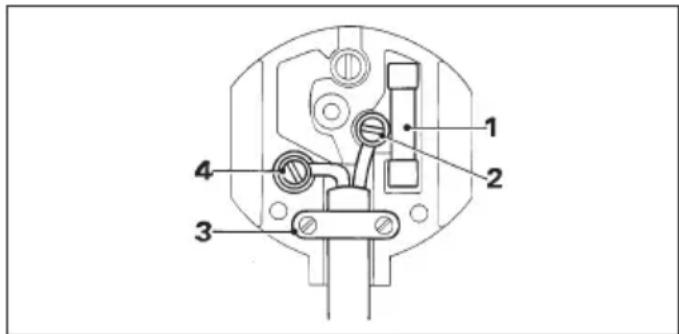
- Only fit 13 Amperes BS1363A approved plugs fitted with the correctly rated fuse (1).
- The cable wire colours, or a letter, will be marked at the connection points of most good quality plugs. Attach the wires to their respective points in the plug (see below). Brown is for Live (L) (2) and Blue is for Neutral (N) (4).
- Before replacing the top cover of the mains plug ensure that the cable restraint (3) is holding the outer sheath of the cable firmly and that the two leads are correctly fixed at the terminal screws.

Never use a light socket.
Never connect the live (L) or neutral (N) wires to the earth pin marked E or 12
For 115 V units with a power rating exceeding 1500 W, we recommend to fit a plug to BS4343 standard.
Using an extension cable
If an extension cable is required, use an approved extension cable suitable for the power input of this tool (see technical data). The minimum conductor size is 1.5 mm^2 .
When using a cable reel, always unwind the cable completely.
Also refer to the table below.
Conductor size (mm ^2 ) Cable rating (Amperes)
| 0.75 6 |
| 1.00 10 |
| 1.50 15 |
| 2.50 20 |
| 4.00 25 |
| Cable length (m) | |||||||||
| 7.5 15 25 30 45 60 | |||||||||
| Voltage Amperes Cable rating (Amperes) | |||||||||
| 1 | 1 | 5 | 0 | - | 2 | . | 0 | 6 | 6 |
| 2.1 | - | 3.4 | 6 | 6 | 6 | 6 | 15 | ||
| 3.5 | - | 5.0 | 6 | 6 | 10 | 15 | 20 | ||
| 5.1 | - | 7.0 | 10 | 10 | 15 | 20 | 25 | ||
| 7.1 | - | 12.0 | 15 | 15 | 20 | 25 | 25 | ||
| 12.1 | - | 20.0 | 20 | 20 | 25 | - | - | ||
| 230 | 0 | - | 2.0 | 6 | 6 | 6 | 6 | 6 | |
| 2.1 | - | 3.4 | 6 | 6 | 6 | 6 | 6 | ||
| 3.5 | - | 5.0 | 6 | 6 | 6 | 6 | 10 | ||
| 5.1 | - | 7.0 | 10 | 10 | 10 | 15 | 15 | ||
| 7.1 | - | 12.0 | 15 | 15 | 15 | 15 | 20 | ||
| 12.1 | - | 20.0 | 20 | 20 | 20 | 20 | 25 | ||
Assembly and adjustment

Prior to assembly and adjustment always unplug the tool.
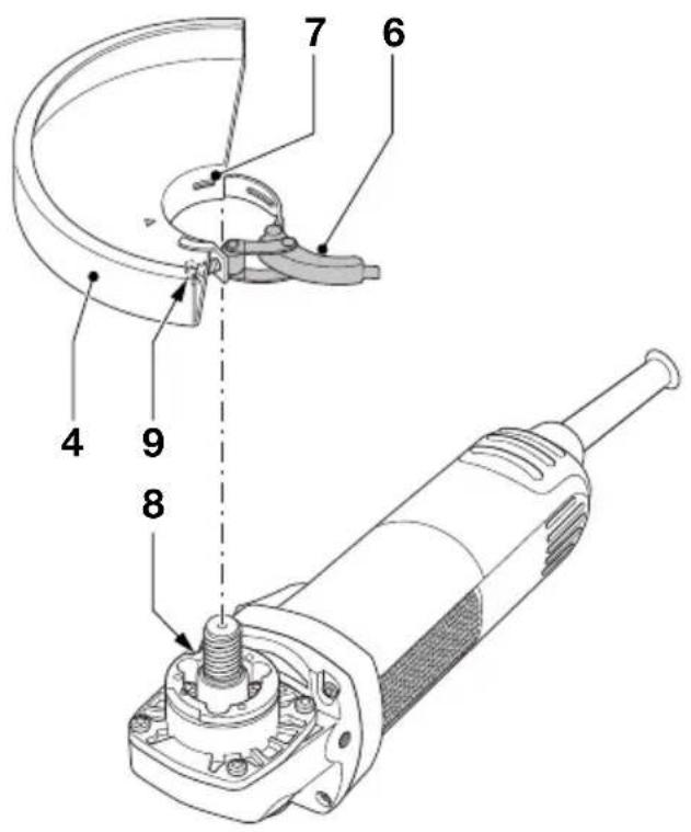
Mounting and removing the guard (fig. B)
- Place the angle grinder on a table, spindle up.
- Release the clamping lock (6) and hold the guard (4) over the tool as shown.
- Align the lugs (7) with the notches (8).
- Press the guard down and rotate it to the required position.
- If required, increase the clamping force by tightening the screw (9).
- Tighten the clamping lock.
- To remove the guard, release the clamping lock.

Never use the tool without the guard in place.
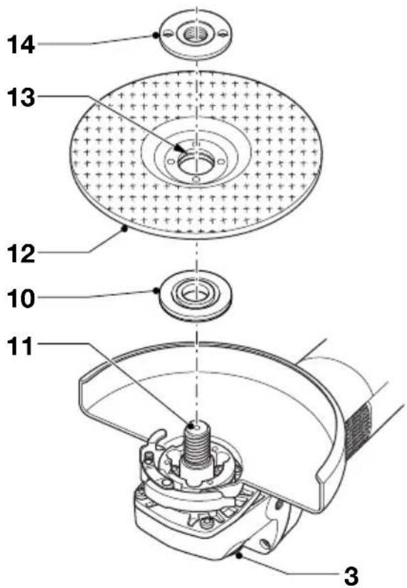
Fitting and removing a grinding or cutting disc (fig. C1 & C2)
- Place the tool on a table, guard up.
- Fit the inner flange (10) correctly onto the spindle (11) (fig. C1).
- Place the disc (12) on the flange (10). When fitting a disc with a raised center, make sure that the raised centre (13) is facing the flange (10).
-
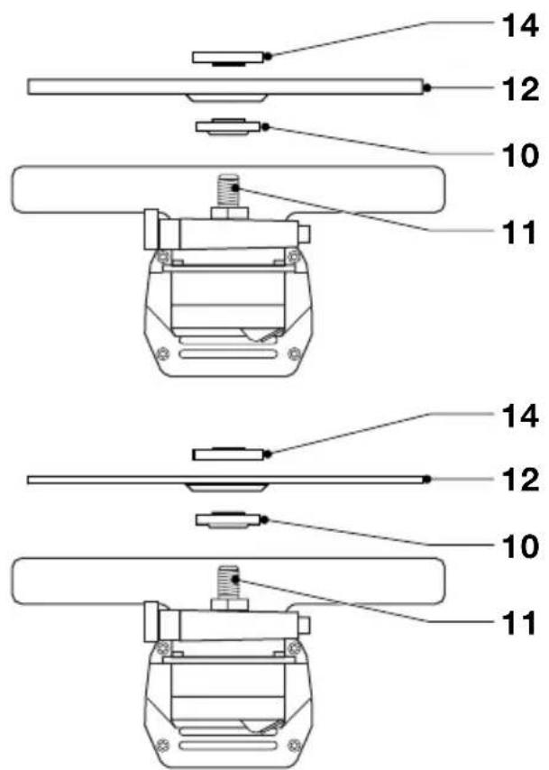
Screw the outer flange (14) onto the spindle (11) (fig. C2):
-
the ring on the flange (14) must face towards the disc when fitting a grinding disc (A);
- the ring on the flange (14) must face away from the disc when fitting a cutting disc (B).
- Press the spindle lock (3) and rotate the spindle 6 (161) until it locks in position.
- Tighten the flange (14) with the two-pin spanner supplied.
- Release the spindle lock.
- To remove the disc, loosen the flange (14) with the two-pin spanner.

Do not use a damaged disc.
Fitting a wire cup brush
- Screw the wire cup brush directly onto the spindle without using the spacer and threaded flange.
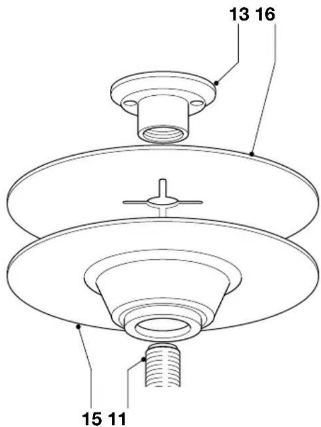
Mounting and removing the rubber backing pad (fig. D)
The rubber backing pad is available as an option.
- Remove the guard from the tool.
- Press the backing pad (15) onto the spindle (11). The inner flange is not needed.
- Position the abrasive disc (16) on the pad.
- Screw the outer flange (14) onto the spindle (11).
- Press the spindle lock and rotate the pad (15) until it locks in position.
- Tighten the flange (14) using the two-pin spanner supplied.
- Release the spindle lock.
- To remove the pad, loosen the flange (14) with the two-pin spanner.
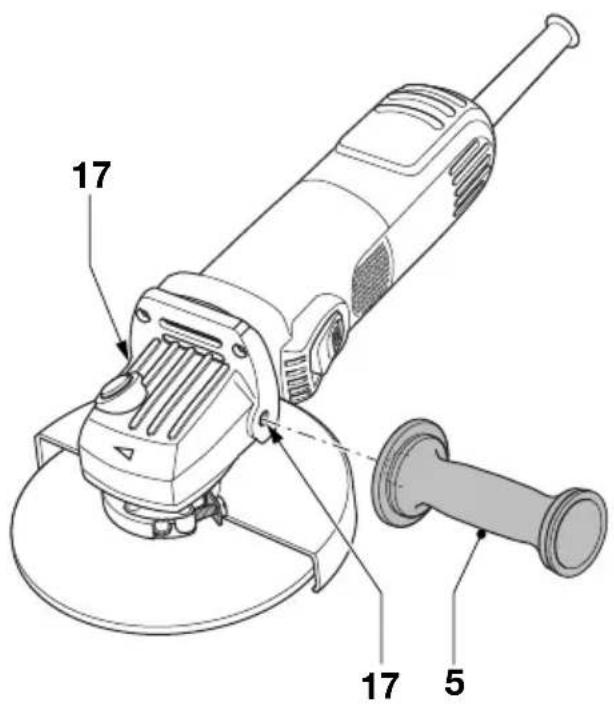
Mounting the side handle (fig. E)
- Screw the side handle (5) tightly into one of the holes (17) on either side of the gear case.
Instructions for use

• Always observe the safety instructions and applicable regulations.
- Ensure all materials to be ground or cut are secured in place.
- Apply only a gentle pressure to the tool. Do not exert side pressure on the disc.
- Avoid overloading. Should the tool become hot, let it run a few minutes under no load condition.
Prior to operation:
- Install the guard and appropriate disc or wheel. Do not use excessively worn discs or wheels.
- Be sure the inner and outer flange are mounted correctly.
- Make sure the disc or wheel rotates in the direction of the arrows on the accessory and the tool.
Switching on and off (fig. A)
- To run the tool, press the on/off switch (1).
- For continuous operation, press the switch completely forward.
- To stop the tool, release the switch. To stop the tool in continuous operation, press on the back part of the switch.

Do not switch the tool on or off when under load.
Consult your dealer for further information on the appropriate accessories.
Maintenance
Your DEWALT Power Tool has been designed to operate over a long period of time with a minimum of maintenance. Continuous satisfactory operation depends upon proper tool care and regular cleaning.

Lubrication
Your power tool requires no additional lubrication.

Cleaning
Keep the ventilation slots clear and regularly clean the housing with a soft cloth.

Unwanted tools and the environment
Take your tool to an authorized DeWALT repair agent where it will be disposed of in an environmentally safe way.
GUARANTEE
• 30 DAY NO RISK SATISFACTION GUARANTEE •
If you are not completely satisfied with the performance of your DEWALT tool, simply return it within 30 days, complete as purchased, to the point of purchase, for a full refund or exchange. Proof of purchase must be produced.
• ONE YEAR FREE SERVICE CONTRACT •
If you need maintenance or service for your DeWALT tool, in the 12 months following purchase, it will be undertaken free of charge at an authorized DeWALT repair agent. Proof of purchase must be produced. Includes labour and spare parts for Power Tools. Excludes accessories.
• ONE YEAR FULL WARRANTY •
If your DEWALT product becomes defective due to faulty materials or workmanship within 12 months from the date of purchase, we guarantee to replace all defective parts free of charge or, at our discretion, replace the unit free of charge provided that:
• The product has not been misused.
• Repairs have not been attempted by unauthorized persons.
- Proof of purchase date is produced.
This guarantee is offered as an extra benefit and is additional to consumers statutory rights.
For the location of your nearest authorized DEWALT repair agent, please use the appropriate telephone number on the back of this manual. Alternatively, a list of authorized DEWALT repair agents and full details on our after-sales service are available on the Internet at
www.2helpU.com.
AMOLADORA ANGULAR D28127/D28128/ D28129/D28151(K)/D28152/D28153/ D28154(K)/D28155(K)/D28156/D28157/D28187
¡Enhorabuena!
Director Engineering and Product Development Horst Großmann

L'emballage contient:
1 Meuleuse d'angle
1 Carter de protection
1 Poignée latérale
1 Jeu de flasques
1 Clé à ergots
(Isolation double) - outils
Director Engineering and Product Development Horst Großmann

DEWALT, Richard-Klinger-Straße 40, D-65510, Idstein, Duitsland
Director Engineering and Product Development Horst Großmann

DEWALT, Richard-Klinger-Straße 40, D-65510, Idstein, Tyskland
Director Engineering and Product Development Horst Großmann

DEWALT, Richard-Klinger-Straße 40, D-65510, Idstein, Alemanha
11 Retire as chaves de ajuste
1 Interruptor on/off
Director Engineering and Product Development Horst Großmann

Director Engineering and Product Development Horst Großmann

DEWALT, Richard-Klinger-Straße 40, D-65510, Idstein, Tyskland
Calpe House Rock Hill
Black Rock, Co. Dublin
Fax: 00353-2781811
Italia DEWALT
Viale Elvezia 2
20052 Monza (Mi)
Tel: 0800-014353
Fax: 039-2387592
Nederland DEWALT
Florijnstraat 10
4879 AH Etten-Leur
Tel: 076 50 02 000
Fax: 076 50 38 184
www.dewalt.benelux.com
Norge DEWALT
DeWALT
Strømsveien 344
1011 Oslo
Tel: 22 90 99 00
Fax: 22 90 99 01
www.dewalt-nordic.com
Österreich DEWALT Tel: 01 - 66116 - 0
Küçükbakkalköy / İstanbul
Tel: (0216) 455 89 73
Faks: (0216) 455 20 52
United Kingdom DEWALT
DEWALT
210 Bath Road
Tel: 01753-56 70 55
Slough, Berks SL1 3YD
Fax: 01753-57 21 12

- VINKELSLIBER D28127/D28128/D28129/D28151(K)/D28152/D28153/D28154(K)/D28155(K)/D28156/D28157/D28187
- Tillykke!
- EC-Declaration of conformity
- General
- Keep work area clean
- Consider work area environment
- Keep children away
- Dress properly
- Personal protection
- Guard against electric shock
- Do not overreach
- Stay alert
- Secure workpiece
- Connect dust extraction equipment
- Remove adjusting keys and wrenches
- Extension cables
- Use appropriate tool
- Check for damaged parts
- Unplug tool
- Avoid unintentional starting
- Do not abuse cord
- Store idle tools
- Maintain tools with care
- Repairs
- Additional safety rules for grinders
- Labels on tool
- Package contents
- Description (fig. A)
- D28152/D28153/D28155/D28156/D28157 -
- Soft start feature
- Electrical safety
- Mains plug replacement (U.K. & Ireland only)
- Using an extension cable
- Assembly and adjustment
- Mounting and removing the guard (fig. B)
- Fitting and removing a grinding or cutting disc (fig. C1 & C2)
- Fitting a wire cup brush
- Mounting and removing the rubber backing pad (fig. D)
- Mounting the side handle (fig. E)
- Instructions for use
- Prior to operation:
- Switching on and off (fig. A)
- Maintenance
- Lubrication
- Cleaning
- Unwanted tools and the environment
- GUARANTEE
- • 30 DAY NO RISK SATISFACTION GUARANTEE •
- • ONE YEAR FREE SERVICE CONTRACT •
- • ONE YEAR FULL WARRANTY •
- AMOLADORA ANGULAR D28127/D28128/ D28129/D28151(K)/D28152/D28153/ D28154(K)/D28155(K)/D28156/D28157/D28187
- ¡Enhorabuena!
Brand : DEWALT
Model : D28154
Category : Grinder