
FXSQ63A2VEB - Air-conditioner DAIKIN - Free user manual and instructions
Find the device manual for free FXSQ63A2VEB DAIKIN in PDF.

| Product type | Ceiling cassette air conditioner (indoor unit) |
| Brand | Daikin |
| Model | FXSQ63A2VEB |
| Dimensions (L x W x H) | 1000 x 1038 x 300 mm (approx.) |
| Weight | ~30 kg |
| Power supply | 220-240 V ~ 50/60 Hz single phase |
| Rated current (MCA) | 0.9 A |
| Recommended fuse (MFA) | 16 A |
| Refrigerant | R410A (GWP=1975) |
| External static pressure | 40 to 150 Pa adjustable |
| Drain pump | Built-in, max lift height 625 mm |
| Air filter | Long life (washable, cleaning indicator) |
| Sound levels | < 70 dB(A) |
| Functions | Cooling, heating, ventilation, dehumidification |
| Controls | Wired remote controller (optional) or wireless |
| Installation | Ceiling-mounted, suspended by M10 bolts |
| Included accessories | Metal clamp, drain hose, sealing pads, insulators |
| Spare parts available | Filters, remote controller, air intake panel |
| Maintenance | Regular air filter cleaning, drain check |
| Safety | Mandatory grounding, earth leakage circuit breaker |
| Repairability | Access through maintenance panel, wiring diagram provided |
| Refrigerant connection | Brazing with nitrogen, max length 1000 m (total 2000 m) |
Frequently Asked Questions - FXSQ63A2VEB DAIKIN
User questions about FXSQ63A2VEB DAIKIN
0 question about this device. Answer the ones you know or ask your own.
Ask a new question about this device
Download the instructions for your Air-conditioner in PDF format for free! Find your manual FXSQ63A2VEB - DAIKIN and take your electronic device back in hand. On this page are published all the documents necessary for the use of your device. FXSQ63A2VEB by DAIKIN.
USER MANUAL FXSQ63A2VEB DAIKIN
INSTALLATION AND OPERATION MANUAL

System air conditioners
Installation and operation manual VRV System air conditioners
Daikin Industries Czech Republic s.r.o.
17 (PL) deklaruje na własną i wyłącznie odpowiedzialność, że modele klimatyzatorów, których dotyczy niniejsza deklarają:
18 (RO) declarą pe proprie răspundere că aparatele de aer condiljonal la care se referă aceasla declaratje:
19 (SL) z vso odgovomostje izjavlja, da so model klimatskih naprav, na katere se izjava nanaša:
20 (ESI) kinnitab oma täelikul vastutusel, et käescleva deklaratsioni alla kuuluvad klimaseadmele mucelid:
21 (BG) deklapira ha zsoa ottoevonost. Che modelite klimatima inkstapaia, za koito ve otnaia tazni deklaparia.
22 (LT) visiška savo atsakomybe skelbia, kad oro kondicionavimo prietaisų modellai, kuriems yra talkoma ši deklaracija:
23 (LY) ar pilnu atbifibu apliecina, ka täläk uzskalfito modelu gaisa kondicionētāji, uz kuriem attiecas ši deklarācija:
Pilsen, 2nd of March 2015
Contents Page
-
Before installation.... 1
Important information regarding the refrigerant used.... 2
Selecting installation site....2
Preparations before installation.... 2
Indoor unit installation 3
Installing the duct 3
Refrigerant piping work 4
Drain piping work 5
Electric wiring work 6
Wiring example and how to set the remote controller 7
Wiring example 7
Field setting....8
Installation of the decoration panel.... 10
Test operation.... 10
Maintenance.... 10
Disposal requirements ....11
Wiring diagram.... 12

READ THESE INSTRUCTIONS CAREFULLY BEFORE INSTALLATION. KEEP THIS MANUAL IN A HANDY PLACE FOR FUTURE REFERENCE.
IMPROPER INSTALLATION OR ATTACHMENT OF EQUIPMENT OR ACCESSORIES COULD RESULT IN ELECTRIC SHOCK, SHORT-CIRCUIT, LEAKS, FIRE OR OTHER DAMAGE TO THE EQUIPMENT. BE SURE ONLY TO USE ACCESSORIES MADE BY DAIKIN WHICH ARE SPECIFICALLY DESIGNED FOR USE WITH THE EQUIPMENT AND HAVE THEM INSTALLED BY A PROFESSIONAL.
IF UNSURE OF INSTALLATION PROCEDURES OR USE, ALWAYS CONTACT YOUR DAIKIN DEALER FOR ADVICE AND INFORMATION.
The English text is the original instruction. Other languages are translations of the original instructions.

Installation must be done by a licensed technician. The choice of materials and installation must comply with the applicable national and international regulations.
Before installation
Leave the unit inside its packaging until you reach the installation site. Where unpacking is unavoidable, use a sling of soft material or protective plates together with a rope when lifting, this to avoid damage or scratches to the unit.
When unpacking the unit or when moving the unit after unpacking, be sure to lift the unit by holding on to the hanger bracket without exerting any pressure on other parts, especially on refrigerant piping, drain piping and other resin parts.
■ Refer to the installation manual of the outdoor unit for items not described in this manual.
■ Caution concerning refrigerant series R410A:
The connectable outdoor units must be designed exclusively for R410A.
Do not place objects in direct proximity of the outdoor unit and do not let leaves and other debris accumulate around the unit. Leaves are a hotbed for small animals which can enter the unit. Once in the unit, such animals can cause malfunctions, smoke or fire when making contact with electrical parts.
Precautions
■ Do not install or operate the unit in rooms mentioned below.
- Places with mineral oil, or filled with oil vapour or spray like in kitchens. (Plastic parts may deteriorate.)
- Where corrosive gas like sulphurous gas exists. (Copper tubing and brazed spots may corrode.)
- Where volatile flammable gas like thinner or gasoline is used.
- Where machines generating electromagnetic waves exist. (Control system may malfunction.)
- Where the air contains high levels of salt such as air near the ocean and where voltage fluctuates a lot (e.g. in factories). Also in vehicles or vessels.
Do not install accessories on the casing directly. Drilling holes in the casing may damage electrical wires and consequently cause fire.
This appliance is not intended for use by persons, including children, with reduced physical, sensory or mental capabilities, or lack of experience and knowledge, unless they have been given supervision or instruction concerning use of the appliance by a person responsible for their safety.
Children should be supervised to ensure that they do not play with the appliance.
This appliance is intended to be used by expert or trained users in shops, in light industry and on farms, or for commercial use by lay persons.
■ Sound pressure level is less than 70dB(A).
Accessories
Check if the following accessories are included with your unit.
 Metal clamp1 piece Metal clamp1 piece |  Drain hose1 piece Drain hose1 piece |  Washer for hanging bracket8 pieces Washer for hanging bracket8 pieces |  Medium sealing pad2 pieces Medium sealing pad2 pieces |
 Large sealing pad1 piece Large sealing pad1 piece | Insulation for fitting f_i  _B for gas pipe1 piece _B for gas pipe1 piece | Long sealing2 pieces |  Installation and operation manual Installation and operation manual |
| Screws for duct flanges1 set40 pieces. | 4 tie wraps | ||
| Screws for duct flanges1 set40 pieces. | 4 tie wraps |
Screws for fixing panels are attached to the air inlet panel.
Optional accessories
There are two types of remote controllers: wired and wireless. Select a remote controller according to customer request and install in an appropriate place.
Refer to catalogues and technical literature for selecting a suitable remote controller.
■ When installing bottom suction: air inlet panel and canvas connection for the air inlet panel.
For the following items, take special care during construction and check after installation is finished
| Tick √ when checked | |
| Is the indoor unit fixed firmly?The unit may drop, vibrate or make noise. | |
| Is the gas leak test finished?It may result in insufficient cooling or heating. | |
| Is the unit fully insulated and checked for air leaks?Condensate water may drip. | |
| Does drainage flow smoothly?Condensate water may drip. | |
| Does the power supply voltage correspond to that shown on the name plate?The unit may malfunction or components may burn out. | |
| Are wiring and piping correct?The unit may malfunction or components may burn out. | |
| Is the unit safely grounded?Dangerous at electric leakage. | |
| Is the wiring size according to specifications?The unit may malfunction or components may burn out. | |
| Is nothing blocking the air outlet or inlet of either the indoor or outdoor units?It may result in insufficient cooling or heating. | |
| Are refrigerant piping length and additional refrigerant charge noted down?The refrigerant charge in the system might not be clear. | |
| Are the air filters fixed properly (when installing with rear duct)?Maintenance of the air filters can be impossible. | |
| Is the external static pressure set?It may result in insufficient cooling or heating. |
Notes to the installer
Read this manual carefully to ensure correct installation. Be sure to instruct the customer how to properly operate the system and show him/her the enclosed operation manual.
Explain to the customer what system is installed on the site. Be sure to fill out the appropriate installation specifications in the chapter "What to do before operation" of the outdoor unit operation manual.
Important information regarding the refrigerant used
This product contains fluorinated greenhouse gases covered by the Kyoto Protocol.
Refrigerant type: R410A
GWP ^(1) value: 1975
(1) GWP = global warming potential
Periodical inspections for refrigerant leaks may be required depending on European or local legislation. Please contact your local dealer for more information.
Selecting installation site
(See figure 1 and figure 2)
1 Select an installation site where the following conditions are fulfilled and that meets your customer's approval.
- Where optimum air distribution can be ensured.
- Where nothing blocks air passage.
- Where condensate water can be properly drained.
- Where the false ceiling is not noticeably on an incline.
- Where sufficient clearance for maintenance and service can be ensured.
- Where there is no risk of flammable gas leaking.
- The equipment is not intended for use in a potentially explosive atmosphere.
- Where piping between indoor and outdoor units is possible within the allowable limit. (Refer to the installation manual of the outdoor unit.)
- Keep indoor unit, outdoor unit, power supply wiring and transmission wiring at least 1 meter away from televisions and radios. This is to prevent image interference and noise in those electrical appliances. (Noise may be generated depending on the conditions under which the electric wave is generated, even if 1 meter is kept.)
- When installing the wireless remote controller kit, the distance between wireless remote controller and indoor unit might be shorter if there are fluorescent lights who are electrically started in the room. The indoor unit must be installed as far as possible away from fluorescent lights.
- Do not place objects that are susceptible to moisture directly beneath the indoor or outdoor units. Under certain conditions, condensation on the main unit or refrigerant pipes, air filter dirt or drain blockage may cause dripping, resulting in fouling or failure of the object concerned.
2 Ensure that a protective guard is installed on air suction and air outlet side to prevent that the fan blades or heat exchanger be touched.
The protection must comply with relevant European and national regulations.
3 Use suspension bolts for installation. Check whether the ceiling is strong enough to support the weight of the indoor unit. If there is a risk, reinforce the ceiling before installing the unit.
1 Service space
2 Drain pipe
3 Power supply wiring port
4 Transmission wiring port
5 Maintenance drain outlet
6 Gas pipe
7 Liquid pipe
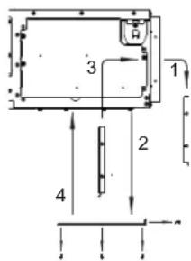
Preparations before installation
1 Relation of ceiling opening to unit and suspension bolt position. (See figure 5)
| Model A (mm) B (mm) |
| 15~32 550 588 |
| 40~50 700 738 |
| 63~80 1000 1038 |
| 100~125 1400 1438 |
1 Indoor unit
2 Pipe
3 Suspension bolt pitch (x4)
4 Suspension bolt pitch distance
For installation, choose one of the possibilities as listed further.
Standard rear suction (See figure 6a)
1 Ceiling surface
2 Ceiling opening
3 Service access panel (optional accessory)
4 Air filter
5 Air inlet duct
6 Duct service opening
7 Interchangeable plate
Installation with rear duct and duct service opening (See figure 6b)
Installation with rear duct, no duct service opening (See figure 6c)
NOTE

Before installation of the unit (in case of installation with duct, but no duct service opening): modify the position of the air filters.
1 Remove the air filter(s) at the outside of the unit
2 Remove the interchangeable plate
3 Install the air filter(s) from the inside of the unit
4 Reinstall the interchangeable plate
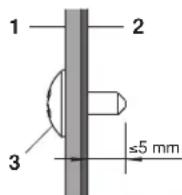
NOTE

When installing an air inlet duct, select fixing screws that shall stick out maximum 5 mm at the inside of the flange to protect the air filter from damage during maintenance of the filter.
1 Air inlet duct
2 Inside of the flange
3 Fixing screw
Mounting the air inlet panel with a canvas connection (See figure 7a)
Mounting the air inlet panel directly (See figure 7b)
1 Ceiling surface
2 Ceiling opening
3 Air inlet panel (Optional accessory)
4 Indoor unit (Back side)
5 Canvas connection for air inlet panel (Optional accessory)
Model A (mm)
| 15~32 610 |
| 40~50 760 |
| 63~80 1060 |
| 100~125 1460 |
Bottom suction (See figure 7c)
NOTE

The unit can be used with bottom suction by replacing the interchangeable plate by the air filter holding plate.
1 Air filter holding plate with air filter(s)
2 Interchangeable plate
NOTE

For other installation than standard installation, contact your Daikin dealer for details.
2 The fan speed for this indoor unit is preset to provide standard external static pressure.
3 Install the suspension bolts.
(Use M10 size bolt for the suspension bolt.) Use anchors for existing ceilings, and a sunken insert, sunken anchors or other field supplied parts for new ceilings to reinforce the ceiling in order to bear the weight of the unit.
Installation example
(See figure 3)
1 Anchor
2 Ceiling slab
3 Long nut or turn-buckle
4 Suspension bolt
5 Indoor unit
NOTE

■ All the above parts are field supplied.
■ For other installation than standard installation, contact your dealer for details.
Indoor unit installation
When installing optional accessories (except for the air inlet panel), read also the installation manual of the optional accessories. Depending on the field conditions, it may be easier to install optional accessories before the indoor unit is installed.
1 Install the indoor unit temporarily.
- Attach the hanger bracket to the suspension bolt. Be sure to fix it securely by using a nut and washer from the upper and lower sides of the hanger bracket. (See figure 4)
1 Nut (field supply)
2 Washer for hanger bracket (supplied with the unit)
3 Tighten (double nut)
2 Check if the unit is horizontally levelled.
- Do not install the unit tilted. The indoor unit is equipped with a built-in drain pump and float switch. (If the unit is tilted against condensate flow, the float switch may malfunction and cause water to drip.)
- Check if the unit is levelled at all four corners with a water level or a water-filled vinyl tube as shown in figure 9.
1 Water level
2 Vinyl tube
3 Tighten the upper nut.
Installing the duct
Connect the duct supplied in the field.
Air inlet side
- Attach the duct and intake-side flange (field supply).
- Connect the flange to the main unit with accessory screws (7).
- Wrap the intake-side flange and duct connection area with aluminum tape or something similar to prevent air escaping.

When attaching a duct to the intake side, be sure to attach an air filter inside the air passage on the intake side. (Use an air filter whose dust collecting efficiency is at least 50% in a gravimetric technique.)
The included filter is not used when the intake duct is attached.
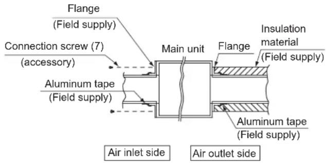
Air outlet side
- Connect the duct according to the air inside of the outlet-side flange.
- Wrap the outlet-side flange and the duct connection area with aluminum tape or something similar to prevent air escaping.

- Be sure to insulate the duct to prevent condensation from forming. (Material: glass wool or polyethylene foam, 25 mm thick)
- Use electric insulation between the duct and the wall when using metal ducts to pass metal laths of the net or fence shape or metal plating into wooden buildings.
- Be sure to explain about the way of maintaining and cleaning local procurements (air filter, grille (both air outlet and suction grille), etc.) to your customer.
Refrigerant piping work
For refrigerant piping of outdoor unit, refer to the installation manual supplied with the outdoor unit.
Before rigging tubes, check which type of refrigerant is used.

Installation shall be done by a licensed refrigeration technician, the choice of materials and installation shall comply with the applicable national and international codes. In Europe, EN378 is the applicable standard that shall be used.
■ Use a pipe cutter and flare suitable for the used refrigerant.
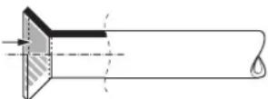
■ To prevent dust, moisture or other foreign matter from infiltrating the tube, either pinch the end, or cover it with tape.
■ Use copper alloy seamless pipes (ISO 1337).
■ The outdoor unit is charged with refrigerant.
To prevent water leakage, execute heat insulation work completely on both sides of the gas and liquid piping. When using a heat pump, the temperature of the gas piping can reach up to approximately 120°C, use insulation which is sufficiently heat resistant.
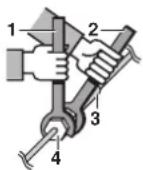
- Be sure to use both a spanner and torque wrench together when connecting or disconnecting pipes to/from the unit.
1 Torque wrench
2 Spanner
3 Piping union
4 Flare nut
■ Do not mix anything other than the specified refrigerant, such as air, etc..., inside the refrigerant circuit.
■ Use annealed material only for flare connections.
■ Refer to Table 1 for the dimensions of flare nut spaces and the appropriate tightening torque. (Overtightening may damage the flare and cause leaks.)
Table 1
| Pipe gauge (mm) | Tightening torque (N·m) | Flare dimension A (mm) | Flare shape |
| ∅6.4 15 | -17 8.7~9.1 | ||
| ∅9.5 33 | -39 12.8~13.2 | ||
| ∅12.7 50 | -60 16.2~16.6 | ||
| ∅15.9 63 | -75 19.3~19.7 |
When connecting the flare nut, coat the flare inner surface with ether oil or ester oil and initially tighten 3 or 4 turns by hand before tightening firmly.
If the refrigerant gas leaks during the work, ventilate the area. A toxic gas is emitted by the refrigerant gas being exposed to a fire.
■ Make sure there is no refrigerant gas leak. A toxic gas may be released by the refrigerant gas leaking indoor and being exposed to flames from an area heater, cooking stove, etc.
■ Finally, insulate as shown in the figures below.
Piping insulation procedure
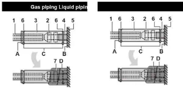
1 Piping insulation material (field supply)
2 Flare nut connection
3 Insulation for fitting (delivered with the unit)
4 Piping insulation material (main unit)
5 Main unit
6 Clamp (field supply)
7 Medium 1 sealing pad for gas piping (delivered with the unit) Medium 2 sealing pad for liquid piping (delivered with the unit)
A Turn seams up
B Attach to base
C Tighten the part other than the piping insulation material
D Wrap over from the base of the unit to the top of the flare nut connection

For local insulation, be sure to insulate local piping all the way into the pipe connections inside the unit.
Exposed piping may cause condensation or may cause burns when touched.
Cautions for brazing
■ Be sure to carry out a nitrogen blow when brazing.
Brazing without carrying out nitrogen replacement or releasing nitrogen into the piping will create large quantities of oxidized film on the inside of the pipes, adversely affecting valves and compressors in the refrigerating system and preventing normal operation.
When brazing while inserting nitrogen into the piping, nitrogen must be set to 0.02 MPa with a pressure-reducing valve (=just enough so that it can be felt on the skin).
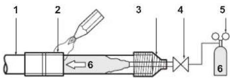
1 Refrigerant piping
2 Part to be brazed
3 Taping
4 Hands valve
5 Pressure-reducing valve
6 Nitrogen
Drain piping work
Installation of drain piping
Install the drain piping as shown in the figure and take measures against condensation. Improperly rigged piping could lead to leaks and eventually wet furniture and belongings.
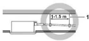
1 Hanging bar
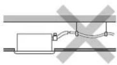
■ Install the drain pipes.
- Keep piping as short as possible and slope it downwards at a gradient of at least 1/100 so that air may not remain trapped inside the pipe.
- Keep pipe size equal to or greater than that of the connecting pipe (vinyl pipe of 25 mm nominal diameter and 32 mm outer diameter).
- Push the supplied drain hose as far as possible over the drain socket.
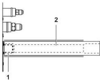
1 Drain socket (attached to the unit)
2 Drain hose (supplied with the unit)
- Tighten the metal clamp until the screw head is less than 4 mm from the metal clamp part as indicated in the illustration.
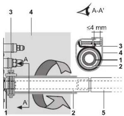
1 Drain socket (attached to the unit)
2 Drain hose (supplied with the unit)
3 Metal clamp (supplied with the unit)
4 Large sealing pad (supplied with the unit)
5 Drain piping (field supply)
- Wrap the supplied large sealing pad over the metal clamp and drain hose to insulate and fix it with clamps.
- Insulate the complete drain piping inside the building (field supply).
- If the drain hose cannot be sufficiently set on a slope, fit the hose with drain raising piping (field supply).
■ How to perform drain piping
(See figure 10)
1 Ceiling slab
2 Hanger bracket
3 Adjustable range
4 Drain raising pipe
5 Drain hose (supplied with the unit)
6 Clamp metal (supplied with the unit)
1 Connect the drain hose to the drain raising pipes, and insulate them.
2 Connect the drain hose to the drain outlet on the indoor unit, and tighten it with the clamp.
| Installation A (mm) | |
| Rear suction installation 231 | |
| When canvas duct is installed 350-530 | |
| When air inlet panel is directly installed | 231 |
■ Precautions
- Install the drain raising pipes at a height of less than 625 mm.
- Install the drain raising pipes at a right angle to the indoor unit and no more than 300 mm from the unit.
- To prevent air bubbles, install the drain hose level or slightly tilted up (≤75 mm).
- The drain pump mounted in this unit is the high lift type. The characteristic of this pump is that the higher the pump is the lower the drainage sound becomes. Therefore a drain pump height of 300mm is recommended.
NOTE

The incline of attached drain hose should be 75 mm or less so that the drain socket does not have to withstand additional force.
To ensure a downward slope of 1:100, install hanging bars every 1 to 1.5 m.
When unifying multiple drain pipes, install the pipes as shown in figure 11. Select converging drain pipes whose gauge is suitable for the operating capacity of the unit.
1 T-joint converging drain pipes
Testing of drain piping
After piping work is finished, check if drainage flows smoothly.
■ Add approximately 1 l of water gradually through the air discharge outlet. Check for water leaks. Method of adding water. See figure 8.
1 Water inlet
2 Portable pump
3 Water inlet cover
4 Bucket (adding water through water inlet)
5 Drain outlet for maintenance (with rubber drain plug)
6 Refrigerant pipes

Caution for drain socket
Do not remove the drain pipe plug. Water might leak out.
The drain outlet is only used to discharge water if the drain pump is not used or before maintenance. Gently put in and out the drain plug. Excessive force may deform the drain socket of the drain pan.
■ Pulling out the plug
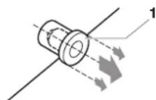
1 Drain plug
Do not wiggle the plug up and down
■ Pushing in the plug
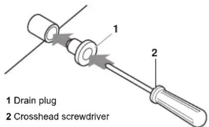
Set the plug and push it by using a crosshead screw-driver
First perform electric wiring work as instructed in "Electric wiring work" on page 6 and how to set the remote controller as explained in "Wiring example and how to set the remote controller" on page 7.
When electric wiring work is finished
Check drainage flow during COOL running, explained in "Test operation" on page 10.
When electric wiring work is not finished
Remove the switch box cover and connect the single-phase power supply and the remote controller to the terminals. (Refer to "Electric wiring work" on page 6 for switch box attachment/detachment.) (Refer to figure 12 and figure 14)
1 Switch box cover
2 Transmission wiring port
3 Power supply wiring port
4 Wiring diagram
5 Switch box
6 Plastic clamp
7 Remote controller wiring
8 Terminal board for unit transmission wiring
9 Power supply wiring
10 Indoor PC board 1
11 Power supply terminal board
12 Transmission wiring between units
13 Indoor PC board 2
14 Long sealing
15 Wiring
Next, press the inspection/test operation button ☐ on the remote controller. The unit will engage the test operation mode. Press the operation mode selector button ☐ until selecting fan operation
. Then, press the on/off button The indoor unit fan and drain pump will start up. Check that the water has drained from the unit. Press to go back to the first mode.
Electric wiring work
General instructions
All field wiring and components must be installed by a licensed electrician and must comply with relevant European and national regulations.
■ Use copper wire only.
■ Follow the "Wiring diagram" attached to the unit body to wire the outdoor unit, indoor units and the remote controller. For details on hooking up the remote controller, refer to the "Installation manual of the remote controller".
■ All wiring must be performed by an authorized electrician.
■ Attach the earth leakage circuit breaker and fuse to the power supply line.
A main switch or other means for disconnection, having a contact separation in all poles, must be incorporated in the fixed wiring in accordance with relevant local and national legislation. Note that the operation will restart automatically if the main power supply is turned off and then turned back on again.
■ Refer to the installation manual delivered with the outdoor unit for the size of power supply electric wire connected to the outdoor unit, the capacity of the earth leakage breaker and fuse and for wiring instructions.
■ Be sure to ground the air conditioner.
■ Do not connect the ground wire to:
- gas pipes: might cause explosions or fire if gas leaks.
- telephone ground wires or lightning rods: might cause abnormally high electric potential in the ground during lightning storms.
- plumbing pipes: no grounding effect if hard vinyl piping is used.
■ Make sure that earth wire between the pull relief and terminal is longer than other wires.
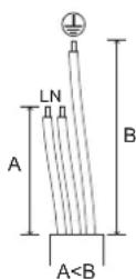
■ Be sure that the shape of the power supply cable and any other cable, before entering unit, should be as shown in this figure.
■ All cables entering the unit should be fixed by tie wraps (accessory).
■ Use long sealing (accessory) to block entrance of switch box as shown in figure 12.
Electrical characteristics
| Model | Hz | Volts | Voltage range | Power supply | |
| MCA | MFA | ||||
| 15 | 50/60 | 220-240/220 | ±10% | 0.4 | 16 A |
| 20 | 0.4 | ||||
| 25 | 0.4 | ||||
| 32 | 0.4 | ||||
| 40 | 0.8 | ||||
| 50 | 0.8 | ||||
| 63 | 0.9 | ||||
| 80 | 1.0 | ||||
| 100 | 1.5 | ||||
| 125 | 2.0 | ||||
MCA: Min. circuit Amps (A)
MFA: Max. Fuse Amps (A)
NOTE
For details, refer to "Electrical data" in the technical data book.

Specifications for field supplied fuses and wire
| Power supply wiring | |||
| Model Field fuses Wire Size | |||
| 15~125 16 A H0 | 5VV-U3G Local | codes | |
| Model Wire Size | |||
| 15~125 Sheathed wire (2) | 0.75-1.25 mm^2 | ||
NOTE
For details, refer to "Wiring example" on page 7.

Allowable length of transmission wiring between indoor and outdoor units, and between the indoor unit and the remote controller is as follows:
- Outdoor unit - indoor unit: max. 1000 m (total wiring length: 2000 m)
- Indoor unit - remote controller: max 500 m
Wiring example and how to set the remote controller
How to connect wiring
Remove the switch box cover as shown in figure 12, and make the connections.
1 Switch box cover
2 Switch box low voltage wiring inlet
3 Switch box high voltage wiring inlet
4 Wiring diagram
5 Switch box
Precautions
- Observe the notes mentioned below when wiring to the power supply terminal board.
- Use a round crimp-style terminal for insulation sleeve for connection to the terminal block for wiring the units. When none are available, follow the instructions below.

1 Round crimp-style terminal
2 Attach insulation sleeve
3 Wiring
- Do not connect wires of different gauge to the same power supply terminal. (Looseness in the connection may cause overheating.)
- When connecting wires of the same gauge, connect them according to the figure.


Use the specified electric wire. Connect the wire securely to the terminal. Lock the wire down without applying excessive force to the terminal. Use torques according to the table below.
Tightening torque (N·m)
| Terminal block for remote controller | 0.79~0.97 |
| Terminal block for power supply | 1.18~1.44 |
- When attaching the control box lid, make sure not to pinch any wires.
-
After all wiring connections are done, fill in any gaps in the casing wiring holes with putty or insulation material (field supply) thus to prevent small animals or dirt from entering the unit from outside and causing short circuits in the control box.
-
Do not connect wires of different gauge to the same grounding terminal. Looseness in the connection may deteriorate the protection.
- Remote controller cords and wires connecting the units should be located at least 50 mm away from power supply wiring. Not following this guideline may result in malfunction due to electrical noise.
- For the remote controller wiring, refer to the "Installation manual of the remote controller" supplied with the remote controller.
NOTE
The customer has the ability to select the remote controller thermistor.

- Never connect the power supply wiring to the terminal board for transmission wiring. This mistake could damage the entire system.
- Use only specified wires and tightly connect wires to the terminals. Be careful that wires do not place external stress on the terminals. Keep wiring in neat order so that they do not obstruct other equipment such as popping open the switch box cover. Make sure the cover closes tight. Incomplete connections could result in overheating, and in the worse case, electric shock or fire.
Keep total current of crossover wiring between indoor units less than 12 A. Branch the line outside the terminal block of the unit in accordance with the electrical equipment standards, when using two power wiring of a gauge greater than 2 mm^2 ( 1.6 ).
The branch must be sheathed in order to provide an equal or greater degree of insulation as power supply wiring itself.
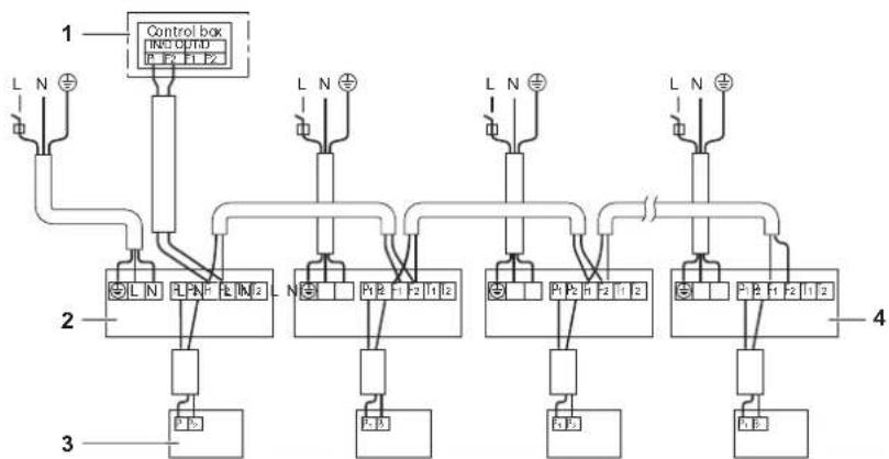
Wiring example
Fit the power supply wiring of each unit with a switch and fuse as shown in figure 16.
1 Power supply
2 Main switch
3 Power supply wiring
4 Transmission wiring
5 Switch
6 Fuse
7 BS unit REYQ only
8 Indoor unit
9 Remote controller
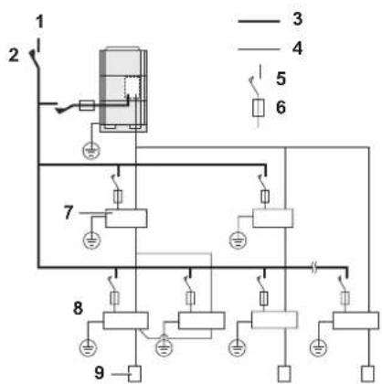
Complete system example (3 systems)
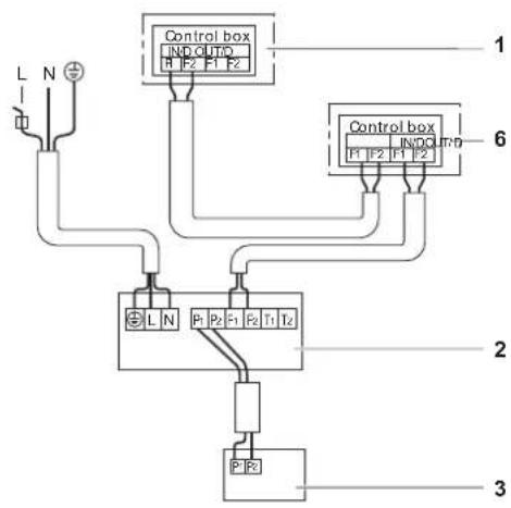
When using 1 remote controller for 1 indoor unit (Normal operation) (See figure 15)
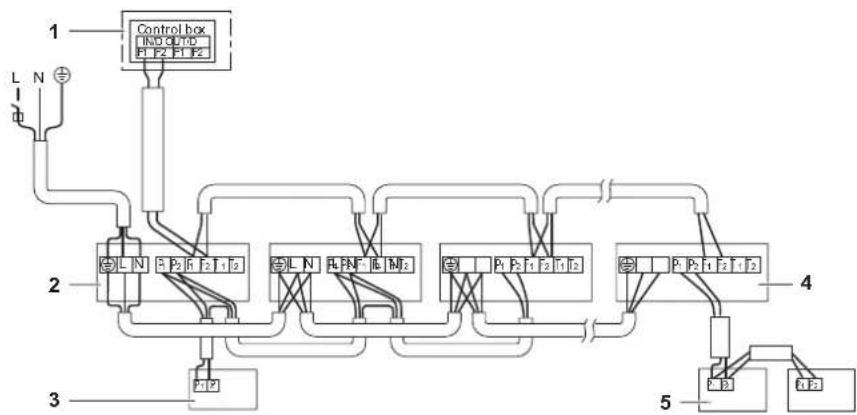
For group control or use with 2 remote controllers (See figure 17)
When including BS unit (See figure 13)
1 Outdoor unit
2 Indoor unit
3 Remote controller (optional accessories)
4 Most downstream indoor unit
5 For use with 2 remote controllers
6 BS unit
NOTE
It is not necessary to designate an indoor unit address when using group control. The address is automatically set when the power is activated.
Precautions
- A single switch can be used to supply power to units on the same system. However, branch switches and branch circuit breakers must be selected carefully.
- For a group control remote controller, choose the remote controller that suits the indoor unit which has the most functions.
- All transmission wiring except for the remote controller wiring is polarized and must match the terminal symbol.
- In case of group control, perform the remote controller wiring to the master unit when connecting to the simultaneous operation system (wiring to the slave unit is unnecessary).
- When controlling the simultaneous operation system with 2 remote controllers, connect it to the master unit (wiring to the slave unit is unnecessary).
- Be sure to connect the wiring to the master unit when combining with a simultaneous operating multi-type in group control.
- Do not ground the equipment on gas pipes, water pipes, lightning rods or crossground with telephones. Improper grounding could result in electric shock.
Field setting
Field setting must be made on the remote controller in function of the installation condition.
Setting can be made by changing the "Mode number", "First code No." and "Second code No.".
For setting and operation, refer to the "Field settings" in the installation manual of the remote controller.
Summary of field settings
| Mode No. (Note 1) | First code No. | Description of setting | Second code No. (Note 2) | |||||
| 01 02 03 04 | ||||||||
| 10 (20) | 0 | Filter contamination - Heavy/Light = Setting to define time between 2 filter cleaning display indications. (When contamination is high, setting can be changed to half the time inbetween 2 filter cleaning display indications.) | Ultra-long-life filter | Light | ±10,000 hrs. | ±5,000 hrs. | — | — |
| Long-life filter | ±2,500 hrs. ±100 hrs. | ±50 hrs. | ||||||
| Standard filter | ±200 hrs. ±100 hrs. | |||||||
| 2 | Thermostat sensor selection | Use both the unit sensor (or remote sensor if installed) AND the remote controller sensor. (See note 5+6) | Use unit sensor only (or remote sensor if installed). (See note 5+6) | Use remote controller sensor only. (See note 5+6) | — | |||
| 3 | Setting for display of time between 2 filter cleaning display indications | Display Do not display — — | ||||||
| 6 | Thermostat sensor in group control | Use unit sensor only (or remote sensor if installed). (See note 6) | Use both the unit sensor (or remote sensor if installed) AND the remote controller sensor. (See note 4+5+6) | — | — | |||
| 12 (22) | 0 | Output signal X1-X2 of the optional KRP1B PCB kit | Thermostat-on + compressor run | — Operation | Mal-function | |||
| 1 | ON/OFF input from outside (T1/T2 input) = Setting when forced ON/OFF is to be operated from outside. | Forced OFF | ON/OFF operation | — | — | |||
| 3 | Fan setting during thermostat OFF at heating operation | LL Set speed | OFF (See note 3) | — | ||||
| 4 | Differential automatic changeover | 0°C 1°C 2°C | 3°C (See note 7) | |||||
| 5 | Auto-restart after power failure | Disabled Enabled | —— | |||||
| 9 | Fixed cool/heat master | Disabled | Enabled | — | — | |||
| 15 (25) | 3 | Drain pump operation + humidifier interlock | Equipped | Not equipped | —— | |||
Note 1: Setting is carried out in the group mode, however, if the mode number inside parentheses is selected, indoor units can also be set individually.
Note 2: Factory settings of the Second code No. are marked in grey backgrounds.
Note 3: Only use in combination with optional remote sensor or when setting 10-2-03 is used.
Note 4: If group control is selected and remote control sensor is to be used, then set 10-6-02 & 10-2-03.
Note 5: If setting 10-6-02 + 10-2-01 or 10-2-02 or 10-2-03 are set at the same time, then setting 10-2-01, 10-2-02 or 10-2-03 have priority.
Note 6: If setting 10-6-01 + 10-2-01 or 10-2-02 or 10-2-03 are set at the same time, then setting for group connection, 10-6-01 has priority and for individual connection, 10-2-01, 10-2-02 or 10-2-03 have priority.
Note 7: More settings for Differential automatic change over temperatures are:
Second code No. 05 4°C
06 5°C
07 6°C
08 7°C
External static pressure settings
Settings for external static pressure can be achieved in 2 ways:
Using the airflow automatic adjustment function
Airflow automatic adjustment is the volume of blow-off air that has been automatically adjusted to the rated quantity.
1 Make sure the test run is done with a dry coil.
If the coil is not dry, run the unit for 2 hours with fan only to dry the coil.
2 Check if the power supply wiring to the air conditioning unit is completed along with the duct installation.
If a closing damper is installed in the air conditioning unit, make sure that it is open.
Also check if the air filter is properly attached into the air passage on the air suction side of the air conditioning unit.
3 If there is more than one air inlet and outlet, adjust the dampers so that the airflow rate of each air inlet and outlet is conform with the designed airflow rate.
Make sure the air conditioning unit is in fan operation mode. Press and set the airflow adjustment button on the remote controller to change the airflow rate to H or L.
4 Setting the airflow automatic adjustment settings.
When the air conditioning unit is running in fan operation mode perform the next steps:
- stop the air conditioning unit,
- go to field setting mode,
- select mode No. 21 (or 11 in case of group setting),
- set the first code No. to "7",
- set the second code No. to "03".
Return to normal operating mode after setting these settings and press the ON/OFF operation button. The operation lamp will light up and the air conditioning unit will start the fan operation for airflow automatic adjustment.

Do not adjust the dampers during fan operation for airflow automatic adjustment.
After 1 to 8 minutes, the air conditioning unit stops operating automatically when the fan operation for airflow automatic adjustment has been carried out, the operation lamp will be off.
| Mode No. | First code No. | Second code No. | Setting content |
| 11 (21) 7 | 01 Airflow adjustment is OFF | ||
| 02 Completion of airflow adjustment | |||
| 03 Start of airflow adjustment | |||
5 When the air conditioning unit has stopped, check on an indoor unit if the second code No. of mode No. 21 is set to "02".
If the air conditioning unit does not stop operating or the second code No. is not "02", repeat step 4.
If the outdoor unit is not turned on, the display on the remote controller will show "U4" or "UH" (refer to "Test operation" on page 10). However, you can continue setting this function because these messages are only applicable to outdoor units.
After setting this function, be sure to turn on the outdoor unit before performing the test operation on the outdoor unit.
If any other error display occurs on the display of the remote controller, refer to "Test operation" on page 10 and the operation manual of the outdoor unit. Check the defective point.

If the external static pressure higher than 100 Pa, do not use airflow automatic adjustment function.
If there is no change after airflow adjustment in the ventilation paths, be sure to perform setting the airflow automatic adjustment again.
Contact your dealer if there is no change after performing airflow adjustment in the ventilation paths, after performing the test operation of the outdoor unit or when the air conditioning unit is moved to another location.
If booster fans, an outdoor air processing unit or HRV via duct are used, do not use airflow automatic adjustment control with a remote controller.
If the ventilation paths have been changed, perform the setting of the airflow automatic adjustment again as described above from step 3 onwards.
Using the remote controller
Check on an indoor unit if the second code of mode No. 21 is set to "01" (= factory setting). Change the second code according to the external static pressure of the duct to be connected as shown in table 2.
NOTE
The second code No. is set to "01" by default.

Table 2
| ModeNo. | 1stcodeNo. | 2ndcodeNo. | External static pressure (Pa) | |||||||||
| FXSQ | ||||||||||||
| 15 | 20 | 25 | 32 | 40 | 50 | 63 | 80 | 100 | 125 | |||
| 13(23) | 6 | 01 | 30 | 30 | 30 | 30 | 30 | 30 | 40 | 40 | 50 | |
| 0 | 2 | - | - | - | - | |||||||
| 03 | 30 | 30 | 30 | 30 | 30 | 30 | - | |||||
| 04 | 40 | 40 | 40 | 40 | 40 | 40 | 40 | 40 | ||||
| 05 | 50 | 50 | 50 | 50 | 50 | 50 | 50 | 50 | ||||
| 06 | 60 | 60 | 60 | 60 | 60 | 60 | 60 | 60 | ||||
| 07 | 70 | 70 | 70 | 70 | 70 | 70 | 70 | 70 | ||||
| 08 | 80 | 80 | 80 | 80 | 80 | 80 | 80 | 80 | ||||
| 09 | 90 | 90 | 90 | 90 | 90 | 90 | 90 | 90 | ||||
| 10 | 100 | 100 | 100 | 100 | 100 | |||||||
| 11 | 110 | 110 | 110 | 110 | 110 | |||||||
| 12 | 120 | 120 | 120 | 120 | 120 | |||||||
| 13 | 130 | 130 | 130 | 130 | 130 | |||||||
| 14 | 140 | 140 | 140 | 140 | 140 | |||||||
| 15 | 150 | 150 | 150 | 150 | 150 | |||||||
Control by 2 Remote Controllers (Controlling 1 indoor unit by 2 remote controllers)
When using 2 remote controllers, one must be set to "MAIN" and the other to "SUB".
MAIN/SUB CHANGEOVER
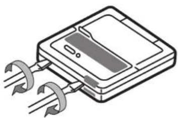
■ Insert a wedge-head screwdriver into the recess between the upper and lower part of the remote controller and, working from the 2 positions, pry off the upper part. (See figure 18)
(The remote controller PC board is attached to the upper part of the remote controller.)
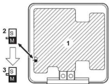
■ Turn the main/sub changeover switch on one of the two remote controller PC boards to "S". (See figure 19)
(Leave the switch of the other remote controller set to "M".)
1 Remote controller PC board
2 Factory setting
3 Only one remote controller needs to be changed
Computerised control (forced off and on/off operation)
1 Wire specifications and how to perform wiring
- Connect input from outside to terminals T1 and T2 of the terminal board (remote controller to transmission wiring).
| Wire specification Sheathed vinyl cord or cable (2 wire) | |
| Gauge | 0.75-1.25 mm ^2 |
| Length Max. 100 m | |
| External terminal Contact that can ensure the minimum applicable load of 15 V DC, 10 mA | |
2 Actuation
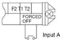
- The following table explains "forced off" and "on/off operations" in response to input A.
| Forced off on/off operation | |
| Input "on" stops operation | input off → on: turns on the unit (impossible by remote controllers) |
| Input "off" enables control | input on → off: turns off the unit by remote controller |
3 How to select forced off and on/off operation
- Turn the power on and then use the remote controller to select operation.
- Set the remote controller to the field set mode. For details, refer to the chapter "How to set in the field", in the remote controller manual.
- When in the field set mode, select mode No. 12, then set the first code No. to "1". Then set second code (position) No. to "01" for forced off and to "02" for on/off operation. (forced off at factory set.) (See figure 20)
1 Second code No.
2 Mode No.
3 First code No.
4 Field set mode
Centralized control
For centralized control, it is necessary to designate the group No. For details, refer to the manual of each optional controller for centralized control.
Installation of the decoration panel
Refer to the installation manual attached to the decoration panel.
After installing the decoration panel, ensure that there is no space between the unit body and decoration panel.
Test operation
Refer to the installation manual of the outdoor unit.
The operation lamp of the remote controller will flash when an error occurs. Check the error code on the liquid crystal display to identify the trouble.
| Error code Meaning | |
| R8Error in power supply to indoor unit | |
| C1 | Transmission error between fan driver PCB and controller PCB of the indoor unit |
| C6 | Improper combination of fan driver PCB of the indoor unit or setting failure in control PCB type |
| U3Test operation of the indoor unit has not been finished | |
If any of the items in following table are displayed on the remote controller, there may be a problem with the wiring or power, so check the wiring again.
| Error code Meaning | |
| There is a short circuit at the forced off terminals (T1, T2) | |
| U4 or UH | - The power on the outdoor unit is off- The outdoor unit has not been wired for power supply- Incorrect transmission of forced off wiring |
| no display | - The power on the indoor unit is off- The indoor unit has not been wired for power supply- Incorrect transmission wiring, forced off wiring or remote controller wiring |
Maintenance

Caution
■ Only a qualified service person is allowed to perform maintenance.
■ Before obtaining access to terminal devices, all power supply circuits must be interrupted.
■ Do not use water or air of 50^ C or higher for cleaning air filters and outside panels.
When cleaning the heat exchanger, be sure to remove the switchbox, fan motor, auxiliary electric heater and drain pump. Water or detergent may deteriorate the insulation of electronic components and result in burn-out of these components.
If the main power supply is turned off during operation, operation will restart automatically after the power turns back on again.
How to clean the air filter
Clean the air filter when the display shows " " (TIME TO CLEAN AIR FILTER).
Increase the frequency of cleaning if the unit is installed in a room where the air is extremely contaminated.
If the dirt becomes impossible to clean, change the air filter. (Air filter for exchange is optional.)
1 Open the suction grille. (Only for bottom suction.)
Slide both knobs simultaneously as shown and then pull them downward.
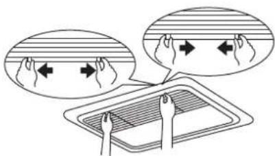
If chains are present, unhook the chains.
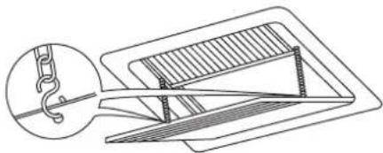
natural_image
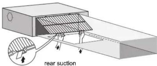
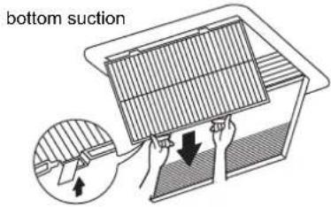
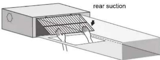
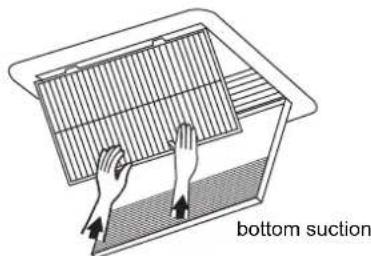
Technical line drawing of a mechanical assembly with a hook and structural components (no text or symbols)2 Remove the air filters.
Remove the air filters by pulling their cloth upward (rear suction) or backward (bottom suction).
3 Clean the air filter.
Use vacuum cleaner (A) or wash the air filter with water (B).
(A) Using a vacuum cleaner
(B) Washing with water
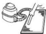
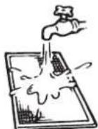
When the air filter is very dirty, use soft brush and neutral detergent.
Remove water and dry in the shade.
4 Fix the air filter.
Align the two hanger brackets and push the two clips in their place (pull the cloth if necessary).
Confirm that four hangers are fixed.
5 Shut the air inlet grille. (Only for bottom suction.)
Refer to item no. 1.
6 After turning on the power, press FILTER SIGN RESET button.
The "TIME TO CLEAN AIR FILTER" display is turned off.
How to clean air outlet and outside panels
■ Clean with soft cloth.
■ When it is difficult to remove stains, use water of neutral detergent.
■ Clean the air inlet grille when it is shut.
NOTE

Do not use gasoline, benzene, thinner, polishing powder, liquid insecticide. It may cause discolouring or warping.
Do not let the indoor unit get wet. It may cause an electric shock or a fire.
Start up after a long stop
Confirm the following:
- Check that the air inlet and outlet are not blocked. Remove any obstacle.
■ Check if the earth is connected.
Clean the air filter and outside panels.
■ After cleaning the air filter, make sure to attach it.
Turn on the main power supply switch.
■ The control panel display lights when the power is turned on.
■ To protect the unit, turn on the main power switch at least 6 hours before operation.
What to do when stopping the system for a long period
Turn on FAN OPERATION for half a day and dry the unit.
■ Refer to the operation manual of the outdoor unit.
Cut off the power supply.
■ When the main power switch is turned on, some wattage is being consumed even if the system is not operating.
■ The remote controller display is turned off when the main power switch is turned off.
Disposal requirements
Dismantling of the unit, treatment of the refrigerant, of oil and of other parts must be done in accordance with relevant local and national legislation.
Wiring diagram
: FIELD WIRING BLK : BLACK PNK : PINK
[NO TEXT]
: CONNECTOR BLU : BLUE RED : RED
□□□
: SCREW TERMINAL BRN : BROWN WHT : WHITE
GRN : GREEN YLW : YELLOW
ORG : ORANGE
A1P.....PRINTED CIRCUIT BOARD
A2P.....PRINTED CIRCUIT BOARD (FAN)
C1.....CAPACITOR
C105.....CAPACITOR
HAP ......INDICATION LAMPS
K1R.....MAGNETIC RELAY
L1R......REACTOR
M1F ......MOTOR (INDOOR FAN)
M1P .....MOTOR (DRAIN PUMP)
PS....SWITCHING POWER SUPPLY
R1......RESISTOR (CURRENT SENSOR)
R2......RESISTOR (CURRENT SENSOR)
R1T.....THERMISTOR (SUCTION)
R2T......THERMISTOR (LIQUID)
R3T.....THERMISTOR (COIL)
S1L ......FLOAT SWITCH
V1R.....DIODE BRIDGE
V2R.....POWER MODULE
X1M ....TERMINAL STRIP (POWER SUPPLY)
X2M TERMINAL BLOCK (CONTROL)
Y1E.....ELECTRONIC EXPANSION VALVE COIL
Z1C......FERRITE CORE
Z2C.....FERRITE CORE
Z1F ......NOISE FILTER
CONNECTOR (OPTIONAL ACCESSORY)
X28A......CONNECTOR (POWER SUPPLY FOR WIRING)
X33A......CONNECTOR (FOR WIRING)
X35A......CONNECTOR (POWER SUPPLY FOR WIRING)
X38A......CONNECTOR (FOR WIRING)
WIRED REMOTE CONTROLLER : Wired remote controller
(OPTIONAL ACCESSORY) : (Optional accessory)
SWITCH BOX (INDOOR) : Switch box (indoor)
TRANSMISSION WIRING : Transmission wiring
CENTRAL REMOTE CONTROLLER : Central remote controller
INPUT FROM OUTSIDE : Input from outside
COMMON POWER SUPPLY : Common power supply
NOTE

- USE COPPER CONDUCTORS ONLY.
- WHEN USING THE CENTRAL REMOTE CONTROLLER, SEE MANUAL FOR CONNECTION TO THE UNIT.
- WHEN CONNECTING THE INPUT WIRES FROM OUTSIDE, FORCED "OFF" OR "ON/OFF" CONTROL OPERATION CAN BE SELECTED BY THE REMOTE CONTROLLER. SEE INSTALLATION MANUAL FOR MORE DETAILS.
- REFER TO INSTALLATION MANUAL.
Inhalt Seite
natural_image
Technical line drawing of a mechanical assembly with a hook and structural components (no text or symbols)M1F ......MOTOR (INNENLÜFTER)
M1P .....MOTOR (KONDENSATPUMPE)
PS......STROMVERSORGUNG FÜR SCHALTKREIS
R3T......THERMISTOR (SPULE)
S1L ....SCHWIMMERSCHALTER
V1R......DIODENBRÜCKE
V2R....STROMVERSORGUNGSMODUL
X1M ......ANSCHLUSSLEISTE (STROMVERSORGUNG)
(OPTIONAL ACCESSORY)
Avant installation....1
(Voir figure 1 et figure 2)
natural_image
Technical line drawing of a mechanical assembly with a magnified inset showing a hook and structural components (no text or symbols)natural_image
Illustration of hands placing a grid on a surface with 'aspiration' text label (no other symbols or numbers)R3T...... THERMISTANCE (BOBINE)
natural_image
Technical line drawing of a mechanical assembly with a hook and structural components (no text or symbols)A1P ...... PRINTPLAAT
A2P ...... PRINTPLAAT (VENTILATOR)
C1...... CONDENSATOR
C105...... CONDENSATOR
DS1 KEUZESCHAKELAAR
F1U .....ZEKERING (T, 3,15 A, 250 V)
F2U ZEKERING (T, 5 A, 250 V)
F3U .....ZEKERING (T, 6,3 A, 250 V)
HAP...... INDICATIELAMPJES
K1R MAGNETISCH RELAIS
L1R...... REACTOR
M1F ...... MOTOR (BINNENVENTILATOR)
M1P...... MOTOR (AFVOERPOMP)
PS ...... SCHAKELENDE VOEDING
Q1DI...... AARDLEKSCHAKELAAR
R1...... WEERSTAND (STROOMSENSOR)
R2...... WEERSTAND (STROOMSENSOR)
R1T .... THERMISTOR (AANZUIGING)
R2T..... THERMISTOR (VLOEISTOF)
R3T...... THERMISTOR (SPOEL)
S1L...... VLOTTERSCHAKELAAR
V1R ......DIODEBRUG
V2R ......ELEKTRISCHE VOEDINGSMODULE
X1M.....AANSLUITKLEMMENSTROOK (VOEDING)
X2M.....AANSLUITKLEMMENBLOK (BEDIENING)
Y1E...... ELEKTRONISCHE EXPANSIEKLEP SPIRAAL
Z1C...... FERRIETKERN
Z2C...... FERRIETKERN
Z1F...... RUISFILTER
CONNECTOR (OPTIONEEL ACCESSOIRE)
X28A...... CONNECTOR (VOEDING VOOR BEDRADING)
X33A...... CONNECTOR (VOOR BEDRADING)
X35A...... CONNECTOR (VOEDING VOOR BEDRADING)
X38A.... CONNECTOR (VOOR BEDRADING)
10 Tablero PC interior 1
13 Tablero PC interior 2
natural_image
Technical line drawing of a mechanical assembly with a hook and structural components (no text or symbols)R3T......TERMISTOR (SERPENTÍN)
S1L ......INTERRUPTOR DE FLOTADOR
V1R.....PUENTE DE DIODOS
(OPTIONAL ACCESSORY)
natural_image
Technical line drawing of a mechanical assembly with a hook and structural components (no text or symbols)natural_image
Illustration of hands placing a mesh into a container labeled 'aspirazio' (no other text or symbols)natural_image
Technical line drawing of a mechanical assembly with a hook and structural components (no text or symbols)R3T.....AIZOHTHPAS (MONADAS FAN COIL)
1 Porca (fornecimento local)
natural_image
Technical line drawing of a mechanical assembly with a hook and structural components (no text or symbols)R1......RESISTOR (SENSOR DE CORRENTE)
R2......RESISTOR (SENSOR DE CORRENTE)
natural_image
Technical line drawing of a mechanical assembly with a hook and structural components (no text or symbols)| : MECTHAY PPOVODKA | |
| : PA3bEM | |
| : KLEMMA C BINTOBbIM KPEPLEHcIeM | |
MCA: Min. devre Amp (A)
MFA: Maks. Sigorta Amp (A)
NOT

natural_image
Technical line drawing of a mechanical assembly with a hook and structural components (no text or symbols)natural_image
Blank grid paper with no text, numbers, or symbols

natural_image
Blank grid paper with no text, numbers, or symbols

natural_image
Blank grid paper with no text, numbers, or symbols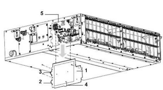
12
14
flowchart
graph TD
    A["Control box IND OUT"] --> B["Inductors P1, P2, P3"]
    C["Control box IN DOUT"] --> D["Inductors P1, P2, P3"]
    E["Terminal Block P F2"] --> F["Ground"]
    style A fill:#f9f,stroke:#333
    style C fill:#f9f,stroke:#333
    style E fill:#f9f,stroke:#333
13
flowchart
graph TD
    A["Control box"] --> B["L N ⊕"]
    A --> C["L N ⊕"]
    A --> D["L N ⊕"]
    A --> E["L N ⊕"]
    A --> F["L N ⊕"]
    A --> G["L N ⊕"]
    A --> H["L N ⊕"]
    A --> I["L N ⊕"]
    A --> J["L N ⊕"]
    A --> K["L N ⊕"]
    A --> L["L N ⊕"]
    A --> M["L N ⊕"]
    A --> N["L N ⊕"]
    A --> O["L N ⊕"]
    A --> P["L N ⊕"]
    A --> Q["L N ⊕"]
    A --> R["L N ⊕"]
    A --> S["L N ⊕"]
    A --> T["L N ⊕"]
    A --> U["L N ⊕"]
    A --> V["L N ⊕"]
    A --> W["L N ⊕"]
    A --> X["L N ⊕"]
    A --> Y["L N ⊕"]
    A --> Z["L N ⊕"]
    A --> AA["L N ⊕"]
    A --> AB["L N ⊕"]
    A --> AC["L N ⊕"]
    A --> AD["L N ⊕"]
    A --> AE["L N ⊕"]
    A --> AF["L N ⊕"]
    A --> AG["L N ⊕"]
    A --> AH["L N ⊕"]
    A --> AI["L N ⊕"]
    A --> AJ["L N ⊕"]
    A --> AK["L N ⊕"]
    A --> AL["L N ⊕"]
    A --> AM["L N ⊕"]
    A --> AN["L N ⊕"]
    A --> AO["L N ⊕"]
    A --> AP["L N ⊕"]
    A --> AQ["L N ⊕"]
    A --> AR["L N ⊕"]
    A --> AS["L N ⊕"]
    A --> AT["L N ⊕"]
    A --> AU["L N ⊕"]
    A --> AV["L N ⊕"]
    A --> AW["L N ⊕"]
    A --> AX["L N ⊕"]
    A --> AY["L N ⊕"]
    A --> AZ["L N ⊕"]
    A --> BA["L N ⊕"]
    A --> BB["L N ⊕"]
    A --> BC["L N ⊕"]
    A --> BD["L N ⊕"]
    A --> BE["L N ⊕"]
    A --> BF["L N ⊕"]
    A --> BG["L N ⊕"]
    A --> BH["L N ⊕"]
    A --> BI["L N ⊕"]
    A --> BJ["L N ⊕"]
    A --> BK["L N ⊕"]
    A --> BL["L N ⊕"]
    A --> BM["L N ⊕"]
    A --> BN["L N ⊕"]
    A --> BO["L N ⊕"]
    A --> BP["L N ⊕"]
    A --> BQ["L N ⊕"]
    A --> BR["L N ⊕"]
    A --> BS["L N ⊕"]
    A --> BT["L N ⊕"]
    A --> BU["L N ⊕"]
    A --> BV["L N ⊕"]
    A --> BW["L N ⊕"]
    A --> BX["L N ⊕"]
    A --> BY["L N ⊕"]
    A --> BZ["L N ⊕"]
    A --> CA["L N ⊕"]
    A --> CBL["L N ⊕"]
    A --> CCL["L N ⊕"]
    A --> CDL["L N ⊕"]
    A --> CEL["L N ⊕"]
    A --> CFL["L N ⊕"]
    A --> CGL["L N ⊕"]
    A --> CHL["L N ⊕"]
    A --> CIL["L N ⊕"]
    A --> CJL["L N ⊕"]
    A --> CKL["L N ⊕"]
    A --> CLN["L N ⊕"]
    A --> CDN["L N ⊕"]
    A --> CEN["L N ⊕"]
    A --> CFN["L N ⊕"]
    A --> CGN["L N ⊕"]
    A --> CHN["L N ⊕"]
    A --> CINL["L N ⊕"]
15
16
flowchart
graph TD
    A["Control box"] --> B["Node 1"]
    B --> C["Node 2"]
    C --> D["Node 3"]
    D --> E["Node 4"]
    E --> F["Node 5"]
    F --> G["Node 6"]
    G --> H["Node 7"]
    H --> I["Node 8"]
    I --> J["Node 9"]
    J --> K["Node 10"]
    K --> L["Node 11"]
    L --> M["Node 12"]
    M --> N["Node 13"]
    N --> O["Node 14"]
    O --> P["Node 15"]
    P --> Q["Node 16"]
    Q --> R["Node 17"]
    R --> S["Node 18"]
    S --> T["Node 19"]
    T --> U["Node 20"]
    U --> V["Node 21"]
    V --> W["Node 22"]
    W --> X["Node 23"]
    X --> Y["Node 24"]
    Y --> Z["Node 25"]
17
natural_image
Illustration of a rectangular electronic device with three curved leads and a central screen (no text or symbols)18
19

20

- INSTALLATION AND OPERATION MANUAL
- Daikin Industries Czech Republic s.r.o.
- Contents Page
- Before installation
- Precautions
- Accessories
- Optional accessories
- For the following items, take special care during construction and check after installation is finished
- Notes to the installer
- Important information regarding the refrigerant used
- Selecting installation site
- Preparations before installation
- Standard rear suction (See figure 6a)
- NOTE
- Mounting the air inlet panel directly (See figure 7b)
- Bottom suction (See figure 7c)
- Indoor unit installation
- Installing the duct
- Air inlet side
- Air outlet side
- Refrigerant piping work
- Cautions for brazing
- Drain piping work
- Installation of drain piping
- ■ Install the drain pipes.
- ■ How to perform drain piping
- ■ Precautions
- Testing of drain piping
- Caution for drain socket
- When electric wiring work is finished
- When electric wiring work is not finished
- Electric wiring work
- General instructions
- Specifications for field supplied fuses and wire
- Wiring example and how to set the remote controller
- How to connect wiring
- Wiring example
- Complete system example (3 systems)
- Field setting
- External static pressure settings
- Using the airflow automatic adjustment function
- Using the remote controller
- Control by 2 Remote Controllers (Controlling 1 indoor unit by 2 remote controllers)
- MAIN/SUB CHANGEOVER
- Computerised control (forced off and on/off operation)
- Wire specifications and how to perform wiring
- Actuation
- How to select forced off and on/off operation
- Centralized control
- Installation of the decoration panel
- Test operation
- Maintenance
- Caution
- How to clean the air filter
- Remove the air filters.
- Clean the air filter.
- Fix the air filter.
- How to clean air outlet and outside panels
- Start up after a long stop
- Confirm the following:
- What to do when stopping the system for a long period
- Disposal requirements
- Wiring diagram
- CONNECTOR (OPTIONAL ACCESSORY)
- Inhalt Seite
- CONNECTOR (OPTIONEEL ACCESSOIRE)
Brand : DAIKIN
Model : FXSQ63A2VEB
Category : Air-conditioner